 Hiroki Akehashi
 Izuru Takewaki
- Department of Architecture and Architectural Engineering, Graduate School of Engineering, Kyoto University, Kyoto, Japan
A new method for simultaneous optimal design of main building structures and viscous dampers is proposed for elastic-plastic multi-degree-of-freedom (MDOF) building structures subjected to the critical double impulse which is regarded as a representative of the main part of near-fault ground motions. The critical double impulse is characterized by the maximum energy input to the total system by the second impulse and the sum of the restoring force and the damping force in the first story attains zero by this critical input. The objective function is the maximum interstory drift along the building height. The original optimization problem is transformed into a problem of removing the most inactive story stiffness and damper damping coefficient. An efficient sensitivity-based design algorithm is developed for this simultaneous optimal design problem of main building structures and viscous dampers. It is pointed out that the order of changes of structural stiffness and damper damping magnitude is critical to the achievement of reasonable designs and cycle-by-cycle alternating redesign of story stiffness and damper damping coefficient is effective for its achievement. The double impulse pushover (DIP) analysis proposed in the previous paper (Akehashi and Takewaki, 2019) for determining the input velocity level of the critical double impulse is also conducted to disclose the response characteristics of the designed building structures and dampers. It is shown that the proposed design method enables the high yield-strength design with effective seismic energy absorption and the high limit-strength design effective for extremely large disturbances. The distributions of the maximum acceleration responses in an initial design and the final design are also presented for the one-cycle sine wave corresponding to the critical double impulse.
Introduction
In the ordinary building structural design using passive dampers, the main frames are designed based on usual structural design requirements and the passive dampers are installed to upgrade the structural performance against severe natural disturbances, e.g., severe earthquake ground shaking, severe strong wind. For this reason, the simultaneous optimization of the main frames and the passive dampers has never been tackled except some theoretical interests (Khansefid et al., 2019) and a general design guideline (ASCE, 2017). However, both interdependent characteristics are getting much interest recently. Actually, it is expected that the simultaneous optimization enables the design with higher structural performances and broader structural design perspectives. The high yield-strength design with effective seismic energy absorption and the high limit-strength design effective for extremely large disturbances are examples taking full advantage of such both interdependent characteristics.
As for simultaneous optimization, Austin and Pister (1985) introduced a mathematical programming approach in the optimal design of elastic-plastic moment-resisting frames including friction dampers. Takewaki (1999) proposed an approach to the simultaneous optimization of main frames and passive dampers using optimality criteria conditions. Cimellaro (2007) extended the approach due to Takewaki (1999). However, these papers are treating only elastic structures. Cimellaro and Retamales (2007) investigated a problem of damper installation and retrofitting of building structures with the concept of softening. As a technique of softening, the weakening of beam-column joints is considered. Cimellaro et al. (2009) developed an integrated design approach of inelastic controlled structural systems by using the active control strategy. Lavan and Dargush (2009) investigated the multi-objective evolutionary seismic design with passive energy dissipation systems by using the genetic algorithm. Castaldo and De Iuliis (2014) presented an integrated method of the optimal seismic design of structural and viscoelastic bracing-damper systems for an equivalent single-degree-of-freedom system and a proportionally dampers multi-degree-of-freedom system. Khansefid and Bakhshi (2019) developed an advanced algorithm for two-step integrated optimization of actively controlled non-linear structure under mainshock–aftershock sequences. Idels and Lavan (2020) tackled a problem of simultaneous optimal design of non-linear building frames and non-linear viscous dampers.
After 1990's, many researches on the optimal design of passive dampers have been conducted. These researches are summarized in the review papers and monographs (e.g., Takewaki, 2009; Domenico et al., 2019). Zhang and Soong (1992) proposed a sequential search algorithm (SSA) to find the best position of dampers sequentially. Takewaki (1997) introduced a concept of optimality criteria-based damper placement. Garcia (2001) and Garcia and Soong (2002) developed a simplified sequential search algorithm (SSSA). Singh and Moreschi (2001, 2002) investigated optimal design problems by introducing the optimality conditions and the non-linear programming technique. Uetani et al. (2003) presented a practical damper optimization method for building frames based on the mathematical programing which can be applied to general building structures with plastic responses. Lavan and Levy (2006) proposed a methodology for the optimal viscous damper design for realistic ground motion records under the maximum drift constraints. Silvestri and Trombetti (2007) investigated novel approaches for the optimal insertion of seismic viscous dampers in shear-type structures and compared the optimization performances of several previously proposed algorithms. Aydin et al. (2007) tackled the optimal damper distribution problem for seismic rehabilitation of planar building structures. Whittle et al. (2012) compared some methods for the optimal viscous damper placement. Lavan and Avishur (2013) proposed a design method of dampers for elastic-plastic frames. Adachi et al. (2013) proposed a practical theory of optimal relief-force distribution for oil dampers by setting the maximum interstory drift and the maximum building-top acceleration as the objective performances. Murakami et al. (2013) treated a problem of simultaneous optimal damper placement using oil, hysteretic and inertial mass dampers and proposed a sensitivity-based algorithm. Shiomi et al. (2018) investigated a problem of optimal hysteretic damper placement for elastic-plastic multi-degree-of-freedom (MDOF) shear building models under the double impulse as a representative of near-fault ground motions and proposed a sensitivity-based method. Palermo et al. (2018) investigated a practical and simple design procedure of passive dampers for the preliminary seismic design which is followed by a non-linear time history analysis. Akehashi and Takewaki (2019) tackled a problem of optimal design of passive dampers for a designed elastic-plastic shear building model under a pulse-type ground motion modeled by a critical double impulse introduced by Kojima and Takewaki (2015). They introduced the concept of “Double Impulse Pushover (DIP)” analysis to clarify the limit-state responses of elastic-plastic shear building models with optimally-placed dampers. Akehashi and Takewaki (2020) extended the concept of Takewaki (1997) into higher-order modes and investigated the effect of higher modes on the elastic-plastic responses and the damper placement. Cetin et al. (2019) showed a method using the critical excitation proposed by Takewaki (2013). Singh and Moreschi (2002) and Dargush and Sant (2005) introduced a design method using GA.
In this paper, a new method for simultaneous optimal design of main structures and viscous dampers is proposed for elastic-plastic MDOF structures subjected to the critical double impulse which is regarded as a representative of the main part of near-fault ground motions. An efficient sensitivity-based design algorithm is developed for the above-mentioned simultaneous optimal design problem of main structures and viscous dampers. It is pointed out that the order of changes of structural stiffness and damper damping magnitude is critical to the achievement of reasonable designs. The DIP analysis proposed in the previous paper (Akehashi and Takewaki, 2019) for determining the input velocity level of the critical double impulse is also conducted to disclose the response characteristics of the designed building structures and dampers. It is shown that, while the model designed for a small input velocity level can reduce the maximum interstory drifts in the elastic response range, it exhibits a large deformation concentration in the middle and lower stories for the critical double impulse with larger input velocity level. On the other hand, while the model designed for a large input velocity level exhibits larger elastic interstory drifts in the upper stories for the critical double impulse with smaller input velocity level, it shows a favorable interstory drift distribution for the critical double impulse with larger input velocity level. The proposed design method enables the high yield-strength design with effective seismic energy absorption and the high limit-strength design effective for extremely large disturbances.
Simultaneous Optimization of Elastic-Plastic Building Structures and Viscous Dampers
Critical Double Impulse
Near-fault ground motions are getting much interest recently because it was made clear that these ground motions possess peculiar pulse-type characteristics and are influential for various types of building structures (Bertero et al., 1978). It is known that this pulse-type waves affect high-rise buildings and base-isolated buildings with long natural periods. To simulate such peculiar pulse-type characteristics, Kojima and Takewaki (2015) proposed the double impulse with reverse directions. The acceleration g(t) of the double impulse can be expressed by
where V is the velocity amplitude, δ(t) is the Dirac delta function and t0 is the time interval of two impulses. Some investigations using the double impulse have been made for single-degree-of-freedom (SDOF) models (Kojima and Takewaki, 2015; Akehashi et al., 2018a,b), investigations on MDOF models are extremely limited (Saotome et al., 2018; Shiomi et al., 2018; Akehashi and Takewaki, 2019, 2020). This may result from the fact that the simple energy balance law for the simple evaluation of the maximum response cannot be expected in MDOF models because of the phase lag.
The most important subject on the double impulse is the determination of the critical timing of two impulses. This issue was solved by Akehashi and Takewaki (2019). The essence is shown here briefly. Consider an N-story MDOF shear building model of mass mi and story stiffness ki in the i-th story. Let ui denote the horizontal displacement of mass in the i-th story and let ci, fi denote the damping coefficient of the damper in the i-th story and the restoring force in the i-th story. Since the displacements do not change instantaneously at the action of the second impulse, the strain energy does not change at the timing of action of the second impulse. In this case, the input energy by the second impulse can be expressed by
Equation (2) clearly indicates that, when reaches the maximum, the input energy by the second impulse becomes the maximum. The necessary condition of the maximization of is . The dynamic equilibrium of the whole building leads to the fact that the sum of the inertial forces is equal to the story shear force in the first story . This means that the extremum condition becomes . This simple critical condition can be used in the time-history response analysis.
Importance of Simultaneous Design of Building Structures and Dampers
In this paper, a problem of simultaneous optimization of main structures and added viscous dampers is dealt with. Figure 1 shows the concept of simultaneous design of main structures and dampers. The structural designer can conduct a structural design with higher structural performance by designing supplemental dampers for a predetermined main structure without design option. The structural performance indicates the damage or the limit state of a frame. Therefore, the displacement or ductility factor is assumed here as is often used in the displacement-based design. Furthermore, the simultaneous design of main structures and dampers can provide a high yield-strength design by using small earthquake ground motions as the design earthquake ground motions or a high limit-strength design by using severe earthquake ground motions as the design earthquake ground motions. This concept will be explained in numerical examples. Takewaki (1999) and Cimellaro (2007) proposed another methods of simultaneous optimization of main structures and added viscous dampers. Since their methods are aimed for elastic design, they correspond to the high yield-strength design. On the other hand, the present method enables not only the high yield-strength design but also the high limit-strength design. The possibility of such designs will be discussed in numerical examples using the DIP analysis. Recently recorded near-fault pulse-type earthquake ground motions of large amplitude require the development of such high limit-strength design.
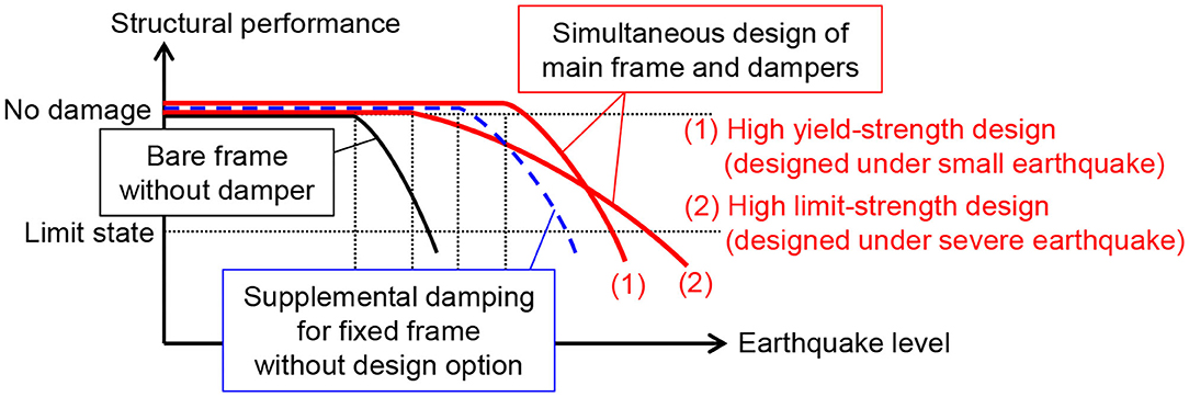
Figure 1. Concept of simultaneous design of main structures and dampers.
Problem of Simultaneous Optimization and Solution Algorithm
The problem of simultaneous optimization of main structures and added viscous dampers may be stated as follows: To minimize the maximum interstory drift under the condition on the specified total quantity of story stiffnesses of main structures and the specified total quantity of damping coefficients of viscous dampers. It seems reasonable to deal with this problem by using the sensitivity-based approach that includes the time-history response analysis for the critical double impulse and the finite difference method. The problems treated here will be explained next.
Consider the following problem.
[Problem]
In this problem, dmax,i, ki, ci, WkF, WcF are the maximum interstory drift in the i-th story, the story stiffness of the i-th story, the damping coefficient of the viscous damper in the i-th story, the final value of the sum of story stiffnesses, the final value of the sum of the damping coefficients of dampers, respectively.
The direct procedure to solve the above mentioned-problem is not simple because a mathematical programming approach may be necessary. To overcome this difficulty, a practical and simple procedure without time-consuming mathematical programming techniques is proposed based on the method due to Adachi et al. (2013). The aim of this procedure is to find the most inactive stiffness of the frame and the most inactive damper damping coefficient and to reduce the quantity of such frame stiffness and damper damping coefficient sequentially.
The solution algorithm for this transformed problem may be described as follows.
[Algorithm]
Step 1 Assume an initial design which satisfies and .
Step 2 Decrease the story stiffness by a small stiffness Δk only in the i-th story. Repeat this procedure N times for all the stories and make N models. Input the critical double impulse to the modified N MDOF models and compute the maximum interstory drifts by the non-linear time-history response analysis. Find the model which has the smallest increment of the maximum interstory drift (finding of the smallest response sensitivity design). Regard this model as a new design. Repeat this procedure nk times. The number nk indicates the number of repetition cycles in Step 2.
Step 3 Decrease the damper damping coefficient by a small damping coefficient Δc only in the i-th story. Repeat this procedure N times for all the stories and make N models. Input the critical double impulse to the modified N MDOF models and compute the maximum interstory drifts by the non-linear time-history response analysis. Find the model which has the smallest increment of the maximum interstory drift (finding of the smallest response sensitivity design). Regard this model as a new design. Repeat this procedure nc times. The number nc indicates the number of repetition cycles in Step 3.
Step 4 Repeat Step 2 and Step 3 nkc times. The number nkc indicates the number of global repetition cycles including Step 2 and Step 3.
The flow of this algorithm is shown in Figure 2 and the schematic diagrams of the variations of the sum of the story stiffnesses and the sum of the damping coefficients of dampers are presented in Figure 3. Wk0 = WkF + nkcnkΔk, Wc0 = WcF + nkcncΔc in Figure 3 indicate the initial values of the sum of the story stiffnesses and the sum of the damping coefficients of dampers. In this paper, the story stiffness distribution and the damping coefficient distribution of dampers of the initial design are assumed to be uniform along height. It is important to remark that, because the proposed algorithm seeks for a design of story stiffnesses and damper damping coefficients with the smallest value of the maximum interstory drift at each level of the sum of story stiffnesses and the sum of damper damping coefficients, the final design satisfying the constraints is certainly the optimal design of the above-mentioned optimal design problem. Since the algorithm is simple, it is possible to add some constraints, i.e., the setting of the minimum story stiffness, the constraint that the lower story stiffness is larger than the upper story stiffness (the story stiffnesses are monotonically decreasing toward the top).
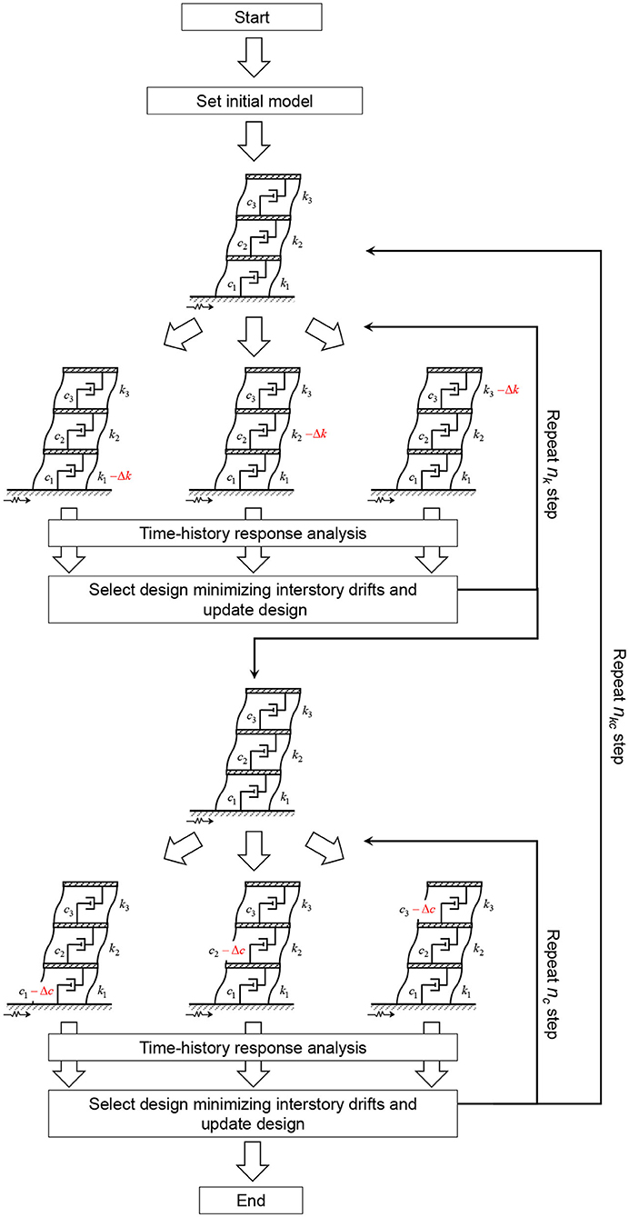
Figure 2. Schematic diagram of proposed solution algorithm.
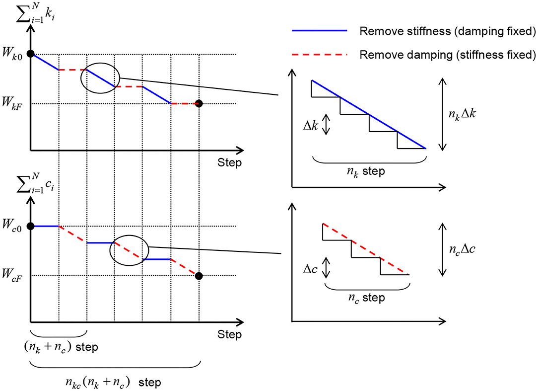
Figure 3. Change of sum of story stiffnesses and sum of added damping coefficients throughout process of proposed solution algorithm.
Wk0 and Wc0 were introduced to specify an initial design of the frame and dampers. Designers can set these values based on their experiences. On the other hand, WkF and WcF were introduced to obtain a desirable design of the frame and dampers exhibiting acceptable inelastic responses of the frame. Especially, the value WkF is given in view of the fundamental natural period of the final design and the value WcF is given in view of the damping ratio of the final design or the cost for dampers. The frame and dampers with WkF and WcF are not necessarily the unique or target design. If the designers prefer the design even in the intermediate process to WkF andWcF, they can adopt such design.
Numerical Example
Consider a 12-story shear building model of bilinear hysteresis (kinematic hardening) in the story shear-story drift relation with viscous dampers. It is assumed that the structural damping does not exist. All the floor masses have the same value . The common story height is 4[m]. The common yield interstory drift is dy=4/150[m] and the post-yield stiffness ratio is α= 0.2. The target value of the sum of story stiffnesses is set to . This value was given so that the final design has the fundamental natural period of about 1.2[s]. Since the structural model is a shear building model, the reduction in one story stiffness does not affect the story stiffness in other stories.
The double impulse as a representative of near-fault pulse-type ground motions is treated as the input ground motion (Kojima and Takewaki, 2015). The critical timing of the second impulse can be determined depending on the input velocity level V and the structural model so as to attain the maximum energy input by the second impulse to the structure. Akehashi and Takewaki (2019) showed that this critical timing can be obtained without repetition of time-history response analysis. They clarified that this critical timing corresponds to the time of zero value of the story shear force in the first story. This double impulse is called the critical double impulse and only this critical double impulse is treated in this paper. The employment of the critical double impulse enables the smart pursuit of non-linear resonant responses.
Non-linear time-history response analysis has been conducted for the critical double impulse. The software used for the non-linear time-history response analysis is the original one whose accuracy was checked by the comparison with other usual software.
Influence of Algorithm Parameters
In this section, the influence of setting of the parameters nk, nc, nkc on the final design is investigated. Figures 4, 5 show the design process corresponding to the parameters . As stated above, . The value of the WcF is given so that the final design has the fundamental-mode damping ratio of about 0.1. The input level of the critical double impulse is V = 0.25[m/s] and the elastic design is achieved.
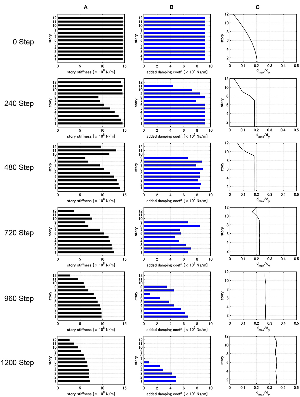
Figure 4. Change of distribution of story stiffness, distribution of added damping coefficient and distribution of dmax,i/dy throughout process of optimization (nk = nc = 1, nkc = 600). (A) Distribution of story stiffness. (B) Distribution of damper damping coefficient. (C) Distribution of dmax,i/dy.
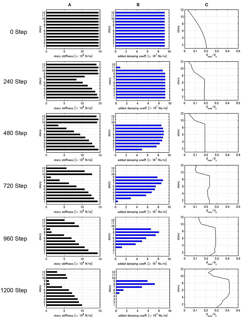
Figure 5. Change of distribution of story stiffness, distribution of added damping coefficient and distribution of dmax,i/dy throughout process of optimization (nk = nc = 60, nkc = 10). (A) Distribution of story stiffness. (B) Distribution of damper damping coefficient. (C) Distribution of dmax,i/dy.
In Figure 4, nk = nc = 1, nkc = 600 are used. On the other hand, in Figure 5, nk = nc = 60, nkc = 10 are employed. In both cases, the total steps are the same nkc(nk + nc) = 1,200. In the initial design, uniform distributions of story stiffness and damper damping coefficient are used. The fundamental natural period of the initial design is 0.828 s and the damping ratio of the dampers is 0.238.
In the case of nk = nc = 1, nkc = 600 (Figure 4), the maximum interstory drifts of the initial model are small in the middle and upper stories. Until about 400 steps, the maximum interstory drift is decreased. In this process, the story stiffnesses in the middle stories and the damping coefficients in the upper stories are reduced. In other words, the interstory drifts in the upper stories are increased and those in the lower stories are improved. After 400 steps, the story stiffnesses and the damping coefficients in the upper stories are reduced and the uniform maximum interstory drifts are attained at about 800 steps. After about 800 steps, the story stiffnesses and the damping coefficients are reduced so as to keep the uniformity of the maximum interstory drifts. It seems that the quick reflection of the optimal change (redesign) of the story stiffness of a frame or the damping coefficient of dampers on the next optimal redesign of the damping coefficient of dampers or the story stiffness of the frame is absolutely necessary for a desirable distribution (monotonically increasing toward the bottom) of story stiffnesses of the frame. This procedure strongly supports the concept of simultaneous optimal design.
On the other hand, in the case of nk = nc = 60, nkc = 10 (Figure 5), the story stiffnesses in the middle stories and the damping coefficients in the upper stories are reduced in the beginning process as in the previous case (Figure 4). After about 400 steps, due to the small number of nkc and the large amount of dampers, the reduction of story stiffness in the upper stories and the reduction of dampers in the middle stories are delayed (to make the dampers in the middle stories effective by making the story stiffnesses in the upper stories larger). As a result, an unrealistic design with small story stiffnesses in the 8 and 9-th stories is obtained.
Further investigations lead to the conclusion that, in the case of a relatively small number of nkc (relatively large number of nk, nc), the setting of the initial assignment of Wk0 and Wc0 yields an unfavorable result of the distribution of story stiffness and damping coefficient in the final design as shown in Figure 5. This phenomenon is remarkable in the case of a large value of Wc0. It is also noted that unrealistic designs are obtained in other cases of a relatively small number of nkc (for example, a design without damping only in the middle stories, a design with a drastic change of the story stiffness in a specific story, and so on). Finally, it can be concluded that the setting of a larger number of nkc causes a small effect of Wk0, Wc0 on the final design and leads to a favorable design. It is desirable to set the number of nkc as large as possible after determining the number of the total steps of the algorithm. Then, the numbers of nk, nc are automatically determined.
Influence of Input Level
In this section, the influence of the input velocity level of the double impulse on the final design is investigated. Three input velocity levels V = 0.25, 1.0, 1.5[m/s] are selected. The velocity level V = 0.25[m/s] corresponds to the elastic design.
Figures 6–8 show the design for Wc0 = 65 × 107 [Ns/m], WcF = 20 × 107 [Ns/m], that for and that for , WcF = 5 × 10⁷[Ns/m]. The other parameters are common, nk = nc = 1, nkc = 600. In all cases, the value Wc0 − WcF is chosen as the same value, i.e., the reduction value Δc of the damping coefficient is the same.
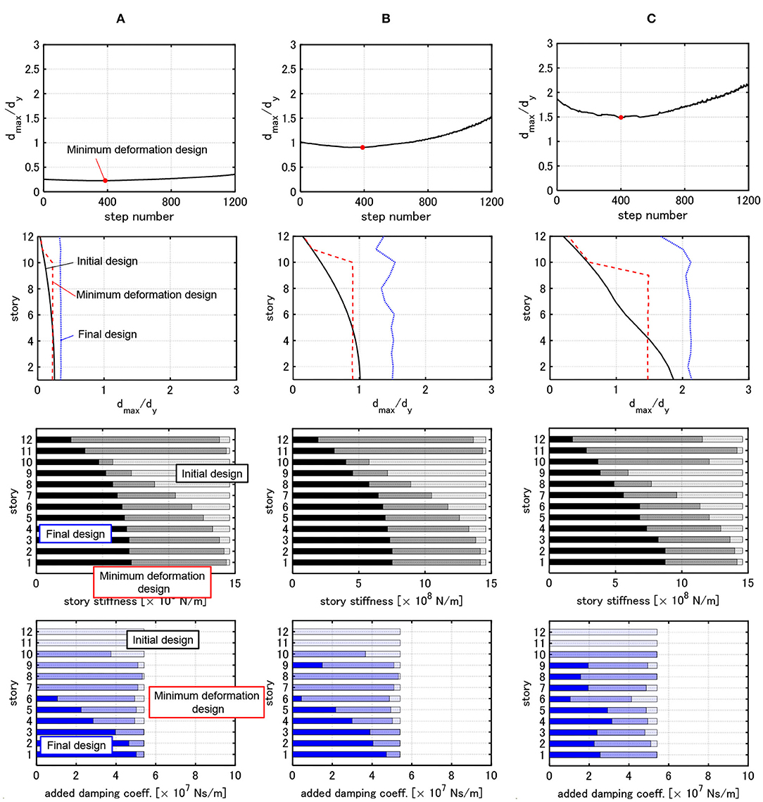
Figure 6. Change of maximum deformation, distribution of dmax,i/dy, distribution of story stiffness and distribution of damper damping coefficient of 3 cases with . (A) Model designed under critical double impulse with V = 0.25[m/s]. (B) Model designed under critical double impulse with V = 1.0[m/s]. (C) Model designed under critical double impulse with V = 1.5[m/s].
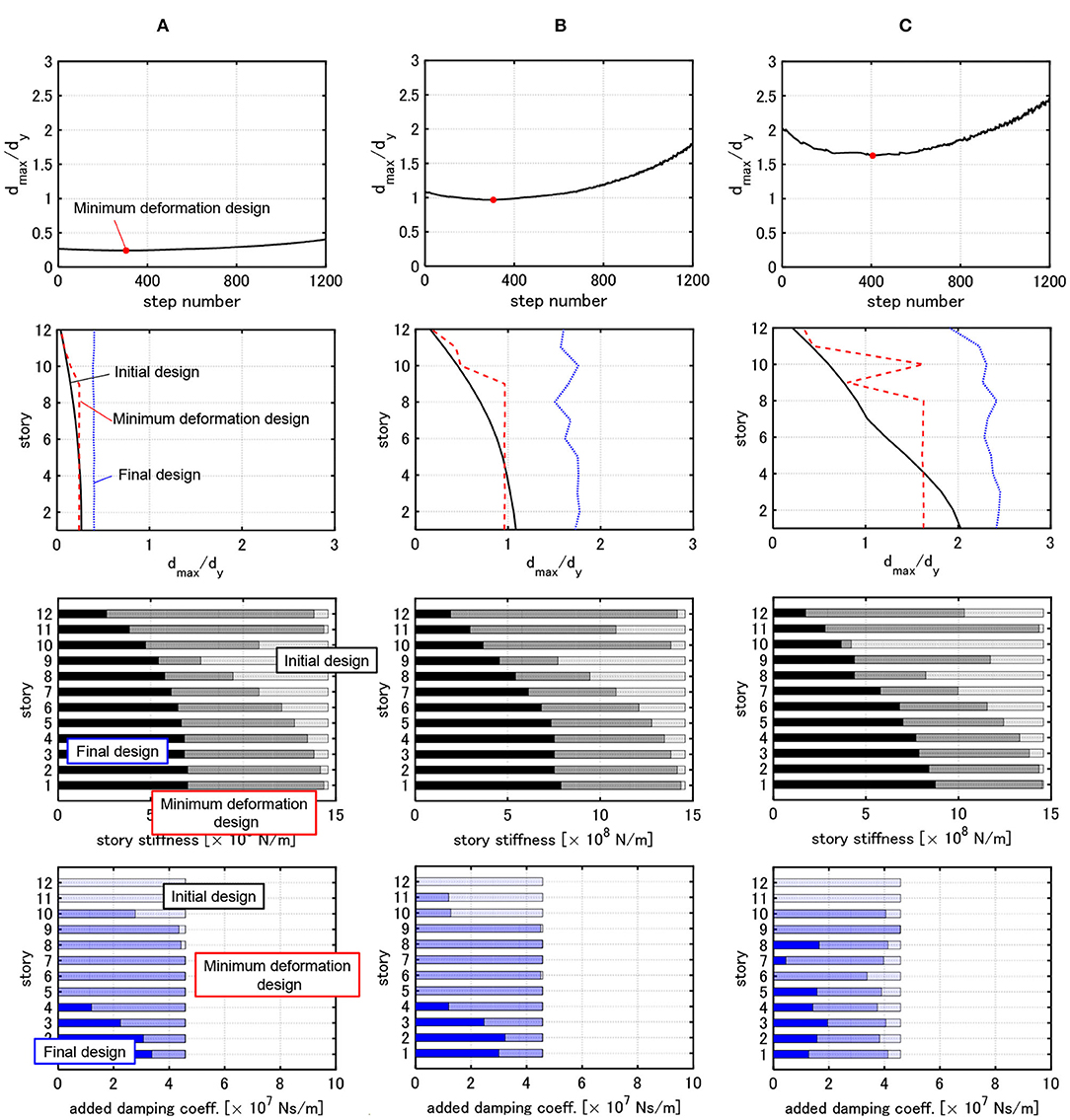
Figure 7. Change of maximum deformation, distribution of dmax,i/dy, distribution of story stiffness and distribution of damper damping coefficient of 3 cases with . (A) Model designed under critical double impulse with V = 0.25[m/s]. (B) Model designed under critical double impulse with V = 1.0[m/s]. (C) Model designed under critical double impulse with V = 1.5[m/s].
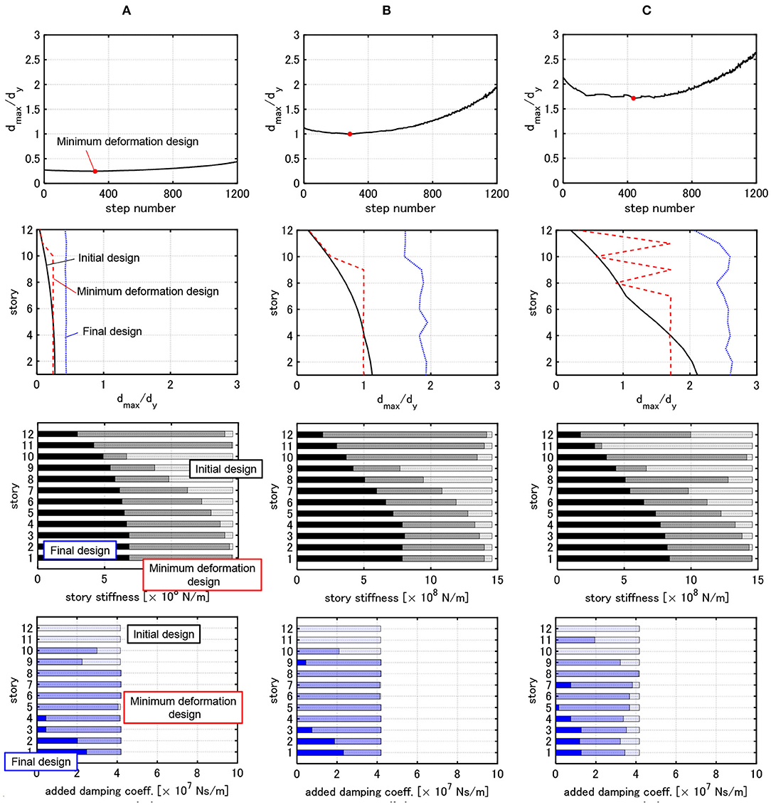
Figure 8. Change of maximum deformation, distribution of dmax,i/dy, distribution of story stiffness and distribution of damper damping coefficient of 3 cases with . (A) Model designed under critical double impulse with V = 0.25[m/s]. (B) Model designed under critical double impulse with V = 1.0[m/s]. (C) Model designed under critical double impulse with V = 1.5[m/s].
It can be observed from Figures 6–8 that, as the velocity level V used for the design becomes larger, the story stiffnesses in the lower stories become relatively large and those in the upper stories become relatively small. This indicates that the distribution of story stiffness exhibits remarkable non-uniformity. In this case, the interstory drifts in the upper stories increase much compared to the initial design and the those in the lower stories increase a little bit. As a result, the interstory drifts of all the stories are close to a uniform distribution against the large input. Furthermore, as the input velocity level used for the design becomes larger, the dampers concentrated to the lower stories spread into the middle and lower stories.
The minimum deformation design in Figures 6–8 indicates the design in which is minimized. In the design before attaining this minimum deformation design, is decreased. On the other hand, in the design after attaining this minimum deformation design, is increased. In the minimum deformation design for all cases, the uniform distribution of the maximum interstory drifts is attained in the middle and lower stories. In this case, although the reduction of damping coefficients is developed in the upper stories, the maximum interstory drifts in the upper stories are smaller than those in the middle and lower stories. This is because the reduction of story stiffnesses is not developed sufficiently. In addition, before and after attaining the minimum deformation design, the maximum interstory drifts exhibit an almost uniform distribution. This indicates that, even if the maximum interstory drifts in the upper stories are made larger, the maximum interstory drifts in the lower stories are not improved.
In the elastic design, the interstory drift and the story shear (especially base shear) are important design indices. However, since the restoring-force characteristic is specified in the inelastic design, constraining story ductility factors seems to be sufficient for the drift and strength checks.
DIP Analysis
In this section, the DIP analysis is conducted. The DIP analysis was proposed by Akehashi and Takewaki (2019) by extending the procedure of the incremental dynamic analysis (IDA) (Vamvatsikos and Cornell, 2001) to the non-linear resonant case. The DIP analysis provides the relation between the maximum interstory drift and the input velocity level of the critical double impulse.
It should be reminded that only the critical double impulse is treated here, i.e., the interval of two impulses of the double impulse changes depending on the input velocity level (also depending on the maximum interstory drift).
Figures 9–11 show the maximum interstory drift distributions by the DIP analysis for 9 models obtained in Figures 6–8. The velocity level is increased from V = 0.5 [m/s] to = 2.0 [m/s] by 0.25 [m/s]. In other words, the frame and dampers are designed for the velocity V = 0.25, 1.0, 1.5 [m/s] by using the proposed design procedure (Figures 6–8). Then, each designed frame with designed dampers is subjected to several critical double impulses (from V = 0.5 [m/s] to V = 2.0 [m/s] by 0.25 [m/s]) with seven velocity levels by using the DIP analysis concept.
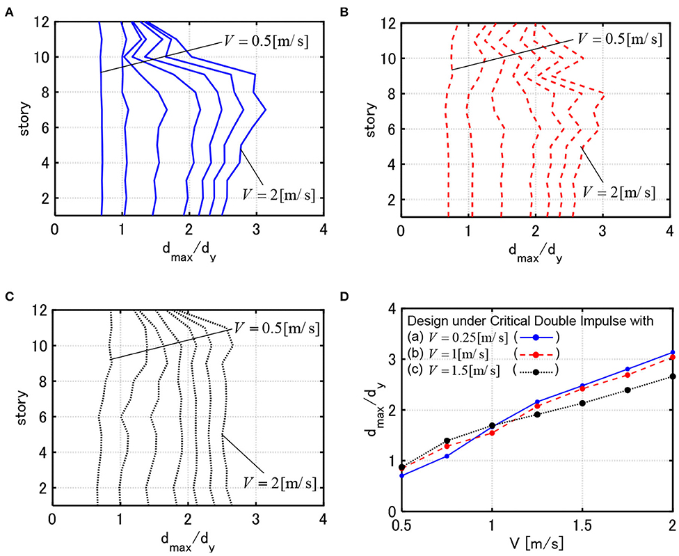
Figure 9. DIP analysis for 3 models with . (A) Response of model designed under critical double impulse with V = 0.25[m/s]. (B) Response of model designed under critical double impulse with V = 1.0[m/s]. (C) Response of model designed under critical double impulse with V = 1.5[m/s]. (D) Comparison of maximum deformations for 3 models.
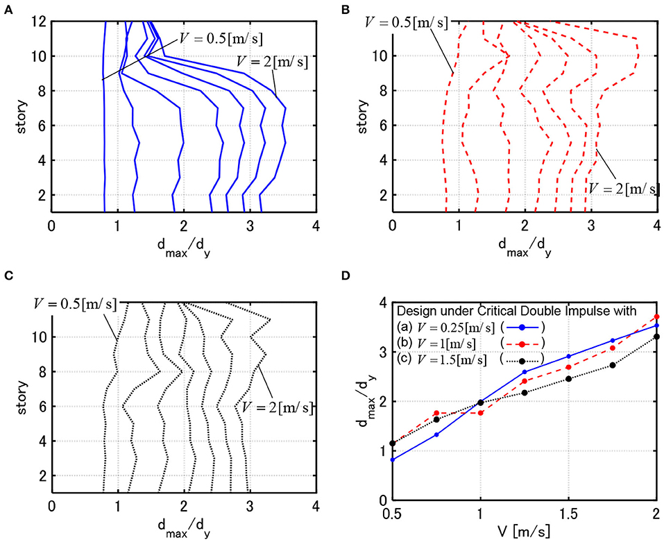
Figure 10. DIP analysis for 3 models with . (A) Response of model designed under critical double impulse with V = 0.25[m/s]. (B) Response of model designed under critical double impulse with V = 1.0[m/s]. (C) Response of model designed under critical double impulse with V = 1.5[m/s]. (D) Comparison of maximum deformations for 3 models.
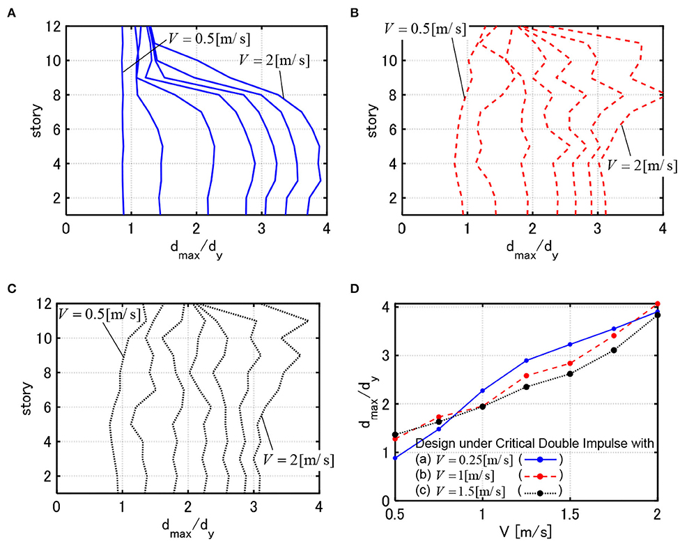
Figure 11. DIP analysis for 3 models with W = 5 × 10⁷[Ns/m]. (A) Response of model designed under critical double impulse with V = 0.25[m/s]. (B) Response of model designed under critical double impulse with V = 1.0[m/s]. (C) Response of model designed under critical double impulse with V = 1.5[m/s]. (D) Comparison of maximum deformations for 3 models.
It can be observed that, while the model designed for V = 0.25[m/s] can reduce the maximum interstory drifts in the elastic response range, it exhibits a large deformation concentration in the middle and lower stories for the critical double impulse with larger input velocity level. This indicates the characteristic of the high yield-strength design. On the other hand, while the model designed for V = 1.5[m/s] exhibits larger elastic interstory drifts in the upper stories for the critical double impulse with smaller input velocity level, it shows a favorable interstory drift distribution for the critical double impulse with larger input velocity level by distributing the interstory drifts into the upper stories. This phenomenon does not depend on the value of WcF. This indicates the characteristic of the high limit-strength design.
Acceleration Response Under One-Cycle Sine Wave
In this section, the maximum acceleration response of the model designed by using the critical double impulse is investigated by employing the corresponding one-cycle sine wave. This use of the corresponding one-cycle sine wave results from the fact that, while the double impulse is useful for evaluating the deformation, it is not appropriate for evaluating the acceleration response. This characteristic may result from the property that the double impulse induces high-frequency responses which are not amplified in the response to the one-cycle sine wave resonant to the fundamental frequency of the model. In the transformation from the critical double impulse into the one-cycle sine wave, the acceleration amplitude Ap of the one-cycle sine wave can be expressed by Ap = (1.222/2)ωpV in terms of the resonant circular frequency ωp(= π/t0) (Akehashi et al., 2018a; Hashizume and Takewaki, 2020).
Figures 12–14 show the maximum acceleration responses of 9 models, obtained in Figures 6–8, for the one-cycle sine waves equivalent to the critical double impulses with V = 0.5, 1.0[m/s]. The responses of all models for the one-cycle sine wave equivalent to V = 0.5[m/s] are almost elastic. In these figures, the acceleration responses of the initial design models for the one-cycle sine waves equivalent to the critical double impulses with V = 0.5, 1.0[m/s] are also included. In all models, the maximum accelerations of the final designs are reduced compared to the initial design. This is because the story stiffnesses are decreased and the fundamental natural period is prolonged.
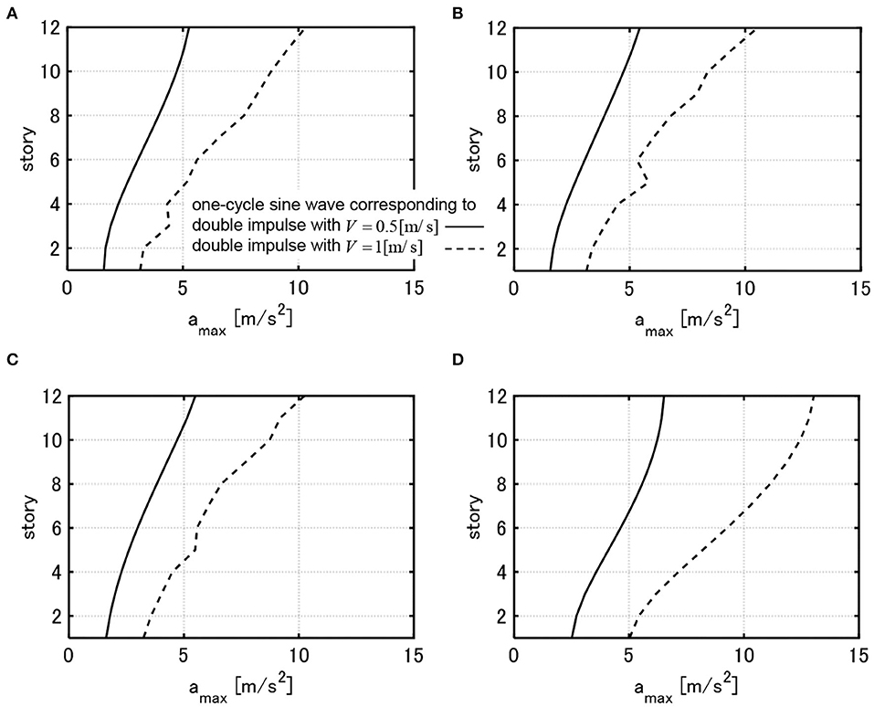
Figure 12. Maximum floor acceleration of 3 models with and these initial design model under one-cycle sine wave corresponding to critical double impulse with V = 0.5, 1.0[m/s]. (A) Model designed under critical double impulse with V = 0.25[m/s]. (B) Model designed under critical double impulse with V = 1.0[m/s]. (C) Model designed under critical double impulse with V = 1.5[m/s]. (D) Initial design.
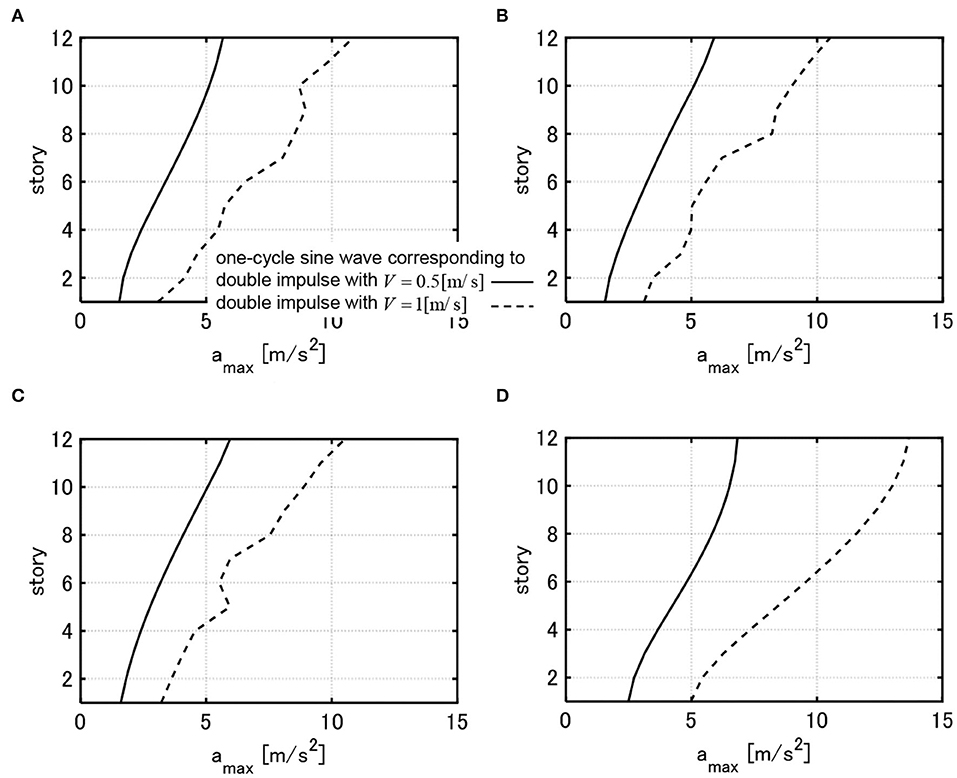
Figure 13. Maximum floor acceleration of 3 models with and these initial design model under one-cycle sine wave corresponding to critical double impulse with V = 0.5, 1.0[m/s]. (A) Model designed under critical double impulse with V = 0.25[m/s]. (B) Model designed under critical double impulse with V = 1.0[m/s]. (C) Model designed under critical double impulse with V = 1.5[m/s]. (D) Initial design.
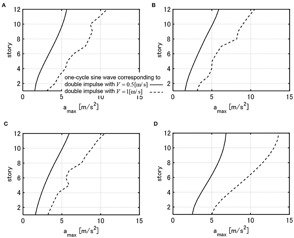
Figure 14. Maximum floor acceleration of 3 models with and these initial design model under one-cycle sine wave corresponding to critical double impulse with V = 0.5, 1.0[m/s]. (A) Model designed under critical double impulse with V = 0.25[m/s]. (B) Model designed under critical double impulse with V = 1.0[m/s]. (C) Model designed under critical double impulse with V = 1.5[m/s]. (D) Initial design.
When WcF is the same, the maximum accelerations do not change so much irrespective of the design value of V. The shape of acceleration responses in the elastic range differ a little bit depending on the design value of V and this results from the difference in the distribution of story stiffnesses. In addition, the irregular distribution of acceleration responses for the one-cycle sine wave equivalent to V = 1.0[m/s] is due to the plastic deformation which induces the higher-mode response components.
Investigation of Drift Response for Amplified Recorded Near-Faults Ground Motions
In this section, the maximum interstory drifts of the model optimally designed by using the critical double impulse are investigated for amplified recorded near-fault ground motions. The DIP analysis was conducted in section DIP ANALYSIS. However, the responses to recorded near-fault ground motions were not investigated. Rinaldi station fault-normal component during the Northridge earthquake in 1994 and Kobe University NS component during the Hyogoken-Nanbu (Kobe) earthquake in 1995 are employed here (Akehashi et al., 2018a). The level of these ground motions was adjusted by the peak ground velocities (PGV) and the maximum interstory drifts were calculated for each input with several levels (from PGV = 0.5 [m/s] to PGV = 2.0 [m/s] by the increment 0.25 [m/s]). In other words, the IDA (Vamvatsikos and Cornell, 2001) for a single ground motion was conducted here.
Figure 15 shows the maximum interstory drifts of the three models, obtained in Figure 6 (), for the above-mentioned two amplified recorded ground motions. It can be observed that the deformations in the middle and lower stories are large for the model designed for V = 0.25[m/s] and the deformations in the upper stories are large for the model designed for V = 1.5 [m/s]. This tendency is in common with the results for the DIP analysis in section DIP ANALYSIS, which guarantees the validity of using the critical double impulse for the simultaneous optimal design.
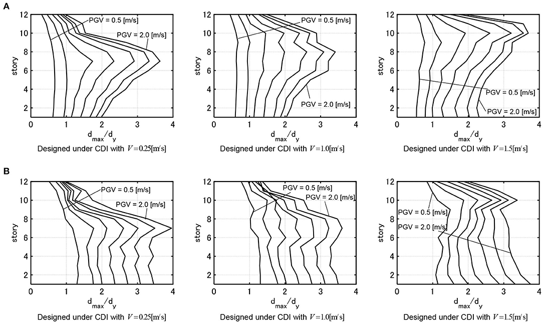
Figure 15. Maximum interstory drifts for amplified recorded ground motions, (A) Rinaldi Station FN (Northridge 1994), (B) Kobe Univ NS (Hyogoken-Nanbu 1995).
Conclusions
A new method for simultaneous optimal design of main building structures and viscous dampers is proposed for elastic-plastic MDOF building structures subjected to the critical double impulse which is regarded as a representative of the main part of near-fault ground motions. The main conclusions can be summarized as follows.
(1) An efficient sensitivity-based design algorithm was developed for the above-mentioned simultaneous optimal design problem of main structures and viscous dampers.
(2) The proposed optimal design algorithm works well-irrespective of the target value of the sum of damper damping coefficients and the input level of the critical double impulse. The setting of a larger number of nkc (nk = nc = 1 is preferable) causes a small effect of Wk0, Wc0 on the final design and leads to a favorable design.
(3) As the velocity level V used for the design becomes larger, the story stiffnesses in the lower stories become relatively large and those in the upper stories become relatively small. In this case, the interstory drifts in the upper stories increase much compared to the initial design and the those in the lower stories increase a little bit. As a result, the interstory drifts of all the stories are close to a uniform distribution for a large input. Furthermore, as the input velocity level used for the design becomes larger, the dampers concentrated to the lower stories spread into the middle and lower stories.
(4) While the model designed for V = 0.25[m/s] can reduce the maximum interstory drifts in the elastic response range, it exhibits a large deformation concentration in the middle and lower stories for the critical double impulse with larger input velocity level. This corresponds to the high yield-strength design. On the other hand, while the model designed for V = 1.5[m/s] exhibits larger elastic interstory drifts in the upper stories for the critical double impulse with smaller input velocity level, it shows a favorable interstory drift distribution for the critical double impulse with larger input velocity level by distributing the interstory drifts into the upper stories. This corresponds to the high limit-strength design.
(5) The maximum acceleration responses of the optimal elastic-plastic MDOF models with viscous dampers under the one-cycle sine waves corresponding to the critical double impulse do not depend on the input velocity levels of the critical double impulse used for design.
(6) The deformation characteristics for amplified recorded near-fault motions are similar to those for the critical double impulse. This guarantees the validity of using the critical double impulse for the simultaneous optimal design of main frames and passive dampers.
Data Availability Statement
The raw data supporting the conclusions of this article will be made available by the authors, without undue reservation.
Author Contributions
HA formulated the problem, conducted the computation, and wrote the paper. IT supervised the research and wrote the paper. Both authors contributed to the article and approved the submitted version.
Funding
Part of the present work was supported by the Grant-in-Aid for Scientific Research (KAKENHI) of Japan Society for the Promotion of Science (No.18H01584, JP20J20811). This support is greatly appreciated.
Conflict of Interest
The authors declare that the research was conducted in the absence of any commercial or financial relationships that could be construed as a potential conflict of interest.
References
Adachi, F., Yoshitomi, S., Tsuji, M., and Takewaki, I. (2013). Nonlinear optimal oil damper design in seismically controlled multi-story building frame. Soil Dyn. Earthq. Eng. 44, 1–13. doi: 10.1016/j.soildyn.2012.08.010
Akehashi, H., Kojima, K., Fujita, K., and Takewaki, I. (2018b). Critical response of nonlinear base-isolated building considering soil-structure interaction under double impulse as substitute for near-fault ground motion. Front. Built Environ. 4:34. doi: 10.3389/fbuil.2018.00034
Akehashi, H., Kojima, K., and Takewaki, I. (2018a). Critical response of SDOF damped bilinear hysteretic system under double impulse as substitute for near-fault ground motion. Front. Built Environ. 4:5. doi: 10.3389/fbuil.2018.00005
Akehashi, H., and Takewaki, I. (2019). Optimal viscous damper placement for elastic-plastic MDOF structures under critical double impulse. Front. Built Environ. 5:20. doi: 10.3389/fbuil.2019.00020
Akehashi, H., and Takewaki, I. (2020). Comparative investigation on optimal viscous damper placement for elastic-plastic MDOF structures: transfer function amplitude or double impulse. Soil Dyn. Earthq. Eng. 130:105987. doi: 10.1016/j.soildyn.2019.105987
ASCE (2017). Minimum Design Loads and Associated Criteria for Buildings and Other Structures, ASCE/SEI (Reston, VA).
Austin, M., and Pister, K. S. (1985). Design of seismic-resistant friction-braced frame. J. Struct. Eng. ASCE 111, 2751–2769. doi: 10.1061/(ASCE)0733-9445(1985)111:12(2751)
Aydin, E., Boduroglub, M. H., and Guney, D. (2007). Optimal damper distribution for seismic rehabilitation of planar building structures. Eng. Struct. 29, 176–185. doi: 10.1016/j.engstruct.2006.04.016
Bertero, V. V., Mahin, S. A., and Herrera, R. A. (1978). Aseismic design implications of near-fault San Fernando earthquake records, Earthq. Eng. Struct. Dyn. 6, 31–42. doi: 10.1002/eqe.4290060105
Castaldo, P., and De Iuliis, M. (2014). Optimal integrated seismic design of structural and viscoelastic bracing-damper systems. Earthq. Eng. Struct. Dyn. 43, 1809–1827. doi: 10.1002/eqe.2425
Cetin, H., Aydin, E., and Ozturk, B. (2019). Optimal design and distribution of viscous dampers for shear building structures under seismic excitations. Front. Built Environ. 5:90. doi: 10.3389/fbuil.2019.00090
Cimellaro, G. P. (2007). Simultaneous stiffness–damping optimization of structures with respect to acceleration, displacement and base shear. Eng. Struct. 29, 2853–2870. doi: 10.1016/j.engstruct.2007.01.001
Cimellaro, G. P., and Retamales, R. (2007). Optimal softening and damping design for buildings. Struct. Control Health Monit. 14, 831–857. doi: 10.1002/stc.181
Cimellaro, G. P., Soong, T. T., and Reinhorn, A. M. (2009). Integrated design of inelastic controlled structural systems. Struct. Control Health Monit. 16, 689–702. doi: 10.1002/stc.314
Dargush, G. F., and Sant, R. S. (2005). Evolutionary aseismic design and retrofit of structures with passive energy dissipation. Earthq. Eng. Struct. Dyn. 34, 1601–1626. doi: 10.1002/eqe.497
Domenico, D. D., Ricciardi, G., and Takewaki, I. (2019). Design strategies of viscous dampers for seismic protection of building structures: a review. Soil Dyn. Earthq. Eng. 118, 144–165. doi: 10.1016/j.soildyn.2018.12.024
Garcia, D. L. (2001). A simple method for the design of optimal damper configurations in MDOF structures, Earthq. Spectra 17, 387–398. doi: 10.1193/1.1586180
Garcia, D. L., and Soong, T. T. (2002). Efficiency of a simple approach to damper allocation in MDOF structures. J. Struct. Control. 9, 19–30. doi: 10.1002/stc.3
Hashizume, S., and Takewaki, I. (2020). Hysteretic-viscous hybrid damper system with stopper mechanism for tall buildings under earthquake ground motions of extremely large amplitude. Front. Built Environ. 6:583543. doi: 10.3389/fbuil.2020.583543
Idels, O., and Lavan, O. (2020). Optimization based seismic design of steel moment resisting frames with nonlinear viscous dampers. Struct. Control Health Monit. e2655. doi: 10.1002/stc.2655
Khansefid, A., and Bakhshi, A. (2019). Advanced two-step integrated optimization of actively controlled nonlinear structure under mainshock–aftershock sequences. J. Vib. Control. 25, 48–62. doi: 10.1177/1077546318795533
Khansefid, A., Maghsoudi-Barmi, A., and Bakhshi, A. (2019). “Seismic performance assessment of optimally designed base isolation system under mainshock-aftershock sequences,” in 8th International Conference on Seismology and Earthquake Engineering (Tehran).
Kojima, K., and Takewaki, I. (2015). Critical earthquake response of elastic-plastic structures under near-fault ground motions (Part 1: Fling-step input). Front. Built Environ. 1:12. doi: 10.3389/fbuil.2015.00012
Lavan, O., and Avishur, M. (2013). Seismic behavior of viscously damped yielding frames under structural and damping uncertainties. Bull. Earthq. Eng. 11, 2309–2332. doi: 10.1007/s10518-013-9479-7
Lavan, O., and Dargush, G. F. (2009). Multi-objective evolutionary seismic design with passive energy dissipation systems. J. Earthq. Eng. 13, 758–790. doi: 10.1080/13632460802598545
Lavan, O., and Levy, R. (2006). Optimal design of supplemental viscous dampers for linear framed structures. Earthq. Eng. Struct. Dyn. 35, 337–356. doi: 10.1002/eqe.524
Murakami, Y., Noshi, K., Fujita, K., Tsuji, M., and Takewaki, I. (2013). Simultaneous optimal damper placement using oil, hysteretic and inertial mass dampers. Earthq. Struct. 5, 261–276. doi: 10.12989/eas.2013.5.3.261
Palermo, M., Silvestri, S., Landi, L., Gasparini, G., and Trombetti, T. (2018). A “direct five-step procedure” for the preliminary seismic design of buildings with added viscous dampers. Eng. Struct. 173, 933–950. doi: 10.1016/j.engstruct.2018.06.103
Saotome, Y., Kojima, K., and Takewaki, I. (2018). Earthquake response of 2DOF elastic-perfectly plastic model under multiple impulse as substitute for long-duration earthquake ground motions. Front. Built Environ. 4:81. doi: 10.3389/fbuil.2018.00081
Shiomi, T., Fujita, K., Tsuji, M., and Takewaki, I. (2018). Dual hysteretic damper system effective for broader class of earthquake ground motions. Int. J. Earthq. Impact Eng. 2, 175–202. doi: 10.1504/IJEIE.2018.093391
Silvestri, S., and Trombetti, T. (2007). Physical and numerical approaches for the optimal insertion of seismic viscous dampers in shear-type structures. J. Earthq. Eng. 11, 787–828. doi: 10.1080/13632460601034155
Singh, M. P., and Moreschi, L. M. (2001). Optimal seismic response control with dampers. Earthq. Eng. Struct. Dyn. 30, 553–572. doi: 10.1002/eqe.23
Singh, M. P., and Moreschi, L. M. (2002). Optimal placement of dampers for passive response control. Earthq. Eng. Struct. Dyn. 31, 955–976. doi: 10.1002/eqe.132
Takewaki, I. (1997). Optimal damper placement for minimum transfer functions. Earthq. Eng. Struct. Dyn. 26, 1113–1124.
Takewaki, I. (1999). Displacement–acceleration control via stiffness–damping collaboration. Earthq. Eng. Struct. Dyn. 28, 1567–1585.
Takewaki, I. (2009). Building Control with Passive Dampers: -Optimal Performance-Based Design for Earthquakes. Singapore: John Wiley & Sons Ltd. doi: 10.1002/9780470824931
Takewaki, I. (2013). Critical Excitation Methods in Earthquake Engineering. Oxford: Butterworth-Heinemann. doi: 10.1016/B978-0-08-099436-9.00012-2
Uetani, K., Tsuji, M., and Takewaki, I. (2003). Application of optimum design method to practical building frames with viscous dampers and hysteretic dampers. Eng. Struct. 25, 579–592. doi: 10.1016/S0141-0296(02)00168-2
Vamvatsikos, D., and Cornell, C. A. (2001). Incremental dynamic analysis. Earthq. Eng. Struct. Dyn. 31, 491–514. doi: 10.1002/eqe.141
Whittle, J. K., Williams, M. S., Karavasilis, T. L., and Blakeborough, A. (2012). A comparison of viscous damper placement methods for improving seismic building design. J. Earthq. Eng. 16, 540–560. doi: 10.1080/13632469.2011.653864
Keywords: simultaneous optimization of structure and damper, double impulse, earthquake response, critical excitation, elastic-plastic response, viscous damping
Citation: Akehashi H and Takewaki I (2020) Simultaneous Optimization of Elastic-Plastic Building Structures and Viscous Dampers Under Critical Double Impulse. Front. Built Environ. 6:623832. doi: 10.3389/fbuil.2020.623832
Received: 30 October 2020; Accepted: 17 November 2020;
Published: 09 December 2020.
Edited by:
Ehsan Noroozinejad Farsangi, Graduate University of Advanced Technology, IranReviewed by:
Saeed Dehghani, Shiraz University, IranAli Khansefid, K. N. Toosi University of Technology, Iran
Copyright © 2020 Akehashi and Takewaki. This is an open-access article distributed under the terms of the Creative Commons Attribution License (CC BY). The use, distribution or reproduction in other forums is permitted, provided the original author(s) and the copyright owner(s) are credited and that the original publication in this journal is cited, in accordance with accepted academic practice. No use, distribution or reproduction is permitted which does not comply with these terms.
*Correspondence: Izuru Takewaki, dGFrZXdha2lAYXJjaGkua3lvdG8tdS5hYy5qcA==