 M. Ammar Alzarrad
 Gary P. Moynihan2
 Mayuri Mehra
- 1Department of Civil Engineering, Marshall University, Huntington, WV, United States
- 2Department of Civil, Construction and Environmental Engineering, University of Alabama, Tuscaloosa, AL, United States
- 3Estimating Department, Kiewit Power Constructors, Lenexa, KS, United States
- 4Virtual Design and Construction Department, Project Controls Cubed, Laguna Beach, CA, United States
With the BIM applications on fast-track, it is being used for new construction and recently being utilized for renovation, retrofitting, and repairing purposes. Although many studies have been conducted to identify BIM capabilities in renovation projects, the application of 4D BIM for both the demolition and the construction phases of renovation projects is still underdeveloped. This paper presents a guideline to apply 4D BIM for complicated renovation projects that include demolition and construction phases. The paper represents a step-by-step process from the extraction of information from a 2D model and converting it into a 4D model. The proposed guideline will help CAD users to apply 4D BIM for complicated renovation model. A real case application is analyzed to demonstrate the potential of the presented guideline. The research results show that the proposed guideline could assist in construction management by finding out inappropriate sequences in schedule, conducting evaluation of issues related to constructability, and identifying disagreements in time and space. The proposed guideline could help identify errors in construction scheduling, which have the potential to reduce project cost and duration.
Introduction
Renovation is a common way of maintaining buildings in order to serve their users. For example, the maintenance of campus buildings is vital because they serve many students during their education and serve as a workplace for professors and administrative staff. The key purpose of building renovations is to control deterioration and maintain each building component (Farahani et al., 2019). In practice, taking the case of the university campus as an example, campus buildings may be subject to a wide range of complex defects, such as peeling paint, wall cracks, and ceiling cracks (Frangopo et al., 2004). Renovation design on campus does not depend only on technical needs but also on providing a strategy to achieve several objectives and often conflicting under resource constraints.
The main feature that influences the complexity of renovation projects is the concurrent use of a building by both workers and users. It is usually not possible to close a whole building to carry out a single-phase renovation project (Bakri et al., 2017). Also, there are possibly conflicting activities between the construction crew and occupants. To address this problem, a renovation project is generally carried out in a number of segments in different time periods or locations. As a result, it can decrease the undesirable impact on occupants, and the renovation activity can be performed as expected (Bakri et al., 2017). Renovation projects usually include multiple decision factors. By concentrating on the building conditions, many elements affect the type of renovation, such as the building age, the urgency to repair the building, and the building's service life. As a result of the many affecting factors, the decision of the type of renovation made by the planner can be diverse and can impact the entire renovation project in various ways (Lee, 2012). Therefore, a strategy to assess the appropriate schedule is required. Visualization techniques such as 4D BIM could help identify errors in the renovation schedule which will help planners produce a more accurate plan. This paper provides step-by-step guidance for CAD users to apply 4D BIM for renovation projects. The paper is paving the way to the future application of 4D BIM in renovation buildings.
Literature Review
In the late 20th century, it was estimated that by utilizing the full potential of computers, engineers would be able to design in 3D as well as 4D models (Azlan, 2018). Coming into the 21st century, 3D design is being used extensively. The concept of BIM has emerged, which is much more than simply 3D design. Building Information Modeling (BIM) is simply a process for creating and managing all of the information in a project whether it be before, during or after construction. With BIM, a digital, intelligent model of a building is developed virtually. After linking the 3D BIM model elements to the time factor, a 4D model can be created, which allows visualization and analysis of the sequence of activities for the construction (Sampaio, 2017). In what follow, the researchers will summarize the history of 4D BIM models and then discuss the 4D BIM models for renovation projects.
History of 4D BIM Models
Shiue et al. (2019) argued that planners in construction usually interpret 2D or 3D drawings and specifications to generate sequential relationships of activities in the schedule. In doing so, they stated that the project stakeholders, including contractor, client, and designer have to generate the physical building by mental association of the schedule information, which represents the integration of time and space. 4D model facilitates the generation of a 4D movie, representing the relationship between 3D model and schedule information, and removes the cumbersome mental visualization task (Shiue et al., 2019).
Kamari et al. (2019) have stated that the planners generally used CPM-based networks and bar charts in the construction industry to recognize the project schedule (Kamari et al., 2019). In doing so, they identified that it was difficult to associate each component in 2D drawing to its corresponding activity, especially if the interpreters have limited experience in construction. In addition, the use of 4D model made it easier to identify errors such as inconsistency in level of detail of schedule, missing activities in schedule, logic of schedule, and conflicts of time and space. In summary, 4D model facilitates engineers to visualize the planning information such that it prevents the need of conceptualization and simply understands the problems associated with the schedule (Kamari et al., 2019).
4D also provides support to site personnel to efficiently coordinate equipment space requirements than conventional CPM networks and 2D site layouts (Mahalingam et al., 2010). Webb et al. (2004) mentioned that visualization has been relatively common use of 4D. They gave an example of Bovis Lend Lease Company that deployed 4D across several market sectors and projects all over the world (Webb et al., 2004). Hartmann et al. (2008) described various application areas of 3D/4D modeling and also gave an assessment of each application area. Those areas of application of 3D/4D modeling are photorealistic renderings, virtual design review, analyzing design options/building operations, cost estimating, analyzing construction operations, construction document production, and bid package preparation (Hartmann et al., 2008).
Russell et al. (2009) conducted a research to figure out the current virtual construction practice in the United Kingdom. The research found that there was a high level of recognition for 4D planning. Visualization of construction processes was the highest-scoring category when it comes to improvement over traditional planning by 4D modeling (Russell et al., 2009). Umar et al. (2015) concluded that use of 4D BIM is increasing in the Architecture, Engineering, and Construction (AEC) industry (Umar et al., 2015). To aid that, significant contribution has been made in the research to facilitate passing of 4D simulation from Navisworks to a Virtual Reality (VR) platform, which is an important step for technological sophistication in construction industry (Boton, 2018).
In another research conducted of construction industry professionals by Swallow and Zulu (2018), the study showed that 70% of directors/managers, 74% of professionals knew about 4D while average of 31.2% of participants said they adopted 4D modeling in work. One of the main benefits of 4D modeling was found to be added value via visualization (Swallow and Zulu, 2018).
BIM Models for Renovation Projects
BIM in today’s modern world has given insight to many engineering professionals in design, construction, and maintenance and management of building infrastructure. According to research done for renovation using BIM, the time required to deliver a BIM model is 14 times faster than a conventional CAD drafting. This study was conducted by creating an architectural 3D model of Residential Bungalow using Revit and integrating its schedule with the help of Microsoft Project (4D). The model was then analyzed for any clashes using Navisworks. A 2D model for same building was also created using AutoCAD. The 4D model created was used for cost planning (5D). Comparative analysis was run for both these models by comparing time required to complete conventional drawing against the BIM model, which showed that the BIM model is time effective and more accurate than the 2D drawing and can be adjusted according to the requirements easily (Wang et al., 2014).
For a pilot housing reconstruction project in Ukraine, a 3D model was developed based on GIS property survey and utilization of BIM technology. The method adopted was to include individual building systems for major renovation, modernization and reconstruction work in a common model, organizing cost estimates, selecting contractors, and project deadlines as part of the project. In addition to this, formation of electronic passport for structural elements and utility payments were assumed. With the BIM project, the project was exact, transparent, economical flexible, and easy to be replicated by other renovation projects. This project highlighted the benefits of cost-oriented arrangements of construction activities in BIM technology. If the project is based on reliable information, project teamwork and decision-making BIM can facilitate design and renovation process by automated simulation of cost-activity information (Siniak et al., 2019).
A similar study was conducted for a refurbishment project in New Zealand which shows that recovery and resistance from error are easier and faster for a BIM model than traditional methods. The BIM model developed for this research included combination of time and resources, management and alignment, regulations and standard, construction policies, energy-efficient measures for refurbishment, interoperability, coordination of services, economic payback of tools, and client’s expectation of on-time delivery and payback period. The collaborative relationship between stakeholders such as contractors and subcontractors obtained through BIM implementation improved the project's cost and quality savings. Propagation of errors in different directions using BIM resulted in quick recovery of the project's errors and uncertainties (Okakpu et al., 2019).
In a research done by Whyte (2003) on the use of BIM for renovation projects it was found that implementing BIM in technical, organizational and numerical fields of construction can significantly generate a better turnover for the construction industry. The research focuses on the conservation of historic buildings by clarifying the scope such as rehabilitation, restoration, renovation, conserving or preservation. One of the major issues observed was the incompleteness of available data and information to convert the renovation sector to BIM (Whyte, 2003).
A study in Seoul, South Korea showed the efficacy of the BIM-parametric framework in developing in-situ, sustainable renovation strategies for aged buildings to improve indoor visual comfort. The methodology used was virtual construction of exemplary apartment building located on Seoul using Autodesk Revit. Component families were created to store construction data obtained from existing buildings. Ladybug tools and Rhinoceros Grasshopper 0.9 were used for energy and daylight simulation and plug-in for parametric suite. Properties of building components and materials used for environment simulation was exported from BIM model and Microsoft Excel 2017. The study focused on virtual construction using BIM, climate and solar radiation analysis of the building, building envelope analysis and virtual comfort analysis (Zhang et al., 2016).
With data collection being one of the major concerns in implementing BIM for renovation of existing structures it becomes important to find out a way that would ease the process of finding data in real time. Arayici (2008) suggested the use of point cloud data editing or CAD extraction process which would fulfill the initial data requirements for creating a BIM model. The suggestion included workflow of lining up the model, plane insertion, vertices selection, optimizing mesh model, generating and exporting cross-sections and creating a 3D CAD model (Arayici, 2008). The software, instruments and techniques utilized included Riegl LMS Z210 scanner, software RiSCANPro, IMMerge Module of Polyworks software, 3D CAD and Microstation Triforma software. The study concluded that BIM can be achieved for existing structures using 3D laser scanners which helps in producing BIM models. These BIM models can help build design, planning, refurbishment, effective heritage documentation, VR modeling, disaster management, sophisticated environment simulation, and achieving long-term sustainable built environments for living and working. Helander and Singh (2016) conducted three case studies where BIM was used in different renovation phases like design phase, clash detection, and construction phase. Two inventory models were created for managing the initial information, one being a structural model with must-have level of useful minimum principle and the other being a space model for managing building information with should have level of information. The study covered information needed to create a model and results showed that models are much easier to understand. A well-documented model can help attain a remarkable level of accuracy that can be divided between the stakeholders (Helander and Singh, 2016).
In a related study in building maintenance, Farahani et al. (2019) argued that the effects of renovations would improve the quality and extend the building's service life. In this study, the quality of building space to be used is the first item that would affect the building's performance index. Farahani used a BIM based approach to estimate the performance index of the building (Farahani et al., 2019). Kamari et al. (2017) developed a decision support framework as a renovation “knowledge base” with the aim of managing the complexity of decision problems regarding the selection and use of various renovation alternatives. Kamari et al. classify renovation intervention into four levels, i.e., minor, moderate, deep, and nearly zero-energy buildings (NZEB) (Kamari el al., 2017).
With the applications of BIM on fast-track, it is being used for new construction and recently being utilized for renovation, retrofitting, and repairing purposes. Although many studies have been conducted to identify BIM capabilities in renovation projects, the application of 4D BIM for both the demolition and the construction phases of renovation projects is still underdeveloped. This paper presents a guideline to apply 4D BIM for complicated renovation projects that include both demolition and construction phases. The paper represents a step-by-step guideline from the extraction of information from a 2D model and converting it into a 4D model. The proposed guideline will help CAD users to apply 4D BIM for complicated renovation model. The next section will discuss the proposed guideline details.
A Process Guideline
This section will explain the proposed guideline in detail. The guideline includes four steps and step number four is broken down into three stages. Step One discusses the 3D model creation, Step Two discusses creating a schedule, Step Three discusses matching the 3D model and the schedule. Finally, Step Four discusses the creation of the 4D model.
Step One (Code 001): Create a 3-D Model of the Project
For any renovation project there is a possibility that some of the information may not be available in order to start with. When floor plans or 2D models are available they can be converted into 3D model using Revit or other software. In case 2D or 3D models are not available (i.e., heritage buildings), 3D laser scanning can be used to collect spatial locations of various points and obtain coordinate points to regenerate a 3D model.
Step Two (Code 002): Create a Schedule Data of the Project
It is required for any construction project to have schedule of all the activities and events involved to be in proper format in order to proceed with further detailing. Schedule for the renovation project can be generated using MS Project or Primavera P6 which is a simple process of feeding schedule dates of the activities involved in renovation project to the software and creating activity profile and Gant Chart using that information. Schedule of existing building which is available in .pdf format has to be manually input in MS Excel workbook excluding unnecessary data like project milestone/interface, procurement, late start, and late finish dates. Also, activities related to demolition/construction like backfilling, compacting, finishing works, steel works should be added or modified. Now that the schedule has been filtered it can be converted to .csv format, which is simple a variation of MS Excel file (.xlsx).
Step Three (Code 003): Divide the 3-D Model Into Levels and Zones to Match the Schedule Activities
In this module the 3D Revit file (rvt.) should be exported to Industry Foundation Classes (IFC) format and then divided into levels and zones. Revit supports IFC files for import as well as export. This becomes useful when it is required to export Revit files to other software or applications that do not support .rvt files and vice versa. IFC feature of Revit provides another benefit of division by levels for 4D simulation. This can be done while exporting Revit file when a dialogue box appears which has an option to divide by levels. Zones are divided automatically in Revit. As an alternative, the 3D model could be divided initially during Module One.
Step Four (Code 004): Integrate The 3-D Model and The Schedule
This step consists of three stages; develop selection sets, link project tasks with selection sets, simulate the 3D model with its time associations.
Stage One (Code 004.1): Develop Selection Sets
In this stage, the schedule can be imported into Navisworks and viewed under Selection Tree Palette, where different model components can be viewed. In sets palette below Selection Tree palette, set of elements in 3D model can be grouped as a set with suitable name. The element can be linked using either selection set or search set, with the schedule depending upon the size of elements and their repetition.
Stage Two (Code 004.2): Link Project Tasks With Selection Sets
New task/activities can be added in this stage so that software can recognize elements that need to be demolished/renovate. All activities should be linked to the model so that model can identify the difference between activities associated with the existing structure and the structure to be constructed/demolished. The schedule of to-be-demolished structure should be assigned manually and adjusted to be recognized by the software.
Stage Three (Code 004.3): Simulate the 3-D Model With Its Time Associations
Configuration and simulation settings (i.e., start dates, end dates, interval size, playback durations): should be adjusted in Navisworks to match the schedule. Interval size and Playback duration should be set as per convenience. It is recommended to use 5% interval size and playback duration between 15 and 40 s (Moreno et al., 2019). This generates the initial simulation 4D model. Figure 1 shows the four steps of the proposed guideline.
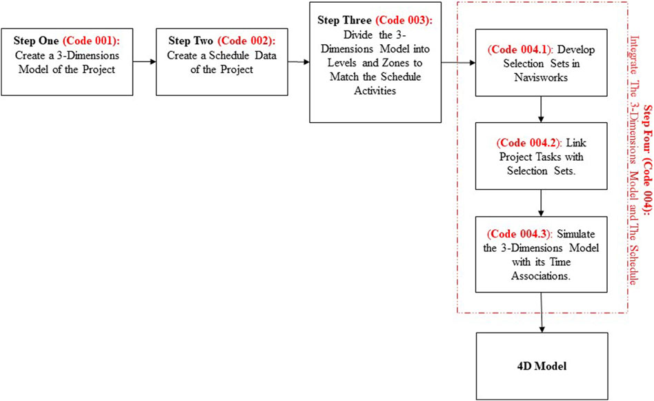
FIGURE 1. The proposed guideline workflow.
Case Study
In order to demonstrate the potential of the presented guideline, the renovation project of H.M. Comer Hall, the administrative building of The College of Engineering at the University of Alabama has been analyzed. In this project, 3D Model of H.M. Comer Hall is used with the real preliminary project schedule for the same building. Acquisition of 3D Model is in the form of Autodesk Revit file (.rvt). The same software program is used to access and modify the required information. As BIM-based software, Revit file can be shared across various similar platform. Similarly, PDF file of the preliminary schedule is entered into MS Excel file for use in the project. Ultimately, Autodesk Navisworks Manage software program is used to integrate the 3D BIM file with spreadsheet file to generate the construction simulation model.
According to The University of Alabama, H.M. Comer Hall dates back to 1962, when it opened in The University of Alabama as the Mineral Industries Building. A substantial change to the building’s east section was made in 2012, when a portion of wings extended to the east was removed for the development of NERC building. Going through 18 months of major renovation, it opened in August 2018 as the administration of College of Engineering. Before major renovation, H.M. Comer Hall structure was a concrete frame made up of concrete slab and concrete joist system with concrete beam around its perimeter. Masonry and brick made up the external cladding of the building. The renovation project comprised both internal as well as external work. The main objective of the renovation work is to replace the building systems but maintaining the existing concrete structural frame structure of the building. Figure 2 shows the H.M. Comer Hall before and after the renovation.
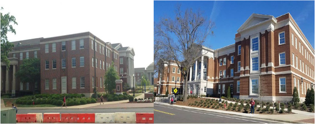
FIGURE 2. H.M. Comer Hall prior to renovation (on the left) vs. H.M. Comer Hall after renovation (on the right).
The first step to apply the presented guideline (Code 001) is to get 3D model for the H.M. Comer Hall renovation project, as shown in Figure 3.
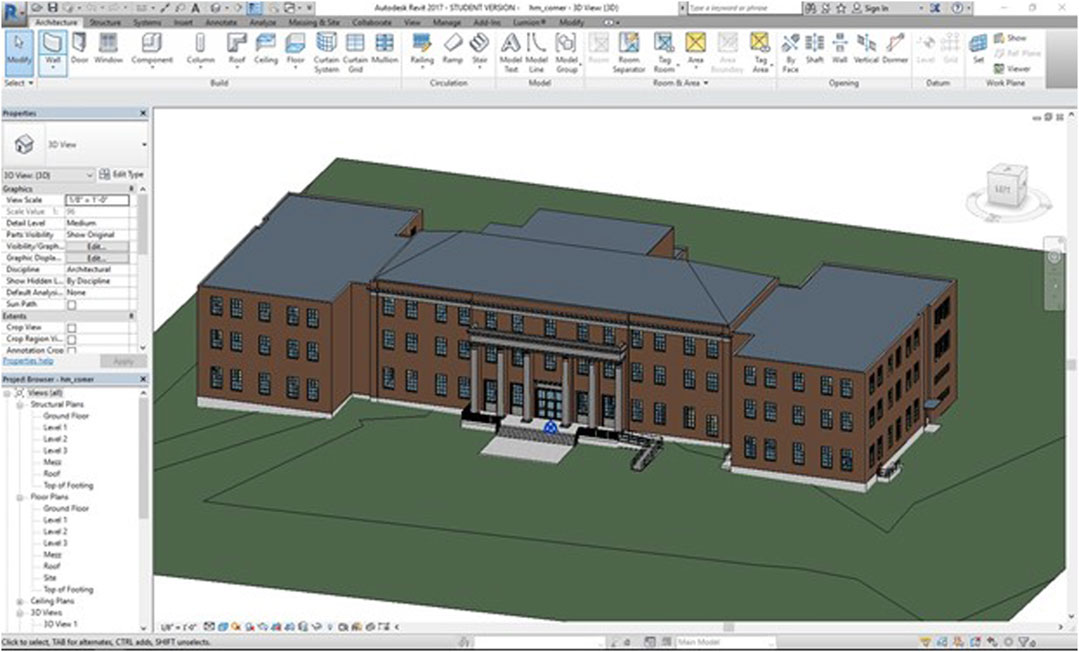
FIGURE 3. 3D model of H.M. Comer Hall in Revit 2017.
The second step in the presented guideline (Code 002) is to get the H.M. Comer Hall project schedule. The format obtained for the project schedule is .pdf, which can be seen in Figure 4. In this case, the schedule will be entered manually into an Excel sheet and saved as a (.csv) file format.
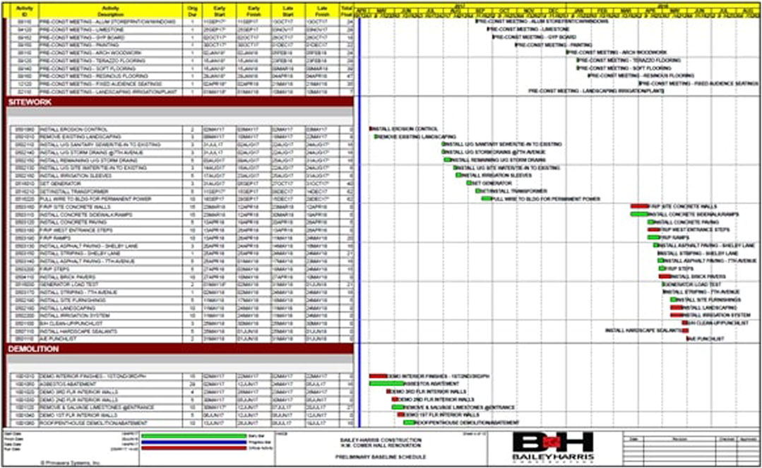
FIGURE 4. Snapshot of Project Schedule for H.M. Comer Hall renovation in PDF format.
Step Three (Code 003) is to modify the 3D model to match the activities on the schedule. The first step in the modification process is the identification of sub-grouping of activities in the project schedule. According to the proposed guideline, the building elements should be sub-grouped based on levels and zones. Consequently, building wall envelope, interior walls, and components are modified to be easily linked to schedule activities in Navisworks Manage.
Stage One of Step Four (Code 004.1) of the proposed guideline is to import the 3D Revit file (rvt. format) and the schedule file (.csv format) into Navisworks to develop selection sets. A selection set is grouping model elements selected directly in the model space by using the mouse pointer. This gives the user freedom to select desired model elements according to the corresponding activity. Figure 5 shows Navisworks Manage and the integration process of the 3D model and schedule.
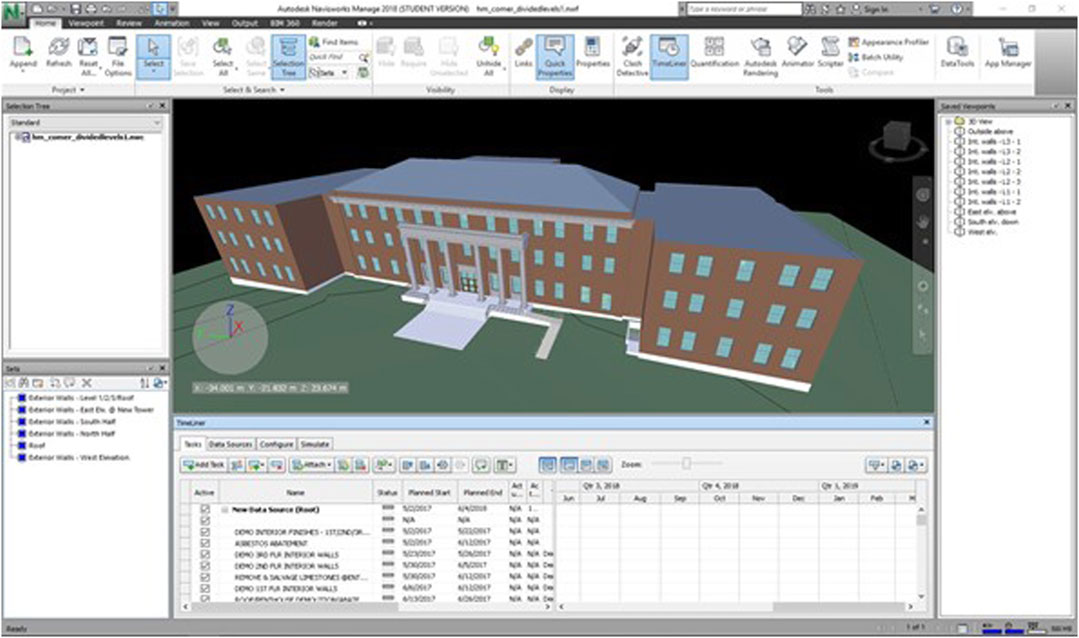
FIGURE 5. Navisworks Manage and the integration process of the 3D model and schedule.
The second stage of Step Four (Code 004.2) is to link the task/activity to the corresponding selection set. This is done by using the Timeliner function in Navisworks. The last stage of Step Four (Code 004.3) is to simulate the 3-D model with its time associations. The created 4D model is similar to blown up 3D model, where the model elements either phase out or build depending on the phase of construction. By analyzing the simulation snapshots, it is seen that some elements are red while others are green at different points in time. Day 24-Week 4 is the simulation model view from front (west), where the roof is transparent red color along with building envelope in south wing. This indicates that early demolition of exterior wall begins from south wing, which is verified from project schedule. It is also noticeable that the interior walls are missing in third floor. However, the structural columns are intact. Figure 6 shows a snapshot of Day 24-Week 4 simulation.
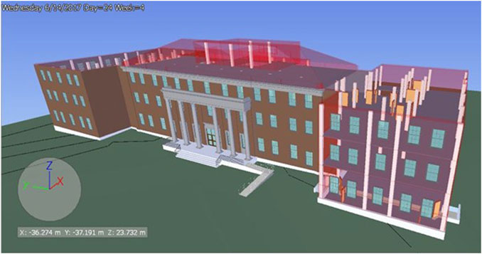
FIGURE 6. A snapshot of Day 24-Week 4 simulation.
Similarly, Day 39-Week 6 is a view from back (east). Within two weeks, south wing, north wing, and eastern portion is under full demolition while the roof is under construction. This is indicated by transparent green color see in the roof. Figure 7 shows a snapshot of 39-Week 6 simulation.
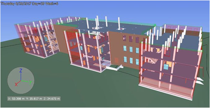
FIGURE 7. A snapshot of 39-Week 6 simulation.
In Day 120-Week 18, construction of south wing exterior wall is completed while west elevation wall and north wing wall is under construction. Roof construction is complete. Day 148-Week 22 is the back view (east) of the simulation model. While all the exterior walls in the building has been constructed, eastern portion is under construction. This indicates that it has been intentionally schedule such that this part begins after the completion of other parts. Figures 8 and 9 show a snapshot of Day 120-Week 18 and Day 148-Week 22 simulations, respectively.

FIGURE 8. A snapshot of Day 120-Week 18 simulation.
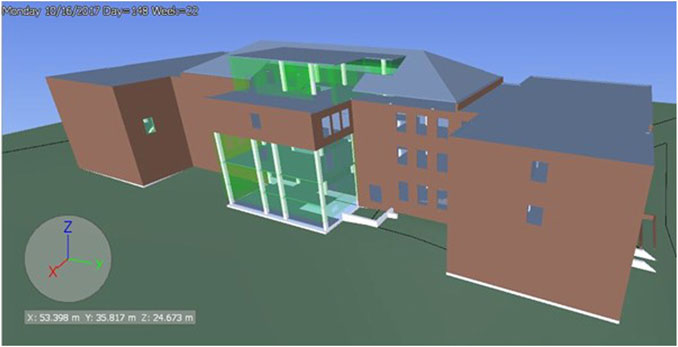
FIGURE 9. A snapshot of Day 148-Week 22 simulation.
Conclusion
This paper provides step-by-step guidance for CAD users to apply 4D BIM for renovation model. The guideline represents a step-by-step process from extraction of information from a 2D model and converting it into a 4D model. The paper is paving the way to future application of the proposed guideline on renovation buildings. A real case application is analyzed to demonstrate the potential of the presented guideline. The case analysis shows the 4D visualization of construction process of H.M. Comer Hall renovation over its entire project duration. It is presented in this research in the form of images, which are snapshots of the simulation model at different points of interest. H.M. Comer Hall renovation project is a peculiar project for 4D simulation, as it consists of demolition phase along with construction phase. This shows that the proposed guideline is suitable for complicated projects that includes both demolition and construction phases. The research results show that the proposed guideline could assist in construction management by finding out inappropriate sequences in schedule, conducting evaluation of issues related to constructability, and identifying disagreements in time and space. Even though this study provides a guideline to CAD users and planners, the concept of this study is subject to limitations. There are two main limitations in this study that need to be considered: First, the study has been applied on a single renovation project, whereas the application might differ in case the project has a different nature, or in case the project documents are missing, and laser scanning shall be applied. Second, the case study 3D model consists of architectural and structural elements only and does not include other elements such as mechanical, electrical, and plumbing. Future improvement could be applying the proposed guideline on an old historical building where laser scanning needs to be used.
Data Availability Statement
The original contributions presented in the study are included in the article/Supplementary Material, further inquiries can be directed to the corresponding author.
Author Contributions
All authors listed have made a substantial, direct and intellectual contribution to the work, and approved it for publication.
Funding
The research leading to the publication of this article was partially supported by the Department of Civil Engineering at Marshall University in Huntington, West Virginia, United States of America.
Conflict of Interest
AP is employed by the company Kiewit Power Constructors. MM is employed by the company Project Controls Cubed.
The remaining authors declare that the research was conducted in the absence of any commercial or financial relationships that could be construed as a potential conflict of interest.
References
Arayici, Y. (2008). Towards building information modelling for existing structures. Struct. Surv. 26 (3), 210–222. doi:10.1108/02630800810887108
Azlan, S. A. (2018). Cost performance of building refurbishment works: the case of Malaysia. Int. J. Build. Pathol. Adapt. 36 (3), 41–62. doi:10.3390/su11195542
Bakri, N. N. O., Malaysia, M. U. S., and Mydin, M. A. O. (2017). General building defects: causes, symptoms and remedial wor. Eur. J. Technol. Des. 3 (3), 4–17. doi:10.5897/JCECT2019.0498
Boton, C. (2018). Supporting constructability analysis meetings with Immersive Virtual Reality- based collaborative BIM 4D simulation. Automat. Construct. 96 (10), 1–15. doi:10.1016/j.autcon.2018.08.020
Farahani, A., Wallbaum, H., and Dalenbäck, J. O. (2019). Optimized maintenance and renovation scheduling in multifamily buildings: a systematic approach based on condition state and life cycle cost of building components. Constr. Manag. Econ. 37 (5), 139–155. doi:10.1080/01446193.2018.1512750
Frangopo, D. M., Kallen, M. J., and Van Noortwijk, J. M. (2004). Probabilistic models for life-cycle performance of deteriorating structures: review and future directions. Prog. Struct. Eng. Mater. 6 (4), 197–212. doi:10.1002/pse.180
Hartmann, T., Gao, J., and Fischer, M. (2008). Areas of application for 3D and 4D models on construction projects. J. Constr. Eng. Manage. 134 (10), 776–785. doi:10.1061/(asce)0733-9364(2008)134:10(776)
Helander, D., and Singh, V. (2016). BIM in building renovation projects: what is the useful minimum information requirement?. Int. J. Product Lifecycle Manag. 9 (1), 22–35. doi:10.1504/ijplm.2016.078863
Kamari, A., Corrao, R., and Kirkegaard, P. H. (2017). Sustainability focused decision-making in building renovation. Int. J. Sustain. Built Environ. 1 (1), 330–350. doi:10.1016/j.ijsbe.2017.05.001
Kamari, A., Schultz, C. P. L., and Kirkegaard, P. H. (2019). Constraint-based renovation design support through the renovation domain model. Automat. Construct. 104 (2), 265–280. doi:10.1016/j.autcon.2019.04.023
Lee, H.-Y. (2012). Renovation scheduling to minimize user impact of a building that remains in operation. Automat. Construct. 22 (2), 398–405. doi:10.1016/j.autcon.2011.09.018
Mahalingam, A., Kashyap, R., and Mahajan, C. (2010). An evaluation of the applicability of 4D CAD on construction projects. Automat. Construct. 19 (2), 148–159. doi:10.1016/j.autcon.2009.11.015
Moreno, C., Olbina, S., and Issa, R. (2019). BIM use by architecture, engineering, and construction (AEC) industry in educational facility projects. Hindawi Adv. Civil Eng. 26, 684. doi:10.1155/2019/1392684
Okakpu, A., Hoseini, A. G., Tookey, J., and Li, P. (2019). An optimization process to motivate effective adoption of BIM for refurbishment of complex buildings in New Zealand. Front. Architect. Res. (8), 646–661. doi:10.1016/j.foar.2019.06.008
Russell, A., Staub-French, S., Tran, N., and Wong, W. (2009). Visualizing high-rise building construction strategies using linear scheduling and 4D CAD. Automat. Construct. 18 (2), 219–236. doi:10.1016/j.autcon.2008.08.001
Sampaio, A. Z. (2017). BIM as a computer-aided design methodology in Civil engineering. J. Softw. Eng. Appl. 10 (02), 194–210. doi:10.4236/jsea.2017.102012
Shiue, F., Zheng, M., Lee, H., Khitam, A. F., and Li, P. (2019). Renovation construction process scheduling for long-term performance of buildings: an application case of university campus. Sustainab. J. 11, 542. doi:10.3390/su11195542
Siniak, N., Źróbek, S., Nikolaiev, V., and Shavrov, S. (2019). Building information modeling for housing renovation - example for Ukraine. Real Estate Manag. Valuat. 27 (2), 97–107. doi:10.2478/remav-2019-0018
Swallow, M. R., and Zulu, S. (2018). Benefits and barriers to the adoption of 4D modelling for site health and safety management. Front. Built Environ. 4 (4), 86–99. doi:10.3389/fbuil.2018.00086
Umar, U. A., Shafiq, N., Malakahmad, A., and Haupt, T. C. (2015). 4D BIM application in AEC industry: impact on integrated project delivery. Res. J. Appl. Sci. Eng. Technol. 10 (5), 547–552. doi:10.19026/rjaset.10.2462
Wang, W.-C., Weng, S.-W., Wang, S.-H., and Chen, C.-Y. 2014). Integrating building information models with construction process simulations for project scheduling support. Automat. Construct. 37 (5), 68–80. doi:10.1016/j.autcon.2013.10.009
Webb, R. M., Smallwood, J., and Haupt, T. C. (2004). The potential of 4D CAD as a tool for construction management. J. Construct. Res. 5 (1), 43–60. doi:10.1142/s1609945104000048
Whyte, J. (2003). Innovation and users: virtual reality in the construction sector. Construct. Manag. Econ. 21 (6), 565–572. doi:10.1080/0144619032000113690
Keywords: Bim, 4D, visualization, renovation projects, simulation
Citation: Alzarrad MA, Moynihan GP, Parajuli A and Mehra M (2021) 4D BIM Simulation Guideline for Construction Visualization and Analysis of Renovation Projects: A Case Study. Front. Built Environ. 7:617031. doi: 10.3389/fbuil.2021.617031
Received: 13 October 2020; Accepted: 19 February 2021;
Published: 24 March 2021.
Edited by:
Zhen Chen, University of Strathclyde, United KingdomReviewed by:
Laila Khodeir, British University in Egypt, EgyptPhui Fung Wong, Tunku Abdul Rahman University, Malaysia
Copyright © 2021 Alzarrad, Moynihan, Parajuli and Mehra. This is an open-access article distributed under the terms of the Creative Commons Attribution License (CC BY). The use, distribution or reproduction in other forums is permitted, provided the original author(s) and the copyright owner(s) are credited and that the original publication in this journal is cited, in accordance with accepted academic practice. No use, distribution or reproduction is permitted which does not comply with these terms.
*Correspondence: M. Ammar Alzarrad, YWx6YXJyYWRAbWFyc2hhbGwuZWR1