 Blaž Zoubek
 Anže Babič
 Tatjana Isaković
- Faculty of Civil and Geodetic Engineering, University of Ljubljana, Ljubljana, Slovenia
Although in Europe, precast concrete buildings had been built for decades, their seismic response was poorly understood, which is reflected in ambiguous code requirements and conservative design approaches. Therefore, this structural system was the main focus of several European research projects in the past 2 decades. The University of Ljubljana was actively involved in these projects. The key results of the work performed at the University of Ljubljana are presented and discussed in this paper. The main contributions include: a) the development of a new capacity model of beam-column dowel connections, which are one of the critical parts of the RC precast structural system, b) new insight into the cyclic behaviour of fastening systems of concrete cladding panels, and new design procedures for the estimation of strength and displacement capacity of cladding fasteners, c) the development of a methodology for seismic fragility analysis of RC precast buildings, and the fragility curves of precast RC building classes, which can be used for the safety-calibration of the new design procedures of RC precast buildings, and d) the development of a relatively simple and economically attractive back-up (strengthening) system to prevent the falling of panels in case of a strong earthquake.
Introduction
In Europe, precast industrial buildings most often consist of an assemblage of cantilever columns tied together with beams. Before the early developments of European seismic codes, such systems received relatively little attention from the earthquake engineering community compared to the cast-in-place structures. This was reflected in limited knowledge about several aspects of the seismic response of precast buildings, leading to a quite conservative approach for the design (Fischinger et al., 2014). However, in the last 2 decades, several research projects (ECOLEADER, PRECAST, SAFECAST and SAFECLADDING) provided plenty of experimental and analytical findings, which resulted in the improvement of the design practice governed by the modified provisions in the relevant chapter of current and future versions of Eurocode 8 (EN 1998-1:2004; prEN 1998-1-2_SC8_04-09-2020).
A research team from the University of Ljubljana (UL) actively participated in these projects and cooperated with large consortia of European Associations of precast producers, enterprises and research institutions. The team contributed considerable work with an emphasis on the following subjects: inelastic flexural response of slender cantilever columns, seismic behaviour of beam-to-column dowel connections, seismic behaviour of cladding-to-structure connections, seismic fragility and seismic risk of precast industrial buildings. All these research results offer an important knowledge base for adequate seismic design of modern RC precast buildings. In this paper, recent work on the following four crucial topics will be summarized:
Cyclic response of beam-to-column dowel connections
One of the key elements in the RC precast structural system is the beam-to-column connection. In Europe, among many different solutions, the dowel beam-to-column connection is most frequently used. In Beam-to-Column Dowel Connections Section, an improved procedure for the estimation of the strength capacity of such connections, published in Zoubek et al. (2015), is presented.
Cyclic response of the typical fastening system of concrete cladding panels
In L'Aquila (2009) and Emilia-Romagna (2012) earthquakes, heavy damage on nonstructural components in RC precast buildings was observed. Particularly vulnerable appeared to be the concrete cladding panels and their connections with the main structural system. Extensive research on typical cladding fastening systems, performed at UL, followed (Zoubek et al., 2013). Experiments and analysis of failure mechanisms of most common beam-to-cladding connections are described in Typical Fastening Systems of Concrete Cladding Panels Section.
Fragility analysis of pre-code RC precast buildings
In order to assess the weaknesses of pre-code single-storey precast buildings, fragility analysis was performed for four classes of such buildings (Babič and Dolšek, 2016): without nonstructural elements, with vertical cladding panels, with horizontal cladding panels and with masonry infills. The results of the analysis can serve to generalize the observations stated in post-earthquake reconnaissance reports, such as insufficient seismic behaviour of beam-to-column connections and fastening systems of concrete cladding panels.
Strengthening interventions for existing precast buildings with cladding panels
Based on the field reconnaissance reports and recent research (see also Typical Fastening Systems of Concrete Cladding Panels and Seismic Fragility Analysis of Pre-Code RC Precast Buildings with the Consideration of Nonstructural Elements Sections) it can be concluded that improvements to precast buildings with cladding panels are needed. At the UL, a relatively simple and economically attractive strengthening system has been developed for this purpose. The idea and design of the system are presented in Strengthening Interventions for Existing Precast Buildings with Cladding Panels Section.
Beam-to-Column Dowel Connections
Common Design Practice and Incomplete Mechanical Models
The dowel connection is the most typical connection between columns and beams in European precast design practice (Figure 1). These connections can be subjected to the following types of failure mechanisms (Supplementary Figure S1): (A) local failure and (B) global failure.

FIGURE 1. Assembly schemes of typical beam-column dowel connections.
In most cases, a local failure mechanism is ductile and will usually take place if the distance between the dowel and the edge is sufficiently large. However, when the dowel is positioned closer to the column or beam edge, global failure occurs. In this case, spalling of the concrete between the edge and the dowel is likely to govern the resistance.
Local failure was the subject of several studies (Vintzeleou and Tassios, 1986; Tanaka and Murakoshi, 2011; Zoubek et al., 2013; Magliulo et al., 2014). Consequently, the knowledge has been considerably more extensive in comparison to global failure, where the related analytical and experimental studies were quite limited (Vintzeleou and Tassios, 1986; Fuchs et al., 1995; Capozzi et al., 2012; Psycharis and Mouzakis, 2012). Most of them were carried out on quite simple specimens or models. The critical contribution of the stirrups to the capacity of the dowel connections, as well as to the type of failure, was neglected in Vintzeleou and Tassios (1986), while it was only implicitly considered in Fuchs et al. (1995). Therefore, the results of these studies cannot be directly applied to beam-to-column dowel connection in RC precast buildings, as the stirrups around the dowel typically have a substantial effect on the strength of the connection and may shift the global failure from brittle to ductile. The procedures suggested in the above-mentioned studies are in most cases, very conservative, leading to unfeasible design solutions.
At the University of Ljubljana, both types of failure of dowel connections were studied, with a particular emphasis on the global type of failure. The procedure is summarized in A New Approach for the Estimation of the Strength Capacity of Eccentric Dowel Connections Section.
A New Approach for the Estimation of the Strength Capacity of Eccentric Dowel Connections
A dowel connection is susceptible to the spalling of the concrete between the column or beam edge and the dowel when it is positioned close to the edge of the concrete elements. If there are no stirrups in the region around the dowel, brittle tensile failure typically takes place (solid line in Figure 2). However, precast elements are usually reinforced by very compact transverse reinforcement in the critical region around the dowel. In this case, reinforcement influences the stress field and changes the failure type from brittle to ductile (Figure 2).
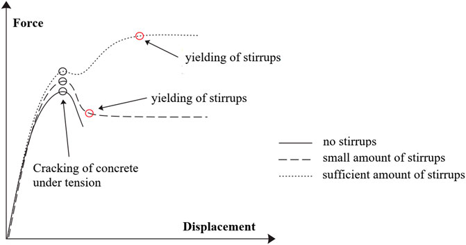
FIGURE 2. Force–displacement diagram of beam-column dowel connections with eccentrically placed dowel.
The diameter and spacing of the stirrups determine the influence of the reinforcement on the strength of the connection. If the precast elements are reinforced by a relatively large number of stirrups, the strength is typically higher than the concrete tensile strength. Consequently, the strength of the connection increases after crack formation (Figure 2). However, if the number of stirrups is low, the tensile strength of the concrete can, of course, be higher than the strength of the transverse reinforcement. In such situations, the strength of the connection would be reduced after the concrete has cracked (Figure 2).
In order to estimate the capacity of dowel connections against global failure, it has been assumed that the strength capacity is mainly provided by transverse reinforcement—the contribution of the concrete is not taken into account. The strength described in this way, as already discussed, may be greater or smaller than the strength given by the concrete's tensile strength.
Considering the crucial role of stirrups, a different approach was implemented from the studies described in Common Design Practice and Incomplete Mechanical Models Section. As shown in Figure 3, the stirrups were considered explicitly, employing a strut and tie model.
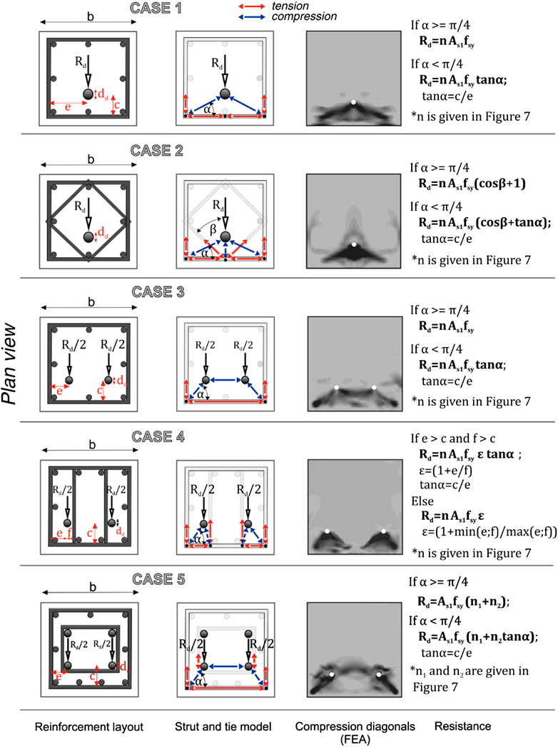
FIGURE 3. Calculation of the strength capacity of eccentric dowel connection, adopted from Zoubek et al. (2015).
Strut and tie models are already well established. In various codes (ACI 318-08; NZS 3101), they have been widely used, primarily to solve certain problems where the Bernoulli theorem of linear distribution of strains cannot be applied. Strut and tie models typically allow designers to choose how the load is transferred, choosing a certain stirrup arrangement. This arrangement determines an equivalent truss, where the tensile stresses in the stirrups (ties) are in equilibrium with the compressive stresses in the concrete (struts). These stresses should be sustained by both the concrete and the reinforcement.
A FEM numerical model in ABAQUS (ABAQUS, 2011) was developed based on the results of experiments to investigate the stress distribution in dowel connections. It was presented in Zoubek et al. (2013). The equivalent trusses corresponding to different common dowel connection configurations were defined using this model (Figure 3).
Typical configurations of the dowel connections are presented in the first column of Figure 3. In the second column the corresponding strut and tie model is illustrated. The calculated stresses are shown in the third column. In the final column, a closed expression for the estimation of strength is given. This strength corresponds to the yielding of the first layer of reinforcement. The local ductile failure mechanism is connected to the complete utilization of the compression struts, which is not considered in Figure 3.
Let us now analyze the capacities of the connections in more detail on the simple example of a single dowel (Figure 3, CASE 1). The equivalent truss consists of stirrups and two compression diagonals (Figure 4). The compression diagonals are formed in between the activated vertical corner bars and the dowel (Figure 4). Considering the equilibrium in the dowel, the compression forces C can be expressed as:
where α is the angle between the compression diagonal and the legs of the stirrups which are perpendicular to the loading direction and F is the force applied to the dowel.
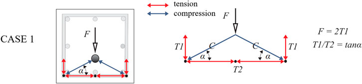
FIGURE 4. Strut and tie model for a connection with a single eccentric dowel and perimeter hoops [adopted from Zoubek et al. (2015)]
Considering the equilibrium in the corner nodes, the tensile forces which develop in the stirrups can be calculated as:
The force F can thus be expressed as:
If the dowel is positioned close to the edge of the concrete element (i.e. α < π/4), yielding will take place in the legs of the stirrups perpendicular to the loading direction. Thus, the strength capacity can be calculated as:
where As1 is the cross-section of a single leg of the perimeter hoop, and fsy is the steel yield strength of the steel.
If the distance between the edge and the dowel is greater (i.e. α > π/4) yielding will take place in the leg of the stirrups parallel to the direction of loading. The strength capacity can then be expressed as:
The critical region, where the spalling of the concrete is typically observed, is spread along the dowel. Consequently, more than one layer of stirrups may be engaged. The strength of the connection is influenced by all of these stirrups. Based on the experimental data and according to FEA (Zoubek et al., 2013), it has been concluded that the length/height of the critical region can be estimated as:
where c is the distance between the dowel axis and the stirrup axis and a is the vertical concrete cover of the outermost stirrup.
Taking into account the vertical distance s between the stirrups, the number of the activated stirrups n can be determined as:
Finally, the strength capacity of the dowel connection Rd is defined as the maximal force F applied to the dowel when yielding of the first layer of stirrups takes place. It is assumed that the stresses in the other stirrups decrease linearly. Considering the average stress in the stirrups σavg, the resistance of all stirrups can be calculated as:
if the dowel is positioned close to the edge of the section (α ≤ π/4), and
if the dowel is positioned far from the stirrups (α ≥ π/4).
In Eqs 10, 11, n is the number of activated stirrups, fsy is the yield strength of the steel, As1 is the cross-section of one stirrup's leg and α is the angle marked in Figure 4.
Typical Fastening Systems of Concrete Cladding Panels
Seismic Behaviour of Precast Buildings With Cladding Panels
During the earthquakes in Emilia–Romagna in Italy in 2012, RC precast buildings were amongst most vulnerable types of structures. The damage was observed on structural as well as on nonstructural components. Particularly vulnerable appeared to be the cladding panels and their connections with the main structural system (Figure 5). According to Bournas et al. (2013), for example, the collapse of cladding panels was observed in 75% of all precast buildings in the region. Liberatore et al. (2013) reported significant damage to claddings in 50% of 34 surveyed industrial buildings. Many authors (Ioannou et al., 2012; Belleri et al., 2014; Magliulo et al., 2014) emphasized that the cladding fastening systems were designed only for seismic forces perpendicular to the plane of the panel, which are proportional to the local mass of the panels, and for small out-of-plane horizontal loads (e.g. wind loads). At the time, the common opinion was that their poor resistance to the horizontal seismic loads in the plane of the panel was the leading cause of the failure of the fasteners.
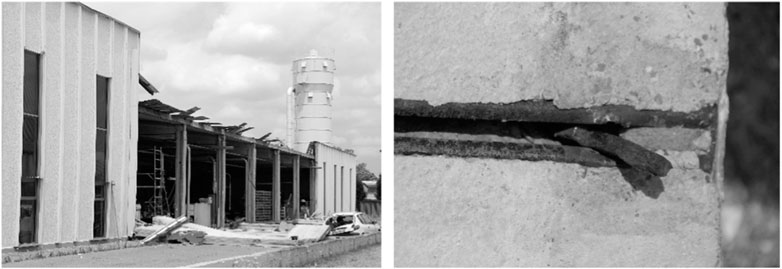
FIGURE 5. (left) Collapse of concrete cladding panels, and (right) failure of a typical cladding-to-structure connection during the Emilia earthquakes [adopted from Zoubek et al. (2016a)].
According to Belleri et al. (2015), Belleri et al. (2016), the high flexibility of RC precast industrial buildings led to displacement incompatibility between structural elements and concrete panels in the panel plane, which caused many failures of cladding fastening systems. The authors concluded that such systems should possess adequate ductility to accommodate the seismic displacement demand.
Taking into account the lessons learned from the L’Aquila and Emilia earthquakes, the cladding panel connections typically used in RC precast buildings in Europe have been analyzed analytically and experimentally within European project SAFECLADDING (2015). Vertical, as well as horizontal panels, were addressed. The investigated connections were mostly designed to be used in the non-seismic regions. Even though a little was known about their seismic response, they were extensively used in the seismic areas.
Based on the extensive experimental research, which is briefly summarized in Experiments Section and thoroughly presented in Zoubek et al. (2016a), the basic mechanisms of the seismic response of typical panels' connections between beams and vertical panels were identified. Considering the observed response, the appropriate numerical models, which can be used in the design practice, were developed and the design procedure, proposed. The estimation formulae for in-plane strength and displacement capacity are given in Shear Strength and Displacement capacity Section. Just recently results of research on typical connections between horizontal cladding panels and columns, also performed at the University of Ljubljana, were published in Starešinič et al. (2020). However, these findings are not included in this paper.
Experiments
The study carried out at the University of Ljubljana as part of the SAFECLADDING project initially focused on the connections that are most commonly used to attach vertical panels to precast beams. Such connections consist of a special steel strap (a hammer-head strap), a bolt, a washer, and two steel channels, which are attached to the reinforcement bars before the elements are cast. One of the channels is cast into the panel, while the other is cast into the structural element. The strap is fastened to the channel in the structural element by means of a bolt and a washer (Figure 6). The head of the strap is finally fixed inside the steel channel in the panel. In this way, a connection is created between the structural element and the panel.
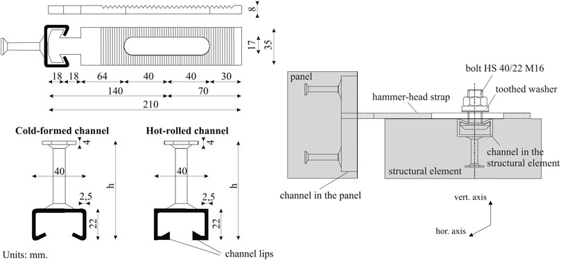
FIGURE 6. Geometry (left) of the tested connection and (right) of the connection assembly, adopted from Zoubek et al. (2016a).
Within the scope of the study presented in Zoubek et al. (2016a), 16 cyclic tests were performed on hammer-head strap connections. In Supplementary Table S1 the complete experimental programme is given. In general, the behaviour of the connections in both in-plane directions was analyzed. Thus the following three different types of tests were performed:
Uniaxial sliding tests: The load was applied in the direction of the vertical channel. Four such uniaxial tests were performed (Figure 6).
Uniaxial shear tests: The load was applied in the direction of the horizontal channel. The hammer-head strap connection was loaded in shear. A total of eight such tests were carried out (4 with cold-formed and 4 with hot-rolled channels).
Biaxial shear tests: To estimate the effect of out-of-plane force on the in-plane behaviour of the investigated connections, a constant out-of-plane force was simultaneously applied to the panel. Four such tests were carried out.
Figure 7 shows the observed response of the investigated connections with cold-formed channels subjected to a shear loading. At low actuator forces (0.5–1 kN), the strap rotates around the bolt, as shown in Figure 7 (see Stage 2). At some point (relative displacement of approx. 2–3 cm) the head of the strap becomes stuck inside the channel. Thus, the stiffness of the connection increases abruptly (Stage 2 in Figure 7). Yielding occurs in the narrow part of the strap at a shear load of approx. 3 kN. Lastly, the strap fails due to flexural failure in the narrow part (Stage 3 in Figure 7).
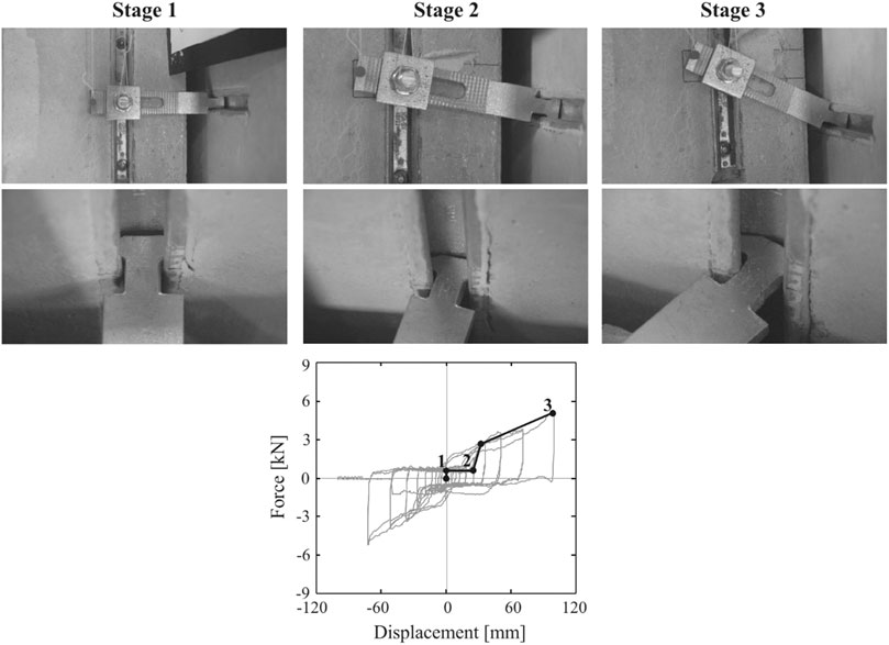
FIGURE 7. Failure mechanism of the investigated connections, adopted from Zoubek et al. (2016a).
If cold-formed channels were used instead of hot-rolled ones, failure did not occur in the strap, but in the channel. However, the recorded hysteretic loops look very similar.
In some tests, the gap between the panel and the beam closed before the failure of the strap or of the channel. In these cases, the recorded hysteretic behavior of the connection was considerably different. The gap closed at large displacements. Consequently, the friction between the panel and the beam led to an increase in stiffness. However, the strength capacity of the connection itself was not affected because the weakest link was still either the channel or the hammer-head strap, which failed at the same shear force as when the gap was not closed. The gap should therefore be large enough to allow the displacement capacity of connections to be utilized.
Biaxial tests with a constant perpendicular force P┴ were also conducted to determine the effect of an out-of-plane force on the resistance of investigated connections. Even though the mechanism of failure remained the same, the hysteresis clearly show, that in the case of biaxial loading, a higher stiffness can be observed. In these tests, the strap was stuck within the channel already in its initial position. Consequently, there was no sliding of the strap and the stiffness was greater. Surprisingly, the maximal obtained shear force at the failure of the biaxially loaded connections was higher than that recorded in the uniaxial tests.
Shear Strength and Displacement Capacity
An analytical model of the tested connections was developed based on the experimental results. Formulae have been proposed to define the force-displacement envelopes. In this paper, the expressions are presented in their final form and for cold-formed channels only. The derivation of these expressions including the formulae for the hot-rolled channels are given in Zoubek et al. (2016a).
Based on the equilibrium shown in Figure 8, the shear strength can be expressed by the following equation:
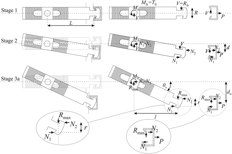
FIGURE 8. The shear force transfer mechanism in the investigated connections, and the state of equilibrium just before failure, adopted from Zoubek et al. (2016a).
In Eq. 12, T0 is the tightening torque, which was estimated to be equal to Mfr (Figure 8), R and L are the distances denoted in Figure 8 (Stage 1), du is the ultimate displacement, Rch is the out-of-plane resistance of the channel, which can be obtained from the product specification, and P┴ is the out-of-plane force. Equation 12 clearly explains how the shear resistance increases with increasing out-of-plane force (see also Experiments Section). It should be noted, however, that if the force acts in the opposite direction, the resistance is reduced.
The ultimate displacement du can be calculated as a sum of the displacement at which the strap gets stuck within the channel dgap and the displacement dch due to the deformation of the channel:
where θgap and θch are the corresponding rotations of the strap. While the rotation θgap can be estimated on the basis of the geometry of the strap and the channel, θch is relatively difficult to evaluate. When the experimental results were compared to the calculated values, the measured deformations of the channel were taken into account.
Seismic Fragility Analysis of Pre-code RC Precast Buildings With the Consideration of Nonstructural Elements
Description of the Analyzed Buildings
A large part of existing RC precast buildings was designed and constructed before the implementation of seismic codes. Apart from the deficiencies that are common to all types of pre-code RC buildings, such as the low amount of shear reinforcement, pre-code precast buildings also exhibit other weaknesses. Probably the most critical weakness of pre-code precast buildings is the inadequate design and construction of beam-to-column connections, which in many cases rely only on friction between the column and the beam. Another weakness of such buildings is the lack of a rigid diaphragm, which limits the ability of the structure to transfer lateral loads imposed by the perimeter nonstructural elements to the internal columns.
In this Section, seismic fragility analysis is summarized for four classes of pre-code single-storey precast buildings (i.e. B, V, H and M, Supplementary Table S2), which are described in more detail elsewhere (Babič and Dolšek, 2016). The building classes are defined by the statistical distribution of characteristics of the load-bearing structure and nonstructural elements. Characteristics of the load-bearing structure are the same for all building classes, while those of the nonstructural elements vary between the classes. Buildings in class B are without nonstructural elements (bare frame buildings), while buildings in classes V, H and M contain vertical precast panels, horizontal precast panels and masonry infills, respectively (Supplementary Table S2).
The load-bearing structures were defined based on previous studies (DOCUP, 2006; Casotto et al., 2015). These studies refer to precast buildings in Northern Italy, which, however, are similar to Slovenian precast buildings (e.g. Isaković et al., 2012). The structures consist of cantilever columns, which support long saddle beams covered by roof elements (Figure 9). The beam-to-column connections contain no mechanical elements and rely only on friction. The basic geometric and material parameters are presented in Figure 9. The cross-sectional dimensions (equal to 50 cm) and longitudinal reinforcement ratios (with the mean and the standard deviation equal to 1.13% and 0.22, respectively) of the columns were determined based on the building code that was in force at the time of the design (Casotto et al., 2015) and was associated with a design lateral load equal to two per cent of the buildings’ self-weight. A low transverse reinforcement ratio was assumed in all parts of columns, resulting in a confinement coefficient equal to 1.00.
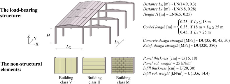
FIGURE 9. The configuration and basic characteristics of the load-bearing structures (top) and nonstructural elements (bottom). Some parameters are considered constant, while others are uncertain. The uncertain parameters follow either the lognormal (LN), uniform (U) or discrete uniform (DU) distribution.
The seismic response of the nonstructural elements (Figure 9) is mostly dependent on their connections with the structure. Vertical panels are attached to the beams at the top and restrained by a foundation beam at the bottom. The top connection contains the same type of fastenings, as described in Typical Fastening Systems of Concrete Cladding Panels Section. On the other hand, horizontal panels are attached to the columns. The connections at the top of the panels contain a steel box element, which is presented in more detail by Starešinič et al. (2020). However, at the bottom, horizontal panels are supported by small corbels that are installed into the columns. Furthermore, masonry infills are placed between the columns. Their connection to the adjacent structural elements relies only on friction, making the infills susceptible to overturning. The uncertain characteristics of nonstructural elements are assumed uniformly distributed. Their minimum and maximum values are reported in Babič and Dolšek (2016). However, the basic geometric and material parameters are also presented in Figure 9, while the modeling parameters are given later in Figure 10.
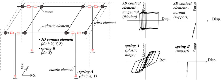
FIGURE 10. The model of the load-bearing structure (left) and the force-displacement (moment-rotation) relationship of the non-linear elements employed in the model (right).
Numerical Models of the Analyzed Buildings for Nonlinear Dynamic Analysis
For fragility analysis, a lumped plasticity model of precast buildings was developed using OpenSees software (McKenna and Fenves, 2010). The models were developed to be used in non-linear dynamic analyses considering all three ground motion components. In the case of the load-bearing structures, the same modeling principles were applied for all building classes. The models for building classes V, H and M, however, were expanded to also include the nonstructural elements. A summary of the models is provided in Load-Bearing Structure, Vertical and Horizontal Panels and Masonry Infills Sections, while their more detailed description can be found in Babič and Dolšek (2016).
Load-Bearing Structure
The columns were modeled by one-component lumped plasticity elements. At the base of each column, two independent rotational springs were assigned (about both principal directions) (spring A, Figure 10). The moment-rotation relationship of the springs was defined according to a previous study (Dolšek, 2010). Moreover, the beams were modeled by elastic elements. At the ends of these elements, nodal masses were applied to represent the mass of the structure. The beam-to-column connections were modeled by 3D contact zero-length elements, which allowed to simulate the support in the vertical direction as well as frictional forces in the horizontal directions. The friction coefficient was determined according to Magliulo et al. (2011), while no cohesion was assigned. The impact between the beams and columns was modeled by an elastic no-tension spring with an initial gap (spring B, Figure 10). For the modeling of other elements at the roof level, truss elements with elastic behaviour were used.
Vertical and Horizontal Panels
The effect of vertical panels was modeled by simulating only the response of the fastenings, thus assuming that the deformations in the panels are negligible in comparison to the displacement in the fastenings (Supplementary Figure S2, top left). Fastenings were modeled by several springs. Each spring connected the beams to the nodes that were fixed in the in-plane direction but unrestrained in the out-of-plane direction. The response in the in-plane direction (spring C, Supplementary Figure S2) was modeled by three springs in parallel which were calibrated on the basis of cyclic tests (Isaković et al., 2013). This included a perfectly elastic-plastic spring and two elastic-plastic springs with an initial gap. However, in the out-of-plane direction, the response of the fastenings was modeled by an elastic spring (spring E, Supplementary Figure S2). Half of the panels’ mass was considered in the out-of-plane direction, assuming that the other half is transferred directly to the foundation.
The horizontal panels were modeled by stiff elastic elements (Supplementary Figure S2, top right). In order to model the response of the bottom panel-to-column connections in the in-plane direction, two elements in parallel were used. The first element (i.e. a 3D contact element) was used to model the vertical support and friction, while the second element (i.e. a multilinear spring; spring F in Supplementary Figure S2) enabled to simulate the impact between the panel and the column, which occurs due to the limited length of the installation gap. In the out-of-plane direction, a stiff elastic spring was employed to prevent significant displacements between the panels and the columns. However, at the top of each panel, several springs were used to model the response of the fastenings. In the in-plane direction, a combination of five springs in parallel was used consisting of a perfectly elastic-plastic spring, and four elastic-plastic springs with an initial gap (spring D, Supplementary Figure S2), while in the out-of-plane direction, fastenings were modeled by an elastic spring (spring E, Supplementary Figure S2). The mass of each panel was lumped at its centre.
The potential failure of the fastenings installed in the vertical and horizontal panels (either in the in-plane or out-of-plane direction) was also modeled. The failure criteria were defined by the ultimate displacements (Supplementary Figure S2), which are described in more detail in Babič and Dolšek (2016). If any of the failure criteria for a given fastening was met, the panel that was attached by that fastening was removed from the model, so that its impact on the seismic response of the building was disregarded during the remaining part of the analysis.
Masonry Infills
A combination of stiff elastic elements and rigid constraints was used to model the masonry infills (Supplementary Figure S3). The masses of the infills were lumped at their centres. In the out-of-plane direction, the rocking of the infills was enabled by making use of elastic-no tension springs (spring G, Supplementary Figure S3). Moreover, the connections between the infills and the columns at the top were modeled by 3D impact zero-length elements. These elements enabled to simulate the friction in the out-of-plane direction as well as the in-plane non-linear response of the infills. The friction was modeled as in the case of the 3D contact zero-length elements (Figure 10), while the in-plane response of the infills was modeled by a bi-linear spring defined according to Panagiotakos and Fardis (1996). The potential failure of the infills was also considered. The failure criteria included the in-plane failure (associated with the exceedance of the infills’ in-plane strength) and out-of-plane failure (corresponding to the out-of-plane rotation exceeding the overturning rotation). If any of the failure criteria were met, the infill was immediately removed from the model.
Methodology for Fragility Analysis of the Investigated Building Classes
The methodology for fragility analysis was developed by Babič and Dolšek (2016) as a part of the seismic stress test, which was developed within the EU-funded project STREST. It is based on the methodology proposed by Casotto et al. (2015), where the basis for the seismic fragility analysis is a building class sample. The sample of each building class consisted of 100 buildings. The load-bearing structures were determined through simulated design (Casotto et al., 2015) considering the variations in the geometric and material properties. The sample values were obtained with the Monte Carlo simulation, which was also used to generate a sample of the nonstructural elements. A numerical model was then defined for each building from the building class sample. The performance of the sampled buildings was analyzed for 70 ground motions adopted from Casotto et al. (2015).
In each simulation, two types of damage states, i.e. the nonstructural and the structural damage state were determined. The nonstructural damage was defined by one of the four damage states, which corresponded to different portions of the dislocated nonstructural elements:
DS-0—no nonstructural element was dislocated.
DS-1—at least one nonstructural element was dislocated.
DS-2—at least half of the nonstructural elements were dislocated.
DS-3—all nonstructural elements were dislocated.
However, the structural damage was defined by one of the three damage states:
DS-NS—the structure suffered no or slight damage.
DS-M—the structure suffered moderate damage, which occurred if 1) the yield rotation was exceeded in at least one column, or 2) the sliding was initiated in at least one beam-to-column connection.
DS-C—the structure collapsed, which occurred if 1) the rotation in at least one column exceeded the ultimate rotation (EN 1998-3:2005), or 2) the relative beam drift in at least one beam-to-column connection exceeded the sliding capacity (i.e. the distance from the edge of the beam to the edge of the corbel).
Dependency between the nonstructural and the structural damage was accounted for by considering that all the nonstructural elements were dislocated in the case of structural collapse.
Based on data obtained with the simulations of seismic performance, the percentages of sample buildings meeting the designated damage states were determined for each ground motion separately. The regression analysis was then carried out to obtain the parameters of the fragility curves, i.e. the median seismic intensities corresponding to the onset of the damage states and the associated logarithmic standard deviations. As the intensity measure, the geometric mean of the peak ground acceleration in horizontal directions was used. In the regression analysis, lognormal distribution was assumed for the fragility curves, and their parameters were estimated by the maximum likelihood method (Baker, 2015). In Figure 11A, simulation data and the corresponding fragility curves are shown for two damage states, and building class V. An illustration of all fragility curves for this building class is presented in Figure 11B.
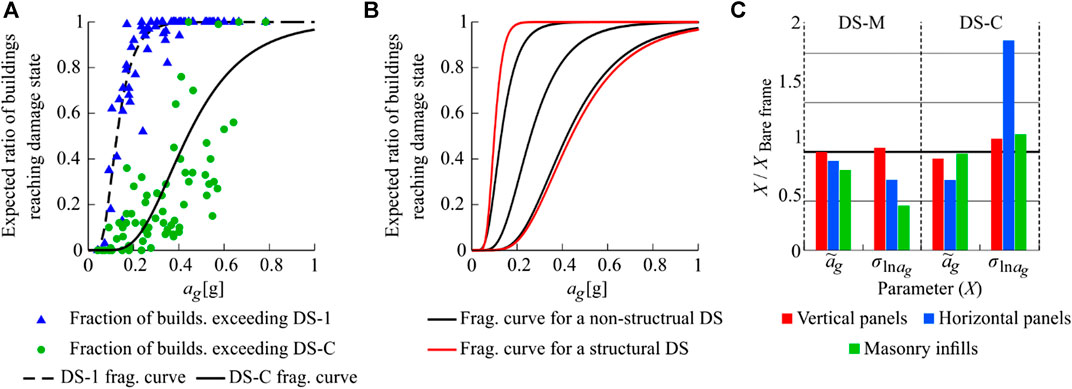
FIGURE 11. (A) Ratios of buildings from building class H exceeding DS-1 and DS-C with the corresponding fragility curves, (B) all fragility curves of building class V, and (C) fragility parameters (median and logarithmic standard deviation) of buildings classes V, H and M normalized to the fragility parameters of building class B.
Results and Discussion
Fragility curves for nonstructural damage states depended on the type of nonstructural elements (Supplementary Table S3). This was most significant in the case of damage state DS-1, where
The type of nonstructural elements also impacted fragility curves for the structural damage states (Supplementary Table S3; Figure 11C). While the vertical panels had no significant impact on moderate damage, the addition of the horizontal panels and masonry infills reduced both
The impact of nonstructural elements on the structural fragility can be explained by the simulated seismic response of buildings. From these simulations, it was observed that the largest rotations in the plastic hinges of the columns occurred in perimeter columns in buildings with horizontal panels. The large rotations in this type of buildings can be attributed to the inertial forces induced by the panels’ mass. In general, a part of these inertial forces is transmitted directly to the foundations of the perimeter columns, while the remaining part is transmitted to other columns through the roof elements. However, the part of the forces transmitted to the other columns can be only as large as the strength of the beam-to-column connections. Because the beam-to-column connections in the analyzed buildings rely solely on friction, their strength is relatively low. Therefore, a large part of the inertial forces induced by the panels was transmitted directly to the foundation, which meant that these inertial forces acted more locally than in the case of precast structures with strong beam-to-column connections. This resulted not only in the concentration of rotations in the perimeter columns but also in the increase of displacements in the perimeter beam-to-column connections. Moreover, it was observed that masonry infills increased the stiffness in the in-plane direction and thus reduced the rotations at the bases of the columns. However, this increased the demand in the beam-to-column connections at the perimeter. Consequently, relative displacements in the beam-to-column connections of the precast buildings with masonry infills were larger than those observed in the bare frame buildings. Lastly, the vertical panels impacted the seismic response mostly with their mass. In this case, the panels-induced inertial forces acted on the structure above the beam-to-column connection, which increased the displacements in the connections, but had a small effect on the rotations in the columns.
The results of the fragility analysis were used in the seismic risk evaluation of pre-code RC precast buildings in Tuscany, Italy (Pitilakis et al., 2018). It was found that the seismic risk was too high, which signals the importance of strengthening interventions for this type of buildings. The results, discussed above, showed that the strengthening interventions should be focused on improving the seismic behaviour of the connections between the precast elements. This includes strengthening of the beam-to-column connections and increasing the in-plane stiffness of the connections between the roof elements. However, it also encompasses the strengthening of the connections between the structural and nonstructural elements and/or reducing the damaging consequences of the failure of such connections. For this reason, special seismic restrainers were developed at the University of Ljubljana, which help to prevent the cladding panels from causing damage after their dislocation from the structure. The seismic restrainers are presented in Strengthening Interventions for Existing Precast Buildings with Cladding Panels Section.
Strengthening Interventions for Existing Precast Buildings With Cladding Panels
Seismic Restrainers
Based on the field reconnaissance reports and relevant research (see also Typical Fastening Systems of Concrete Cladding Panels and Seismic Fragility Analysis of Pre-Code RC Precast Buildings with the Consideration of Nonstructural Elements Sections) it can be assumed that improvements to RC precast structures with concrete cladding panels and the design of new connection types are needed. Withing the framework of the SAFECLADDING project (2015) several advanced solutions have been developed. However, the research was not limited to new types of fastening systems, but also concentrated on the protection of the existing RC precast structures. For instance, an economically appealing and simple strengthening device (seismic restrainer) has been developed at the University of Ljubljana (Figure 12), which was first described in Zoubek et al. (2016b). Its use is not limited only to existing precast buildings. It could also be used to prevent the falling of panels in new structures.
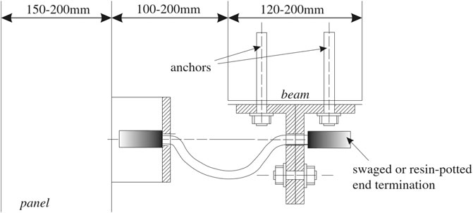
FIGURE 12. A scheme of a restrainer system as a strengthening solution for the protection of cladding panels upon the failure of the primary cladding-to-structure connections [adapted from Zoubek et al. (2016b)].
The concept of restrainers in seismic engineering is not an entirely new one. In the 1971 San Fernando earthquake in California, several simply supported multi-span bridges collapsed due to the excessive displacements which took place at supports and expansion joints (Randall et al., 1999). In order to limit the risk of superstructure unseating, the California Department of Transportation (CALTRANS) has since installed seismic restrainers in bridges (Randall et al., 1999). In Northern America commonly used restrainers connect girders to the bent cap. In 1999 Randall et al. published an extensive study on design procedures for such restrainer systems. The available literature contains many other related works by different authors (e.g. Saiidi et al., 2001; DesRoches et al., 2003; Hayashikawa et al., 2006). In these studies, a large part of effort was dedicated to the development of design rules. Unfortunately, the outcomes of these studies do not directly apply to RC precast buildings, where the restrainers would be activated upon the failure of the primary cladding-to structures fastening system, when considerable relative displacement between the structure and the panel is developed. Seismic restrainers in bridges are activated already at small longitudinal movements of the superstructure to prevent its unseating. In short, initial and boundary conditions are significantly different. New design procedures for the estimation of forces in restrainers in precast structures are therefore needed. These are summarized in the following sections.
Development of Restrainers for Cladding in Precast Structures
To protect the concrete cladding panels in case of a an earthquake, a back-up fastening system is proposed. The system is based on the use of a synthetic fiber rope or steel restrainer (Figure 12). Due to the limited distance between the panels and the bare frame in RC precast buildings, the rope would be normally rather short (less than 70 cm). The distance between the main structural systems and the concrete panels in precast buildings is normally limited. Therofore the length of the ropes/restrainers would be relatively short (up to 100 cm). They are designed to be long enough to be triggered only in the case of failure of the primary cladding-to-structure connections occur and should not attach the panels to the structure. Therefore, they should have no influence on the response of a structure and panels as long as the primary cladding-to-structure connections are in operation.
As described in Zoubek et al. (2016b), the ropes/restrainers are connected to angular and omega steel profiles which are fastened to the panels and structural elements. The ropes are anchored in the profiles by means of resin-potted or swaged terminations. The gap between the panels and RC precast beams with realistic dimensions of the elements is illustrated in Figure 12. It is important that all system components presented here should be designed to withstand the expected seismic loads. At the University of Ljubljana, tensile tests on steel wire ropes with different swaged end terminations and synthetic fiber ropes with resin-potted terminations were performed (Isaković et al., 2015). In Supplementary Table S4, all tested combinations are given. Three 8–12 mm steel wire ropes and four different 8 mm synthetic fiber ropes were loaded in tension until failure. Supplementary Figure S4 shows the recorded stiffness and strength. Failure of the restrainer occurred, in most of the tests, due to the insufficient strength of the rope termination.
The tests described above were performed on the restrainers attached to the T and omega profiles (as shown in Figure 12), which were fixed to the actuators. The anchors used for fixing the profiles to concrete elements were not investigated. Their performance was examined in the Slovenian national project Seismic Resilience and Strengthening of Precast Industrial Buildings with Concrete Claddings. However, the results of this research are not presented in this paper. Withing the framework of the above-mentioned project, also full-scale shaking table tests on a RC precast structure with concrete cladding panels were performed.
Seismic Demand on a Restrainer
Restrainers used to prevent the falling of concrete cladding panels are triggered for time periods of about 0.1 s [for a detailed analysis see Zoubek et al. (2016b)]. The dynamic behaviour of the panels and the primary structure at the time of their activation is relatively complicated. In this paper some equations derived in Zoubek et al. (2016b) are given which can be used to estimate the maximum expected impact forces in a restrainer system. It is important to note that they can be applied only in the case of short restrainers (Figure 13, left). When long restrainers are used (Figure 13, right), higher maximum forces may occur due to the additional angular acceleration of the panel induced by gravity G. In this second cases, it would be therefore important to take into account the P-Δ effect. If the influence of the P-Δ effect can be neglected, the dynamic response of the system can be described with acceptable accuracy by employing a relatively simple analytical model defined in Figure 14.
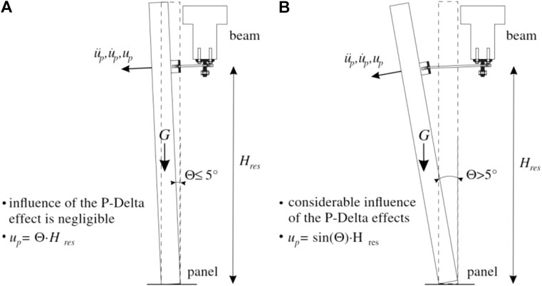
FIGURE 13. (A): Small inclination of the panel in the case of short restrainers—the P–Δ effect is negligible. (B): Significant inclination of the panel in the case of long restrainers—the P–Δ effect should be taken into account [adopted from Zoubek et al. (2016b)].
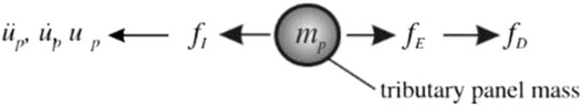
FIGURE 14. A mathematical model used to calculate the maximum forces in a restrainer system:
As demonstrated in Figure 14, the equilibrium of forces acting on the system can be written as
where fD is the damping force, fE is the force in the restrainers, and fI is the inertial force of the panel.
The inertial force fI can be calculated as the product of the panel mass per restrainer mp and the panel acceleration in the direction perpendicular to the panel plane üp [Figure 13 (left)]:
By applying Hooke's law the force in the restrainer fE can be simply calculated:
where kres is the restrainer stiffness and ur is the relative displacement equal to the deformation of the restrainer.
If the damping of the secondary system does not have any considerable effect on the tensile forces in the restrainers, one can assume fD = 0. The simplification is reasonable while a relatively small amount of mechanical energy can be converted through damping in a short period of time when the restrainers are triggered (Fajfar, 1984).
Considering Eqs 15, 16 and assuming fD = 0, Eq. 14 takes the following form:
Let us now express the relative acceleration ür as the difference between the absolute acceleration of the structure üs and the absolute acceleration of the panel üp:
Taking into account the relationship defined in (18), Eq. 17 can be rewritten as follows:
The solution of Eq. 19 can be written as:
Where
While the oscillation period of the main structure is probably approx. ten times longer than the impact duration (Zoubek et al., 2016b), it can be assumed that the acceleration of the main structure (beam) üs= as is invariant during the time when the restrainer is triggered. Therefore, f0 can also be considered constant. This assumption is confirmed in Zoubek et al. (2016b), based on the results of the performed non-linear time history analysis.
The constants A and B in Eq. 20 can be calculated by considering the initial conditions just before the impact:
The coeffcients A and B are thus equal to:
Taking into account Eqs 20, 24 the relative displacement ur can be expressed as:
The tensile force in the restrainer can be evaluated as:
Function given in Eq. 26 has a maximum:
where
The stiffness kres can be measured or obtained from the technical specification of the used product. The stiffness of the synthetic fiber ropes tested at the University of Ljubljana was approx. 2MN/m (Isaković et al., 2015). By taking into account the number of installed restrainers, the corresponding panel mass per restrainer mp can be estimated. In contrast to these two variables, the estimation of the acceleration of the main structure during the activation of the restrainer as and of the relative velocity between the structure and the panel at the beginning of the activation of the restrainer vr0 are obviously not trivial tasks. In Figure 15, where the results of the non-linear time history analysis and the estimations calculated with the proposed formula are compared, the velocity vr0 is taken from the results of the performed numerical analysis. The acceleration as is simply evaluated from the Eurocode 8 (EN 1998-1:2004) response spectrum.
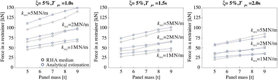
FIGURE 15. The match between the maximal forces in a restrainer obtained by using the proposed analytical expression and the results of the response history analysis (RHA).
The results from response history analysis, presented in Zoubek et al. (2016b), were compared with the results obtained with the proposed analytical expressions. The comparison was made for varying panel masses, natural periods of the main structural system and restrainer stiffnesses. Since there are two restrainers per panel, 1/4 of the whole panel mass was taken as a corresponding mass mp. The relative velocity vr0 was calculated as the product of the ratio
where Sa(Tps) is the spectral acceleration to the period Tps.
The acceleration of the main structure as, was also calculated as the spectral acceleration Sa(Tps) according to the EC8 (EN 1998-1:2004) design acceleration spectrum:
The match between the results obtained by using the proposed analytical formula (blue lines) and the numerically obtained results (black lines), as reported in Zoubek et al. (2016b), is illustrated in Figure 15. The graphs show relatively good agreement between the results, regardless of the period of vibration of the main structure Tps, restrainer stiffness kres or the panel mass.
Conclusion
In the last 2 decades, seismic response of RC precast buildings has been the subject of intense research, supported by European research programmes and precast producers. The University of Ljubljana contributed considerable experimental and analytical work. In this paper, only a few of the most important results and findings from the last few years are gathered and briefly presented. The main contributions include:
Development of the new capacity model of beam-column dowel connections, which are one of the key parts of RC precast structural system. Most importantly, the new model explicitly considers the contribution of stirrups in the critical region around the dowel, where precast elements are typically reinforced by quite compact transverse reinforcement.
The new insight into the cyclic behaviour of fastening systems of concrete cladding panels and new design procedures for the estimation of strength and displacement capacity of cladding fasteners. This knowledge represents a basis for the adequate design of the cladding fasteners, which can prevent the failure of concrete cladding panels and further prevent human casualties and enormous financial losses due to the terminated services.
Development of a methodology for seismic fragility analysis of RC precast buildings, and the fragility curves of precast RC building classes, which can be used for performing seismic stress test of portfolio of RC precast buildings and for the safety-calibration of the new design procedures of RC precast buildings.
Development of a relatively simple and economically attractive back-up (strengthening) system to prevent the falling of panels in case of a strong earthquake. The system is based on the use of a loose steel or synthetic fiber rope restrainer. In order to measure their resistance to shock loading, several tensile tests in varying configurations were performed. Furthermore, analytical formulae for the estimation of the seismic demand have been proposed.
Author Contributions
All authors listed have made a substantial, direct, and intellectual contribution to the work and approved it for publication. Sections Beam-to-Column Dowel Connections, Typical Fastening Systems of Concrete Cladding Panels and Strengthening Interventions for Existing Precast Buildings with Cladding Panels are the work of authors BZ, TI, and MF. Section Fragility Analysis of Pre-Code RC Precast Buildings with the Consideration of Nonstructural Elements is the work of authors AB and MD.
Funding
The presented research was mainly supported by the two large EU projects: (a) SAFECAST project "Performance of Innovative Mechanical Connections in Precast Building Structures under Seismic Conditions" (Grant Agreement No. 218417-2), and (b) SAFECLADDING project – "Improved Fastening systems of Cladding Wall Panels of Precast Buildings in Seismic Zones" (Grant Agreement No. 314122), both in the Seventh Framework Programme (FP7) of the European Commission. Both projects were led by the associations of the precast producers in Europe and the Politecnico di Milano. The leading persons in this research were in particular Professor Giandomenico Toniolo and Dr. Antonella Colombo. The presented results are also based on the work conducted within the Earthquake Engineering research program (evidence number P2-0185), which is supported by the Slovenian Research Agency.
Conflict of Interest
The authors declare that the research was conducted in the absence of any commercial or financial relationships that could be construed as a potential conflict of interest.
Supplementary Material
The Supplementary Material for this article can be found online at: https://www.frontiersin.org/articles/10.3389/fbuil.2021.630952/full#supplementary-material.
References
ACI 318-08. (2008). Building code requirements for structural concrete and commentary. Farmington Hills, Michigan, USA: American Concrete Institute.
Babič, A., and Dolšek, M. (2016). Seismic fragility functions of industrial precast building classes. Eng. Struct. 118, 357–370.
Baker, J. W. (2015). Efficient analytical fragility function fitting using dynamic structural analysis. Earthq. Spectra 31 (1), 579–599. doi:10.1193/021113eqs025m
Belleri, A., Brunesi, E., Nascimbene, R., Pagani, M., and Riva, P. (2014). Seismic performance of precast industrial facilities following major earthquakes in the Italian territory. J. Perform. Constr. Facil. 29 (5), 04014135.
Belleri, A., Torquati, M., Marini, A., and Riva, P. (2016). Horizontal cladding panels: in-plane seismic performance in precast concrete buildings. Bull. Earthq. Eng. 14 (4), 1103–1129. doi:10.1007/s10518-015-9861-8
Belleri, A., Torquati, M., Riva, P., and Nascimbene, R. (2015). Vulnerability assessment and retrofit solutions of precast industrial structures. Earthq. Struct. 8 (3), 801–820. doi:10.12989/eas.2015.8.3.801
Bournas, D. A., Negro, P., and Taucer, F. F. (2013). Performance of industrial buildings during the Emilia earthquakes in Northern Italy and recommendations for their strengthening. Bull. Earthq. Eng. 12 (5), 2383–2404. doi:10.1007/s10518-013-9466-z
Capozzi, V., Magliulo, G., and Manfredi, G. (2012). Nonlinear mechanical model of seismic behaviour of beam-column pin connections, in 15th world conference on earthquake engineering, Portugal, Lisbon, 24–28 Sept 2012.
Casotto, C., Silva, V., Crowley, H., Nascimbene, R., and Pinho, R. (2015). Seismic fragility of Italian RC precast industrial structures. Eng. Struct. 94, 122–136. doi:10.1016/j.engstruct.2015.02.034
CEN-TC250-SC8_N0966 (2020). prEN 1998 -1-2:2020 Eurocode 8: design of structures for earthquake resistance Part 1-2: rules for new buildings.
Cornell, C. A. (1996). “Calculating building seismic performance reliability: a basis for multi-level design norms”, in Proceedings of the 11th World conference on earthquake engineering (Acapulco).
DesRoches, R., Pfeifer, T., Leon, R. T., and Lam, T. (2003). Full-scale tests of seismic cable restrainer retrofits for simply supported bridges. J. Bridge Eng. 8 (4), 191–198. doi:10.1061/(asce)1084-0702(2003)8:4(191)
DOCUP. (2006). Programma DOCUP Toscana 2000–2006. Misura 2.8.3: Riduzione del rischio sismico nelle aree produttive. Regione Toscana, Direzione Generale Politiche Territoriali, Ambientali e per la Mobilità Coordinamento Regionale Prevenzione Sismica: Report. (In Italian).
Dolšek, M. (2010). Development of computing environment for the seismic performance assessment of reinforced concrete frames by using simplified nonlinear models. Bull. Earthq. Eng. 8 (6), 1309–1329. doi:10.1007/s10518-010-9184-8
EN 1998-1:2004. (2004). Eurocode 8: design of structures for earthquake resistance – Part 1: general rules, seismic Actions and rules for buildings. Brussels: European Committee for Standardization.
EN 1998-3:2005. (2005). Eurocode 8: design of structures for earthquake resistance—Part 3: assessment and retrofitting of buildings. Brussels: European Committee for Standardization.
Fajfar, P. (1984). Dynamics of structurescivil engineering and geodesy. Ljubljana, Slovenia: University of Edvard Kardelj in Ljubljana, Faculty of architecture.
Fischinger, M., Zoubek, B., and Isaković, T. (2014). “Seismic response of precast industrial buildings,” in Perspectives on European earthquake engineering and seismology. Editor A. Ansal (Cham: Springer), 131–177.
Fuchs, W., Eligehausen, R., and Breen, J. E. (1995). Concrete capacity design (CCD) approach for fastening to concrete. ACI Struct. J. 92 (1), 73–94.
Hayashikawa, T., Julian, D. R., and Galindo, C. M. (2006). “Critical performance of unseating prevention cable restrainers under level II earthquakes”, in Proceedings of the Annual conference of Japan society for civil engineers (Kyoto).
Ioannou, I., Borg, R., Novelli, V., Melo, J., Alexander, D., Kongar, I., et al. (2012). The 29th May 2012 Emilia Romagna Earthquake. EPICentre field observation report No. EPI-FO-290512. College London, United Kingdom: Department of Civil, Environmental and Geomatic Engineering, University.
Isaković, T., Fischinger, M., Karadogan, F., Kremmyda, G. D., Dal Lago, B., Pegan, A., et al. (2012). Catalogue on the existing cladding panel systems and connections in precast buildings with the identification of their possible seismic deficiencies, SAFECLADDING, Deliverable 1.1. Brussels: European Commission.
Isaković, T., Zoubek, B., and Fischinger, M. (2015). “Report and card files on the tests performed on existing connections – update”, in SAFECLADDING, Deliverable, 1.3. Ljubljana, Slovenia: University of Ljubljana.
Isaković, T., Zoubek, B., Lopatič, J., Urbas, M., and Fischinger, M. (2013). “Report and card files on the tests performed on existing connections”. in SAFECLADDING, Deliverable, 1.2. Ljubljana, Slovenia: University of Ljubljana.
Liberatore, L., Sorrentino, L., Liberatore, D., and Decanini, L. D. (2013). Failure of industrial structures induced by the Emilia (Italy) 2012 earthquakes. Eng. Fail. Anal. 34, 629–647. doi:10.1016/j.engfailanal.2013.02.009
Magliulo, G., Capozzi, V., Fabbrocino, G., and Manfredi, G. (2011). Neoprene-concrete friction relationships for seismic assessment of existing precast buildings. Eng. Struct. 33 (2), 532–538. doi:10.1016/j.engstruct.2010.11.011
Magliulo, G., Ercolino, M., Petrone, C., Coppola, O., and Manfredi, G. (2014). The Emilia earthquake: seismic performance of precast reinforced concrete buildings. Earthq. Spectra 30 (2), 891–912. doi:10.1193/091012eqs285m
McKenna, F., and Fenves, G. L. (2010). Open system for earthquake engineering simulation (OpenSees). Berkeley, USA: Pacific Earthquake Engineering Research Center. http://opensees.berkeley.edu. Accessed November 10, 2020).
NZS 3101. (2006). Concrete structures standard. Part 1 – The design of concrete structures and Part 2 – commentary. Wellington, New Zealand: Standards New Zealand.
Panagiotakos, T. B., and Fardis, M. N. (1996). “Seismic response of infilled RC frame structures”, in Proceedings of the 11th World conference on earthquake engineering (Acapulco).
Pitilakis, K., Argyroudis, S., Fotopoulou, S., Karafagka, S., Kakderi, K., Selva, J., et al. (2018). “A multi-level stress test methodology: application to six critical infrastructures in Europe”, in Proceedings of the 16th European conference on earthquake engineering (Thessaloniki).
Psycharis, I. N., and Mouzakis, H. P. (2012). Shear resistance of pinned connections of precast members to monotonic and cyclic loading. Eng. Struct. 41, 413–427. doi:10.1016/j.engstruct.2012.03.051
Randall, M., Saiidi, M., Maragakis, E., and Isaković, T. (1999). Restrainer design procedures for multi-span simply-supported bridges. Technical report MCEER-99-001. Reno: Civil Engineering Department, University of Nevada.
SAFECLADDING. (2015). Safecladding Project – improved fastening systems of cladding wall panels of precast buildings in seismic zones. www.safecladding.eu. Accessed January 15, 2016.
Saiidi, M., Randall, M., Maragakis, E., and Isakovic, T. (2001). Seismic restrainer design methods for simply supported bridges. J. Bridge Eng. 6, 307–315. doi:10.1061/(asce)1084-0702(2001)6:5(307)
Starešinič, G., Zoubek, B., Gams, M., Isaković, T., and Fischinger, M. (2020). Modelling in-plane dynamic response of a fastening system for horizontal concrete facade panels in RC precast buildings. Eng. Struct. 224, 111210.
Tanaka, Y., and Murakoshi, J. (2011). Reexamination of dowel behavior of steel bars embedded in concrete. ACI Struct. J. 108 (6), 659–668.
Vintzeleou, E. N., and Tassios, T. P. (1986). Mathematical model for dowel action under monotonic and cyclic conditions. Mag. Concr. Res. 38 (134), 13–22.
Zoubek, B., Fischinger, M., and Isaković, T. (2016a). Cyclic response of hammer-head strap cladding-to-structure connections used in RC precast building. Eng. Struct. 119, 135–148. doi:10.1016/j.engstruct.2016.04.002
Zoubek, B., Fischinger, M., and Isakovic, T. (2015). Estimation of the cyclic capacity of beam-to-column dowel connections in precast industrial buildings. Bull. Earthq. Eng. 13 (7), 2145–2168. doi:10.1007/s10518-014-9711-0
Zoubek, B., Fischinger, M., and Isakovic, T. (2016b). Seismic response of short restrainers used to protect cladding panels in RC precast buildings. J. Vib. Control. 24 (4), 645–658. doi:10.1177/1077546316659780
Keywords: precast buildings, dowel beam-to-column connections, precast cladding panels, frictional beam-to-column connections, masonry infills, seismic fragility analysis, seismic restrainers
Citation: Zoubek B, Babič A, Dolšek M, Fischinger M and Isaković T (2021) Recent Advances in the Research of the Seismic Response of RC Precast Buildings at the University of Ljubljana. Front. Built Environ. 7:630952. doi: 10.3389/fbuil.2021.630952
Received: 18 November 2020; Accepted: 27 January 2021;
Published: 26 March 2021.
Edited by:
Bruno Dal Lago, University of Insubria, ItalyReviewed by:
Roberto Nascimbene, Fondazione Eucentre, ItalyGennaro Magliulo, University of Naples Federico II, Italy
Copyright © 2021 Zoubek, Babič, Dolšek, Fischinger and Isaković. This is an open-access article distributed under the terms of the Creative Commons Attribution License (CC BY). The use, distribution or reproduction in other forums is permitted, provided the original author(s) and the copyright owner(s) are credited and that the original publication in this journal is cited, in accordance with accepted academic practice. No use, distribution or reproduction is permitted which does not comply with these terms.
*Correspondence: Blaž Zoubek, Ymxhei56b3ViZWtAc2NoaW1ldHRhLmF0
†Present Address: Blaz Zoubek, Schimetta Consult ZT GmbH, Salzburg, Austria.