 Fabio Minghini
 Nerio Tullini
- 1Engineering Department, University of Ferrara, Ferrara, Italy
In 2012, the North of Italy was hit by a seismic sequence characterized by two main events occurred on May 20 and 29 with MW = 6.1 and 6.0, respectively. Those earthquakes were particularly severe toward precast Reinforced Concrete (RC) structures not designed for seismic resistance. In the past years, the authors implemented a database collecting damage data and typological information on the industrial buildings struck by the Emilia earthquakes. That database was used to develop empirical fragility curves, which highlighted the considerable vulnerability of precast buildings conceived in accordance with pre-seismic code provisions. More recently, the interventions of seismic retrofitting on the same buildings, funded by the Emilia-Romagna region and designed by engineers which were directly hired by the companies, were examined in detail and critically revisited. A selection of these interventions is presented in this paper, which analyzes the effectiveness of the various retrofitting solutions, with a specific attention to the force transfer mechanisms between existing structures and strengthening systems. The interventions are divided between column strengthening (based, for example, on RC or steel jacketing) and interventions aimed at providing the building with a suitable earthquake resistant system (based, for example, on either the use of the existing cladding panels or the implementation of new bracing systems). Graphical representations of the analyzed solutions with the relevant construction details are provided.
Introduction
The region hit by the 2012 Emilia earthquakes is one of the most productive areas in Italy. It is enough to think of the number of industrial buildings located in the Emilia-Romagna region, which is almost 80,000, corresponding to about 12% of the industrial buildings in the whole Italy.
The majority of these buildings are single-storey precast Reinforced Concrete (RC) structures, with columns clamped at the base, main girders simply supported at the column tops and secondary beams or slab elements spanning in the direction orthogonal to the main girders and simply supported on them (Colombo et al., 2012). Some buildings might have an intermediate floor portion hosting offices, usually located in eccentric position along one of the two short edges. In some case, a precast vaulted roof may be present (Poiani et al., 2020).
The struck region was not covered by seismic design provisions until October 2005. As a consequence, most of the industrial buildings in the region featured friction-based connections between the various precast members and were lacking of any structural redundancy. This led to a huge number of brittle failure mechanisms associated with the loss-of-support of beams and slabs, and with the out-of-plane collapse of cladding panels. In addition, heavy damages to columns were observed in several cases, such as the formation of a plastic hinge at the base.
Several researches have analyzed the causes of damages and collapses that affected the industrial buildings in Emilia (Liberatore et al., 2013; Bournas et al., 2014; Magliulo et al., 2014; Belleri et al., 2015a; Ercolino et al., 2016; Minghini et al., 2016; Savoia et al., 2017). All studies agrees that deficiencies of connections represent the main cause of collapses, followed by inadequacy of column reinforcement and foundations. Recent studies show that also the vertical component of the ground motion (Bovo and Savoia, 2019), particularly in the free field, and masses of overhead cranes and hoist loads (Belleri et al., 2017), which may be often present in industrial buildings, could have played a role in the landscape of damages.
Due to the above rembered critical issues, a growing interest for fragility assessments of pre-seismic industrial buildings from a regional perspective is observed in Italy (Casotto et al., 2015). With specific regard to the Emilia earthquakes, a damage database was implemented by Minghini et al. (2016) and used by Buratti et al. (2017) for the evaluation of empirical fragility functions. The information collected in that database includes geolocalization, structural typology, dimensions, construction details and damage state for more than 1,400 precast RC buildings. The damage data were derived from reports prepared by professional engineers appointed by building owners to survey the buildings, design retrofitting interventions and apply for regional funds. These reports were validated by a public in-house company in charge of assessing the coherence of public funding with the planned interventions. Depending of the damage state, the funding was available for either reconstruction or retrofitting (Emilia-Romagna Regional Decree No. 57, 2012), but also the interventions on undamaged buildings characterized by structural deficiencies were funded. From the fragility assessment performed by Buratti et al. (2017), pre-seismic precast buildings result to be much more vulnerable than cast-in-place framed buildings, so requiring the introduction of specific fragility models.
These results are confirmed by recent analyses based on the official database of the Emilia-Romagna region (Rossi et al., 2019; Rossi et al., 2020). The latter includes information concerning not only industrial buildings, but also precast structures used for business activities in trade or agriculture, and allowed for comprehensive loss analyses.
The predominance of damages related with connections deficiencies justifies the two-step intervention strategy which was planned for the struck territory since June 2012 (Legislative Decree No. 74, 2012).
In the first step, in order to ensure the temporary usability of the buildings, it was mandatory to provide connections with mechanical devices able to prevent the unseating of precast elements and collapse of cladding panels. Sometimes, friction-based connections were strengthened using post-inserted dowels. These connections may exhibit a pseudo-ductile behavior, provided that they are designed to develop dowel yielding and avoid concrete splitting failure. For a detailed analysis of the seismic response of precast buildings with dowel-type connections the reader is referred to recent studies by Clementi et al. (2016) and Mezzapelle et al. (2017).
In the second step, structural safety verifications of the buildings were to be carried out, followed, if necessary, by seismic retrofitting.
For some recent study on how to reproduce numerically the seismic response of precast buildings for safety verifications, the reader is, for example, referred to Fischinger et al. (2014). Some solutions for first- and second-step interventions were discussed by Belleri et al. (2015b). Proposals for soil and foundation strengthening were presented by Maugeri et al. (2013). The graphical data sheets for the retrofitting interventions proposed by Colombo et al. (2012) inspired several engineers in developing design solutions for precast buildings damaged by the Emilia earthquakes. However, those proposals, have not always been tailored to specific design situations and existing precast members’ dimensions. As a result, they may have been misinterpreted, sometimes resulting in a not full effectiveness of the retrofitting.
Aims and Objectives
The database implemented by Minghini et al. (2016) was recently enriched to include information on retrofitting solutions adopted for precast buildings in Emilia. This paper presents a graphical representation of some of these interventions, and presents for them a critical analysis. The main objective of this study is to investigate the stress transfer mechanisms which potentially arise between existing structures and strengthening systems. A further objective is to propose, for some case, an improved solution characterized by more effective stress transfers.
In order to cover a spectrum of design solutions as large as possible, the described retrofitting interventions make use of quite common materials, methods and technologies. Hence, advanced devices, such as, for example, those investigated by Pollini et al. (2018), although of great significance, are out of the scope of this study.
Finally, some consideration on the influence of roof stiffening is presented. For the building typologies covered by this study, the roof slabs do not possess, in general, an in-plane stiffness sufficient to behave as a rigid diaphragm. However, some retrofitting solution may involve roof stiffening for various reasons. For example, to make effective the introduction of bracing systems, the deformable roofs must be stiffened. This will imply a change in the force distributions which should be accounted for.
Critical Analysis of Retrofitting Interventions
For reading convenience the intervention proposals described are divided in column strengthening, interventions on cladding panels and implementation of new bracing systems.
Column Strengthening
In modern precast buildings, columns and their connections with the foundations are designed to exhibit stable cyclic behavior with good dissipating properties and capacity comparable with that of cast-in-place columns (Dal Lago et al., 2016; Tullini and Minghini, 2020). In existing buidings, these characteristics are not present.
The retrofitting solutions presented in this section derive from the need for column strenghtening due to either the presence of an insufficient longitudinal reinforcement inside the column or a flexural capacity degraded as a consequence of seismic damage. For example, the interventions described in Steel Jacketing section may serve to increase the column capacity up to acceptable values, whereas the intervention presented in RC Jacketing section could be applied even to an heavily damaged column with plastic hinge fully developed at its base. In this case, the contribution due to existing concrete and reinforcing steel is nullified, and the strengthening material should be designed to completely balance the bending moment and shear acting at the column base in the relevant design situations.
However, in the presence, at the end of a seismic event, of residual deformations, the columns may often result to be unrepairable. This is the case, for example, for columns experiencing either rigid base rotations due to foundation settlements or so significant flexural damage to remain inclined after the earthquake.
Despite the fact that Regional Decree No. 57 (2012) discriminates between unsalvageable and heavily damaged, but still repairable industrial buildings on the basis of, in addition to other damage parameters, the number of columns suffering a residual drift larger than 2% (see Table 1 reported by Minghini et al., 2016), it is worth observing that a smaller drift limit should be used to identify the damage level at the end of the seismic event. In fact, a 2% drift is more likely to represent the maximum deformation attained during the seismic event (FEMA 356, 2000) rather than the permanent deformation at the end of shaking. A proof of this feature is reported in the following with regard to the precast column shown in Figure 1, presenting a permanent drift e0/h due to the formation of a plastic hinge at the base. The column belongs to an industrial building damaged by the first mainshock of the Emilia seismic sequence. The limiting residual drift for the column is estimated in Table 1, using the method based on the nominal curvature (CEN, 2004a) to take account of second order effects. According with these calculations, a permanent drift larger than 0.7% is sufficient to cause buckling collapse of the column under the roof self weight.
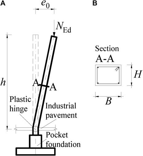
FIGURE 1. Precast column with flexural plastic hinge at the base: (A) elevation and (B) cross-sectional view. Longitudinal reinforcement comprised of four 18 mm-diameter corner bars (As = 1,018 mm2).

TABLE 1. Estimate of the residual drift corresponding to instability under permanent loads for a typical precast RC column (Figure 1) not designed for earthquake resistance.
Therefore, the following retrofitting solutions are strictly tailored to columns not affected by significant permanent drift.
Steel Jacketing
Steel jackets for rectangular RC columns are usually comprised of four angles placed at the corners and a certain amount of horizontal steel strips. These strips, welded to the angles with a certain spacing between one another, are often pre-heated just prior to welding in order to trigger a confinement action on the column.
It is widely recognized (CEN, 2005) that steel jackets may profitably be used in seismic retrofitting of existing RC columns to 1) enhance the shear capacity; 2) prevent failure of lap splices through increased confinement and 3) improve the available curvature ductility in critical regions, once again due to confinement (Figure 2A). In this case, the angles must not necessarily be anchored to the foundation. Several post-earthquake survey reports indicate that the RC pavement, although not mechanically connected with the columns, may play a role in cooperation with the pocket foundation in restraining rotations at the column base. This is testified by evidence showing that at the base of inner columns, where the pavement is present at all sides, the plastic hinge tends to form immediately above the pavement (Liberatore et al., 2013; Minghini et al., 2016; Savoia et al., 2017). Therefore, to enhance curvature ductility at the column base it is sufficient to insert the jacket into the pavement up to midplane.
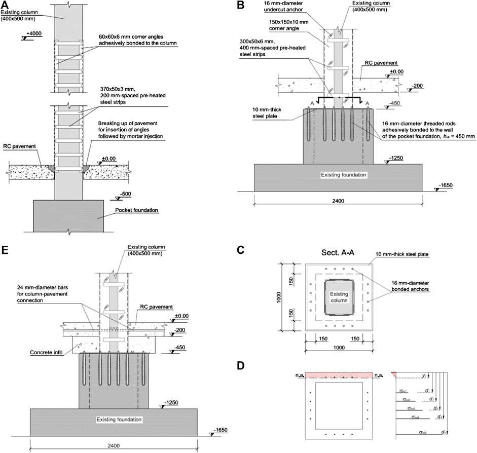
FIGURE 2. Steel jackets applied to precast RC columns: (A) corner angles inserted into the pavement but not anchored to the foundation; (B) jacket connected to the pocket walls by means of bonded anchors, (C) corresponding in-plan anchors arrangement and (D) calculation model for bending resistance of the pocket; (E) the same as (B) plus column-to-pavement connection. Dimensions in mm.
As a possible alternative to the use of steel jackets, Fiber Reinforced Polymer (FRP) plating and wrapping of columns may be used with analogous benefits.
In Northern Italy, particularly after the 2012 Emilia earthquakes, in addition to the three main uses remembered above, steel (and also FRP) jackets are being used to increase the flexural capacity of precast RC columns (Colombo et al., 2012). In this section, we are referred to steel jackets in which the corner angles are attributed the role of longitudinal reinforcement for the column.
The effectiveness of such interventions strictly depends on stiffness and strength of the connection between angles and column. In fact, the angles may be considered as an additional column reinforcement only if they are connected to the column in a manner that the slip at the interface between angles and column is prevented. Moreover, when undergoing compressive stresses, the angles should not suffer early buckling. Therefore, the angle-to-column connections play an even more important role, as well as the spacing of the steel strips. Another essential requirement is that the angles are effectively connected with the foundation. In fact, the angles may serve as an additional column reinforcement at the base, i.e., at the point where the earthquake-induced bending moment in the column takes its maximum, only in the presence of an effective connection with the foundation.
An example showing some of the critical issues raised from steel jacket-to-RC foundation connections is briefly discussed hereinafter. The column shown in Figure 2B, having cross-section dimensions of 400 mm × 500 mm, is considered. The mean values of concrete compressive strength and reinforcing steel yield strength are fcm = 40 MPa and fym = 380 MPa, respectively. A knowledge level KL2 is adopted according to CEN (2005), resulting in a confidence factor CF = 1.2. The column axial compression corresponding to the relevant seismic load combination is NEd = 233 kN. In the absence of any seismic retrofitting, the stress transfer between column and pocket foundation is analogous to that reported by Eurocode 2 (see CEN, 2004a, Fig. 10.7b). Provided that the pocket walls do not experience premature failure due to bending moment and shear load at the column base, the bending resistance of the column due to the existing reinforcement would result to be equal to MRd,c = 236 kN m. The seismic demand in terms of bending moment at the column base is given by MEd = 449 kN m, leading to column safety level ζE = MRd,c/MEd = 0.53. Therefore, it is decided to retrofit the column. To this purpose, a steel jacket comprised of four angles with cross-section dimensions 150 mm × 150 mm × 10 mm and 400 mm-spaced strips was used. Both angles and strips are made of steel of class S 275, with characteristic yield and ultimate strengths of fyk = 275 MPa and ftk = 430 MPa, respectively. At the column base, the angles are welded to steel plates, which are connected to the foundation by means of 16 threaded rods with the diameter of 16 mm (Figure 2C). These rodes are adhesively bonded to the 150 mm-thick pocket walls with an embedment depth of hef = 450 mm.
Such a jacket-to-column connection modifies the stress transfer mechanism between column and pocket foundation. The bending moment and shear force at the column base, particularly in the case of a reduced hole clearance between anchors and steel plate, are now transferred directly to the top of the pocket walls. On the tension side, if the anchors were able to develop the whole yield strength of the angles, the bending resistance at the column base would become MRd,c = 809 kN m, resulting in ζE > 1. However, with regard to the concrete-related failure mechanisms that can develop for the four anchors in tension, the maximum anchored force cannot balance the angle yield force. The design anchored force may be estimated based on the following relation (CEN, 2018):
corresponding to combined pull-out and concrete failure. In Eq. 1, τRk represents the characteristic bond strength, d is the anchor diameter, ratio
with γc = 1.5 and γinst being the usual partial safety factor for concrete and a safety factor related to the installation conditions, respectively. Assuming normal installation safety, γinst = 1.2 in Eq. 2, leading to γMp = 1.8.
For a foundation made of concrete of class C25/30, in the case of cracked concrete and a characteristic bond strength τRk = 7 MPa (a typical value for adhesives available on the market),
where for the reinforcing bars in the foundation the mean yield strength fym = 380 MPa is assumed in analogy with the column reinforcement. Solving Eq. 3 for the tensile stress in the anchors leads to σsd = Nyd,b/(4Ares) = 238 MPa, corresponding to 37% of their nominal yield strength. Recalculating the bending resistance of the foundation for this updated value of σsd yields MRd = 206 kN m and ζE = 0.46. Therefore, the anchorage of the steel jacket to the foundation still represents the weak link in the chain. Being ζE ≤ 0.6, the safety level is insufficient and precludes usability of the building. This feature may become even more critical for all cases in which reinforcement ratio or thickness of the pocket walls are smaller than for the example presented. The strength of the jacket-to-foundation connection should then be improved.
As a first improvement, the intervention shown in Figure 2E is considered. Compared with the previous case, a soil volume between top of the pocket walls and bottom pavement surface is replaced with a concrete infill, and column-to-pavement connections are performed. In particular, three 24 mm-diameter bars per column side are positioned in grooves specially created within the pavement and inserted into the column, to which they are connected through adhesive bonding. On the column tension side, the out-of-plane bending of the base steel plate induced by vertical tension forces in the angles may activate a compression field in the concrete infill, and then in the pavement. This concrete strut will have an approximately vertical direction and will exert a shear force on the bars used for column-to-pavement connection. The associated shear resistance potentially represents an additional contribution to the bending resistance of the foundation.
A further improvement may be obtained by strengthening the pocket walls as shown in Figures 3A,B. To this purpose, the pavement should be demolished around the column to allow for RC jacketing the existing pocket walls. The vertical reinforcement in the new four RC walls provides additional bending strength to the foundation, especially if a sufficient friction between the existing pocket and its jacket is ensured. In this case, inclined compression struts originating from the anchors in tension make activate the vertical reinforcing bars contained in the jacket, providing the foundation with the necessary bending strength. Depending on the vertical reinforcement ratio of the pocket jacket, a capacity design of type “strong foundation-weak column” may be achieved, in which the foundation is given a suitable bending overstrength. This intervention also improves the shear strength of the foundation.
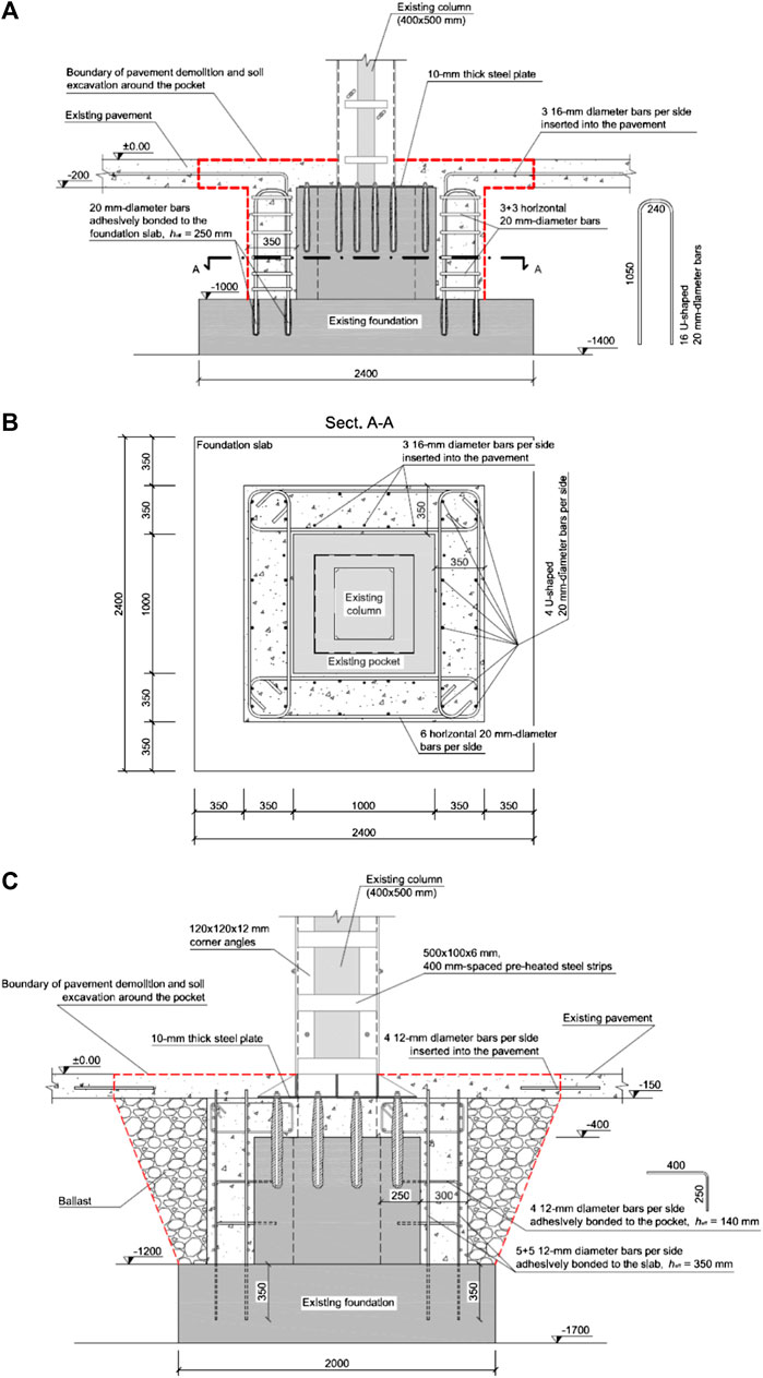
FIGURE 3. Steel jacketing of precast columns in association with foundation strengthening: (A) vertical and (B) horizontal sectional views of pocket strengthened by a cast-in-contact RC jacket; (C) RC jacket applied to the sides and top of the existing pocket walls and connected to them by means of bonded ancors. Dimensions in mm.
In order to enhance the stress transfer within the foundation, a number of mechanical connections between the existing pocket and its RC jacket may be prescribed. Compared with the previous solution, the shear strength of the interface between new and existing concretes now relies not only on the roughness of the interface itself, but also on the area of reinforcement crossing it (see Eq. 6.25 reported by CEN, 2004a). Therefore, the contribution of the vertical reinforcement contained in the pocket jacket is even more likely to be activated. In the proposal shown in Figure 3C, 12 mm-diameter bonded bars are used to connect the new RC jacket to both slab and pocket walls of the existing foundation. Moreover, in addition to the side strengthening, a slab is cast at the same time on the top of the pocket walls, resulting in a column-to-foundation connection emulating a monolithic connection. Before the described interventions of steel jacketing of columns and foundation strengthening, the safety level of the building in terms of capacity-to-demand ratio was of 0.37. The ultimate limit state conditions were governed by columns bending failure. Due to the retrofitting, an increase of 62% in the global safety level is obtained, leading to a capacity-to-demand ratio of 0.6.
RC Jacketing
RC jackets are particularly suited to columns requiring a significant increase of both bending resistance and stiffness. For example, slender columns with b/H < 0.1, with b and H being maximum column cross-section dimension and column height, respectively, may profitably be retrofitted by RC jacketing, becoming less vulnerable to second-order effects. Moreover, also shear strength, ductility of critical regions and strength of deficient lap-splices are usually improved by the presence of a RC jacket. The calculation of enhanced column properties is usually based on the following simplifying assumptions (CEN, 2005):
1) full composite action between new and existing concretes;
2) axial load acting on the entire jacketed column section;
3) concrete properties of the jacket extended to the existing concrete too.
In the case of precast RC columns with pocket foundations, the jacket-to-foundation connection should be designed with particular care to obtain an efficient stress transfer mechanism and full development of the jacket bending resistance.
An intervention proposal is described hereinafter with regard to the precast column shown in Figure 4A, for which the safety verifications indicate insufficient bending resistance, excessive lateral deformability and inadequate confinement at the base due to the presence of stirrups without hooked ends. A concrete jacket reinforced with sixteen 20 mm-diameter bars is then used to retrofit the column. The intervention is carried out in the following steps:
1) pavement demolition around the column;
2) partial soil excavation up to the top surface of the foundation slab;
3) partial demolition of pocket walls,
4) insertion of bonded anchors into the slab (for steps 1 to 4 see Figure 4B);
5) positioning of jacket (longitudinal and transverse) reinforcement (Figure 4C);
6) positioning of vertical reinforcement (Figure 4D) and of
7) horizontal reinforcement (Figure 4E) for foundation strengthening;
8) casting of concrete for both jacket and foundation.
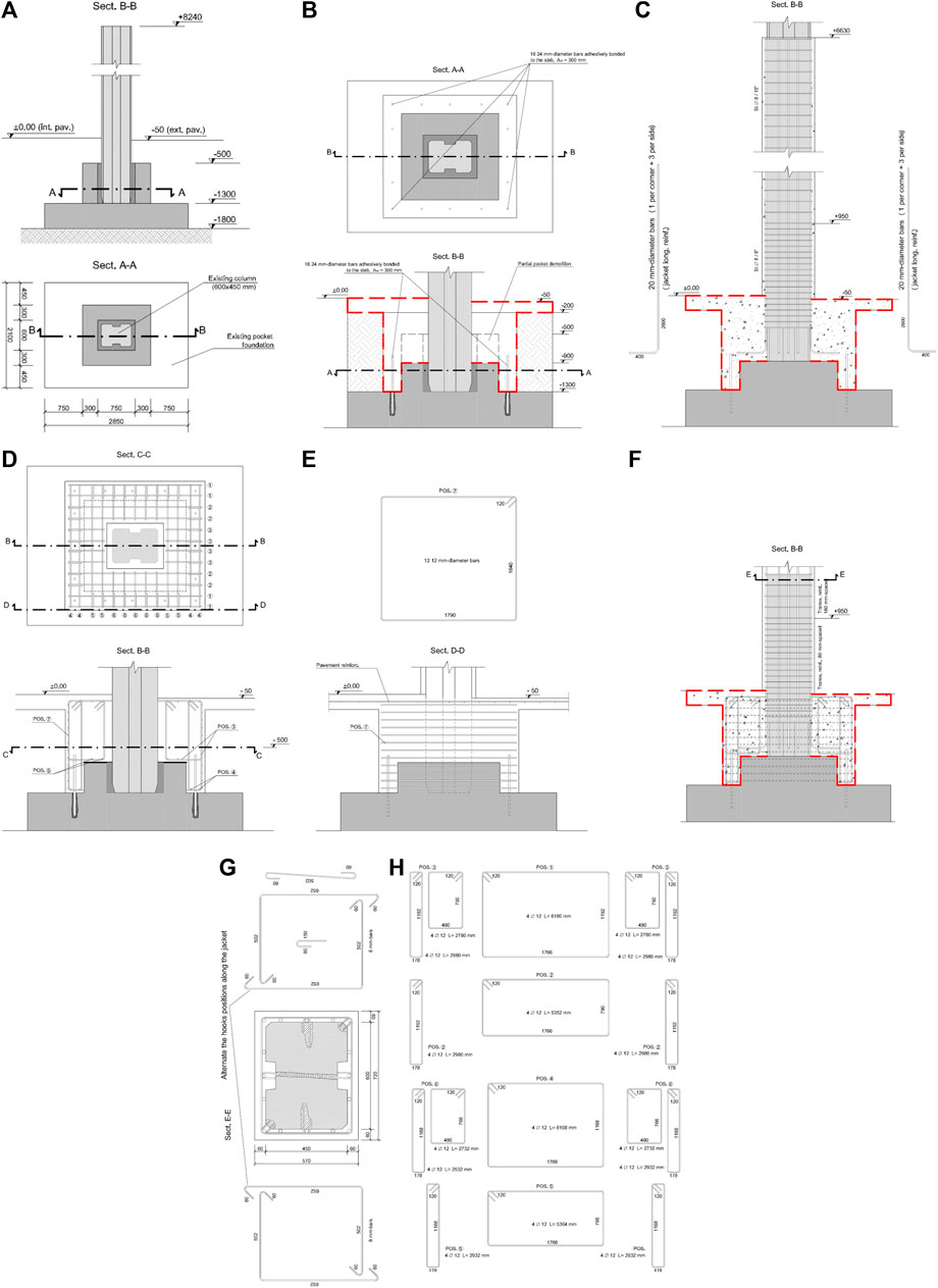
FIGURE 4. (A) Precast RC column needing both flexural strengthening and stiffening; RC jacketing for the column of (A): (B) partial pocket demolition and installation of bonded anchors into the existing slab; (C) positioning of jacket reinforcement; positioning of (D) vertical and (E) horizontal reinforcement for foundation strengthening; details of (F) final column-to-foundation connection, (G) jacketed column cross-section, and (H) foundation vertical reinforcement shown in (D). Dimensions in mm.
The strengthened foundation is a sort of new, better performing pocket foundation and the resulting column-to-foundation connection emulates typical cast-in-place connections (Figure 4F). The confinement action along the critical region at the column base is achieved by means of 80 mm-spaced suitably designed links. In particular, peripheral transverse reinforcement and links crossing the whole column section, or adhesively bonded to it, are used so as to engage one every two longitudinal bars of the jacket (Figure 4G). Construction details for the vertical reinforcement used for foundation strengthening are given in Figure 4H.
The described intervention was proposed for a building located at about 10 km from the epicentre of the first mainshock of the Emilia earthquake. The building reported flexural and shear cracks in some of the columns and severe damages to nonstructural elements. The building capacity-to-demand ratio before the retrofitting was of 0.12. In addition to the application of a RC jacket to all of the columns, the retrofitting included a mass reduction, obtained by replacing the concrete cladding panels with lightweight sandwich panels (see Substitution of Cladding Panels With Lightweight Sandwich Panels section). Disassembling the existing cladding allowed to easily jacket also peripheral columns before the installation of the new cladding system. Due to these interventions, the building safety level increased up to 0.62.
For another precast building, substantially undamaged but characterized by insufficient column reinforcement, analogous interventions were designed. The building is located in the Scientific-Technological campus of the University of Ferrara, at about 40 km from the epicentre. The mass reduction was judged not necessary in this case, being the cladding already comprised of lightweight sandwich panels. However, due to proximity to another structure, there was the need to stiffen, and not only to strengthen, the columns, so as to avoid pounding. Design calculations showed that jacketing only eight of the 21 columns results to be sufficient to ensure an increase of 54% in the safety level, leading to a global safety factor of 0.63.
Column Doubling
For slightly damaged or undamaged buildings, an additional requirement for the seismic retrofitting may sometimes be that the productive activity should not be interrupted during the works. In order to maintain the building fully operational and avoid any interference in production, retrofitting solutions involving building strengthening on the outside only should be preferred.
The solutions shown in Figure 5 are concerned with strengthening each of the existing precast columns of a single-storey industrial building with a new Cast-In-Place (CIP) column joined on the outside. All CIP columns are connected with one another at the base by a new foundation beam. In the proposal reported in Figure 5A, the CIP column has the same cross-section dimensions as the existing column and is connected with it by means of adhesively bonded bars with the diameter of db = 25 mm, entirely crossing the RC cladding panels. These connections should be designed to transfer part of the earthquake induced shear force to the CIP column, which is assumed non-dissipative and results to be heavily reinforced. As an indirect, but not less important benefit, the CIP columns help maintaining the RC cladding panels attached to the building, so that no specific device is required to overcome the panel-to-column connection deficiencies and avoid the out-of-plane collapse of panels. However, due to the presence of a drain pipe in centroidal position in the precast column, the bonded anchors are staggered along the column height and present a minimum edge distance of c = 4db = 100 mm only (Figure 5B). Therefore, especially for the horizontal ground motion component parallel to the cladding panels shown in Figure 5B, a significant connection strength degradation must be expected due to cyclic loading, and the most probable failure mechanism for the anchors will be a splitting failure (Vintzeleou and Tassios, 1987; CEN, 2018). In fact, for c/db ≤ 6 more ductile failure mechanisms involving bar yielding and limited strength degradation are not activated. The strength associated to these mechanisms (Fischinger et al., 2014) would be proportional to the square root of the product of the concrete compressive strength (fc) times the anchor yield strength (fy). However, the concrete cover is too weak to allow for the development of fy. Moreover, the transverse reinforcement of the existing columns, comprised of 6 mm-diameter stirrups with 200 mm spacing, is largely insufficient to balance the shear forces arising in the 25 mm-diameter bonded bars.
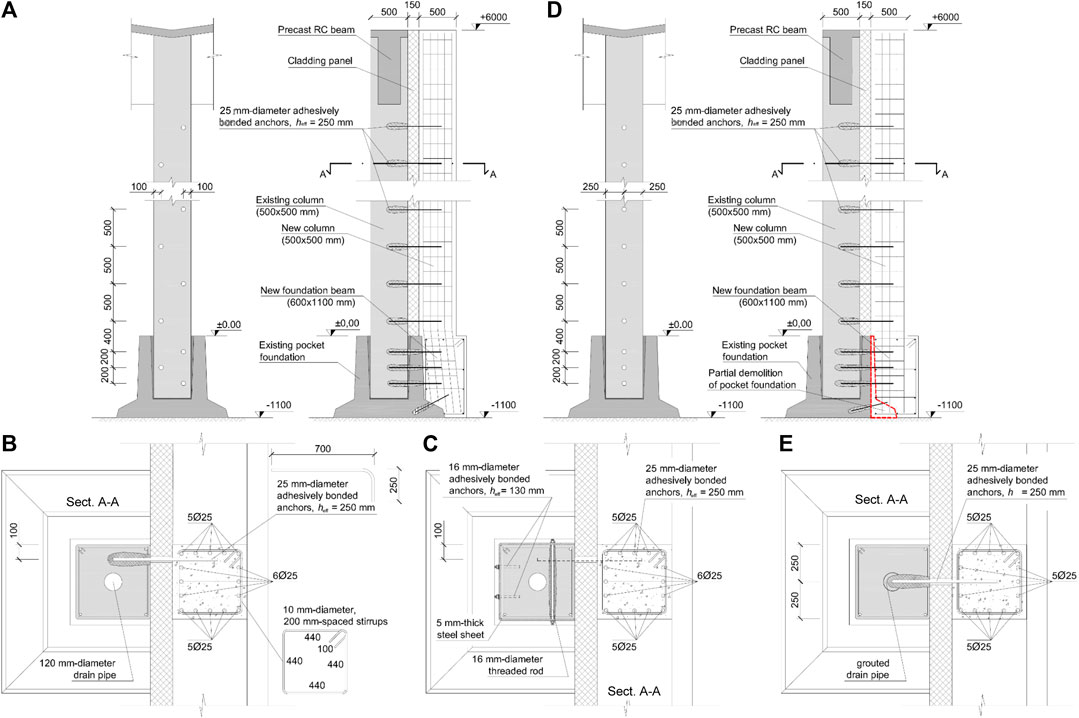
FIGURE 5. Column doubling on the outside: (A) solution preserving the existing foundation with connectors near the column edges and (B) without or (C) with protective metal sheet; (D) solution involving partial demolition of existing foundation and (E) connectors far from edges. Dimensions in mm.
An improved solution is shown in Figure 5C, which proposes the use of a protective steel sheet connected to the existing column on the inside. The steel sheet is designed to act as a dense transverse reinforcement in avoiding premature splitting failure of the existing column. In this case, the dowel action mechanism of the bonded anchors will tend to develop a higher strength. The upper bound of the anchor shear strength associated to such a mechanism can be estimated from the following equation:
with As and fyd representing anchor cross-section area and design yield strength, respectively. It is worth noting that when the concrete in proximity of the dowel is effectively protected against brittle failure, this upper bound may really be achieved and strength degradation due to cyclic loading will be negligible (Tullini and Minghini, 2016). However, the application of steel sheets to the columns may involve interference with the productive activity carried out in the building.
An alternative solution may thus be based on grouting the drain pipe so as to allow for the insertion of adhesively bonded bars into the column in correspondence of the external edge midside (Figures 5D,E). In this case, the edge distance to anchor diameter ratio is c/db = 10, and the maximum dowel action strength may develop without any further intervention.
Bending of starter bars of the strengthening columns may be avoided by partially demolishing the existing pocket foundations (Figure 5D).
The described intervention was proposed for a building located at about 15 km from the epicentre of the second mainshock of the Emilia earthquake. The building reported heavy damages to nonstructural elements and cracks at the base of some of the columns. The column doubling ensures an increase in the safety factor from 0.12 up to 0.6.
Interventions on RC Cladding Panels
It is well known that RC cladding panels may represent a source of significant seismic vulnerability for pre-seismic precast buildings. This is essentially due to the following two reasons:
1) they generally possess a significant mass;
2) their connections to precast columns or beams are not conceived to resist the shear forces due to in-plane seismic action.
Many available researches deal with vulnerability of RC cladding panels (Belleri et al., 2016; Belleri et al., 2018) and possible strategies to mitigate it (Biondini et al., 2013). In this section, two alternative approaches are presented.
Substitution of Cladding Panels With Lightweight Sandwich Panels
The substitution of RC cladding panels with lightweight sandwich panels obviously leads to a reduction of nonstructural masses, which may be significant especially for single-storey buildings. This mass reduction, at equal column stiffnesses, gives rise to a decrease in the fundamental period of the building and then to a demand increase in terms of spectral acceleration. It can be finally shown that, taking account of both mass reduction and acceleration increase, the cladding substitution may yield a decrease in the elastic base shear demand of about 8–15%. This intervention can thus be considered as a full-fledged seismic retrofitting.
For a single-storey building located in the Scientific-Technological campus of the University of Ferrara, Minghini et al. (2015) showed the benefit arising from cladding substitution through a set of nonlinear time-history analyses. Due to increase of confinement by means of steel jackets applied to critical regions of columns (similarly to what is shown in Figure 2A) and global mass reduction obtained from cladding substitution, the 9.5 m-high columns, although designed in origin with no particular seismic provisions, resulted characterized by a very stable cyclic behavior with limited post-peak degradation.
Use of Existing RC Cladding Panels as Shear Walls
This intervention proposal results to be effective in the presence of a roof slab behaving as a rigid diaphragm. For example purposes, the plan view of a precast industrial building is reported in Figure 6A. The 200 mm-thick cladding panels are spanning horizontally between 6 m-spaced columns, and are inserted vertically into specifically suited grooves in the column section.
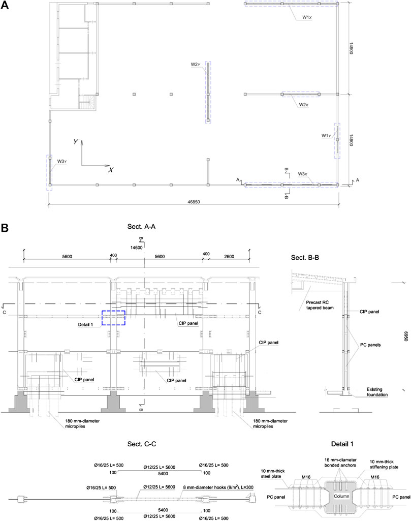
FIGURE 6. RC cladding panels readapted as shear walls: (A) plan view of a building where three shear walls were obtained in both X and Y direction; (B) details for shear wall W3X. Dimensions in mm.
The intervention consists in connecting the panels with one another along their horizontal common edges, and the panel vertical edges with the columns, so as to form a shear wall. For the building shown in Figure 6A, three shear walls are obtained for both X and Y direction. The construction details for one of these walls are reported in Figure 6B. To maximize the stiffening effects of this solution, the openings which were originally present in the cladding panels are filled with CIP concrete, and a dense reinforcement is used to anchor CIP with existing precast concrete. Analogously, new RC panels are cast in the place of missing precast panels. Finally, in order to allow a more rigid and effective connection with micropiles used to strengthen the foundations, a portion of the existing panels at the bottom ends of the walls is cut out and replaced with a CIP panel.
The obtained shear walls can be designed to resist the entire seismic force on the building, so as to leave the columns not belonging to the strengthening system subjected to gravity loads only. Due to the very high ratio of horizontal to vertical loads acting on these walls, the deep foundations at the wall ends may result to be unavoidable to withstand global in-plane rocking.
A key role is played by panel-to-panel and panel-to-column connections, which may determine success or failure of the retrofitting solution. Therefore, a capacity design strategy assigning some overstrength to these connections can be useful. Alternatively, the connections may be attributed the role of dissipating energy by means of properly designed devices (see, for example, Biondini et al., 2013).
The evaluation of design forces may follow equilibrium-based simplified approaches analogous to those reported in Sect. 9 of Eurocode 5 for multi-panel timber structures (CEN, 2004b).
For the building shown in Figure 6, the intervention described leads to an increase of 80% in the safety factor.
New Steel Bracing Systems
Steel bracings may be effective in increasing the seismic resistance of precast buildings, especially for their reduced self weight and relative ease of connection with RC members. These systems are usually designed to resist the whole seismic force acting on the building or a significant portion of it. Two different design strategies should be followed depending of the in-plane stiffness of floor slabs and roof. In the case of rigid slabs and roof, steel bracing systems may be implemented in some “key points” of the building and their stiffening effect is transferred to all precast columns due to the in-plane floor stiffness. In the case of deformable slabs and roof, steel bracings in two orthogonal directions are required for each line of columns. In single-storey precast buildings struck by the Emilia earthquakes, typically featuring deformable roofs, the most used strategy is the latter.
The retrofitting solution shown in Figure 7A features steel frames comprised of I-section columns and beams, braced by diagonal built-up members using two back-to-back channels. These bracings converge into a node which is linked to the precast building in proximity of the beam-column node. The intervention is mainly carried out from the outside, so limiting the disturbance to the productive activity. However, the upper part of the precast column should generally be strengthened to resist the point forces transferred from the bracing system. Due to this intervention, the safety level of the building is increased from 0.09 up to 0.61.
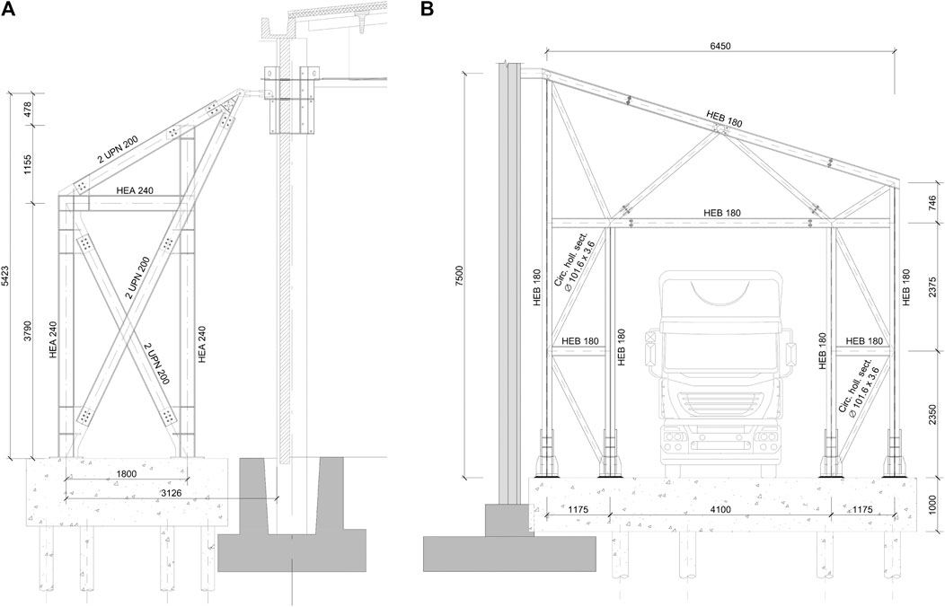
FIGURE 7. Steel bracing systems applied to the outside of single-storey precast RC buildings: (A) single braced frame; (B) frame on laced built-up columns allowing for trucks circulation around the building. Dimensions in mm.
With regard to the analogous solution shown in Figure 7B, the steel frames have two laced columns designed to leave a 4 m wide passage for trucks circulation. An increase in the capacity-to-demand ratio from 0.21 up to 0.63 is obtained in this case.
The steel bracing shown in Figure 8A was proposed for a single-storey precast building with shed-type roof and is comprised by HEA 200 profiles. The bracing effect is ensured by the V-shape. When the building is subjected to lateral forces, the two diagonal profiles experience tensile and compressive axial loads. Provided that the bracing remains within the elastic range, and the compressed profile does not buckle, the sum of the vertical components of these loads tends to vanish. Therefore, the new foundation into which the diagonal profiles are converging must essentially be checked against sliding. Detail views of the bracing-to-column and bracing-to-foundation connections are shown in Figures 8B,C, respectively. Due to the described intervention, the building safety level increases from 0.20 to 0.68.
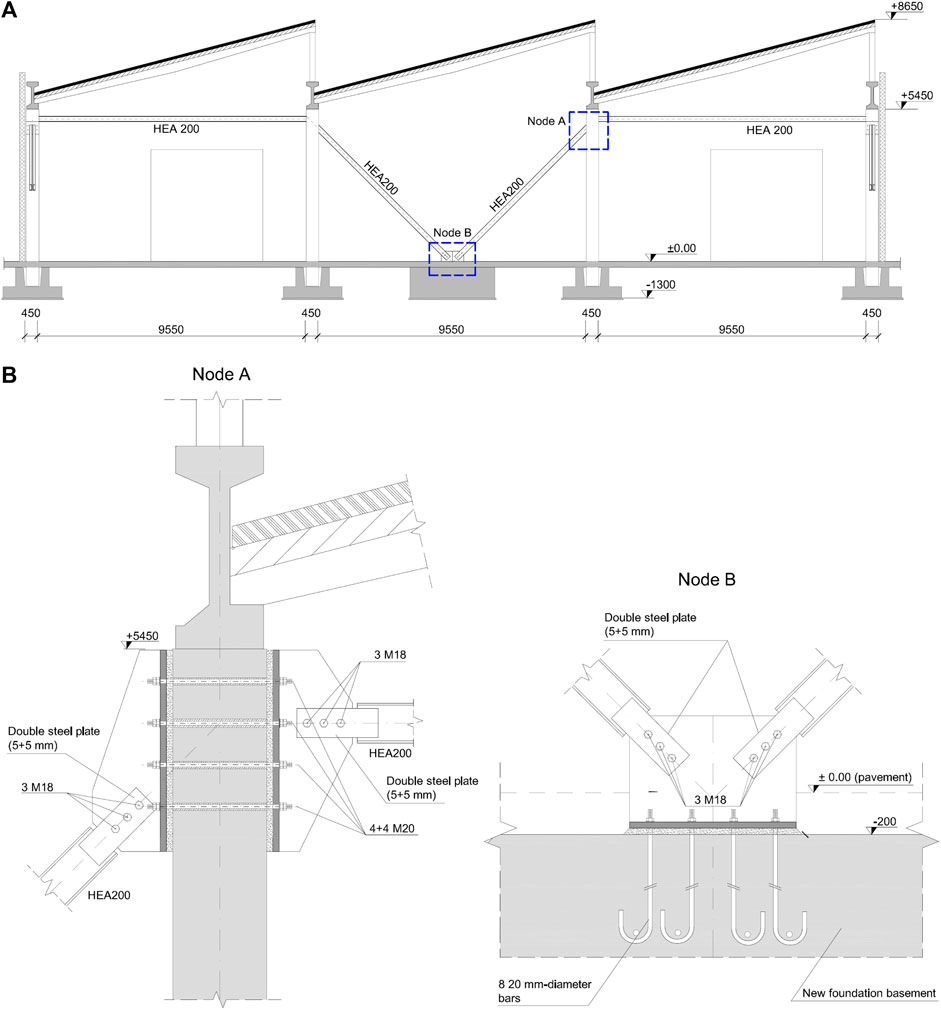
FIGURE 8. V-shaped steel bracing used to stiffen four columns in a precast building with shed-type roof: (A) front view; detail view of (B) bracing-to-column and (C) bracing-to-foundation nodes. Dimensions in mm.
The retrofitting solution presented in Figure 9 was applied to a two-storey office building. The cladding panels of the building are made of precast concrete, whereas beams, columns and floor slabs are cast-in-place. However, the slabs do not behave as rigid diaphragms. Thus, the overall building response to seismic actions is analogous to that of the most of the precast buildings in the struck territory. For this reason, one plane braced frame is used for each line of columns in two orthogonal directions (Figures 9A,B). These plane frames, made of circular hollow section profiles, are restrained in the transverse direction against buckling. The connections with the building are positioned in correspondence of the floor and roof slabs (Figure 9C). Reported in Figure 9D are the construction details of node A highlighted in Figure 9B. The safety level of the building before the interventions was of 0.2. Due to an explicit request of the building owner, the target capacity adopted in retrofitting design was comparable to that prescribed for new buildings.
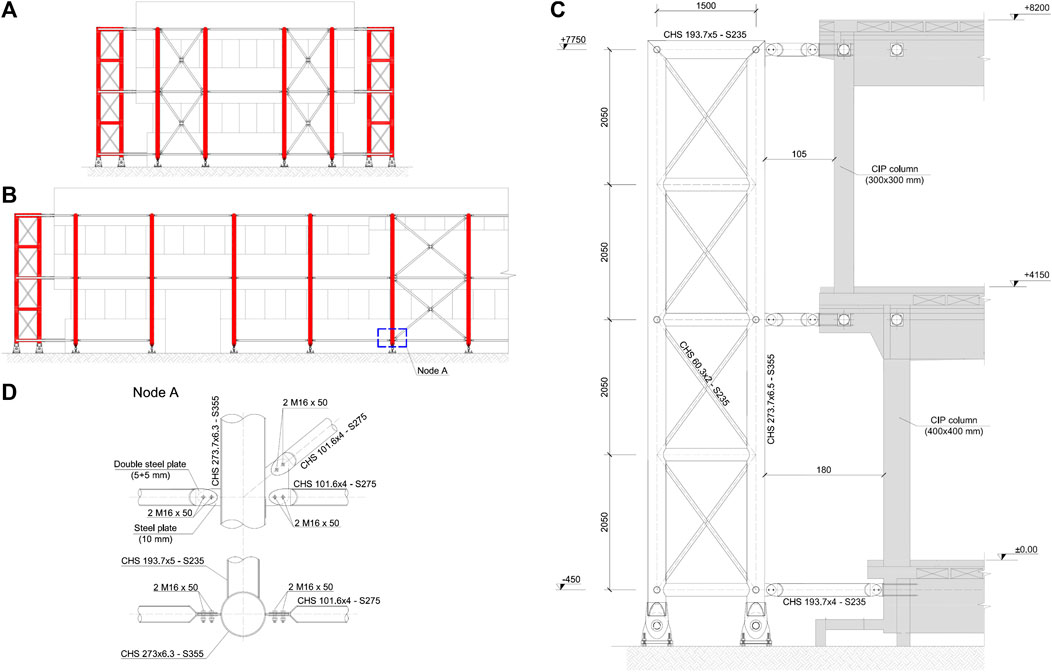
FIGURE 9. Spatial steel bracing system applied to a two-storey building: (A),(B) building front views; (C) lateral view of one of the truss frames of the bracing system comprised of circular hollow section profiles and (D) detail view of a node. Dimensions in mm.
Finally, the proposal shown in Figure 10 relies upon the use of steel portal frames at the outside of the building to be retrofitted. The laced built-up columns of these frames are positioned adjacent to the existing RC columns (Figure 10A) and connected to them in proximity of their top end section. The cross-section depth of the steel columns increases with the elevation above the soil level in order to save space for vehicular traffic around the building. Pinned connections are adopted at the base of the steel columns because of practical difficulties in obtaining moment-resisting joints. Then, the in-plane bracing effect exerted by steel frames on the building is ensured by bending stiffness and strength of the nodes between laced columns and 1.6 m-deep truss beams. The portal frames are connected to one another, so forming a unique three-dimensional truss structure (Figure 10B). In particular, the steel columns are stiffened in the transverse direction by peripheral truss beams, whereas the top chords of the main beams are braced by the stabilizing effect due to inclined ties and purlins. Also in this case a unity safety factor is obtained due to retrofitting, whereas the pre-interventions capacity-to-demand ratio was of 0.1.
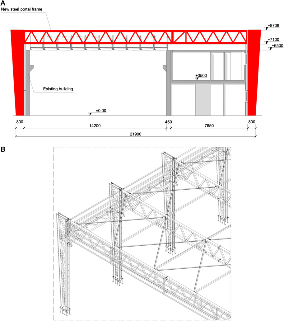
FIGURE 10. Steel portal frames with laced built-up columns and truss beams used as earthquake resistant system at the outside of an existing precast building: (A) cross-sectional view of the building after the intervention; (B) three-dimensional view of the new steel structure. Dimensions in mm.
Effect of Roof Stiffening: Some Consideration
The distribution of seismic forces among columns depends of the in-plane stiffness of floor slabs and roof. For example, in typical single-storey buildings featuring in-plane deformable roof comprised of precast elements independent of one another and simply-supported on precast frames, the seismic forces on columns are mass proportional. If Fh indicates the overall seismic force orthogonal to the roof elements and k the number of roof spans, the forces acting on perimeter (Fdef,p) and internal precast frames (Fdef,i) can be evaluated from:
Conversely, in the case of in-plane rigid roof the overall seismic force is distributed among columns in proportion to their translational stiffness. Then, if the roof is stiffened so as to behave as a rigid diaphragm, the columns are identical to one another, and Fh is assumed to be unchanged (although stiffening has in general the effect of reducing the periods of vibration and then increasing the shear demand), the expressions for forces acting on perimeter (Frig,p) and internal frames (Frig,i) take the form:
Therefore, roof stiffening leads to a reduction of shear demand on internal frames and to an increase of shear demand on perimeter frames. These shear force variations are given by:
for internal and perimeter frames, respectively, and are reported divided by the corresponding forces for deformable roof (Fdef,i, Fdef,p) in Figure 11 vs. k. It can be noted that the effect of roof stiffening on perimeter frames is much more pronounced and increases with k. For example, for a building with k = 4 roof spans, the roof stiffening would yield an increase in shear demand on perimeter frames of 60% and a corresponding decrease in shear demand on internal frames of 20%. Retrofitting solutions involving an increase of roof stiffness could then require a strengthening of perimeter columns and should be assessed with care.
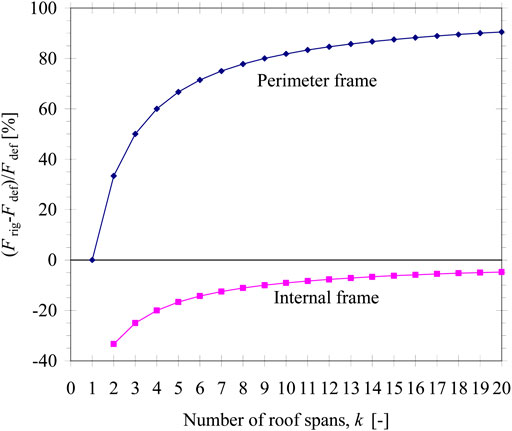
FIGURE 11. Influence of roof stiffening on seismic forces acting on perimeter and internal frames.
Another issue related with roof in-plane stiffness is concerned with roofs comprised of Pi-shaped precast elements. This type of roof is quite common among industrial buildings struck by the 2012 earthquakes in Northern Italy. In Italian pre-seismic buildings the roof elements were often simply supported on the main beams without any mechanical connection device. In Emilia, the 2012 earthquake sequence caused the roof unseating in many buildings near the epicentres of the two mainshocks, highlighting the inadequacy of these friction-based connections. Immediately after the second mainshock, to avoid loss-of-support collapses at a larger scale in the struck territory and ensure the temporary usability of the buildings, Legislative Decree No. 74 (2012) imposed to remove all connection deficiencies by introducing suitable devices. For roofs comprised of Pi-shaped precast elements, the roof-to-beam connections were frequently strengthened by anchoring to the beam, at each support, both webs of each roof element. This intervention implies an increase of the roof stiffness, because the Pi-shaped elements become able to transfer, in the plane of the roof, bending moments to the beams through tensile and compressive forces arising in the webs.
For example purposes, the precast building shown in Figure 12A,B is analyzed through the Response Spectrum Method (RSM). The building has in-plan dimensions of about 60 m × 24 m. The columns are mainly placed on the perimeter. In particular, the column along the longest sides have cross-section dimensions of 600 mm × 700 mm, height of 9.5 m and spacing of 10 m. The main beams are spanning parallel to the longest building sides and support a roof with the span of 24 m comprised of 1 m-deep prestressed Pi-shaped elements. Beam Finite Elements (FE) are used for column, beams and cladding panels. In order to reproduce accurately the roof vibration, the Pi-shaped elements are modeled using shell FE (Figure 12C,D). Three different models are obtained by changing the way the roof elements are connected to the beams (Table 2). In Model #1, only one of the webs of the roof elements (say, web A in Figure 12C) is connected at each of the supporting beams. These connections are assumed to be pinned in both vertical and horizontal plane. In Model #2, each roof element is connected to the beams through web A at one end and web B at the other end. Finally, in Model #3 both webs are connected to the supporting beam at each end (Figure 12D). The resulting fundamental periods and maximum tensile forces in the webs of the roof elements are reported in Table 3. These forces should be used to design the roof-to-beam connections, but are not the sole forces to be considered. In fact, due to the usual combination rules for horizontal ground motion components, the roof-to-beam connections are subjected to combined tensile and shear loads.
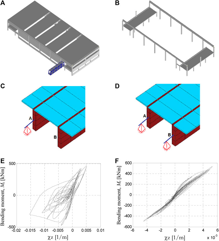
FIGURE 12. FE model of a precast building located in the Scientific-Technological campus of the University of Ferrara: global model (A) showing and (B) hiding roof elements and cladding panels; end support of a Pi-shaped roof element with connections to the main beams applied to (C) one single web or (D) both webs. Moment-curvature cyclic diagram at the base of one of the columns obtained from NRH analysis (E) before and (F) after retrofitting.
TABLE 2. FE models of the bulding in Figures 12A,B obtained for different methods of connection of the precast Pi-shaped roof elements with the main beams.
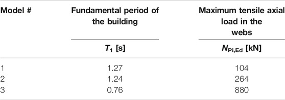
TABLE 3. Effect of the roof element-to-main beam connections on fundamental period of the building and design tensile load acting on the anchorage.
While the fundamental period remains substantially unchanged in the passage from Model #1 to Model #2, a significant stiffening effect is observed for Model #3. The type of connection dramatically affects the web forces, which for Models #2 and #3 result to be 2.6 and 8.8 times larger, respectively, than those obtained for Model #1. The reason for the force increase observed for Model #2 should be searched in the fact that when different webs are connected to the supporting beams the Pi-shaped elements may be viewed as inclined trusses subjected to tension and compression. The huge tensile forces obtained for connections in Model #3 make them impractical in that case. In other words, it is not economically sustainable to stiffen the roof by acting on the roof-to-beam connections only. It is concluded that to avoid excessive design load demands the connections should ensure an isostatic behavior of the roof in both vertical and horizontal plane.
Discussion
The safety factors reported in Critical Analysis of Retrofitting Interventions were extracted from the database implemented by Minghini et al. (2016). The information collected derives from reports prepared by engineers hired by the companies to design retrofitting interventions. Linear elastic seismic analyses based on the RSM were generally adopted in these reports. This may result in a too conservative design approach, sometimes involving overdesigned interventions and corresponding unnecessary costs. A better approximation of the building earthquake response, both pre- and post-interventions, can be obtained using Nonlinear Response History (NRH) analyses. This kind of analysis is very demanding from a computational point of view and still remains restricted to research.
For the building shown in Figures 12A,B, in addition to strengthening connections between roof elements and main beams, the retrofitting interventions are comprised of 1) substitution of existing RC cladding with lightweight panels (see Substitution of Cladding Panels With Lightweight Sandwich Panels section) and 2) increase in the confinement of columns critical regions with the use of steel jackets (Figure 2A). Based on RSM analysis, the acceleration based capacity-to-demand ratio for the building increases from 0.57 (before interventions) to 0.85 (after interventions). These safety factors are calculated adopting mean values of concrete and steel strengths and a coefficient of 0.5 reducing the columns stiffness to account for cracking. Yet, NRH analysis results show that the post-interventions safety level of the building is greater than required for new buildings. The seismic input is applied in the form of seven sets of natural accelerograms, selected and scaled to achieve compatibility with the elastic response spectrum provided by the Italian Building Code (IMIT, 2018). Reported in Figures 12E,F are moment-curvature cyclic diagrams for one of these sets obtained for a column from NRH analysis of the building before and after interventions, respectively. The beneficial effect due to mass reduction is evident from the plots. In particular, the damage highlighted by the hysteresis cycles in Figure 12E is not present in the column after interventions (Figure 12F), which substantially remains undamaged.
Conclusion
Retrofitting solutions for precast buildings struck by the 2012 Emilia, Italy, earthquakes are examined in this paper. The described interventions are divided into three categories: 1) column strengthening; 2) interventions on cladding panels, and 3) use of steel bracing systems.
With regard to the first category, it is shown that column strengthening either by steel or RC jacketing generally needs to be combined with strengthening of the pocket foundation. This is essentially due to the poor reinforcement ratio of existing pocket walls, which are unable to anchor adequately the reinforcement added to the column. Moreover, when new columns are joined to the existing ones to increase the overall building capacity, an effective connection should be obtained by avoiding stress concentrations in the concrete cover.
With regard to the second category, two completely different approaches are analyzed. The first approach proposes the substitution of RC cladding with sandwich panels. In this case, the increase in building safety is related with the mass reduction. The second approach makes use of the existing cladding panels to create very stiff shear walls. Obviously this solution requires a preliminary intervention to make the roof a rigid diaphragm.
With regard to the third intervention category, various solutions are examined. Most of them are based on steel bracing systems positioned on the outside of the buildings, so allowing for the continuation of the productive activities during the installation works. The bracing systems are usually designed to withstand the entire (or a significant portion of the) base shear demand on the building. Therefore, the zones where the bracing are connected to the existing structure must be protected against stress concentrations. A solution suitable for two-storey buildings is also presented.
Finally, some consideration on the effects due to roof stiffening is reported. In particular, it is shown that roof stiffening may lead to a significant increase in the base shear demand on perimeter columns. In addition, for roofs comprised of Pi-shaped precast elements, connecting both webs of each element to the supporting beams may yield excessive design forces, resulting in impractical connections.
For several retrofitting solution, the increase obtained in the building safety level is reported. These safety measures, obtained from linear analyses, underestimate the actual safety of the building. A proof of this statement is provided for a case study, for which nonlinear response history analyses are also carried out. These analyses indicate that, due to retrofitting, the building may reach a seismic resistance greater than prescribed for new buildings, although preliminary linear analyses led to a significantly smaller safety level.
Data Availability Statement
The original contributions presented in the study are included in the article, further inquiries can be directed to the corresponding author.
Author Contributions
All authors listed have made a substantial, direct, and intellectual contribution to the work and approved it for publication.
Funding
The present investigation was developed in the framework of the Research Program FAR 2020 of the University of Ferrara. Moreover, the analyses were carried out within the activities of the (Italian) University Network of Seismic Engineering Laboratories–ReLUIS in the research program funded by the (Italian) National Civil Protection—Progetto Esecutivo 2019/21—WP2, Unique Project Code (CUP) F54I19000040005.
Conflict of Interest
The authors declare that the research was conducted in the absence of any commercial or financial relationships that could be construed as a potential conflict of interest.
Acknowledgments
The contributions of Alice Vincenzi and Mirko Gallerani to the preparation of drawings of the construction details analyzed in the present study are gratefully acknowledged.
References
Belleri, A., Brunesi, E., Nascimbene, R., Pagani, M., and Riva, P. (2015a). Seismic performance of precast industrial facilities following major earthquakes in the Italian Territory. J. Perform. Constr. Facil. 29, 04014135. doi:10.1061/(asce)cf.1943-5509.0000617
Belleri, A., Cornali, F., Passoni, C., Marini, A., and Riva, P. (2018). Evaluation of out-of-plane seismic performance of column-to-column precast concrete cladding panels in one-storey industrial buildings. Earthq. Eng. Struct. Dyn. 47 (2), 397–417. doi:10.1002/eqe.2956
Belleri, A., Labò, S., Marini, A., and Riva, P. (2017). The influence of overhead cranes in the seismic performance of industrial buildings. Front. Built Environ. 3, 64. doi:10.3389/fbuil.2017.00064
Belleri, A., Torquati, M., Marini, A., and Riva, P. (2016). Horizontal cladding panels: in-plane seismic performance in precast concrete buildings. Bull. Earthq. Eng. 14, 1103–1129. doi:10.1007/s10518-015-9861-8
Belleri, A., Torquati, M., Riva, P., and Nascimbene, R. (2015b). Vulnerability assessment and retrofit solutions of precast industrial structures. Earthq. Struct. 8 (3), 801–820. doi:10.12989/eas.2015.8.3.801
Biondini, F., Dal Lago, B., and Toniolo, G. (2013). Role of wall panel connections on the seismic performance of precast structures. Bull. Earthq. Eng. 11, 1061–1081. doi:10.1007/s10518-012-9418-z
Bournas, D. A., Negro, P., and Taucer, F. F. (2014). Performance of industrial buildings during the Emilia earthquakes in Northern Italy and recommendations for their strengthening. Bull. Earthq. Eng. 12, 2283–2404. doi:10.1007/s10518-013-9466-z
Bovo, M., and Savoia, M. (2019). Evaluation of force fluctuations induced by vertical seismic component on reinforced concrete precast structures. Eng. Struct. 178, 70–87. doi:10.1016/j.engstruct.2018.10.018
Buratti, N., Minghini, F., Ongaretto, E., Savoia, M., and Tullini, N. (2017). Empirical seismic fragility for the precast RC industrial buildings damaged by the 2012 Emilia (Italy) earthquakes. Earthq. Eng. Struct. Dyn. 46, 2317–2335. doi:10.1002/eqe.2906
Casotto, C., Silva, V., Crowley, H., Nascimbene, R., and Pinho, R. (2015). Seismic fragility of Italian RC precast industrial structures. Eng. Struct. 94, 122–136. doi:10.1016/j.engstruct.2015.02.034
CEN (2004a). EN 1992-1-1:2004. Eurocode 2: design of concrete structures–part 1-1: general rules and rules for buildings. Brussels, Belgium: European Committee for Standardization.
CEN (2004b). EN 1995-1-1:2004. Eurocode 5: design of timber structures–Part 1-1: general-common rules and rules for buildings. Brussels, Belgium: European Committee for Standardization.
CEN (2005). EN 1998-3:2005. Eurocode 8: design of structures for earthquake resistance–part 3: assessment and retrofitting of buildings. Brussels, Belgium: European Committee for Standardization.
CEN (2018). EN 1992-4:2018. Eurocode 2: design of concrete structures–part 4: design of fastenings for use in concrete. Brussels, Belgium: European Committee for Standardization.
Clementi, F., Scalbi, A., and Lenci, S. (2016). Seismic performance of precast reinforced concrete buildings with dowel pin connections. J. Build. Eng. 7, 224–238. doi:10.1016/j.jobe.2016.06.013
Colombo, A., Ronchetti, A., Cardinale, G., Mariani, M., Gambuzzi, A., Dolce, M., et al. (2012). Guidelines for local and global interventions on single-story industrial buildings not designed with anti-seismic criteria working Group for seismic usability assessment of industrial buildings. Available at: www.reluis.it (Accessed September 1, 2020) [in Italian].
Dal Lago, B., Toniolo, G., and Lamperti Tornaghi, M. (2016). Influence of different mechanical column-foundation connection devices on the seismic behaviour of precast structures. Bull. Earthq. Eng. 14, 3485–3508. doi:10.1007/s10518-016-0010-9
Emilia-Romagna Regional Decree No. 57 (2012). Emilia-Romagna regional decree No. 57/2012. Available at: https://www.regione.emilia-romagna.it/terremoto/gli-atti-per-la-ricostruzione/2012/ (Accessed October 30, 2020) [in Italian].
Ercolino, M., Magliulo, G., and Manfredi, G. (2016). Failure of a precast RC building due to Emilia-Romagna earthquakes. Eng. Struct. 118, 262–273. doi:10.1016/j.engstruct.2016.03.054
FEMA 356 (2000). Prestandard and commentary for the seismic rehabilitation of buildings. Washington, DC: Federal Emergency Management Agency.
Fischinger, M., Zoubek, B., and Isaković, T. (2014). “Seismic response of precast industrial buildings,” in Perspectives on European earthquake engineering and seismology, geotechnical, geological and earthquake engineering. Editor A. Ansal (London, United Kingdom: Springer), Vol. 34, 131–177. doi:10.1007/978-3-319-07118-3_4
IMIT (Italian Ministry of Infrastructure and Transport) (2018). Italian building code-D.M. 17/01/2018. Rome, Italy: IMIT [in Italian].
Legislative Decree No.74 (2012). Italian parliament. Available at: https://www.gazzettaufficiale.it/eli/id/2014/06/28/14A04940/sg (Accessed November 3, 2020) [in Italian].
Liberatore, L., Sorrentino, L., Liberatore, D., and Decanini, L. D. (2013). Failure of industrial structures induced by the Emilia (Italy) 2012 earthquakes. Eng. Fail. Anal. 34, 629–647. doi:10.1016/j.engfailanal.2013.02.009
Magliulo, G., Ercolino, M., Petrone, C., Coppola, O., and Manfredi, G. (2014). The Emilia earthquake: seismic performance of precast reinforced concrete buildings. Earthq. Spectra 30, 891–912. doi:10.1193/091012eqs285m
Maugeri, M., Abate, G., Aversa, S., Boldini, D., Dezi, F., Fioravante, V., et al. (2013). Guidelines for interventions on single-story industrial buildings struck by the May 2012 Po River Plain earthquake and not designed with anti-seismic criteria: geotechnical aspects. working group of the Italian geotechnical association (AGI) for the industrial buildings. Available at: www.ateservizi.it (Accessed September 1, 2020). [in Italian].
Mezzapelle, P. A., Scalbi, A., Clementi, F., and Lenci, S. (2017). The influence of dowel-pin connections on the seismic fragility assessment of RC precast industrial buildings. Open Civ. Eng. J. 11 (Suppl. 5, M8), 1138–1157. doi:10.2174/1874149501711011138
Minghini, F., Ongaretto, E., Ligabue, V., Savoia, M., and Tullini, N. (2016). Observational failure analysis of precast buildings after the 2012 Emilia earthquakes. Earthq. Struct. 11, 327–346. doi:10.12989/eas.2016.11.2.327
Minghini, F., Piccoli, F., Rizzato, N., and Tullini, N. (2015). “Assessment of the seismic retrofitting for two precast RC buildings using nonlinear time-history analyses,” in Opensees days Italy, Ferrara, Italy, June 10–11, 2015 (Fisciano, Italy: University of Salerno).
Poiani, M., Gazzani, V., Clementi, F., and Lenci, S. (2020). Aftershock fragility assessment of Italian cast-in-place RC industrial structures with precast vaults. J. Build. Eng. 29, 101206. doi:10.1016/j.jobe.2020.101206
Pollini, A. V., Buratti, N., and Mazzotti, C. (2018). Experimental and numerical behaviour of dissipative devices based on carbon-wrapped steel tubes for the retrofitting of existing precast RC structures. Earthq. Eng. Struct. Dyn. 47 (5), 1270–1290. doi:10.1002/eqe.3017
Rossi, L., Holtschoppen, B., and Butenweg, C. (2019). Official data on the economic consequences of the 2012 Emilia-Romagna earthquake: a first analysis of database SFINGE. Bull. Earthq. Eng. 17, 4855–4884. doi:10.1007/s10518-019-00655-8
Rossi, L., Stupazzini, M., Parisi, D., Holtschoppen, B., Ruggieri, G., and Butenweg, C. (2020). Empirical fragility functions and loss curves for Italian business facilities based on the 2012 Emilia-Romagna earthquake official database. Bull. Earthq. Eng. 18, 1693–1721. doi:10.1007/s10518-019-00759-1
Savoia, M., Buratti, N., and Vincenzi, L. (2017). Damage and collapses in industrial precast buildings after the 2012 Emilia earthquake. Eng. Struct. 137, 162–180. doi:10.1016/j.engstruct.2017.01.059
Tullini, N., and Minghini, F. (2016). Grouted sleeve connections used in precast reinforced concrete construction-experimental investigation of a column-to-column joint. Eng. Struct. 127, 784–803. doi:10.1016/j.engstruct.2016.09.021
Tullini, N., and Minghini, F. (2020). Cyclic test on a precast reinforced concrete column-to-foundation grouted duct connection. Bull. Earthq. Eng. 18, 1657–1691. doi:10.1007/s10518-019-00766-2
Keywords: seismic retrofitting, precast building, industrial building, jacketing, steel bracing, Emilia earthquake
Citation: Minghini F and Tullini N (2021) Seismic Retrofitting Solutions for Precast RC Industrial Buildings Struck by the 2012 Earthquakes in Northern Italy. Front. Built Environ. 7:631315. doi: 10.3389/fbuil.2021.631315
Received: 19 November 2020; Accepted: 05 January 2021;
Published: 05 February 2021.
Edited by:
Andrea Belleri, University of Bergamo, ItalyReviewed by:
Francesco Clementi, Marche Polytechnic University, ItalyDaniele Perrone, University Institute of Higher Studies in Pavia, Italy
Copyright © 2021 Minghini and Tullini. This is an open-access article distributed under the terms of the Creative Commons Attribution License (CC BY). The use, distribution or reproduction in other forums is permitted, provided the original author(s) and the copyright owner(s) are credited and that the original publication in this journal is cited, in accordance with accepted academic practice. No use, distribution or reproduction is permitted which does not comply with these terms.
*Correspondence: Fabio Minghini, ZmFiaW8ubWluZ2hpbmlAdW5pZmUuaXQ=