 Martijn Schildkamp
 Stefano Silvestri
 Yoshikazu Araki
- 1Smart Shelter Research, Alphen aan den Rijn, Netherlands
- 2Department of Civil, Chemical, Environmental and Materials Engineering, University of Bologna, Bologna, Italy
- 3Graduate School of Environmental Studies, Nagoya University, Nagoya, Japan
Full base shear seismic demand analyses with calculated examples for heavy stone masonry buildings are not present in the literature. To address this shortcoming, analyses and calculations are performed on nominally reinforced rubble stone masonry house and school designs, as typically built in Nepal. The seismic codes are literally applied for countries where the technique is still allowed (Nepal, India, China, Tajikistan, Iran, Croatia), or should be reintroduced based on current practices (Pakistan, Afghanistan, Turkey). First, this paper compares the base shear formulas and the inertia forces distributions of these codes, as well as material densities, seismic weights, seismic zoning, natural periods of vibration, response spectra, importance factors and seismic load combinations. Large differences between approaches and coefficients are observed. Then, by following Equivalent Lateral Force-principles for Ultimate Limit State verifications (10%PE50y), the base shear and story shears are calculated for a design peak ground acceleration of 0.20 g, as well as the effects of critical load combinations on the forces and moments acting on the lateral-resisting elements. It is concluded that Pakistan has the most tolerant code, Nepal represents an average value, whereas India and China are most conservative toward the case study buildings. Overall, it is observed that heavy-masonry-light-floor systems with negligible diaphragm action behave different under seismic motion than most other building typologies. Given the observations in this paper, the applicability of conventional ELF, S-ELF and S-Modal methods for heavy masonry buildings is questionable. The codes however do not introduce modified approaches that address these differences. Possible implications of the exclusion of plinth masonry and large portions of seismic weight need further assessment and validation, for which different (possibly more sophisticated) concepts must be considered, such as the equivalent frame method or distributed mass system. Since Nepal allows stone masonry in areas with higher seismic hazard levels >0.40 g (opposed to India <0.12 and China <0.15 g), their code is taken as the reference and starting point for follow-up research, which aims to verify the seismic demand by performing seismic capacity checks of the masonry piers and spandrels. The paper ends with an appeal for global collaboration under the research project SMARTnet.
Introduction
Between 2007 and 2012 the Dutch NGO Smart Shelter Foundation (SSF) built earthquake-resistant schools in rubble stone masonry in Nepal, which have survived the 2015 Gorkha earthquakes without any significant damage. The designs follow general rules of thumb, as found in practical field manuals that address “non-engineered seismic design”. The term “non-engineered” for buildings refers to “those which are spontaneously and informally constructed in various countries in the traditional manner, without any or little intervention by qualified architects and engineers in their design” (Arya, 2000).
However, in-depth technical verifications or validated calculations for stone masonry buildings are not available in the literature nor national codes. The empirical knowledge is based on a few publications from the 1980s which have not been updated since, as concluded by Schildkamp and Araki (2019a). It was already noted in 1977 that “a review of the earthquake codes of various countries shows that much of the information is empirically based and not theoretically derived. In that respect, the recommendations must be subject to continuous review and change as more data become available” (Arya, 1977). Furthermore, Bertero and Bertero (2002) state that “codes and standards should be simple enough so that they can be applied effectively according to the education (knowledge) of the professionals involved (designers, builders, governmental bodies) as well as the owners, but without compromising the reliability of the structure. (…) Codes should reflect the most reliable procedures that can be developed according to the state-of-the-art in seismic engineering.” Effectively, for “non-engineered” structures this has not been undertaken to date, and therefore the authors of this paper have started a long-term research program with the aim of upgrading the knowledge and improving the seismic resilience of rubble stone masonry buildings, to be published in a series of papers that already includes a literature review of practical manuals, a detailed cost analysis (Schildkamp and Araki, 2019a; 2019b) and an overview of design specifications in national seismic and masonry codes worldwide (Schildkamp et al., 2020).
This fourth paper analyzes and compares the seismic demand in terms of total base shear and the load combinations for Ultimate Limit State (ULS) verifications, as dictated in the seismic codes. This is done for those countries where this technique is still allowed, plus selected countries where it potentially could (or should) be reintroduced based on current practices and needs. The analyses are carried out with specific focus on “nominally reinforced masonry (NRM) that consists of random rubble stone with cement mortar and wooden diaphragms,” as detailed in Schildkamp et al. (2020). Random rubble refers to stones that are uncut, unsquared, irregularly shaped and un-dimensioned, whereas NRM refers to loadbearing masonry walls with the inclusion of nominal reinforcements; in this case continuous horizontal bands. Following the philosophies of Arya and Bertero and Bertero, and in the spirit of “non-engineered seismic design,” a simplified approach performed by hand calculations is preferred wherever possible, as opposed to computer-aided modeling.
Many comparisons between seismic codes are found in the literature between a countries’ national code and leading codes from the US, Europe, Japan and New Zealand, such as for India (Dhanvijay et al., 2015), Pakistan (Ali et al., 2017), Azerbaijan (Zeynalov et al., 2013) or Iran (Imashi and Massumi, 2011). A more regional approach compares the situation between neighboring countries, for example Nepal with India (Neupane and Shreshta, 2015) and China (Tamrakar and Chen, 2017), or Russia with Armenia and Uzbekistan (Mukhadze and Timchenko, 2000). Overall, the following generalities are observed. Firstly, most studies focus on particular segments, formulas or design parameters within the codes (for instance Xiaoguang et al., 2012 who compare eight Asian countries), but they do not cover the complete design process of a particular building type or technique. Secondly, when a calculation example is included, these are almost exclusively for medium-to-high-rise buildings with concrete or steel frames (Khose et al., 2012; Shi et al., 2016). However, seismic code comparisons for loadbearing masonry structures such as Vratsanou (2000) and Haziq and Morisako (2017) are less common, whereas comparisons including seismic calculations for stone masonry were not found.
All these shortcomings are addressed in this paper, by presenting case study designs of a two-story house and a one-story school building in rubble stone masonry as commonly built in the Himalayan Region, for which the necessary comparisons and calculations are made in order to determine their full seismic demand. The objective of this paper is two-fold: (i) to discuss the complete design process of rubble stone masonry buildings according to literal application of selected seismic codes, in order to identify upper and lower bounds for the seismic demand on the wall panels; (ii) to provide a systematic comparison of the most recent base shear formulas, their individual parameters and distribution criteria of inertia forces, as well as material densities, seismic weights, seismic zoning, soil conditions, natural periods of vibration, response spectra, building importance and seismic load combinations, in order to identify issues that need validation. These are carried out specifically for rubble stone masonry buildings, but also face issues of general significance. The determined seismic demands must be checked against the corresponding structural capacities in relation to the mechanical properties, to be published in follow-up papers.
Rubble Stone Masonry: Case Study Buildings and Selected Codes
The (previous) third paper of this series concluded that no consensus was found on any of the design specifications and main dimensions for rubble stone masonry buildings, and globally the differences vary greatly (Schildkamp et al., 2020). Since the projects of SSF in Nepal have withstood the 2015 Gorkha earthquakes without any significant damage, the Nepalese context is taken as the reference for the development of two case study buildings in rubble stone masonry with cement mortar. One is a typical rural house design as published in the reconstruction catalog after the earthquakes (Department of Urban Development and Construction, 2015), and the other a mountain school as built by SSF. These are designed in such way that they have comparable weights (total Dead Load), as a fair starting point for all upcoming (and future) comparisons. The two-story house with verandah has 450 mm thick walls (Figure 1A); the three-classroom school is one-story high with 350 mm thick wall and cross-spacing of 6 m (Figure 1B). Both are raised on a continuous masonry plinth that is topped with a reinforced concrete tie-beam and filled with tamped soil (total height of plinth is 450 mm), have light wooden floors and roofs, and the walls are reinforced with horizontal concrete bands and stitches. Openings are not lined (boxed) with reinforcements such as vertical concrete posts or steel bars, and neither vertical reinforcements nor buttresses are included at critical plan intersections, based on the hypothesis that these are not needed. The good performance of the SSF schools (although these did include buttresses) during the 2015 earthquakes is a first indication for this hypothesis. The case study buildings will be used for validation of such assumptions, as well as for full comparison and discussion of the seismic design specifications, for selected countries worldwide.
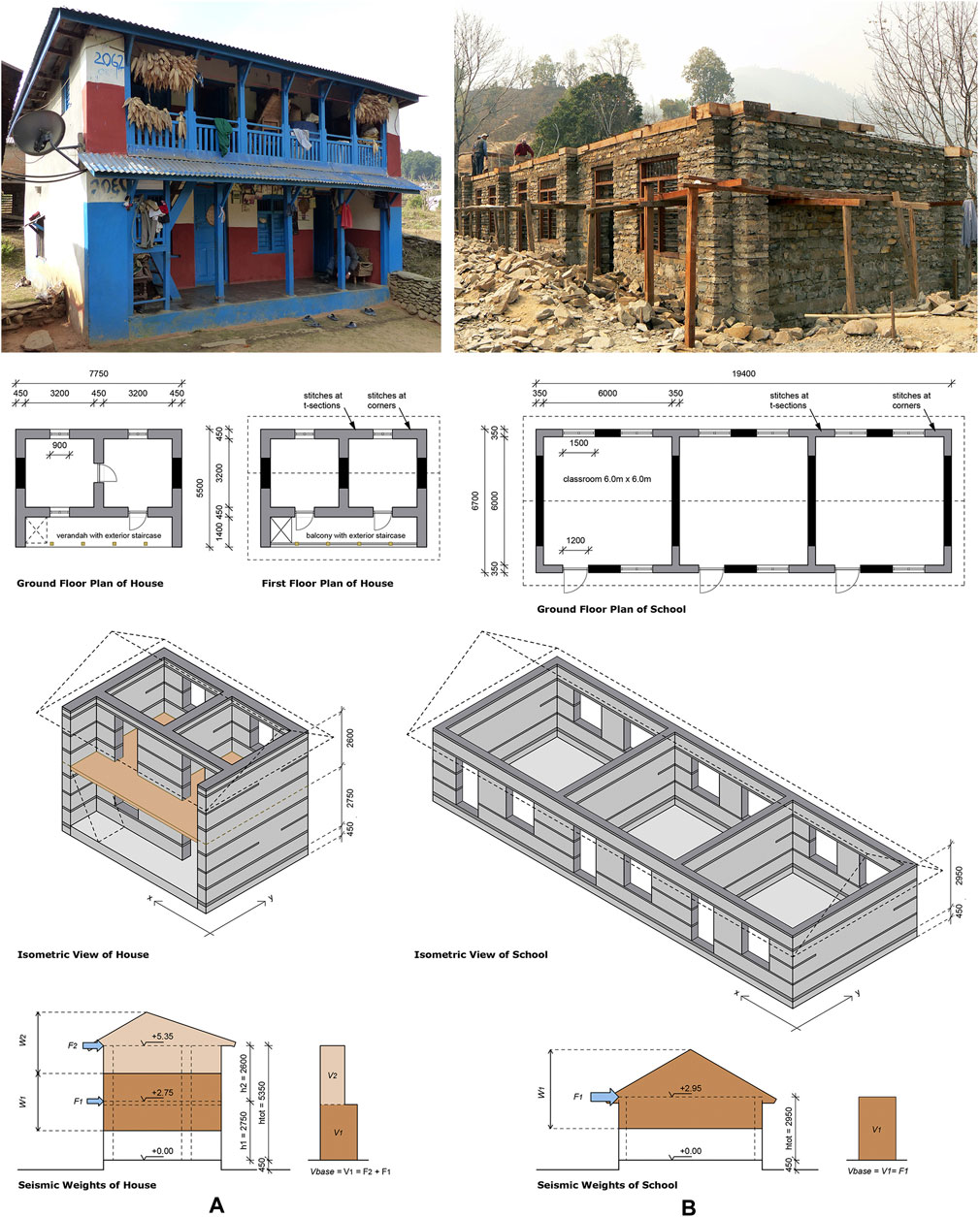
FIGURE 1. Case study designs based on typical constructions in Nepal: (A) Two-story house with verandah. (B) One-story school with three classrooms (all by courtesy of Smart Shelter Foundation).
The codes of the following countries are analyzed in further detail, and applied as literally as possible, aiming to avoid opinion and interpretation. It is important to note that these are read and analyzed in their original languages by native speaking experts; acknowledged at the end of the paper. Currently, rubble stone masonry buildings in seismic areas are only allowed in seven countries in the world, being Nepal, India, China, Tajikistan, Georgia, Iran and Croatia. For Nepal the revised seismic code of 2020 is included, even though it is not yet officially published (as of December 2020), and for China their rural seismic code is analyzed. Georgia is currently in the process of adopting Eurocode and development of a National Annex to Eurocode 8, therefore their current seismic code PN 01.01-09 (2012) is excluded. Although prohibited by their codes, three more countries where stone masonry is still abundantly practiced are added, being Pakistan (based on Uniform Building Code of 1997), Afghanistan (based on ASCE-7-2010) and Turkey (largely based on ASCE-7-2016). All codes are simply referred to by their country names, or abbreviated as follows:
Nepal, NEP-20, (NBC-105, 2020)
India, IND-16, IS-1893(pt.1):2016 (2016)
Pakistan, PAK-07, BCP-SP-07 (2007) and UBC-97, UBC-1997 (1997)
Afghanistan, AFG-12, ABC-2012 (2012)
US-based, ASC, ASC-10, ASCE/SEI-7-10 (2010) and ASC-16, ASCE/SEI 7-16 (2017)
China, CN-JGJ (rural), JGJ 161-2008 (2008) and CN-GB (national), GB 50011-2010 (2016)
Tajikistan, TAJ-18, SNiP RT 22-07-2018 (2019)
Iran, IRN-15, Standard 2800 (2015)
Turkey, TUR-18, TBDY (2018)
Europe, Eurocode 8, EC8, EN 1998-1:2004+A1 (2013)
Croatia, CRO-11 (National Annex to EC8), nHRN EN 1998-1:2011/NA (2011)
Determination of Static Loads and Seismic Weights
Seismic Behavior of the Case Study Buildings
All selected codes include clauses or checklists to determine whether a structure is classified as “regular or irregular,” for which symmetry and uniformity are important concepts. Vertical irregularity is no issue for the one-story school, and in the two-story house all walls are aligned directly on top of each other (= no discontinuity), in order to ensure clear and direct load paths to the foundation. Openings are kept small, horizontally aligned in height, and placed right above each other in both stories, with one deliberate exception in the interior wall to analyze the effects of this deviation. Further, both stories have an almost identical distribution of mass, with similar strength and lateral stiffness of the lateral-resisting elements (= no soft or weak story).
In the horizontal direction, plan regularity is achieved by an evenly distributed alignment of shear walls in both orthogonal axes, without re-entrant corners in plan or excessive perforations in the floors. Although the house plan is not entirely symmetric due to the veranda, a simplified check (following ASC-16) confirmed that it is within acceptable limits to avoid torsional irregularity. The elongated floor plan of the school falls within prescribed limits as well, where the length-to-width ratio should not exceed 3:1 as mentioned in the design codes for low-strength masonry of India (IS:13828-1993, 2018) and Nepal (NBC 202:2015, 2015). In EC8 this is maximized to 4:1, whereas IRN-15 reduces this to 2:1. EC8 further cautions against irregular plan shapes such as L-, T- and U-configurations, which need to be divided in rectangular units by means of seismic separation gaps. Some codes give maximum lengths of such volumes, ranging from 25 m (IRN-15) to 60 m in Intensity zone 8 and 45 m in zone 9 (TAJ-18). Overall, the house and the school can be classified as regular buildings. In terms of analysis, simple regular structures are generally subject to less uncertainties in the prediction of their seismic behavior, which is reflected in the choice of the method of analysis, explained further on.
In-plan torsional effects are also related to the diaphragm action of the floors and roofs, which are generally divided into flexible or rigid (or semi-rigid in PAK-07, AFG-12). By introducing stiff ceilings in the floors of the house design, and diagonal cross-bracing in the roof constructions of both house and school, these may act as semi-rigid diaphragms at best. However, since such strengthening measures are not common practice in non-engineered construction, the light wooden diaphragms are assumed to be flexible. The flexible range defines “the diaphragm stiffnesses for which the walls behave as though they are isolated elements, and an incremental diaphragm flexibility has no effect on the wall behavior” (Nakamura et al., 2017). Flexible diaphragms do not benefit from the advantages of rigid diaphragms (for instance concrete slabs), such as redistribution of horizontal seismic forces between the different lateral-resisting elements (proportional to their lateral stiffness), and increased box behavior of the structure by improving the out-of-plane stability of the walls. Light diaphragms do not increase the bending moment and shear force capacities of the walls since the added axial stresses are negligible, but they do have the advantage of not generating significant additional inertia forces, nor torsional effects.
Given all the above, the case study buildings, which are characterized by heavy stiff walls and light flexible diaphragms, behave differently from most common structures (such as frame buildings). As a main difference, most of the seismic forces are generated by the mass of the heavy stone walls, while the contribution of the light diaphragms is nearly negligible (97.5 vs. 2.5% of mass, as shown in the next section). An important difference with rigid diaphragms is that, for flexible diaphragms, the floor inertia forces are distributed to the vertical lateral-resisting shear walls in proportion to tributary areas. Further, the overall stability, prevention of out-of-plane failure and delamination of the wall wythes are enhanced by the deliberate addition of continuous reinforced concrete tie-beams at various levels, as well as by the limited plan dimensions, use of cement mortar, and inclusion of through-stones in the masonry patterns. Due to these intentional considerations, the immediate attention of this research is on ultimate strength verifications (internal forces, in-plane stiffness), which are expected to be more demanding than the serviceability ones (stress checks, displacements; to be addressed in separate future research) for these stone masonry buildings.
Total Dead Load of the Case Study Buildings
The most important factor that determines earthquake inertia forces in a building is its mass (Newton’s Second Law of Motion). Unfortunately, in rural and mountain areas the construction materials are generally heavy, such as bricks, stones and earth. For both buildings the self-weight, or total Dead Load (DL) of structural and non-structural elements, is determined according to the national codes for “Design Loads,” which mention characteristic densities of materials. The Nepalese code NBC 102:1994 (2007) refers to Indian code IS 875 (Part 1):1987 (2018). Pakistan and Afghanistan also use identical densities, but from different versions of ASC (ASCE 7-93, 1994, ASC-10). China includes densities in GB 50009-2012 (2012), Iran in NBRI-6 (2013), Turkey in TS-ISO-9194 (1997), and all European countries refer to EN 1991-1-1:2002/AC:2009 (2009). For TAJ-18, self-weights are taken from different Russian material norms, such as stone masonry (GOST 4001-13, 2019), concrete (SP 63.13330.2018, 2019) and timber (SNiP II-25-80, 1989).
For calculation of DL of the buildings, the densities for stone masonry, concretes, mortars and woods are expressed in kN/m3, and the self-weights of plywood and roofing sheets in kN/m2. Tajikistan further adds a safety factor γf to all materials for the determination of DL (and LL as well, next section). When codes give ranges of densities, an average value is taken, such as for reinforced concrete in India, or timber in China. Two scenarios are determined, being a “lower-density” version with materials of lighter weights such as sandstone and softwood, and a “higher-density” version based on granite stone masonry for the walls and hardwood for the roof, floors, doors and windows. The Indian, Iranian, Turkish and US-based codes define clear values for different types of rubble stone masonry based on stone type, whereas China makes a distinction between degrees of coarseness of the stone finishing. In Russia and Europe the values for stones and mortars are mentioned separately, and combined into stone masonry with a weight ratio of 70–30%. Further, a layer of interior cement-sand wall plaster is included as this adds significantly to the total weight of the house and school, namely +7 and +5% respectively. Densities of timbers are either taken from national codes (EN 1912:2012, 2012), publications on forestry (Arian et al., 2007; Kirchhoff and Fabian, 2010; Bhatt et al., 2016) and online databases (Orwa et al., 2009). Commonly used softwoods are pine and poplar, and for hardwoods Sal, Oak and Chestnut are included. The weight of the roofing sheets (+20% extra for overlaps) is cross-checked with actual data from Nepal for 26-gauge (= measure of thickness) corrugated sheets.
All relevant densities are collected in Table 1, which further includes the total calculated DL for both case study buildings, based on the lower-density scenario. It shows that the self-weights for the house and school are nearly identical, with a difference of less than 1% for each country. The Turkish values for sandstone and granite are the highest, resulting in the highest DL overall. In the upcoming calculations the sandstone scenario is taken as the lower limit, and the Turkish granite scenario (last column in the table) as the upper limit. Since the generation of seismic force is directly proportional to weight, such significant differences must be considered; both designs in Turkey (higher-density) are nearly 28% heavier than in China (lower-density). The influence of the other materials, such as the difference between softwood and hardwood, is almost negligible. Further, the total DL is split into portions of walls and diaphragms, which confirms that almost all mass is located in the walls, with an overall average of 97.8 vs. 2.2% in the floors and roofs in the house, 97.5–2.5% in the school, or roughly 97–3% when excluding the plinth in both; for the sandstone scenario.
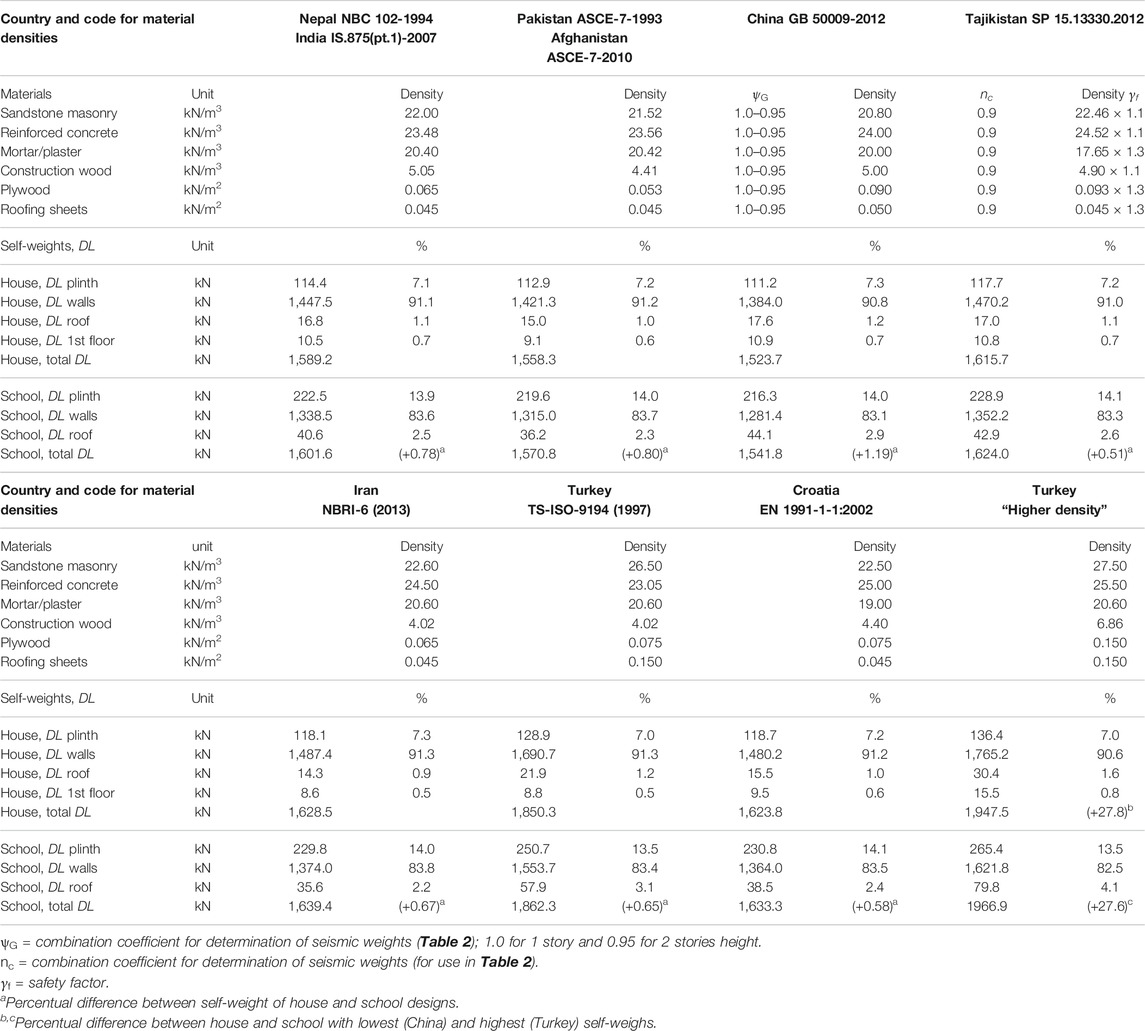
TABLE 1. Lower-density scenario of materials and distribution of Dead Loads for the house and school.
Seismic Weights of the Case Study Buildings
The total Seismic Weight (Wtot) included in base shear calculations, is usually defined as the sum of Dead Load (DL) plus portions of Live Loads (LL) and Snow Load (SL), for which combination coefficients are given in the seismic or loading codes. All seismic codes indicate that wind loads are not considered simultaneously with earthquake loads. In both buildings, the ground floor is built “on grade” meaning there is no connection between plinth and floor, thus LL is excluded as loads are directly transferred to the ground. All codes also exclude LL on (pitched) roofs for determination of Wtot, resulting in no LL whatsoever for the schools. Values for LL, called Imposed Loads in India (IS 875 (Part 2):1987, 2018), Occupancy Loads in Nepal (NBC 103:1994, 2007) or Long-term Loads in Tajikistan (SNiP RT 20-01-2012, 2016), are shown in Table 2, ranging between 1.5 and 2.0 kN/m2 on residential floors, and 2.0–4.0 kN/m2 on corridors and verandas. The Turkish values are taken from the loading code TS-498 (1997). The combination coefficients are defined as ψc in China, nc (TAJ-18, TUR-18), ψ2 in Europe (EN 1990:2002+A1, 2010), or Ccomb (remaining codes); and range between 0.2 in Iran to 0.8 in Tajikistan. Turkey and Europe divide their coefficients based on occupation, being 0.3 for residential and 0.6 for school functions.
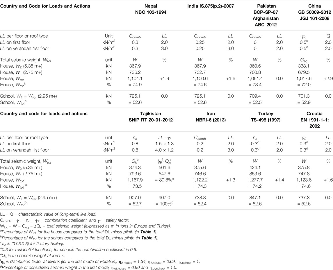
TABLE 2. Live loads and distribution of seismic weights for the house and school designs.
Regarding snow, China, Tajikistan and Turkey always include SL, whereas India, Pakistan, Afghanistan, Iran and Europe limit this to severe conditions, for instance when design snow loads exceed 1.5 kN/m2. This translates to a layer of 1.5 m of fresh snow or 75 cm of settled snow (EN 1991-1-3:2003, 2009). Although it is acknowledged that snow can add significantly to Wtot, the portion of SL is excluded as this is assumed to occur in exceptional cases only. Heavy snow is generally limited to very high altitudes which are often sparsely inhabited, where flat roofs are more common than pitched roofs due to high wind velocities, and people take care in removing heavy packs of snow as quickly as possible. The Indian code for load combinations (IS 875 (Part 5):1987, 2018) further states that “simultaneous occurrence of maximum values of wind, earthquake, imposed and snow loads is not likely.”
Table 2 further shows the calculated seismic weights for the house and school. All codes include full DL except TAJ-18, which introduces a combination coefficient nc = 0.9 (Table 1), and China ψG = 0.95 for 2 story-buildings (for both DL and LL). However, the walls in TAJ-18 are multiplied by a safety factor 1.1, so the effective reduction is just 1% (1.1·0.9 = 0.99). None of the codes add LL to the pitched roofs, whereas the increase of LL related to the DL of the house ranges between +0.9% in Iran to +2.0% in China. This minimal addition does not change the overall division of masses which remains to be roughly 98% walls vs. 2% diaphragms. To compare, a quick check of the weight implication of a rigid concrete slab (Nepalese values) resulted in an increase of nearly 18% for the house and 28% for the school, which proportionally increases the inertia forces.
The seismic weights Wi (at i-th floor level) are conventionally lumped at the top of both buildings and first-floor level of the house. Some codes specifically describe the division of weights from the mid-levels of the story heights to the respective levels above and below (NEP-20, IND-16). For the house, the relation between W2 and W1 is almost exactly 1/3-2/3 for all countries. As the plinth is tightly packed with soil it is considered as part of the ground, thus level +0.0 m starts at the top of this platform (Figure 1). The ground floor is not connected to the walls, and its loads are assumed to disappear directly into the ground. However, the bottom half of the ground floor walls is not considered in Wtot, meaning that for the house over 25% of the total DL (minus plinth) is not considered in the seismic weight, and for the school nearly 50%. The percentages in Tajikistan differ as the seismic weights are determined per each separate level (including safety factors), and then multiplied by a level distribution factor ηi. For these “simple” case study buildings, only the first mode of vibration needs to be considered (explained in the next chapter), resulting in 10% reduction of the total considered seismic weight for the house (ηtot,house = 0.90). Although the applied way of lumping masses just at floor levels (and exclusion of the plinth level) is a conventional and accepted approach for frame buildings that have a high ratio of mass located in the floors, the question rises whether this is an appropriate approach for heavy stone masonry buildings, where almost all mass is located in the walls. However, alternative approaches such as the distributed mass system and equivalent frame model are not suggested in any of the codes. Such possibly more suitable concepts will be addressed in follow-up papers, at the validation stages of the overall research.
Seismic Base Shear for Ultimate Limit State
This section analyzes and compares Equivalent Lateral Force methods and corresponding base shear formulas of selected codes, to be used for calculation of the Ultimate Limit State seismic demand of the rubble stone masonry house and school. The analyses aim to determine which seismic code or country is the most tolerant or most conservative toward this technique. In the spirit of “non-engineered seismic design,” the focus is on a simplified approach performed by hand calculations, wherever possible.
Performance Objectives and Limit States
To design and validate structures, most modern codes define seismic performance objectives and impose a form of limit states design for the verification of structural elements. Performance objectives are defined as the relation between expected seismic hazard (earthquake design level) and acceptable damage (building performance level, or limit state). Recommended design levels are for “frequent, occasional, rare and very rare earthquakes,” based on probability of exceedance during the lifetime of the building and/or recurrence interval, whereas recommended performance levels are generally divided into “fully operational, operational, life-safety and near collapse” (Vision 2000 Committee, 1995). Two important limit states are: i) Serviceability Limit State (SLS) for light but frequently occurring earthquakes with a no-damage objective. It requires that a structure remains in its elastic phase without any residual displacement after being subjected to earthquake action, and is mainly concerned with limitation of stresses and displacements; and in the case of masonry with avoidance of cracking. It is however expected that SLS-verifications are not governing in seismic design of stone masonry buildings. ii) Ultimate Limit State (ULS) for severe but less often occurring seismic events, either allowing damage or preventing collapse. The ULS-verification considers the non-linear resources of materials and relies on the strength, ductility and energy dissipation characteristics of the structural elements. For stone masonry, it mainly deals with strength design properties such as compression, tension, flexure and shear, with the basic restriction that, for each internal action, the seismic demand does not exceed the ultimate capacity.
The immediate attention of this paper is on ULS and the primary performance level of life-safety. In EC8 this is referred to as a no-collapse requirement, whereas the US-based codes (PAK-07, AFG-12, ASC) refer to comparable Strength Design procedures and define a “reliability objective” that must meet certain Strength Limit States. Pakistan and India have not (clearly) defined any objective, whereas IRN-15 relates three levels of allowable damage to the importance of the structure.
Reference Earthquake Design Level
The following reference for comparing the ULS-verification methods is taken: “The rare earthquake event” characterized by 10% probability of exceedance within 50 years of service life of the structure (10%PE50y), or a 475-year return period (RP475), such as clearly defined in NEP-20, PAK-07, CN-JGJ, IRN-15, TUR-18 and EC8. Afghanistan, following ASC-10, takes the Maximum Considered Earthquake (MCE) for 0.2s spectral response acceleration as the starting point (2%PE50y). The mapped MCE values are then scaled by two-thirds, which represents a close approximation of the life-safety design level of 10%PE50y (Leyendecker et al., 2000). IND-16 has a similar approach but defines the design earthquake at 50% of MCE. However, these seismic intensities are not based on probabilistic hazard analyses but were assigned empirically, based on engineering judgment. Therefore, it is not possible to assign a probability of occurrence to these levels (Jain, 2003; Jain and Rai, 2019). The design earthquake levels in TAJ-18 are also not based on a probabilistic approach, but on the MSK-64 intensity scale (Medvedev and Sponheuer, 1969). China has defined three “basic seismic precautionary levels,” where CN-GB takes the first no-damage requirement under frequent earthquakes (63%PE50y or RP50) as their main design earthquake level “unless stated differently”. Such is the case for stone masonry in rural code CN-JGJ, which dictates the second design level with the objective of repairable damage under “precautionary-level” earthquakes (10%PE50y or RP475). The naming of “precautionary and rare (third-level)” in China is somewhat confusing as all other countries refer to these as “rare and very rare”. All objectives (if clearly defined in the codes) and earthquake design levels are shown in Table 3.
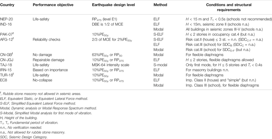
TABLE 3. Relation between performance objectives, earthquake design levels and method of analysis for Ultimate Limit State verifications of the rubble stone masonry case study buildings.
Seismic Analysis Methods
Types of seismic analysis include linear (elastic) methods such as the Equivalent Lateral Force method (ELF, static) and Modal Response Spectrum method (dynamic), as well as non-linear (inelastic) methods like the Pushover analysis (static) and Time-History procedure (dynamic). In the spirit of “non-engineered seismic design” the focus lies on the static linear procedure, which idealizes the structure as a single-degree-of-freedom system, with its total mass oscillating as one at its fundamental period of vibration. It substitutes the earthquake ground motion with external (“equivalent”) static horizontal forces that amount to the base shear force. Generally, masses are lumped at each floor level, and the story forces are used to determine the displacements and internal forces in the structure. ELF computes the maximum base shear for the seismic weight of the structures, as determined in the previous chapter.
A first major condition for application of ELF in all codes, is that buildings must be regular in both plan and elevation. For both case study buildings these conditions are met (previous chapter). Further requirements are added to Table 3, including maximum allowed heights of structures (H between 2 and 5 stories), maximum values for the Natural Period of Vibration (T ∼0.4–0.5 s), the building importance, and seismic zoning. Pakistan introduces a Simplified ELF (S-ELF) method for buildings with H ≤ 2 stories in occupancy category 4, which applies to both the house and the school design. AFG-12 also recognizes both ELF and S-ELF but relates the method of analysis to a seismic design category (SDC), as defined by different levels of design accelerations in combination with a risk category. The school (category III) qualifies for ELF in SDCB (approx. <0.13 g), whereas the house (category II) is exempt from seismic analysis in SDCA-B. Both case studies are not permitted in SDCC-F which prohibits ordinary and detailed plain masonry shear walls. EC8 has a similar approach, where the house (importance class-II) conforms to a list of requirements for material strengths, dimensions, reinforcements and minimum percentages of cross-sectional area of shear wall, and therefore can be marked as a “simple masonry structure” for which no verification is needed. The school (class-III) however requires modeling because of the flexible diaphragm. Turkey and China (CN-GB) also demand dynamic analysis for flexible diaphragms, whereas CN-JGJ allows ELF for buildings with H ≤ 2 stories regardless of the type of floor and roof. India has the strictest code by allowing ELF only for buildings with H < 15 m and T < 0.4 ms in the lowest seismic zone II (design acceleration Z/2 ≤ 0.05 g). However, their seismic code for low-strength masonry (IS:13828-1993, 2018) requires no special provisions in zone II, effectively meaning that rubble stone masonry houses (schools are prohibited in any case) must be dynamically modeled in zones III–IV (although not recommended in IV and prohibited in V). Iran on the other hand does not require any form of analysis for URM (or CM) whatsoever. Lastly, the Russian-based codes require Modal analysis (called spectral method) for all structures, where the seismic weight at each level is multiplied by a level distribution factor ηik, which takes into account the displacements at the different floor levels for different modes of vibration. However, for simple buildings (H ≤ 5 stories and Ti < 0.4 s, TAJ-18), a simplified formula (S-Modal) is given which only considers the first mode and where η1,k is directly related to the building height. In this respect the S-Modal analysis closely approximates the ELF method, with the main difference that S-Modal includes a reduced portion of the total seismic weight.
Some caution is observed. As ELF computes the maximum base shear, this method tends to overestimate the base shear for short-period buildings due to the inclusion of the full seismic weight, as opposed to the response spectrum modal analysis which combines the effective weights of all modes, of which the first-mode effective weight typically amounts to 60–80% of the total seismic weight (Villaverde, 2009). For modal analyses, most codes dictate minimum 85–90% of activated mass, or demand validation of at least three modes (TAJ-18, IRN-15). For masonry, Priestley et al. (2007) recommend the inclusion of 90% of effective (or equivalent) seismic weight, which is in line with the S-Modal method in Tajikistan, where 89.8% of the seismic weight is considered for the house (Table 2). Since the generation of earthquake inertia forces is proportional to mass, risk of overestimation will be of major influence on the heavy stone masonry buildings.
Base Shear Formulas for the ELF Method
Given the simplicity and regularity of the two case study buildings, it is assumed that both house and school designs qualify for either ELF or S-ELF (or comparable approaches) in all countries. Base shear is the maximum lateral force, expected to occur at the base of a structure due to seismic motions. All codes present the base shear formulas in terms of a seismic acceleration coefficient, applied in the center of mass of the structure and defined as a fraction of the gravity acceleration (g), to be multiplied by the total seismic weight of the structure (Wtot). Most formulas are structured (or can be restructured) similarly and express the base shear as a function of the spectral acceleration, to be reduced by a structural behavior factor. The spectral acceleration results from the peak ground acceleration at bedrock (PGAbedrock), that is first amplified by the overlaying soil conditions (peak ground acceleration at surface level = PGAsurface), and then further modified by the structure in relation to its fundamental period of vibration T. The spectral acceleration is plotted in an elastic (unreduced) response spectrum as a function of T and for a given site profile; in the upcoming comparisons rock is taken as the reference soil. The elastic response spectrum is then reduced by the structural behavior factor that in general accounts for the inherent inelastic properties of the lateral-resisting structural system such as ductility, overstrength and energy dissipation, although for stone masonry these are expected to be minimal. Most codes refer to this as the design response spectrum, but to avoid confusion of terminology, this paper refers to “reduced (inelastic) response spectrum” (vs. unreduced (elastic) response spectrum). The base shear may be further increased due to the importance of the structure. This leads to the following conceptual representation of base shear for ULS-verifications:
where
(PGAbedrock·soil)·spectral amplification = spectral acceleration
and PGA = PGAbedrock
or PGA = (PGAbedrock·soil) = PGAsurface
depending on how each code provides the seismic hazard.
All original base shear formulas and base shear coefficients for both ELF and S-ELF are shown in the first column of Table 4, which are then combined and conceptually rewritten in the second column. The last column shows additional requirements or restrictions, such as minimum and maximum limitations of the base shear. Since S-Modal considers only the first mode, it qualifies for the conceptual rewrite with the notion that the seismic weight (Qtot) is not fully included (for the house), by introducing the combined effect with the level distribution factors (ηk·Qk) as an additional constant (ηtot,house = 0.90 and ηtot,school = 1.0, Table 2). Although the US-based formula of AFG-12 is not related to PGA (by using the full spectral acceleration based on different parameters), it can still be rewritten in such way that it very closely approximates the life-safety design level of 10%PE50y, as explained previously. The spectral acceleration in TUR-18 (which largely follows ASC-16) also matches this approximation. However, this formula is the only one that cannot be rewritten into the conceptual format, as it does not have a constant-ordinate plateau (between TA and TB) in the reduced response spectrum, since the Turkish seismic load reduction factor Ra(T) considers a linear dependence on variable T/TB toward TB. The Chinese codes differ by combining all the functions related to seismic hazard and structural behavior into one single coefficient α, which are lower for SLS-verifications (CN-GB) and higher for ULS-verifications (CN-JGJ, included in Table 4).
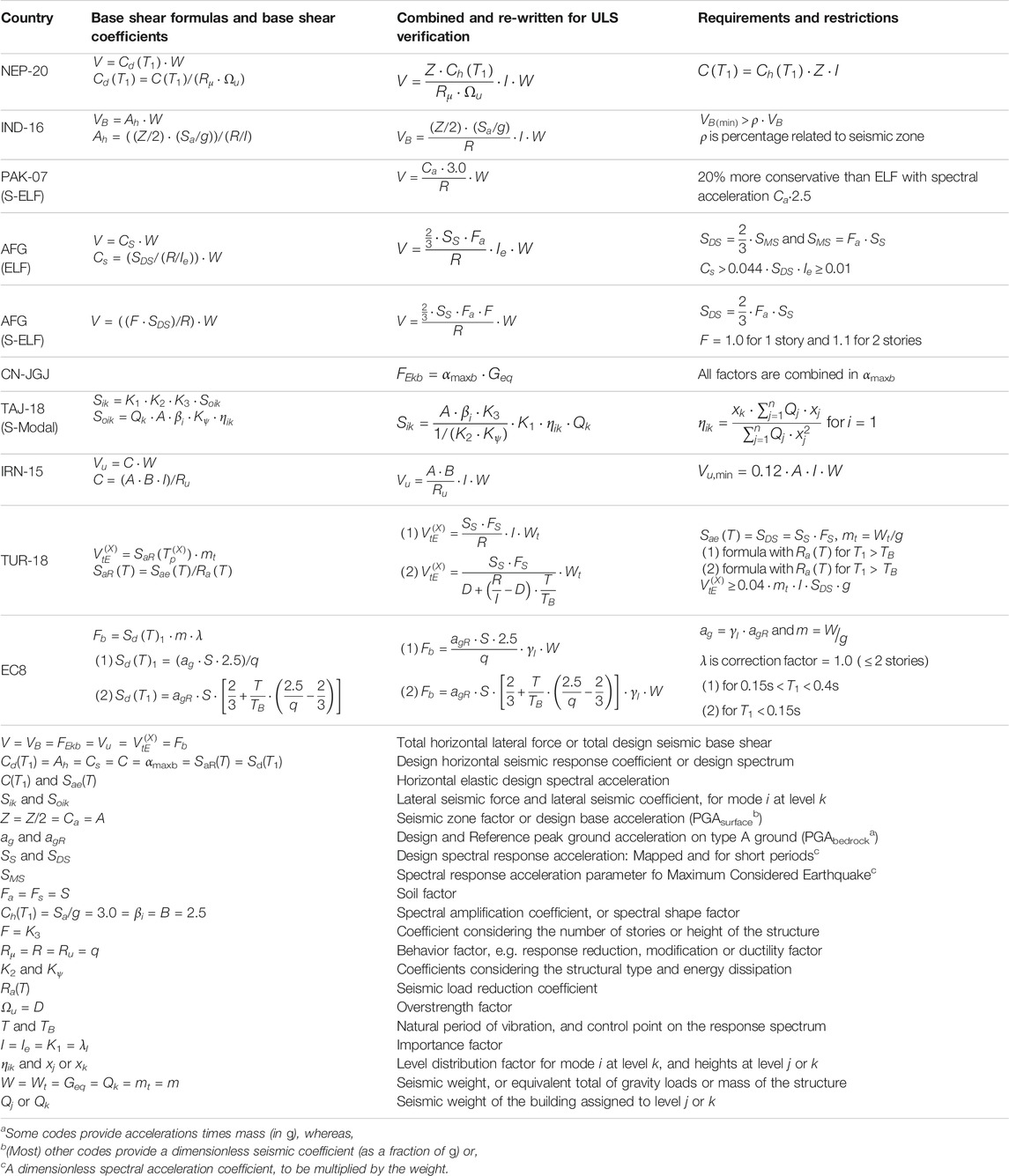
TABLE 4. Conceptual base shear formulas combined with seismic coefficients, for ULS-verification.
All differences as described above are further explained in the next sections, which compare each of the base shear factors separately. For each formula it is aimed to extract the design peak ground acceleration, simply referred to as PGA, at either bedrock level (PGAbedrock) or ground surface level (PGAsurface), depending on how this design value is provided by the codes. By doing so, it is possible to compare the effects on a particular structure due to the ground conditions and structural characteristics as dictated by each national code, for any given hazard at site. All relevant values and coefficients that are used for the comparisons in the next sections, are added to Table 7.
Soil Conditions
Since local soil conditions have a significant influence on the PGA and shape of the response spectra (Villaverde, 2009), first the reference soil type is determined. The codes distinguish several parameters for soil classification, of which the “average shear-wave velocity in the upper 30 m (vs,30 in m/s)” is most recommended (PAK-07, CN-GB, IRN-15, TUR-18, EC8). Nepal and India distinguish 4 soil classes by using different parameters. Nepal expresses hard rock and stiff soils (type A) in terms of “unconfined compressive strength (in kPa)” and divides soft soils (type C) by “standard penetration test values (NSPT in blows/30 cm)” or by “representative undrained shear strength (su in kPa),” whereas IND-16 defines the bearing capacity of all subsoils in terms of NSPT. However, these distinctions are less relevant, as the response spectra for short-period buildings in Nepal and India are similar for soil types A-C, whereas construction on weak soils (type D) “should be avoided”. Soil type C roughly resembles soil profile SD (PAK-07), class D and ZD (AFG-12, TUR-18), site category III (CN-GB, IRN-15, TAJ-18) and ground type C (EC8) with vs,30 around 150–180m/s. Depending on seismic zone or structural typology, the PGAbedrock values are amplified by a separate soil adjustment factor ranging from S = 1.15 (EC8) to as high as Fa = 1.6 (AFG), whereas the soil effects in Nepal, India, Tajikistan and Iran are directly combined into PGAsurface, and in China into PGA.
As the limits of softer and weaker soils cannot be fully aligned, rock soil with vs,30 around 750–800m/s is taken as the reference condition for fair comparison of the base shears. These are types A (NEP-16, IND-16, EC8), category I0 (CN-GB), category I (IRN-15, TAJ-18), soil profile SB (PAK-07) and class B (AFG-12), which all have a soil factor of 1.0. However, following the latest revision in ASC-16, the Turkish soil factor Fs for class ZB is reduced to 0.9. Tajikistan relates the soil effects to the design seismic intensity as given for different seismic zones (without an additional soil factor), in China the soil effects are adjusted within the design seismic coefficient α, and in Iran the soil factor S is directly linked to the spectral amplification; all further explained in the next sections. Lastly, it is realized that rocky ground is a best-case scenario, but the fact that most rubble stone masonry takes place in mountainous areas, does not necessarily mean that all sites have favorable soil conditions. For instance, Kathmandu Valley is highly susceptible to basin effects, site amplification and liquefaction potential (Tallett-Williams et al., 2016). Therefore, local soil conditions must always be considered on a case-to-case basis.
Design Peak Ground Acceleration
The intensity of expected ground motion at a given site (site hazard) is expressed in terms of a design peak ground acceleration (PGA), which in most codes is either defined as PGAbedrock or PGAsurface, and in US-based codes as the full spectral acceleration. The earthquake design levels are stipulated by the codes either through set values of PGA that correspond to designated seismic zonation, by interpolation of seismic hazard contour maps, or by site-specific tabulation of coordinates. This section compares the PGA values for ULS-verification on rock soil for each country. All seismic zones and corresponding PGA are shown in Table 5, which is further combined with the required verification methods (and restrictions) for both the house and school designs (Table 3). NEP-20 assigns a seismic zoning factor (Z) to selected main locations, or else Z must be determined by approximate interpolation between the contour lines of the seismic zoning map. IND-16, PAK-07 and IRN-15 directly assign a design coefficient (Z/2, Ca and A, respectively) to each seismic zone as drawn on their zonation maps. Pakistan adds a near-source factor (Na = 1.1) for all sites, but only in the highest seismic zone 4. In most Russian-based codes the PGA values are assigned to seismic intensity zones where soil category II is taken as the reference. For instance, intensity zone 9 represents A = 0.40 g (TAJ-18). However, on rock soil (category I) it is permitted to use the design values of one intensity level less, so that zone 9 becomes zone 8 with A = 0.20 g. Effectively it means that on rock soil, the base shear is reduced by half.
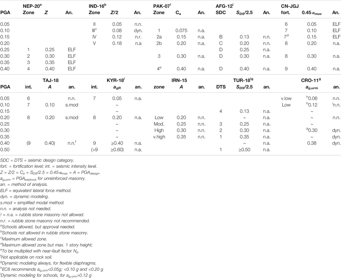
TABLE 5. Relation between seismic zones, design peak ground accelerations and allowed methods of analysis for houses and schools on rock soil.
AFG-12 (following ASC-10) maps the complete short-period spectral acceleration for the very rare earthquake event (SS ·Fa at 2%PE50y) on rock soil (Fa = 1.0), which needs to be reduced to the design level (SDS = 2/3·SS at ∼10%PE50y). Set limitations of the design values correspond with an SDC which defines the method of analysis. To transform these set values into representative PGA levels (although not utilized as such in the US-based approach), they are to be divided by the spectral amplification (SDS/2.5), which is a close and acceptable approximation for initial design purposes (Leyendecker et al., 2000). TUR-18 also accepts PGA = SDS/2.5 and has adopted a system of site-specific hazard coordinates, which includes spectral acceleration (as well as PGA) values for 10%PE50y. The Chinese seismic zonation parameter map (GB 18306-2015, 2016) assigns a level of “seismic fortification intensity” (6-9) to all administrative districts based on local seismic hazard, site profiles and near-fault conditions. This intensity is coupled with three sets of seismic coefficients (αmax), of which the rural code CN-JGJ requires the precautionary (second) level (10%PE50y). These values are 2.8 times higher than for frequent earthquakes in CN-GB (63%PE50y = SLS) and can be easily translated to PGA by dividing the maximum acceleration coefficient with the spectral amplification (=0.45·αmaxb, see next sections). EC8 recommends “unreinforced masonry (URM) that satisfies prescribed provisions” only in areas with PGAbedrock = ag,urm ≤0.20 g. However, CRO-11 has set no limitation, but requires dynamic modeling for schools (always) and houses for ag,urm>0.30 g.
To make any further differences visual, seismic hazard maps for the rare earthquake event on rock soil are combined for South and Central Asia (Figures 2A,B), and for the Caucasus and Middle East (Figures 2C,D). The 0.2 s spectral acceleration map in AFG-12 is taken from Boyd et al. (2007), which also contains the 10%PE50y hazard map as included here, although the report notes that the hazard values are relatively uncertain due to missing information. The preliminary map for Bhutan (10%PE50y, Goda et al., 2019) highlights the relatively low design values in India compared to Nepal, Bhutan and Pakistan. However, the Chinese PGA values (separate map for 10%PE50y in GB 18306-2015, 2016) on the other side of the Himalayan range are more in line with the Indian values of 0.12–0.18 g bordering Kashmir. In Tajikistan the maximum design values are also relatively low, as these are halved on rock soil. This differs highly with the seismic map of Kyrgyzstan (SN KR 20-02:2018, 2018), which on rock soil (S = 1.0) contains values >0.60 g (added to Table 5). For the same reason, Iranian values are much higher around the borders with Turkmenistan (SNT 2.01.08-99, 2000). The halved acceleration values in Georgia (based on MSK-64, PN 01.01-09, 2012) bordering the Greater Caucasus Range match closely with the halved values on the Russian map OCR-2015-A (10%PE50y, SP 14.13330.2018, 2018), bearing in mind that for school buildings Russia dictates a stricter map (5%PE50y, OCR-2015-B). On the other borders larger differences are noted between Georgia, Azerbaijan (MSK-64, soil factor Kq = 0.7, AzDTN 2.3-1, 2014) and Armenia (10%PE50y, K0 = 0.8, RABC 20.04, 2020). Turkey is no longer subdivided in seismic zones but has adopted a system of site-specific hazard coordinates, of which the map in Figure 2D is a representation of the Turkish gradient map (10%PE50y, Decree BKK-2018/11275, 2018). Lastly, EC8 does not contain hazard maps as these must be provided by the partnering countries in their national annexes.
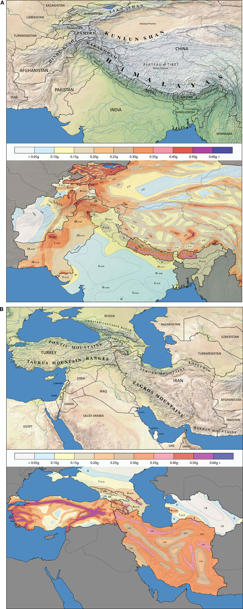
FIGURE 2. (A) Mountain ranges of South and Central Asia (original source: Natural raster + vector map) and (B) Effective design peak ground acceleration values on rock soil in these regions. (C) Mountain ranges of the Caucasus and the Middle East (original source: Natural Earth raster + vector map) and (D) Effective design peak ground acceleration values on rock soil in these regions.
Both table and map show that India uses much lower design values than its neighboring countries, where Z/2 = 0.18 g for the highest zone V is still lower than the lowest zone 1 in Nepal at Z = 0.25 g. The map further shows a relative lack of detailed zoning in India; both these concerns have been expressed in several papers over the years, such as Bhatia et al. (1999), Ghosh et al. (2012). Stone masonry is still practiced in the Northeastern regions (NE, fully assigned to zone V) and Northwestern regions (NW, zones V-IV; the latter with Z/2 = 0.12 g). Recent probabilistic seismic hazard analyses (PSHA) in the NE present PGA values (10%PE50y, zone V) ranging between 0.27 and 0.49 g for various locations in Assam (Bahuguna and Sil, 2018) and 0.18–0.60 g in Manipur (Pallav et al., 2012). In zone IV values reach as high as 0.71 g near Darjeeling (Maiti et al., 2016), whereas Das et al. (2016) estimate values not higher than 0.32 g anywhere in these regions. PSHA in the NW results in PGA around 0.6–0.75 g in the states of Uttarakhand, Himachal Pradesh and Kashmir (Mahajan et al., 2010), opposed to Rout et al. (2015) in which no value exceeds 0.36 g for the same locations. Overall, large differences are observed between these studies, but they have one thing in common: All values of PGA are significantly higher than the design value of Z/2 = 0.18 g in the Indian code. On the other hand, it must be noted that these low values are adjusted by introducing a relatively high seismic load combination factor of 1.5, making the seismic effects in India among the highest of all countries (explained further on). High variations are also seen between studies for all other countries (for instance around the borders of Tibet, Rahman et al., 2017), which indicates a substantial uncertainty in hazard estimation. Differences are caused by the many parameters that are required to develop hazard maps, which introduce a high range of assumptions about earthquake source locations, recurrences and magnitudes, for which detailed historical data are often lacking or incomplete in these regions (Stein et al., 2018).
Natural Period of Vibration
The spectral acceleration on a structure mainly depends on its fundamental (or natural) period of vibration T1 (in seconds). Main parameters affecting T1 are the weight and height of the building, as well as the stiffness of the lateral-resisting elements in relation to their distribution in plan and elevation within the structure. Generally, the taller the building, the longer its T1; the heavier the building, the longer its T1; and the stiffer the building, the shorter its T1. For stiff single-story buildings T1 is expected to be around 0.05s (Charleson, 2008). Most seismic codes provide empirical formulas to determine the characteristic period T1 along each main direction of the building. Methods that are based on determination of lateral elastic displacements, requiring a Finite Element model, or following the Rayleigh method, are left out of this analysis as these cannot be performed by simplified hand calculations. For S-ELF in PAK-07 it is not required to calculate T1, and TAJ-18 does not include any formula.
The most generally used approximate formula T1= Ct·H3/4 is applicable to all structural systems, provided the building height does not exceed 40 m (EC8) or 120ft (ASC). It applies to both principal directions of the building and mainly depends on its height H, which is multiplied by a numerical coefficient Ct based on structural type; around 0.05 for masonry shear walls. The definition of height as measured from the base is different in the codes. IND-16 and EC8 take the top of the structure, whereas AFG-12, ASC and IRN-15 use the average height of the pitched roof. NEP-20, PAK-07 (ELF) and TUR-18 limit the height to the uppermost main portion of the structure (top of walls), which seems most appropriate for the case study buildings where 98% of all mass is in the walls. For URM, Priestley et al. (2007) recommend a reduced height of 0.8·Hn for multi-story buildings (Hn= total height as defined in EC8). The influence of height becomes apparent in the calculated values for T1 in Table 6A. It is further noted that NEP-20 makes the period estimation value larger by introducing an extra multiplier of 1.25.
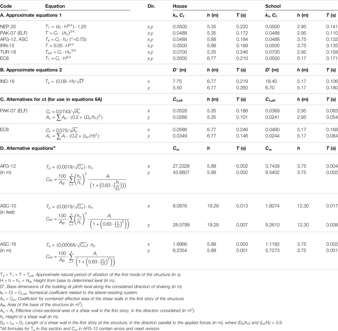
TABLE 6. Comparison of equations and calculations of Natural Periods of Vibration for the case study buildings.
IND-16 determines T1 for each base dimension along the considered direction of earthquake shaking. Longer and stiffer walls produce shorter periods, and as the full base dimensions are used, this results in lower values of T1 in the x-direction, Table 6B. However, this equation does not consider the openings in the walls, whereas in both case study buildings the percentage of shear walls in the transverse y-direction is dominant. PAK-07 (ELF) and EC8 introduce alternative equations to calculate Ct in relation to the combined effective area of all individual shear walls in the first story of the structure. The calculated values for T1 show that the x-direction produces the longer period, and therefore seem most realistic for rubble stone masonry buildings, Table 6C. TUR-18 introduces a similar equation, but only applicable for concrete shear walls. The alternative method in AFG-12, ASC-10 and (slightly adjusted in) ASC-16 is developed by Goel and Chopra (1998), but for tall buildings with concrete shear walls. For low-rise-heavy masonry buildings however, the equations produce too low values and contain errors, Table 6D. AFG has incorrectly copied the formula by omitting a factor ^2 and mixing an imperial-based coefficient within their metric-based code. Furthermore, values for T1 in the metric system are 10x lower than those in feet. These observations were sent to the responsible committee of ASCE whom confirmed that the equations need revision (Charney, 2019).
Spectral Amplification
The shape of the response spectrum (actually pseudo-acceleration response spectrum but there is no significant difference for low values of damping) shows an idealization of how the natural period of vibration and damping of a building affect its response to earthquake ground motions, in terms of the maximum amplification of PGAsurface. The shape is illustrated as 4 branches of which only the first two segments are of interest for the case study buildings. The short-period response, starting with the anchor point (PGA) and the linearly increasing spectral acceleration, is followed by the constant spectral acceleration plateau. Figure 3 shows the first two branches of the elastic (unreduced) response spectra for rock soil with 5% viscous damping, for all selected countries. The conventional damping ratio ζ = 5% is generally accepted for all types of masonry, while the structural behavior factor (next section) in the codes is usually calibrated for 5% viscous damping. However, this may need future validation as only limited data is available on viscous damping ratios for stone masonry with lime-based or mud mortars, with high variation in outcomes ranging between 2 and 9% (Mazzon et al. (2009); Elmenshawi et al. (2010)), whereas no data was found for stone masonry with cement mortar.
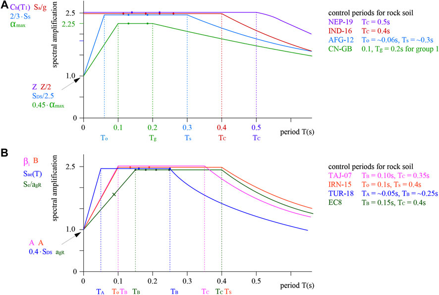
FIGURE 3. Linear increasing spectral acceleration and constant spectral acceleration plateau of elastic response spectra for rock soil with 5% viscous damping, according to the seismic codes of (A) Nepal, India, Afghanistan, China, and (B) Tajikistan, Iran, Turkey, Croatia.
The corners of the plateau are usually fixed and given by the codes, where the first control point for the linear acceleration ranges between an average interpolated value of 0.06s (AFG-12) and 0.15s (EC8), whereas the second control point ranges between 0.2 s (CN-GB) and 0.5 s (NEP-20). This low value in China, resulting in a response spectrum with a very short plateau, may only occur at locations very near to faults (named “design seismic group 1”). The control points for the US-based and Turkish codes are not fixed and must be determined on a case-to-case basis as a relation between the ordinates at long and short periods (0.2·SD1/SDS and SD1/SDS) and depending on soil type. Figure 3 shows the averages of 25 randomly calculated values as taken from the Afghan (ABC-12) and Turkish (Decree BKK-2018/11275, 2018) hazard maps. NEP-20 and IND-16 have normalized the full spectral acceleration to the maximum plateau value. Iran includes two response spectra, one for low-to-moderate, and the other for high-to-very high seismic levels (shown in this paper).
The calculated values for T1 are added to Figure 3, showing that for both directions of the buildings, almost all ordinates fall within the constant plateau. This means that the spectral amplification is maximum (and most conservative) with a value of 2.5 for all countries except China at 1/0.45 = 2.222. No spectrum is included for S-ELF (PAK-07), other than the introduction of a more conservative shape factor (Ca·3.0 in the numerator). AFG-12 makes S-ELF more conservative by introducing an extra multiplier (F) related to the number of floors above grade. TAJ-18 also includes a coefficient related to the building height, K3 = 1.0 for ≤5 stories. As China defines the same height as AFG-12 (halfway pitched roof), the same values for T1 are assumed on the Chinese spectrum (CN-GB). In Iran the amplification is called “building behavior factor B”, determined as B=S+1 = 2.5 since the soil parameter S is always 1.5 on the plateau for rock soil. Although T1 is not calculated for Tajikistan, it is assumed it falls on the plateau with maximum amplification β1 = 2.5. Only once T1 falls outside the plateau, for the y-direction of the school in EC8 (Table 6C), resulting in a reduced amplification.
As a point of attention, Kwon and Kim (2010) note that the approximate formulas (Table 6A) overestimate the natural period. For low-rise masonry buildings this may lead to more conservative seismic design, as values that are approximated on the constant plateau may realistically fall within the first linear branch of the response spectrum. They further note that Ct for shear walls has not been recalibrated since the 1990’s and propose a value reduced by 25%. However, a quick check of the empirical calculations with such adjusted value (Ct = 0.375) shows no difference in the outcomes.
Structural Behavior Factor
The structural behavior factor allows for a reduction of the elastic spectral acceleration, by introducing non-linear (inelastic) mechanisms inherent to the structural typology and materials of the building, such as yielding, ductility, overstrength and energy dissipation properties. Therefore, codes make a clear distinction between the elastic unreduced response (requiring no damage) and the reduced design spectrum (allowing acceptable damage but no collapse, usually adopted for ULS).
Generally, the inelastic range for stone masonry is expected to be very limited due to the relative brittleness of the mortar. However, good quality stone masonry possesses substantial displacement and energy dissipation capacity, as well as exhibits large non-linear deformation capacity with moderate damage levels (Tomazevic and Lutman, 2007; Vasconcelos and Lourenço, 2009). This can be further enhanced by an interlocking masonry pattern with strong mortar, and by inclusion of continuous horizontal bands for improved box behavior. Although limited test data is available for these effects on stone masonry, a behavior factor around 1.8–2.0 seems achievable (Benedetti et al., 1998; Ali et al., 2013), which is in line with the recommendations in most codes. As with many segments in this paper, also this important parameter needs further validation as it highly influences the total base shear.
Several codes have included a specific behavior factor for the typology of nominally reinforced shear wall masonry with horizontal bands, usually taken as R = 2.0 (IND-16, AFG-12). NEP-20 specifies a ductility factor Rμ = 2.0 for NRM with both bands and vertical steel rods, to be multiplied by an overstrength factor Ωu = 1.2. Without vertical rods it is assumed that Rμ·Ωu = 2.0, similar to India, although in their latest National Building code, India introduces a minimum requirement of reinforcements in URM that equals R = 2.5 and restricts its use to seismic zones II and III only. However, this national code itself indicates that “it is non-statutory in nature” (IS:SP7-2016, 2016). EC8 recommends values for q between 1.5 and 2.5, which Croatia has set at q = 2.0. Iran provides no R-factor since verifications are not needed for NRM, therefore R = 2.0 is assumed. Also deviations from the general approach of R = 2.0 are observed. For reasons not explained, PAK-07 (following UBC-97) uses a very high factor R = 4.5 for masonry bearing walls. China does not include a separate behavior factor, as they dictate SLS-verification as their primary objective level, which is related to fully elastic behavior. For ULS-verifications China introduces a different set of seismic coefficients with higher accelerations values (2.8 times higher). TAJ-18 reduces the spectrum with coefficients that considers the structural typology (K2 = 1.45 for masonry) and energy dissipation (Kψ = 1.0), amounting to a total reduction of 1/(K2·Kψ) = 0.69. Turkey mostly deviates, as their seismic load reduction coefficient Ra(T) includes a variable T/TB, resulting in a linear increasing amplification toward the second control point TB, as opposed to a constant plateau in all other codes. For this reason, the bottom of the denominator cannot be rewritten into the conceptual formula; base shear must be calculated on a case-to-case basis for each ordinate on the seismic hazard map.
Importance Factor
A last modification of the lateral loads is introduced by the importance of the building, representing different risk levels based on function and occupancy. All codes assign a factor 1.0 to ordinary (residential) buildings, and a higher factor between 1.2 and 1.5 to schools, as these pose a larger risk due to higher occupancy. They should also remain operational after a disaster, for instance after the 2015 Gorkha Earthquake, the schools of SSF acted as first-aid posts and temporary shelter. PAK-07 however makes a distinction between primary-and-secondary schools (group E-1 with 50–300 students) and higher educational buildings (group A), therefore both the house and three-classroom school are assigned to occupancy category 4 with I = 1.0. It is further noted that S-ELF (PAK-07, AFG-12) has no importance factor in its formula. China (GB 50223-2008, 2008) approaches the importance differently, by assigning importance categories to buildings (house = B, school = C). First the design coefficient is determined based on performance objectives (earthquake level) and site conditions (fortification intensity level). The same coefficient is used for both buildings, but the design requirements for the school must meet those of one intensity level higher, which are stricter in terms of height and overall dimensions. TAJ-18 deviates largely with importance factor K1 = 0.25 for houses and a 40% increase to K1 = 0.35 for schools. TUR-18 defines building classes based on importance (house = BSK-3, school = BSK-1), which then are further related to maximum allowed height classes (BYS) and types of analysis. For URM, houses can only be built in BYS-8 (HN<10.5 m and SDS<0.50) and schools are not allowed for “structural systems with limited ductility”. EC8 has coupled the importance factor γIdirectly to the reference PGA for soil type A (ag = γI . agR) and recommends γI = 1.2 for schools.
Comparison of Base Shear
To compare the base shear as calculated by the ELF method (or similar), all necessary code-specified values are added to Table 7, while expressing the formulas as follows: “Base Shear = PGA·CRS·W”. The coefficient CRS represents an “amplification factor specifically for low-ductile rubble stone masonry buildings,” as a product of the maximum amplification of PGA, divided by the structural behavior of the building. By extracting the design PGA and assuming that the seismic weight is constant, the implications for the base shear according to each national code can be easily compared for any given seismic hazard. The table separates between houses (Table 7A) and schools (Table 7B) by means of the importance factor, resulting in coefficients CRS,H and CRS,S.
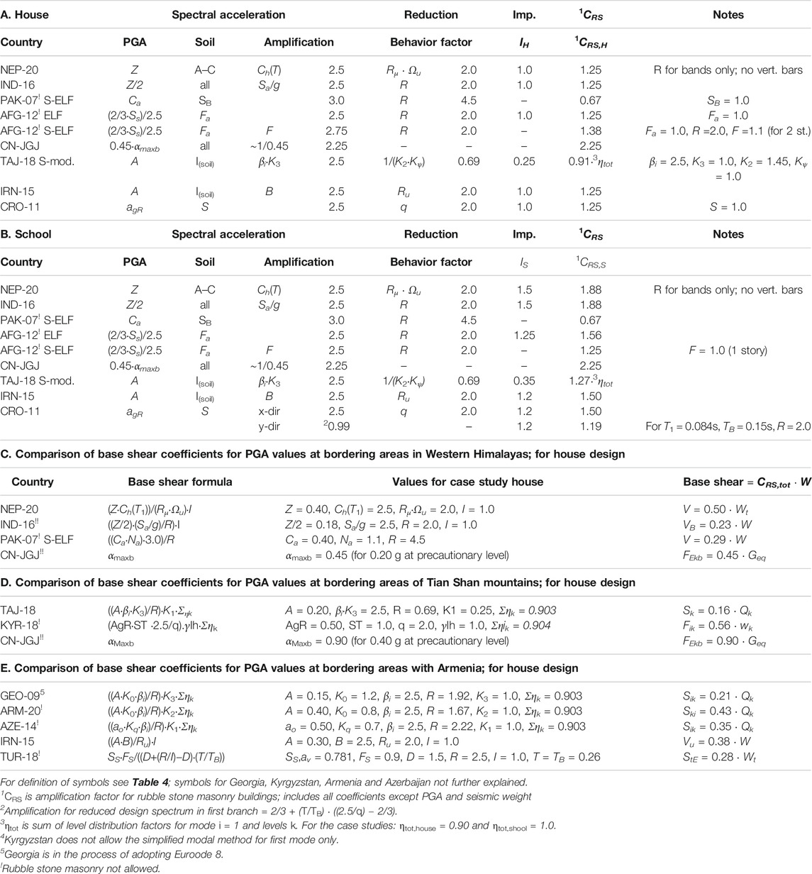
TABLE 7. Comparison of conceptual base shear formulas on rock soil for rubble stone masonry houses and schools.
For houses, it shows that the base shears in NEP-20, IND-16, AFG-12 (ELF), IRN-15 and CRO-11 are equal, and comparable for AFG-12 (S-ELF). Pakistan is roughly two times more tolerant compared to its neighboring countries, mainly caused by the high value of the behavior factor R = 4.5. In their highest seismic zone 4 (only), CRS must be multiplied with a near-fault factor Na = 1.1. In Tajikistan, CRS is also significantly lower and for the house must be further reduced by 10%, due to the partial inclusion of seismic weight (ηtot,house= 0,90). CN-JGJ on the other hand is nearly two times more conservative than its neighbors, although the design seismic coefficient αmaxb = 0.9 for the highest seismic zone (0.40 g at precautionary level), seldom needs to be applied (Figure 2B). For schools, variation between the codes is wider due to the different values for Importance factor I. Usually, CRS,S is higher than CRS,H (NEP-20, IND-16, TAJ-18, IRN-15). PAK-07 and CN-JGJ however make no difference between houses and schools (<300 students). In AFG-12 the difference between ELF and S-ELF is 10% higher for the house due to factor FH = 1.1 (2 stories) versus. FS = 1.0 for the school (1 story). This results in lower base shear for schools in Afghanistan, which is contrary to all other codes where buildings of higher importance demand a higher design force. In CRO-11 the base shear is reduced for the y-direction of the school, as T1 falls on the first branch of the response spectrum (Figure 3), for which a different formula applies.
Further, the differences are analyzed when multiplying CRS with PGA values of directly bordering areas, as mapped in Figures 2A–D. In the Western Himalayas, the highest Indian value 0.18 g connects with 0.20 g in China (Tibet) and 0.40 in Nepal and Pakistan. Still, base shear between India and Pakistan is comparable, while it doubles in China and Nepal (Table 7C). Differences around the Tian Shan mountains are much larger, as base shear is nearly 6x higher in China compared to Tajikistan (Table 7D), whereas the values bordering Armenia (except with Georgia) are more similar despite the high variation of design accelerations (Table 7E). For Turkey calculations can only be made on a case-to-case basis, thus an average value Ss for 25 regional coordinates was determined. All comparisons together give a good indication that in terms of base shear alone, Pakistan and Tajikistan are most tolerant, and China is most conservative toward rubble stone masonry. However, to complete the analyses, the distribution of forces and load combinations must also be considered.
Calculation Examples of Base Shear and Distribution of Loads
To finalize the seismic demand of the case study buildings, this chapter calculates and analyzes the base shears, distribution of lateral forces over the floors, and redistribution of the loads over the individual masonry panels. A medium earthquake level of PGA = 0.2 g is chosen, which is allowed in Iran and Croatia, and in line with the upper limit for rubble stone buildings in Tajikistan and India (0.18g, although rubble stone is not allowed). This is however higher than permitted in China (≤0.15 g), but lower than in Nepal where PGA values start at 0.25 g.
Base Shear and Distribution of Story Shears
The first step is to calculate the base shear for 0.2 g (or SDS = 0.50) with the formulas for each country of Table 4, the coefficients CRS of Table 7, and the seismic weights of Table 2. This results in the base shears presented in Table 9, confirming that Pakistan is most tolerant and China most conservative with regards to total base shear. For the house, the average of all 9 countries closely matches Vbase in Nepal, which therefore is taken as the reference country, whereas the percentual difference between the other countries is shown in the third column. The base shears are vertically distributed over the top level (F2) and first floor level (F1) of the house, with the distribution formulas of Table 8A. In Tajikistan this sequence is reversed; first the horizontal lateral loads are calculated for each floor level separately with consideration of the level distribution factor ηik, which then amount to the total base shear. The values of F2 and F1 are also added to Table 9, showing an almost even division for all countries due to a triangular distribution of the story shears. The only exception is India, which introduces a parabolic distribution for all buildings regardless of their height. Some countries have included an extra force at the top in their formula, which for low-rise buildings can be ignored.
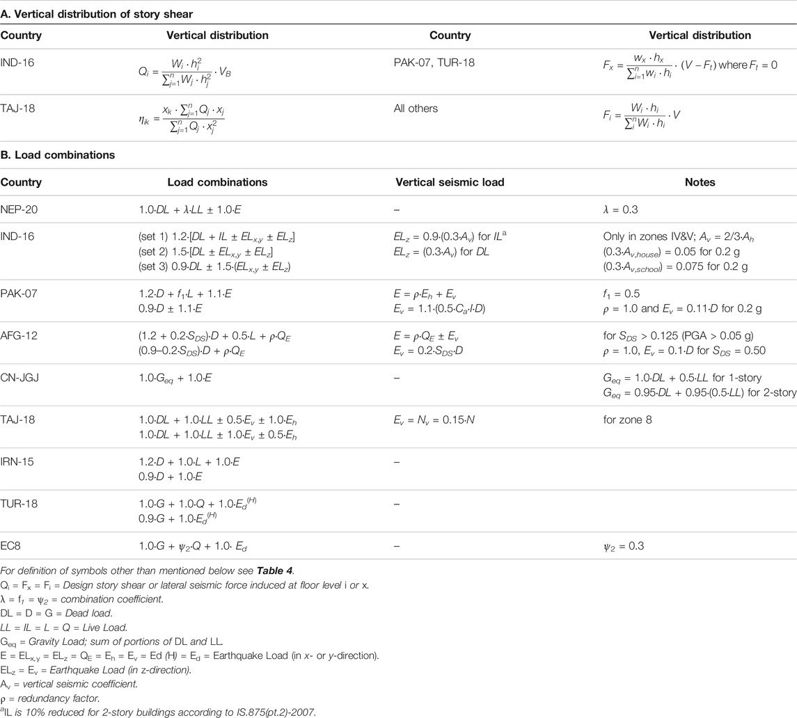
TABLE 8. Vertical distribution of story shear, load combinations and vertical seismic loads.
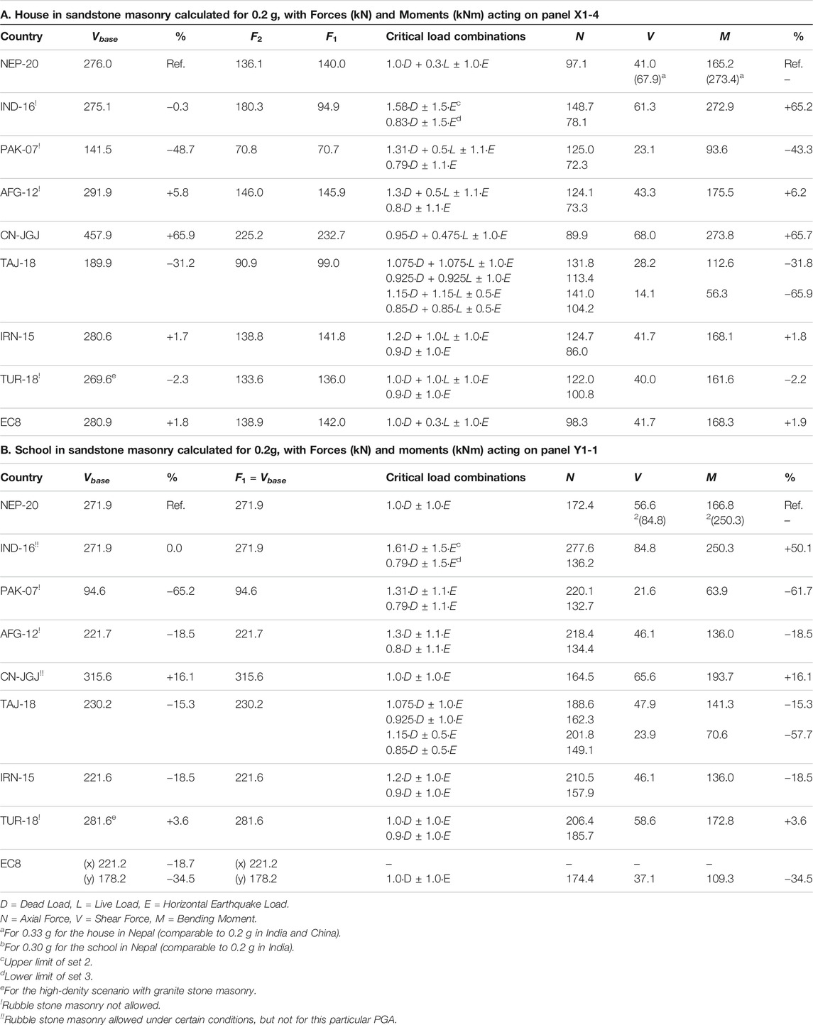
TABLE 9. Final calculations of base shear, story shear, and forces acting on selected masonry panels for the house and the school in random sandstone masonry.
Load Combinations and Vertical Seismic Loads
All codes include sets of load combinations that combine static with earthquake loads, resulting in an upper and lower limit that must be verified for each seismic-load-resisting element of the buildings. NEP-20 and EC8 include just one combination that is the same for both determination of seismic weights and base shear, as well as for verification of the masonry panels, whereas India introduces three different sets. All starting combinations are shown in Table 8B. Then the vertical seismic loads are determined, which is not deemed necessary for low-rise or “simple” buildings in Nepal, China, Iran, Turkey and Eurocode. India introduces a vertical seismic coefficient Av as two-thirds of the horizontal coefficient Ah, of which 30% is added to the load combination, and which affects both DL and LL. Similarly, in Tajikistan 15% (zone 8, simplified approach) of vertical loads is combined with the axial force N, as acting on the walls only. PAK-07 and AFG-12 relate a fraction of the vertical action only to the portion of DL. Since the vertical component acts in both upward and downward directions, and assuming that the effects of the earthquake loads are governing for ULS-verifications, this results in the critical load combinations as shown in Table 9. For ease of comparing, the various symbols for Dead, Live and Earthquake loads are made equal (D, L and E), and only the upper and lower limits are included.
Axial Forces, Shear Forces and Bending Moments
For the house one slender panel (X1–4), and for the school one stocky masonry panel (Y1–1) are selected to analyze the effects of the critical load combinations on the Axial Forces (N), Shear Forces (V) and Bending Moments (M). A worst-case scenario is assumed where spandrels and sills are fully ignored, as well as the beneficial effects of horizontal bands are neglected. It basically results in the analysis of an URM free-standing cantilevered pier (Figure 4), which is not a very realistic scenario, but gives sufficient insight in the seismic demands as dictated by the codes. Since all mass is in the walls, instead of distributing the inertia story forces F1 and F2 by tributary areas (for flexible diaphragms), the forces are redistributed by tributary masses according to the lengths of the main walls in the direction under consideration, plus tributary lengths of the orthogonal walls. Due to the slight asymmetry in the house, this results in a division of 45–55% for the walls in x-direction, and 32–36–32% in y-direction. For the school this is 50–50% and 21–29–29–21% respectively.
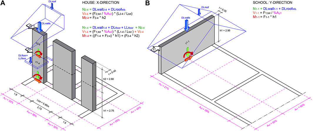
FIGURE 4. Division of mass and internal actions on a cantilevered pier for (A) the house and (B) the school design (all by courtesy of Smart Shelter Foundation).
The calculated values for N, V and M for the critical load combinations are added to Table 9, where for Turkey the highest-density scenario of granite is included. It shows that in almost all cases (except Tajikistan), the load combinations only influence N, where the upper limit checks the capacity of the panels in compression, and the lower limit relates to shear along the horizontal joints of the masonry. It is expected that a higher value of N is beneficial for stocky panels, whereas lower values of N may benefit the bending moment on slender panels. However, identification of the most critical panels can only be determined at a later stage, during a full seismic capacity verification. Overall, Table 9 shows that base shear (second column) is a good indication of which code is most tolerant (Pakistan) and most conservative (China), as the percentages compared to reference country Nepal, after application of the load combinations (last column), remain in the same range. Only India deviates significantly due to the introduction of a seismic load factor 1.5, making the seismic demand similar to China for the house, and highest of all for the school. These highest values match with PGA = 0.33 g for the house and PGA = 0.30 g for the school in Nepal. Since Nepal does allow such higher PGA values for rubble stone (contrary to India and China), these will be taken as the reference and target for the seismic capacity checks in future work. By applying and scaling the percentages in the last column, the seismic demand implications for different seismic hazards can be determined for each country accordingly. Lastly, the weight implications of different types of stones must be considered, which in Nepal and India amounts to 7.1% and in China to 19.2% additional seismic weight for the uppermost limit of granite stone masonry buildings (not added to table).
Conclusion
The total base shear, distribution of forces and load combinations for ULS-verifications (10%PE50y) are analyzed and compared by means of literally applying the seismic codes of selected countries that still (or should) allow the technique of nominally reinforced rubble stone masonry (NRM), for a typical house and school design as built in Nepal. The following is concluded:
- The case study buildings, characterized by heavy stiff walls and light flexible diaphragms, behave differently from most common structures. Main difference is that all lateral-force-generating mass is located in the heavy walls with a ratio of nearly 97.5 vs. 2.5% for the diaphragms including LL (Tables 1 and 2). As a result, the floor inertia forces are distributed to the lateral-resisting elements by tributary wall masses.
- Since generation of inertia forces is proportional to mass, it is important to determine the correct stone typology, as large differences exist between densities for sandstone and granite.
- The codes define conventional ways of lumping the seismic weights at floor levels and leave out the lower half portion at ground level, meaning that over 25% of total weight of the house and nearly 50% of the school is not considered for determination of the seismic effects. This may possibly lead to underestimation of base shear.
- On the other hand, ELF may overestimate the maximum base shear by including the full seismic weight, as opposed to modal methods which combine 85–90% of the effective masses.
- Overestimation may be further caused by the empirical formulas for the fundamental period T1 that are related to the building height H (Table 6), which for short-period buildings leads to the maximum amplification in the response spectrum (Figure 3).
- Another important parameter with high influence on the spectral acceleration is the structural behavior factor, generally taken as 2.0, which seems reasonable for nominally reinforced stone masonry with cement mortar. Too high values may lead to underestimation of the total base shear, especially Pakistan applies a very high behavior factor R = 4.5.
- Most countries (could) accept ELF, S-ELF or S-Modal for the first mode of vibration (TAJ-18), or do not require verification at all (IRN-15, CRO-11 for ag,urm<0.30 g) for “simple regular” structures. India however requires a dynamic approach for all buildings ≥0.05g, which seems not in line with the concept of “non-engineered seismic design”.
- Large variations are seen between the seismic hazard levels and design PGA values of the selected countries, especially at bordering areas (Figure 2). Overall, India and Tajikistan calculate with relatively low design accelerations, which are not based on a probabilistic approach (Table 5). For the calculations 0.2 g was chosen as the reference PGA, which is slightly higher than the highest seismic zone value in India (0.18 g), although still lower than the lowest design value in Nepal (0.25 g).
- For calculation of base shear, many different values for the various applied coefficients are observed (Table 7). However, the resulting base shear for the house (Table 9) is nearly identical in Nepal, India, Afghanistan (ELF), Iran, Turkey, Croatia, and is comparable for Afghanistan (S-ELF). For the school, the differences are higher due to the high variation of importance factors.
- All base shears are calculated on rock soil. For medium and softer soil profiles, the base shear must be multiplied by a soil factor with amplifications ranging from S = 1.15 in EC8 to Fa = 1.6 in AFG-12.
- Base shear in Nepal closely represents the average value of all countries, whereas Pakistan is most tolerant (due to high behavior factor) and China is most conservative (due to high seismic coefficient). The high value of R = 4.5 in Pakistan is questionable and may be revised in the future, which will then result in Tajikistan being most tolerant.
- When analyzing the internal forces at the base of the masonry piers after application of the load combinations, the conclusion above does not change with just one exception; the earthquake loads in India are among the highest and match the Chinese values, due to load combination factor 1.5. Although this analysis is performed on a worst-case (less realistic) scenario for URM free-standing cantilevered piers, it is assumed that for different methods of assessing the base shear seismic demand, the upper and lower limits will always range between the codes of Pakistan (or Tajikistan) and China (and/or India).
- The calculated seismic loads for 0.20 g in China and India, match with the Nepalese design values of 0.33 g for the house and 0.30 g for the school. Since Nepal allows stone masonry in areas with higher seismic hazard levels (opposed to China and India), this code is taken as the reference and starting point for further research. The Nepalese PGA values are set as targets for validation of the masonry panels, whereas other codes can be scaled accordingly by applying the percentages in Table 9.
To summarize, heavy-masonry-light-floor systems with negligible diaphragm action behave different under seismic excitation than most other typologies, such as frame buildings with heavy slabs. Given the observations in this paper, the applicability of the conventional ELF, S-ELF and S-Modal methods for heavy masonry buildings is questionable. The codes however do not introduce different or modified approaches to address these differences. The implications of the above-mentioned observations, such as exclusion of large portions of seismic weight and ignoring the plinth masonry must be carefully assessed, while specific parameters for nominally reinforced stone masonry with cement mortar, such as the behavior factor, damping ratio and natural period of vibration need to be validated. Therefore, the suitability of different (possibly more sophisticated computer-aided) concepts must be analyzed, such as the equivalent frame method and distributed mass system, including an in-depth understanding of the effects of horizontal (and vertical) reinforcements. The seismic demand then needs to be checked against the ultimate capacity of the structures, for which the key lies in the determination of reliable material properties, with focus on the compression, tensile and shear strengths of the masonry, but in such way that these reflect the quality of local materials and workmanship.
To achieve all this, a research initiative is started by the name of SMARTnet, which stands for Seismic Methodologies for Applied Research and Testing of non-engineered Techniques. The philosophy includes a structured research approach that specifically addresses vernacular and traditional construction techniques: “Non-Engineered 2.0.” It is realized that the challenge is huge and the scope of work enormous, for which help is needed. The strategy of SMARTnet envisions a joint approach of global collaboration, to cope with the massive number of material variables, as well as to generate cross-checked data that can be used for calculations and calibration of computer models for non-engineered techniques. SMARTnet invites experts, professionals, academics and final-year students to exchange their knowledge and to support the project with their time and expertise. Fact is that millions of people continue to live in stone houses in South and Central Asia, the Middle East, Northern Africa and Europe as well. They need clear and reliable information that is up-to-date and complete. It is expected that a full validation and justification of the seismic behavior of rubble stone masonry buildings will strengthen the confidence in those countries that still use this technique, as well as creates renewed interest in countries that currently prohibit it.
Data Availability Statement
The original contributions presented in the study are included in the article/Supplementary Material, further inquiries can be directed to the corresponding author.
Author Contributions
MS collected all data, performed all calculations, coordinated all fact-checking through interaction with the experts worldwide and wrote the paper. YA and SS assisted in collection of data, performing of calculations and reviewed, revised and restructured the manuscript.
Funding
This work is supported by the Grant-in-Aid for Scientific Research (KAKENHI) of Japan Society for the Promotion of Science (JSPS) under Grant Number (B) 17H04592, as well as by the Dutch organization Prins Bernhard Cultuurfonds. Their support is greatly appreciated.
Conflict of Interest
The authors declare that the research was conducted in the absence of any commercial or financial relationships that could be construed as a potential conflict of interest.
Acknowledgments
The authors wish to acknowledge everyone that assisted with our search for the national seismic, masonry and building codes, and in particular the following persons for reviewing the drafts, checking of facts and calculations, as well as their invaluable feedback on translations and interpretations of their respective countries’ codes: Assist. Prof. K. Shrestha and J. Bothara (Nepal), Prof. Y. Singh (India), Prof. M. Rafi and S. Qazi (Pakistan), M.Eng. N. Aloko (Afghanistan), Assoc. Prof. T. Miller (ASC, UBC-97), Dr T. Wang, Dr Y. Zhang, MEng. C. Zhong and Assist. Prof. J. Guo (China), Y. Vorfolomeyeva (all Russian-based codes), Prof. T. Negmatov and Dr J. Niyazov (Tajikistan), Prof. U. Begaliev and MEng. A. Stamov (Kyrgyzstan), Dr I. Timchenko and Assist. Prof. I. Salukvadze (Georgia), Dr A. Naderzadeh (Iran), Prof. P. Gülkan and MEng. O. Türkcan (Turkey), Dr E. Mustafaraj and Prof. H. Bilgin (Albania), Dr R. Marques (Portugal), Assoc. Prof. J. Takagi (Japan).
References
ABC-2012. (2012). Afghanistan building code 2012, Afghan structural code (ASC). Kabul: government of Islamic Republic of Afghanistan, Afghanistan National Standard Authority.
Ali, M., Khan, S., and Anwar, M. (2017). Application of BCP-2007 and UBC-97 in seismic vulnerability assessment of gravity designed RC buildings in Pakistan. Front. Struct. Civ. Eng. 11, 396. doi:10.1007/s11709-017-0436-4
Ali, Q., Khan, A., Ashraf, M., Ahmed, A., Alam, B., and Ahmad, N. (2013). Seismic performance of stone masonry buildings used in the Himalayan Belt. Earthquake spectra, J. Earthq. Eng. Res. Inst. 29 (4), 145–162. doi:10.1193/091711EQS228M
Arian, A., Vlosky, R., and Zamani, K. (2007). The wood products Industry in Iran. For. Prod. J. 57 (3), 6–13. doi:10.1007/978-90-481-9550-3_11
Arya, A. S. (1977). “Codes,” in Proceedings of the 6th World conference on earthquake engineering, New Delhi.
Arya, A. S. (2000). “Non-engineering construction in developing countries–An approach toward earthquake risk reduction,” in Proceedings of the 12th World Conference on Earthquake Engineering, Auckland.
ASCE 7-93. (1994). Minimum design loads for buildings and other Structures. New York, NY: American Society of Civil Engineers.
ASCE/SEI 7-10. (2010). Minimum design loads for buildings and other Structures. Reston, VA: American Society of Civil Engineers.
ASCE/SEI 7-16. (2017). Minimum design loads for buildings and other Structures. Reston, VA: American Society of Civil Engineers.
AzDTN 2.3-1. (2014). Construction in Seismic areas (in Azerbaijani). With amendments D1 (2011) and D2. Baku: Committee for Architecture and Urban Planning of the Republic of Azerbaijan.
Bahuguna, A., and Sil, A. (2018). Comprehensive Seismicity, seismic sources and seismic hazard assessment of Assam, North East India. J. Earthquake Eng. 24 (2), 254–297. doi:10.1080/13632469.2018.1453405
BCP-SP-07. (2007). Building code of Pakistan (Seismic provisions—2007). Islamabad: Government of Islamic Republic of Pakistan, Ministry of Housing and Works.
Benedetti, D., Carydis, P., and Pezzoli, P. (1998). Shaking table tests on 24 simple masonry buildings. Earthq. Eng. Struct. Dyn. 27, 67–90.
Bertero, R., and Bertero, V. (2002). Performance-based seismic engineering: the need for a reliable conceptual comprehensive approach. Earthq. Eng. Struct. Dyn. 31, 627–652. doi:10.1002/eqe.146
Bhatia, S., Kumar, M., and Gupta, H. (1999). A probabilistic seismic hazard map of India and adjoining regions. Ann. Geophys., 42 (6), 112. doi:10.4401/ag-3777
Bhatt, D., Chandra, K., Rawal, R., Nandi, S., and Dhyani, P. (2016). Tree diversity of Western Himalaya. Almora: G.B. Pant Institute of Himalayan Environment & Development.
Boyd, O., Mueller, C., and Rukstales, K. (2007). Earthquake hazard maps for Afghanistan, open-file report 2007-1137, Plate 2 of 2. Reston: U.S. Geological Survey.
Charleson, A. (2008). Seismic design for architects - outwitting the Quake. Oxford: Architectural Press.
Das, R., Sharma, M., and Wason, H. (2016). Probabilistic seismic hazard assessment for Northeast India region. Pure Appl. Geophys. 173, 2653–2670. doi:10.1007/s00024-016-1333-9
Decree BKK-2018/11275. (2018). Turkish earthquake hazard map and parameter values. Resmî Gazete n.30364 of 18/03/2018 (in Turkish). Ankara: Disaster and Emergency Management Presidency.
Department of Urban Development and Building Construction. (2015). Design catalogue for reconstruction of earthquake resistant houses, vol. I. Kathmandu: Department of Urban Development and Building Construction (DUDBC).
Dhanvijay, V., Telang, D., and Nair, V. (2015). Comparative study of different codes in seismic assessment. IRJET 2, 4, 1371–1381. doi:10.4324/9780203018866-10
Elmenshawi, A., Sorour, M., Mufti, A., Jaeger, L., and Shrive, N. (2010). Damping mechanisms and damping ratios in vibrating unreinforced stone masonry. Eng. Structures 32, 3269–3278. doi:10.1016/j.engstruct.2010.06.016
EN 1912:2012. (2012). Structural timber—Strength classes—Assignment of visual Grades and species, incorporating corrigendum August 2013. Brussels: European Committee for Standardization.
EN 1990:2002+A1. (2010). Eurocode—basis of Structural design, incorporating corrigenda december 2008 and April 2010. Brussels: European Committee for StaSndardization.
EN 1991-1-1:2002/AC:2009. (2009). Eurocode 1: actions on Structures—Part 1-1: general actions—densities, Self-weight, imposed loads for buildings, incorporating corrigendum March 2009. Brussels: European Committee for Standardization.
EN 1991-1-3:2003. (2009). Eurocode 1: actions on Structures—Part 1-3: general actions—Snow loads, incorporating corrigendum July 2009. Brussels: European Committee for Standardization.
EN 1998-1:2004+A1. (2013). Eurocode 8: design of Structures for earthquake resistance—Part 1: general rules, Seismic actions and rules for buildings, incorporating corrigendum July 2009. Brussels: European Committee for Standardization.
GB 18306-2015. (2016). Seismic ground motion parameters zonation map of China. General Administration of Quality Supervision, Inspection and Quarantine of the People’s Republic of China (in Chinese). Beijing: Springer.
GB 50009-2012. (2012). Load code for the design of building buildings. Ministry of Housing and Urban–Rural Development of the People’s Republic of China, Jointly with General administration of quality Supervision, Inspection and Quarantine of the People's Republic of China (in Chinese). Beijing: Springer.
GB 50011-2010. (2016). Code for Seismic design of buildings, 2016 Edition (in Chinese). Beijing: Ministry of housing and Urban-rural development of the People's Republic of China, jointly with General administration of quality Supervision, Inspection and Quarantine of the People's Republic of China. Beijing: Springer.
GB 50223-2008. (2008). Standard for classification of Seismic protection of buildings constructions. Ministry of Housing and Urban-Rural Development of the People’s Republic of China. Beijing: Springer.
Ghosh, B., Pappin, J., So, M., and Hicyilmaz, K. (2012). “Seismic hazard assessment in India,” in Proceedings of the 15th world Conference on earthquake engineering, Lisbon.
Goda, K., Drukpa, D., Werner, M., Adams, B., Cooper, F., and Haines, D. (2019). Building resilience to earthquakes in Bhutan: a probabilistic Seismic hazard assessment to inform the National building code. Berlin: Springer.
Goel, R., and Chopra, A. (1998). Period formulas for concrete shear wall buildings. J. Struct. Eng. 124 (4), 426. doi:10.1061/(ASCE)0733-9445
GOST 4001-13 (2019). Wall Stones from rocks. Specifications (reprinted in 2019, in Russian). Minsk: Euro-Asian Council for Standardization, Metrology and Certification.
Haziq, D., and Morisako, K. (2017). “Afghanistan building code (ABC): focused on comparative analysis and the viability of Enforcement,” in AEI 2017: resilience of the Integrated building. Editor S. Volz (Oklahoma: The Hague), 138–149.
Imashi, N., and Massumi, A. (2011). A comparative study of the seismic provisions of Iranian seismic code (Standard No. 2800) and International Building Code 2003. Asian J. Civil Eng. Build. Housing 12 (5), 579–596. doi:10.22215/etd/2005-06219
IS 13828:1993. (2018). Improving earthquake resistance of low Strength masonry buildings. Guidelines, 3rd reprint 2008 incl. Amendments nos 1. 2 & 3, reaffirmed 2018. New Delhi: Bureau of Indian Standards.
IS 875 (Part 1):1987. (2018). Code of practice for design loads (other than earthquake) for buildings and Structures, Part 1 Dead loads – unit weights of building materials and Stored materials (Second revision), 9th reprint 2010 (including Amendment No.1), reaffirmed 2018. New Delhi: Bureau of Indian Standards.
IS 875 (Part 2):1987. (2018). Code of practice for design loads (other than earthquake) for buildings and Structures, Part 2 imposed loads (Second revision), 10th reprint 2010 (including Amendment No.1), reaffirmed 2018. New Delhi: Bureau of Indian Standards.
IS 875 (Part 5):1987. (2018). Code of practice for design loads (other than earthquake) for buildings and Structures, Part 5 Special loads and load combinations (Second revision), 7th reprint 2011 (including Amendment No. 1), reaffirmed 2018. New Delhi: Bureau of Indian Standards.
IS-1893(pt.1):2016 (2016). Criteria for earthquake resistant design of Structures. Part 1 general provisions and buildings (sixth revision). New Delhi: Bureau of Indian Standards.
Jain, S., and Rai, D. (2019). Proposed modifications and commentary for code on criteria for earthquake resistant design of Structures IS 1893:2016 (Part 1—general provisions and buildings). Document No.: IITGN-WB-EQ2-V1.0, IITGN-WB-EQ3-V1.0, draft report: IS 1893. Gandhinagar: IITGN – World Bank Project on Seismic Codes.
Jain, S. (2003). Review of Indian seismic code, IS1893 (Part 1): 2002. Indian Concr. J. 77 (11), 1414–1422. doi:10.1115/pvp2002-1449
JGJ 161-2008 (2008). Seismic technical Specification for building construction in town and village (in Chinese). Beijing: Ministry of Housing and Urban-Rural Development of the People's Republic of China.
Khose, V., Singh, Y., and Lang, D. (2012). A comparative study of design base shear for RC buildings in selected seismic design codes. Earthq. Spectra 28 (3), 1047–1070. doi:10.1193/1.4000057
Kirchhoff, J., and Fabian, A. (2010). Forestry sector analysis of the Republic of Tajikistan. Dushanbe: Deutsche Gesellschaft für Technische Zusammenarbeit.
Kwon, O., and Kim, E. (2010). Evaluation of building period formulas for seismic design. Earthquake Eng. Struct. Dyn. 39, 1569–1583. doi:10.1002/eqe.998
Leyendecker, E., Hunt, R., Frankel, A., and Rukstales, K. (2000). Development of maximum considered earthquake ground motion maps. Earthq. Spectra 16: 21–40.
Mahajan, A., Thakur, V., Sharma, M., and Chauhan, M. (2010). Probabilistic seismic hazard map of NW Himalaya and its adjoining area, India. Nat. Hazards 53, 443–457. doi:10.1007/s11069-009-9439-3
Maiti, S., Nath, S., Adhikari, M., Srivastava, N., Sengupta, P., and Gupta, A. (2016). Probabilistic seismic hazard model of West Bengal, India. J. Earthq. Eng. 14, 1–45. doi:10.1080/13632469.2016.1210054
Mazzon, N., Valluzzi, M., Aoki, T., Garbin, E., De Canio, G., and Ranieri, N. (2009). “Shaking table tests on two multi-leaf stone masonry buildings,” in Proceeding of 11th Canadian masonry symposium, Toronto.
Medvedev, S., and Sponheuer, W. (1969). “Scale of seismic intensity,” in Proceedings of the 4th world conference on earthquake engineering, Santiago de Chile.
Mukhadze, T., and Timchenko, I. (2000). “Analysis of New seismic building codes of CIS countries,” in Earthquake hazard and seismic risk reduction. Advances in natural and Technological hazards research Editors S. Balassanian, A. Cisternas, and M. Melkumyan (Dordrecht: Springer).
Nakamura, Y., Derakhshan, H., Magenes, G., and Griffith, M. (2017). Influence of diaphragm flexibility on seismic response of unreinforced masonry buildings, J. Earthq. Eng. 21 (6), 935–960. doi:10.1080/13632469.2016.1190799
NBC-105. (2020). Seismic design of buildings in Nepal. Kathmandu: Department of Urban Development and Building Construction.
NBC 102:1994. (2007). Unit weight of materials, V1.RV4, reprint. Kathmandu: Department of Urban Development and Building Construction.
NBC 103:1994. (2007). Occupancy load (imposed load), V1.RV4, reprint. Kathmandu: Department of Urban Development and Building Construction.
NBC 202:2015. (2015). Guidelines on: load bearing masonry. Kathmandu: Department of Urban Development and Building Construction.
NBRI-6. (2013). National building regulations of Iran, Part 6: loads on buildings, Third Edition (in Farsi). Tehran: Ministry of Road and Urban Development.
Neupane, P., and Shrestha, S. (2015). Comparative analysis of seismic codes of Nepal and India for RC buildings. Int. J. Eng. Trends Technol. 28 (2), 102–105. doi:10.14445/22315381/ijett-v28p220
nHRN EN 1998-1:2011/NA. (2011). Eurocode 8—design of Structures for earthquake resistance—Part 1: general rules, Seismic actions and rules for buildings—National Annex (in Croatian). Zagreb: Croatian Standards Institute.
Orwa, C., Mutua, A., Kindt, R., Jamnadass, R., and Simons, A. (2009). Agroforestree database: a tree reference and Selection Guide Version 4.0. World Agroforestry Centre, Kenya. Available online at: http://www.worldagroforestry.org/output/agroforestree-database (Accessed November 16, 2020).
Pallav, P., Raghukanth, S., and Singh, K. (2012). Probabilistic seismic hazard estimation of Manipur, India. J. Geophys. Eng. 9, 516–533. doi:10.1088/1742-2132/9/5/516
PN 01.01-09. (2012). Construction Norms and rules—Seismic construction. With Amendment No.1 (in Georgian). Tbilisi: Minister of Economic Development of Georgia.
Priestley, M., Calvi, G., and Kowalsky, M. (2007). Displacement-based Seismic design of Structures. Pavia: IUSS Press.
RABC 20.04. (2020). Earthquake resistant construction. Design codes (in Armenian). Yerevan: Ministry of Urban Development of the Republic of Armenia.
Rahman, M., Bai, L., Khan, N., and Li, G. (2017). Probabilistic seismic hazard assessment for Himalayan-Tibetan region from historical and Instrumental earthquake catalogs. Pure Appl. Geophys. 12, 33–39. doi:10.1007/s00024-017-1659-y
Rout, M., Das, J., Das, K., and Das, R. (2015). Probabilistic seismic hazard assessment of NW and central Himalayas and the adjoining region. J. Earth Syst. Sci. 124, 577–586. doi:10.1007/s12040-015-0565-x
Schildkamp, M., and Araki, Y. (2019b). Cost analysis of mountain schools in Nepal: comparison of earthquake resistant features in rubble stone masonry vs. Concrete Block masonry. Front. Built Environ. 5, 55. doi:10.3389/fbuil.2019.00055
Schildkamp, M., and Araki, Y. (2019a). School buildings in rubble stone masonry with cement mortar in seismic areas: literature review of seismic codes, technical norms and practical manuals. Front. Built Environ. 5, 13. doi:10.3389/fbuil.2019.00013
Schildkamp, M., Silvestri, S., and Araki, Y. (2020). Rubble stone masonry buildings with cement mortar: design specifications in seismic and masonry codes worldwide. Front. Built Environ. 6, 83. doi:10.3389/fbuil.2020.590520
Shi, G., Hu, F., and Shi, Y. (2016). Comparison of seismic design for steel moment frames in Europe, the United States, Japan and China. J. Construct. Steel Res. 127, 41–53.
SN KR 20-02:2018. (2018). Earthquake engineering. Seismic design codes (in Kyrgyz and Russian). Bishkek: State Agency of Architecture, Construction and Housing and Communal Services under the Government of the Kyrgyz Republic.
SNiP II-25-80. (1989). Wooden Structures, with Amendment 1 (in Russian). Moscow: State Committee of the Council of Ministers of the USSR for Construction.
SNiP RT 20-01-2012. (2016). Loads and effects, with amendments (in Russian). Dushanbe: Agency for Construction and Architecture under the Government of the Republic of Tajikistan.
SNiP RT 22-07-2018. (2019). Earthquake-resistant construction (in Russian). Dushanbe: Agency for Construction and Architecture under the Government of the Republic of Tajikistan.
SNT 2.01.08-99. (2000). Construction in Seismic regions. Section 1: residential, public, industrial buildings and Structures (in turkmen and Russian). Ashgabat:National Committee for Architectural and Construction Control under the Cabinet of Ministers of Turkmenistan.
SP 14.13330.2018. (2018). Construction in Seismic areas. Updated edition of SNiP II-7-81* (in Russian). Moscow: Ministry of Construction Industry, Housing and Utilities Sector of the Russian Federation.
SP 63.13330.2018. (2019). Concrete and reinforced concrete Structures. General Provisions. Updated Edition of SNiP 52-01-2003, with Amendment N1 (in Russian). Moscow: Ministry of Construction Industry, Housing and Utilities Sector of the Russian Federation.
Standard 2800 (2015). Iranian code of practice for seismic resistant design of buildings, 4th Edn. (in Farsi). Tehran: Building and Housing Research Center.
Stein, S., Brooks, E., Spencer, B., and Liu, M. (2018). Should all of Nepal Be treated as having the same earthquake hazard? In: J. Kruhl, R. Adhikari, and U. Dorka (eds). Living under the Threat of earthquakes. Cham: Springer.
Tallett-Williams, S., Gosh, B., Wilkinson, S., Fenton, C., Burton, P., and Whitworth, M. (2016). Site amplification in the Kathmandu Valley during the 2015 M7.6 Gorkha, Nepal earthquake. Bull. Earthq. Eng. 14, 3301–3315. doi:10.1007/s10518-016-0003-8
Tamrakar, A., and Chen, S. (2017). “Comparison of the seismic design code for buildings of Nepal with the Chinese, European and American seismic design codes,” in Proceedings of the 30th KKHTCNN Symposium on Civil Engineering, Taipei.
TBDY. (2018). Turkish seismic building Regulations. Resmî Gazete n.30364 of 18/03/2018 (in Turkish). Ankara: Disaster and Emergency Management Presidency.
Tomazevic, M., and Lutman, M. (2007). Heritage masonry buildings in urban Settlements and the requirements of Eurocodes: Experience of Slovenia. Int. J. Archit. Herit. 1 (1), 108–130. doi:10.1080/15583050601126186
TS-ISO-9194. (1997). Bases for design of Structures; actions due to Self-weight of Structures, Non-Structural elements and Stored materials; density (in Turkish). Ankara: Turkish Standard Institution.
UBC-1997. (1997). Uniform building code, volume 2, structural engineering design provisions. Whittier, CA: International Conference of Building Officials.
Vasconcelos, G., and Lourenço, P. (2009). In-plane Experimental behavior of stone masonry walls under cyclic loading. J. Struct. Eng. 135 (10), 1269–1277. doi:10.1061/(ASCE)ST.1943-541X.0000053
Vision 2000 Committee. (1995). Performance based Seismic engineering of buildings. Sacramento, CA: Structural Engineers Association of California.
Vratsanou, V. (2000). “Earthquake resistant design of unreinforced masonry buildings—a comparative study of the European seismic codes,” in Proceedings of the 12th International Brick/Block Masonry Conference, Madrid.
Xiaoguang, C., Jingshan, B., Youwei, S., Jianyi, Z., and Yudong, Z. (2012). “Comparison of seismic fortification criterion of eight Asian countries,” in Proceedings of the 12th World Conference on Earthquake Engineering, Lisbon.
Keywords: rubble stone masonry, seismic demand parameters, seismic codes, base shear formulas, seismic load combinations, seismic weight, structural behavior factor, peak ground acceleration
Citation: Schildkamp M, Silvestri S and Araki Y (2021) Rubble Stone Masonry Buildings with Cement Mortar: Base Shear Seismic Demand Comparison for Selected Countries Worldwide. Front. Built Environ. 7:647815. doi: 10.3389/fbuil.2021.647815
Received: 30 December 2020; Accepted: 01 February 2021;
Published: 31 March 2021.
Edited by:
Ricardo Monteiro, University School for Advanced Studies, University Institute of Higher Studies in Pavia, ItalyCopyright © 2021 Schildkamp, Silvestri and Araki. This is an open-access article distributed under the terms of the Creative Commons Attribution License (CC BY). The use, distribution or reproduction in other forums is permitted, provided the original author(s) and the copyright owner(s) are credited and that the original publication in this journal is cited, in accordance with accepted academic practice. No use, distribution or reproduction is permitted which does not comply with these terms.
*Correspondence: Martijn Schildkamp, aW5mb0BzbWFydHNoZWx0ZXJyZXNlYXJjaC5jb20=