 Piyush Punetha
 Krijan Maharjan
 Sanjay Nimbalkar
- School of Civil and Environmental Engineering, University of Technology Sydney, Sydney, NSW, Australia
The critical zones are the discontinuities along a railway line that are highly susceptible to differential settlement, due to an abrupt variation in the support conditions over a short span. Consequently, these zones require frequent maintenance to ensure adequate levels of passenger safety and comfort. A proper understanding of the behavior of railway tracks at critical zones is imperative to enhance their performance and reduce the frequency of costly maintenance operations. This paper investigates the dynamic behavior of the critical zone along a bridge-open track transition under moving train loads using two-dimensional finite element approach. The influence of different subgrade types on the track behavior is studied. The effectiveness of using geogrids, wedge-shaped engineered backfill and zone with reduced sleeper spacing in improving the performance of the critical zone is evaluated. The numerical model is successfully validated against the field data reported in the literature. The results indicate that the subgrade soil significantly influences the track response on the softer side of the critical zone. The difference in vertical displacement between the stiffer and the softer side of a track transition decreases significantly with an increase in the strength and stiffness of the subgrade soil. The subgrade layer also influences the contribution of the granular layers (ballast and subballast) to the overall track response. As the subgrade becomes stiffer and stronger, the contribution of the granular layers to the overall track displacement increases. The mitigation techniques that improve the stiffness or strength of granular layers may prove more effective for critical zones with stiff subgrade than critical zones with soft subgrade. Among all the mitigation techniques investigated, the wedge-shaped engineered backfill significantly improved the performance of the critical zone by gradually increasing the track stiffness.
Introduction
The critical zones are the discontinuities along the railway tracks that experience a rapid degradation in track geometry due to an abrupt variation in stiffness, damping characteristics and support conditions. These zones include the transitions between ballasted and slab tracks, open track and stiff structure, such as bridge, culvert, tunnel or underpass, tracks with concrete and wooden sleepers, special track works and road crossings. The inconsistent track response on either side of a critical zone renders it highly susceptible to differential settlement. Consequently, these zones require frequent maintenance, which incurs significant costs to the railroad industry, leads to train delays and reduces the track efficiency (Li and Davis, 2005; Mishra et al., 2017). Figure 1 shows an example of the transition between an open track and stiff structure such as a bridge or an underpass. The track is supported by subgrade soil on one side of the transition, while a concrete slab supports the other side. Thus, two zones are formed on either side of a track transition, one with lower stiffness and the other with a higher track stiffness. During a train passage, the track founded on subgrade soil (i.e., with a lower track stiffness) inevitably deforms more than the track supported by a concrete slab. This uneven deformation accumulates with repeated train passage and leads to the formation of dips or bumps near the bridge/underpass approach, which endangers the safety of the train operations and demands maintenance. The differential deformation also results in the wear and tear of the track, bridge and vehicle components.
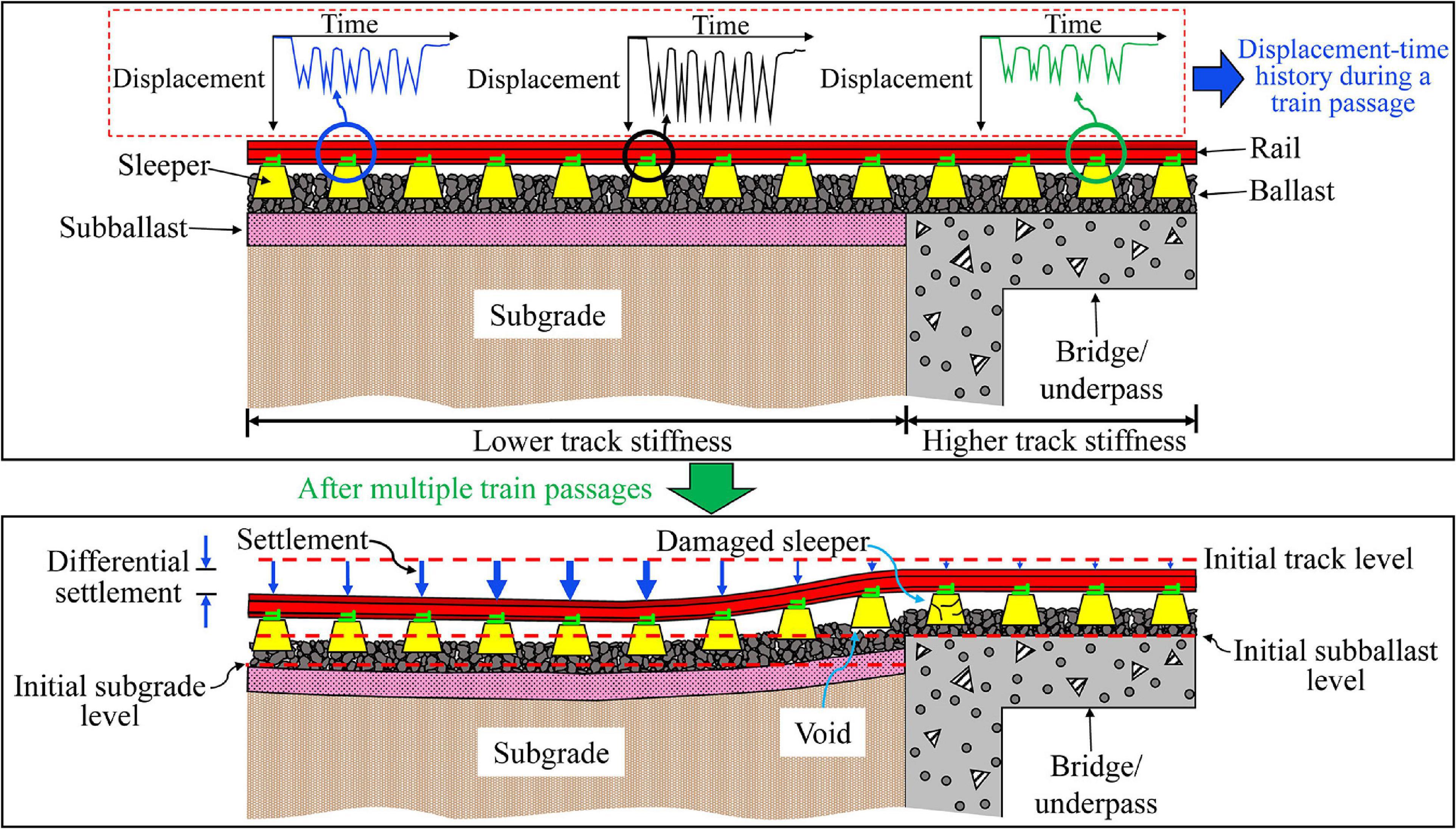
Figure 1. Transition zone between an open track and stiff structure such as a bridge or underpass.
Numerous techniques have been proposed to mitigate the problems associated with the critical zones. Most of the mitigation methods are intended to decrease the stiffness difference in the critical zone by either increasing the stiffness of the softer side, reducing the stiffness of the stiffer side or producing a smooth transition of track stiffness (Kerr and Moroney, 1993; Li and Davis, 2005; Nimbalkar et al., 2020). The stiffness on the softer side can be increased by using geosynthetics such as geocells, hot-mix asphalt layer, cement grouting or other ground improvement techniques. Similarly, the stiffness on the stiffer side can be reduced by employing soft rail pads, under sleeper pads, ballast mats or plastic sleepers (Nimbalkar et al., 2012). The reinforced concrete approach slabs or wedge-shaped engineered fills can also be provided at the critical zones to generate a smooth transition in track stiffness (Asghari et al., 2021). However, the field investigations in the past have revealed that these mitigation measures may not necessarily be effective for each critical zone due to the site-specific nature of the problem (Coelho and Hicks, 2015). Therefore, it is essential to understand the dynamic behavior of the tracks in these critical zones before applying an appropriate mitigation measure.
Several researchers have conducted field investigations in the track transitions to understand their behavior and have identified the probable causes of the associated problems (Li and Davis, 2005; Stark and Wilk, 2015; Coelho et al., 2017; Boler et al., 2018; Wang et al., 2018). These investigations revealed that the root cause of the problem needs to be identified before applying an appropriate mitigation measure. However, the field investigations are time-consuming, expensive and the number of influencing factors are too large for reliable parametric studies. Experimental investigations may help in understanding the behavior of the tracks and to identify the critical parameters that influence their response. However, the size of the physical models in experiments is often limited due to financial issues.
An alternative approach is to predict the response of the track in critical zones using numerical modeling techniques. Several researchers have developed two and three-dimensional finite element models of the railway tracks in critical zones to better understand their behavior and evaluate the performance of various mitigation measures (Gallego and López Pita, 2009; Shahraki et al., 2015; Varandas et al., 2016; Wang and Markine, 2018; Hu et al., 2019; Asghari et al., 2021). However, most of the analyses ignored the elastoplastic nature of the track materials and simulated the behavior of track layers as elastic. The assumption of elastic behavior neglects the irrecoverable deformations of the railway track layers under the repeated traffic loading, which leads to inaccurate prediction of the track response. Therefore, the behavior of the geotechnical layers must be simulated using more appropriate elastoplastic constitutive models to enhance the reliability and accuracy of the predicted results. For instance, Coelho and Hicks (2015) studied the dynamic behavior of an embankment-culvert transition zone, in which approach slabs were provided before and after the culvert, using a three-dimensional (3D) FE model. It was observed that the approach slab failed to satisfactorily fulfill its intended function of gradually increasing the track support stiffness from the softer side to the stiffer side of the transition. Interestingly, the presence of approach slab increased the stress under the free end, which may lead to localized irrecoverable deformations in the soil. However, the plastic deformations were not captured in the analysis since the soil was assumed as an elastic material.
There is a limited understanding regarding the contribution of each substructure layer on the overall track displacement and their mutual interaction. In the field study by Li and Davis (2005), it was observed that the mitigation techniques such as geocells, hot-mix asphalt layer and cement-stabilized backfill were ineffective in alleviating the differential settlement problem at bridge-embankment transition zones. This was due to the fact that the techniques were aimed at strengthening the approach subgrade, which had less contribution toward the track settlement, compared to the ballast layer. Thus, the quantification of the relative contribution of each layer to the overall track response is essential for selecting an appropriate mitigation strategy. The displacements of the granular layers (ballast or subballast) also depend on the underlying subgrade type. Punetha et al. (2020a) observed that the deformations in the ballast and the subballast layers in an open track are much higher when the subgrade soil is stiff compared to the case when the subgrade soil is soft. However, the influence of subgrade soil properties on the performance of the transition zones is not yet fully perceived.
The present study investigates the dynamic response of a bridge-open track transition zone under moving train loads using a two-dimensional finite element model. The moving train load is simulated by applying a vertical point load at different rail nodes, whose magnitude varies with time. The accuracy of the model predictions is investigated by comparing the predicted results with the field investigation data reported in the literature. The behavior of track layers in the numerical model is simulated using the elastoplastic constitutive models. The advantage of employing elastoplastic constitutive models is demonstrated by comparing the track responses using elastic and elastoplastic models for subgrade soil.
The influence of subgrade layer type on the overall track behavior is investigated by considering four different types of subgrade layers, namely, poor (soft clay), fair (medium clay), good (dense sand) and hard rock. For this analysis, the material parameters of the subgrade layer are varied, without changing the geometry of the railway track. The effect of subgrade layer type is assessed by comparing the variation of: (a) vertical rail displacement along the length of the railway track; (b) variation of vertical stress with depth; and (c) variation of vertical displacement with depth; for the four different type of subgrade layers.
Subsequently, the performance of three different mitigation techniques, which are used to minimize the differential displacement along the track transition, is assessed. These techniques include the use of geogrids, wedge-shaped engineered backfill, and zone with reduced sleeper spacing near the bridge approach. The performance of the mitigation techniques is assessed by comparing the response of the track with and without the use of the mitigation measures.
Development of Finite Element Model
The dynamic behavior of the railway track along a bridge-open track transition zone has been analyzed using the finite element program, PLAXIS 2D (PLAXIS BV, 2017). Figure 2A shows the two-dimensional (2D) plane-strain finite element (FE) model of the bridge-open track transition zone. The total length of the model is 80 m, and the span of the bridge is 10 m. The superstructure is identical throughout the length of the track and comprises of rail and sleepers. The substructure of the open track consists of ballast, subballast and subgrade layers, whereas the track on the bridge is supported by ballast and concrete slab (bridge deck). The thickness of ballast, subballast and subgrade layers are considered as 0.3, 0.15, and 5 m, respectively. The nodes at the bottom boundary of the model are considered fixed, i.e., their movement is restricted in horizontal and vertical directions. An absorbent boundary is provided at the sides (left and right boundaries) to prevent spurious reflections of stress waves.
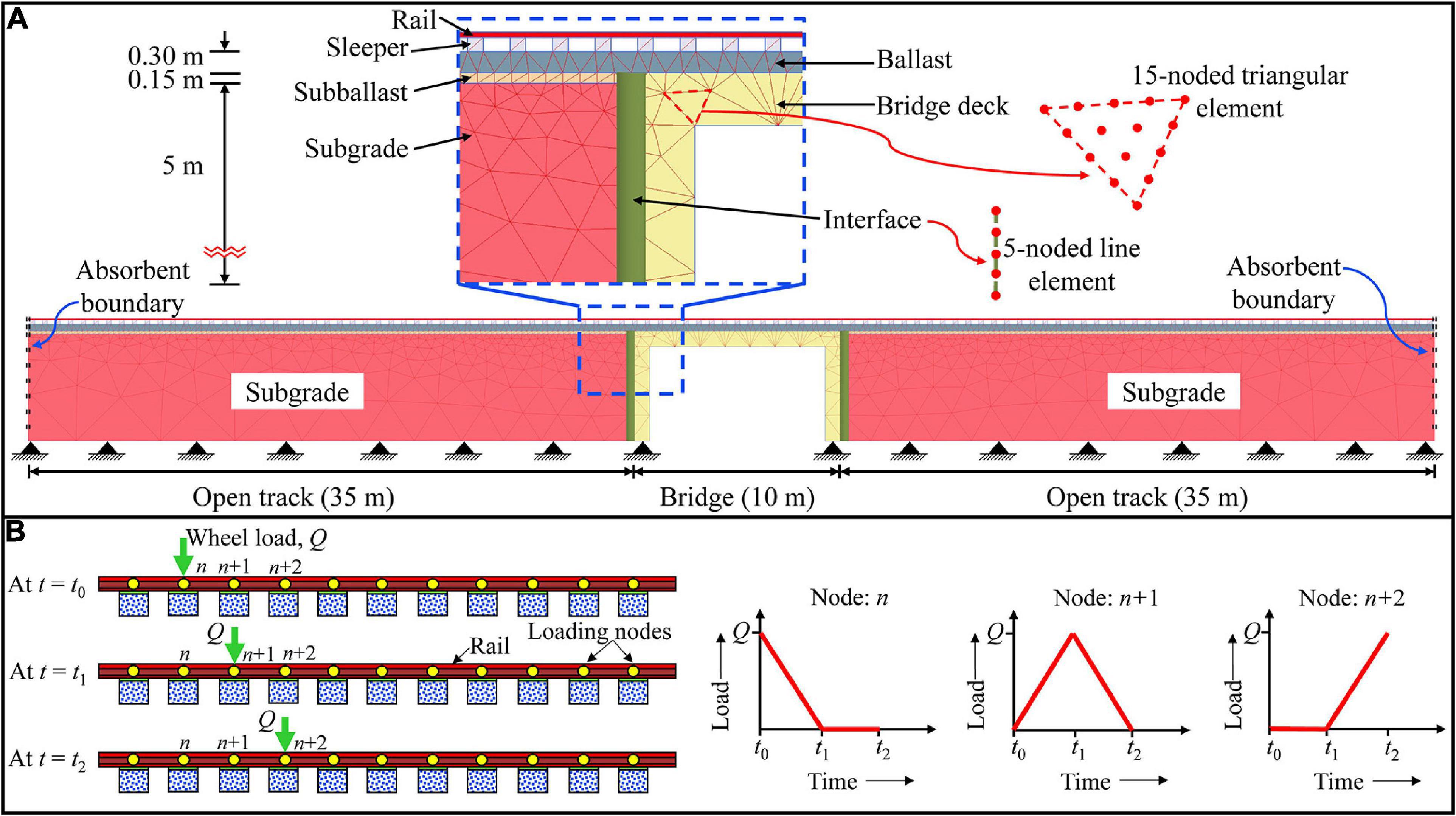
Figure 2. (A) Finite element mesh discretization of the track model; (B) procedure used to calculate the moving train loads.
All the track components are discretized using 15-noded triangular elements, which provide a fourth-order interpolation for displacement and employs twelve Gauss points for numerical integration. The frictional behavior between the bridge abutment and substructure layers has been simulated using 5-noded interface elements available in PLAXIS 2D. The finite element model comprises of 3,330 elements. A medium mesh with enhanced refinements is chosen for the model based on the findings of the mesh sensitivity analysis. To improve the accuracy of the predictions, a local mesh refinement is carried out near the interfaces, corners and the loading zone.
The 2D FE analysis has been employed in the present study because it provides reasonably accurate results despite having limitations such as the inability to realistically simulate three-dimensional loading due to the moving train, lateral spreading of the granular layers along track transverse direction and complex geometries such as ballast profile, rail fasteners and three-dimensional geoinclusions. The main advantages of using a 2D FE model include its simplicity, requirement of low computational effort and less time than the 3D FE model. The 2D model usually involves a few input parameters and can be readily developed by practicing engineers to solve complex problems.
Material Properties
The rail, sleepers, abutment and bridge deck are simulated as linear elastic materials. A hardening soil model has been employed for the ballast layer to realistically capture its strain-hardening behavior under train-induced repeated loads (Indraratna and Nimbalkar, 2013). The response of subballast and subgrade layers is simulated using the classical Mohr-Coulomb elastic-perfectly plastic model with a non-associated flow rule. Table 1 shows the values of the material parameters used for the simulation of the track response. The values of the parameters are selected based on the published literature (Indraratna and Nimbalkar, 2013; Ribeiro et al., 2014; Li et al., 2018; Jiang and Nimbalkar, 2019; Punetha and Nimbalkar, 2021). The dynamic parameters of the railway track components can also be obtained by using the experimental modal analysis (Kaewunruen and Remennikov, 2007).
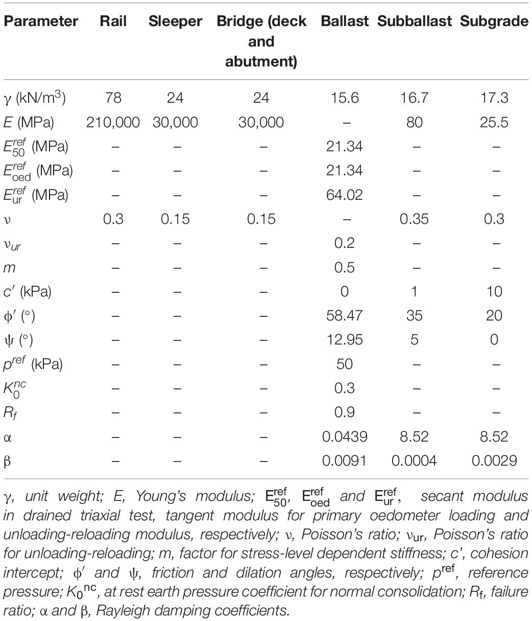
Table 1. Material parameters used in the analysis.
The material damping in the present study is incorporated by means of Rayleigh damping coefficients α and β. These parameters depend on two controlling frequencies and the damping ratio associated with each frequency. The controlling frequencies generally correspond to the first mode of vibration of the material layer and the predominant frequency of input loading (Nimbalkar et al., 2012). The damping ratio for the soils can be obtained by conducting laboratory cyclic triaxial tests as per ASTM D3999 (2011).
Moving Load Simulation
The moving train load in this study is simulated by applying a time-varying vertical load at different rail nodes (also known as loading nodes) (Hall, 2003). Figure 2B shows the procedure used to calculate the moving wheel loads. In this method, the wheel load is assumed as a triangular pulse distributed among three loading nodes. With reference to Figure 2B, consider that the wheel is located at the loading node, “n” at time instant “t0.” The magnitude of load at nodes n, n+1 and n+2 are Q, 0 and 0, respectively. As the wheel moves toward the node n+1, the magnitude of the load at node n decreases, while, it increases for node n+1 and reaches a maximum value of Q when the wheel is directly above node n+1 (i.e., at time instant t1). Similarly, as the wheel approaches node n+2, the load at n+1 decreases and becomes equal to zero as soon as the wheel reaches the node n+2 (at time instant t2). The resulting load-time history at the three nodes is also shown in Figure 2B. Using a similar procedure, the load-time history during a train passage is calculated at each loading node along the entire track length. In this study, the loading nodes are spaced at equal intervals of 0.6 m, which is identical to the sleeper spacing.
Numerical Analyses
The 2D plane-strain dynamic finite element simulations have been used to predict the response of the bridge-open track transition zone under moving train loads. The results are discussed for one complete passage of the Acela express passenger train, consisting of 32 axles, at a speed of 100 km/h. The axle load in this study is considered as 20 t with a dynamic amplification factor of 1.35 (Nimbalkar and Indraratna, 2016). Initially, the dynamic response of the track with nominal values of the parameters is simulated. Subsequently, the influence of subgrade type on the dynamic track response is evaluated. Four different types of subgrade are considered, namely, poor (soft clay), fair (medium clay), good (dense sand) and hard rock. Table 2 lists the properties of the four types of subgrade soils considered in this study. The stiffness and strength of the hard rock is maximum, followed by good, fair and poor subgrades. Finally, three different mitigation measures are provided in the vicinity of the bridge and their influence on the dynamic track response is evaluated. These measures include the addition of geogrid layer at the ballast-subballast interface (GR), use of wedge-shaped engineered fill (EW), and the reduction of sleeper spacing (RS) near the bridge approach.
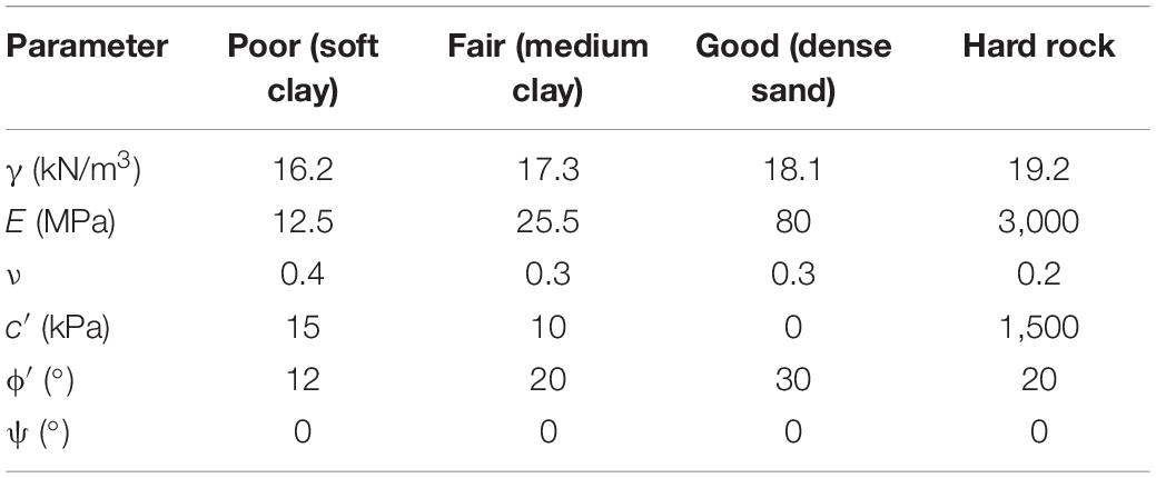
Table 2. Material parameters for different subgrade types.
The length of geogrid layer is taken as 10 m and it is modeled as a linear elastic tension member. To realistically simulate the geogrid-soil interface behavior, five-noded interface elements are provided along both sides of the geogrid. The wedge shaped engineered fill is provided near both sides of the bridge approach. The top width, thickness and side slope of the engineered fill are considered as 3 m, 5.15 m, 1V:1H, respectively (Ribeiro et al., 2014). The behavior of the engineered fill has been simulated using elastic-perfectly plastic Mohr-Coulomb constitutive model with a non-associated flow rule. The Young’s modulus (E), Poisson’s ratio (ν), cohesion (c′), friction angle (ϕ′) and dilation angle (ψ) for the engineered fill layer are considered as 10,000 MPa, 0.3, 300 kPa, 30° and 1°, respectively (Ribeiro et al., 2014). In the third countermeasure, a zone of length 10 m, with a sleeper spacing of 0.4 m, is provided on both sides of the bridge approach. The sleeper spacing is 0.6 m elsewhere. It must be noted that all the three techniques have been analyzed independently.
Model Validation
The accuracy of the 2D plane-strain finite element model in predicting the response of railway tracks in the critical zone has been investigated by comparing the model predictions with the field measurements reported by Paixão et al. (2014). Paixão et al. (2014) recorded the dynamic response of the railway tracks along an underpass-embankment transition zone, during the passage of Portuguese Alfa pendular passenger train. The transition zone comprised of two wedge-shaped backfills between the open track and the underpass, on both sides. The two wedge-shaped backfills were constructed using cement bound mixture (CBM) and unbound granular materials (UGM). In the present study, both the backfills are modeled using the classical Mohr-Coulomb elastic-perfectly plastic model. The UGM with the properties, E = 1,030 MPa, ν = 0.3, c′ = 1 kPa, ϕ′ = 35° and ψ = 5° is simulated. The CBM with the properties, E = 10,000 MPa, ν = 0.3, c′ = 300 kPa, ϕ′ = 30° and ψ = 1° is considered. Figure 3 shows a comparison of the rail vertical displacement-time history recorded in the field, with the results predicted using the 2D finite element model developed in PLAXIS. It can be observed that the predicted results are in an acceptable agreement with the field data at both 1.8 and 8.4 m away from the underpass. The rail vertical displacement is lower at 1.8 m from the underpass as compared to 8.4 m. This difference in displacement is due to much stiffer CBM fill below the track at 1.8 m as compared to the UGM fill at 8.4 m from the underpass.
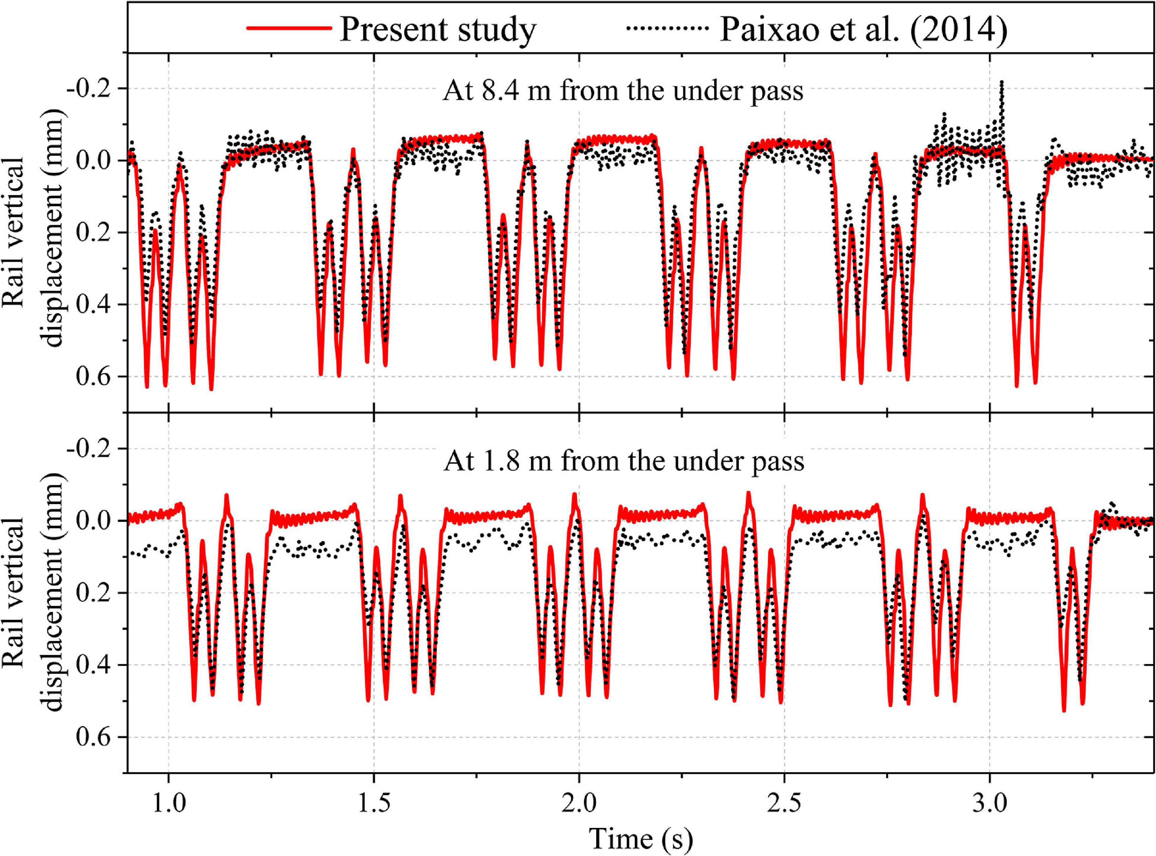
Figure 3. Comparison of model predictions with the data reported by Paixão et al. (2014).
The present model slightly overestimates the vertical displacement at both 1.8 and 8.4 m from the underpass. The overestimation in vertical displacement may be attributed to the inability of the selected constitutive models to accurately predict the response of the geomaterials. The accuracy of the model predictions may be increased further by using more advanced constitutive models, implemented via appropriate user subroutines. Nevertheless, the predicted displacement time-history record is in good agreement with the field investigation data reported by Paixão et al. (2014). Thus, the present 2D plane-strain finite element model can predict the response of the railway track in the critical zones with reasonable accuracy.
Results and Discussion
Influence of Subgrade Type
Figure 4 shows the variation of vertical rail displacement along the length of the railway track in the critical zone. It can be observed that the displacement is maximum for poor subgrade, followed by fair subgrade, good subgrade and hard rock. The difference in vertical displacement between the bridge section and the open track is 12, 8.1, and 2.5 mm for the poor, fair and good subgrade types, respectively. However, the vertical rail displacement is identical at both the bridge and open track location for the hard rock. Thus, the displacement of open track decreases with an increase in the stiffness and strength of subgrade soil. Therefore, the performance of the critical zones with poor subgrade soil can be significantly improved by employing ground improvement techniques that increase the strength and stiffness of the soil.
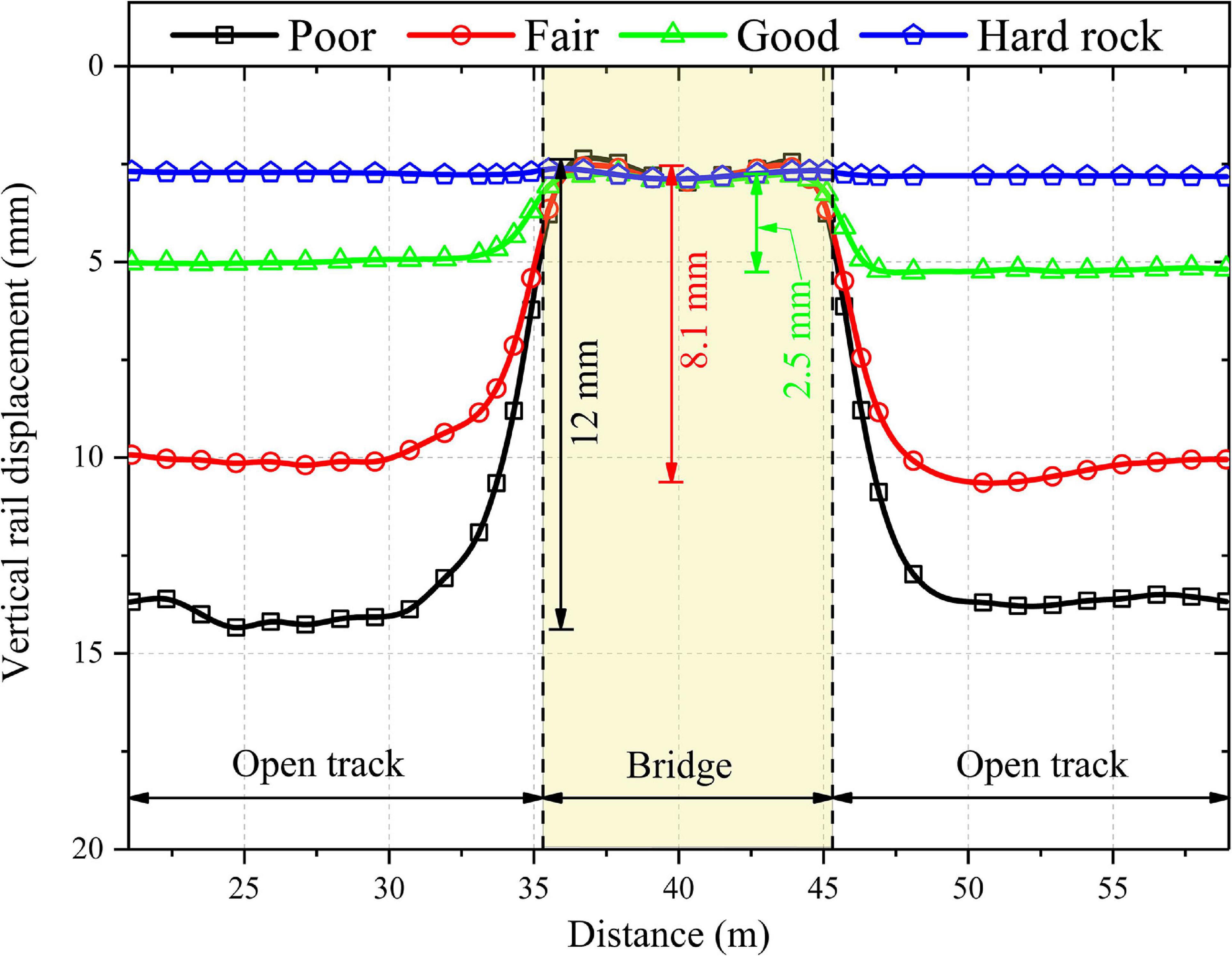
Figure 4. Variation of vertical rail displacement along the length of the track for four different subgrade types.
Figure 5 shows the variation of vertical displacement with depth at two different locations along the track (3.5 and 9.5 m away from the bridge) for four different subgrades. It can be observed that the displacement decreases with an increase in depth. Moreover, the contribution of the granular layers (ballast and subballast) to the overall track displacement increases as the subgrade becomes stiffer and stronger. The contribution of ballast layer to the overall displacement of the track substructure at 3.5 m from the bridge is 16, 24, 47, and 91% for poor subgrade, fair subgrade, good subgrade and hard rock, respectively. Similarly, the contribution of ballast layer to the overall displacement of track substructure, at 9.5 m from the bridge, is 16, 22, 45, and 91% for poor subgrade, fair subgrade, good subgrade and hard rock, respectively. Thus, the response of the granular layers (e.g., ballast) is significantly affected by the subgrade layer type. The mitigation techniques that improve the stiffness or strength of granular layers may prove more effective for critical zones with stiff subgrade than critical zones with soft subgrade. For instance, 3D geoinclusions such as geocells, which improve the properties of granular layers through confinement (Punetha et al., 2020b), are more beneficial for critical zones with a stiff subgrade.
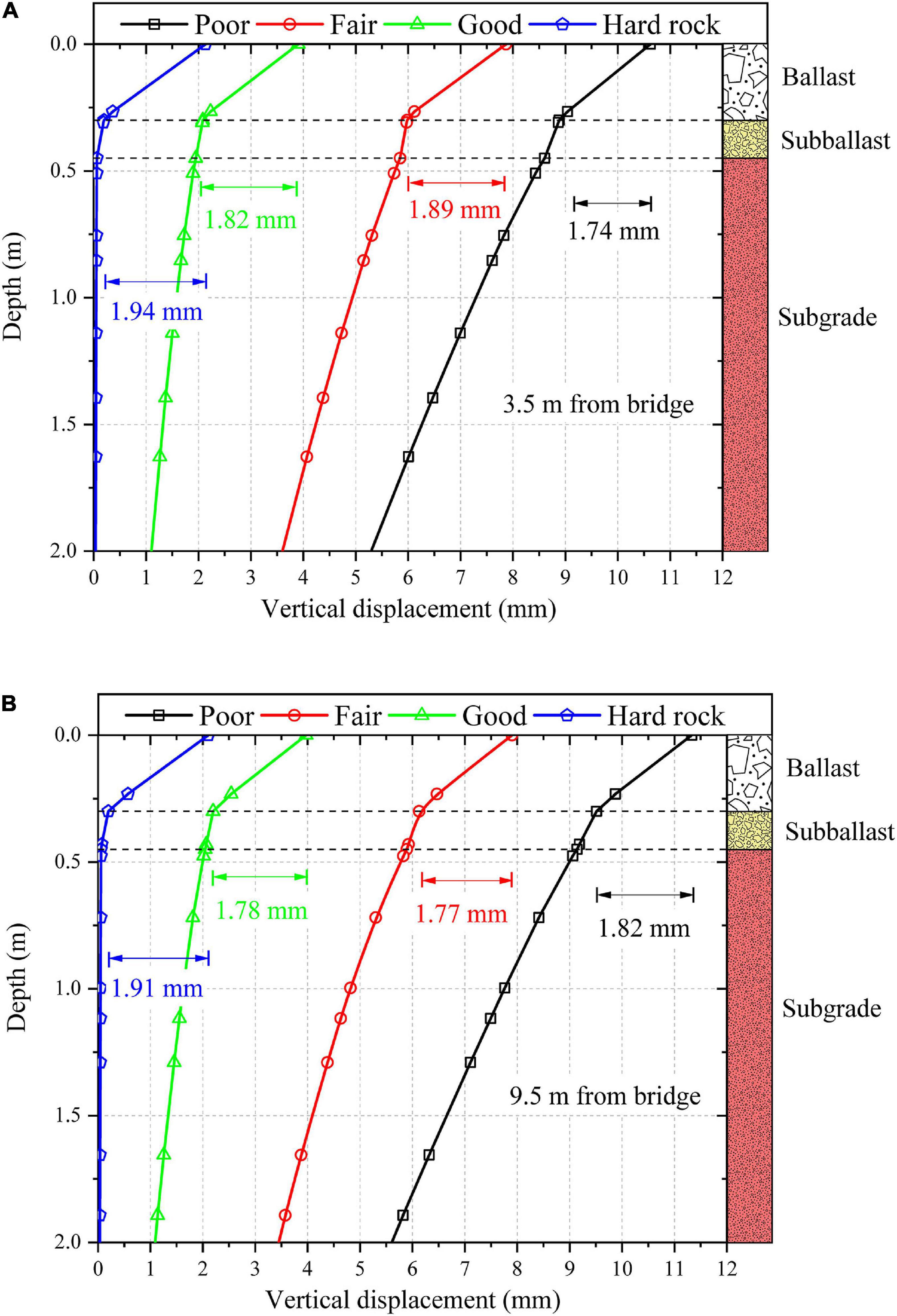
Figure 5. Variation of vertical displacement with depth for four different subgrade types at (A): 3.5 m from the bridge; (B) 9.5 m from the bridge.
Figure 6 shows the increase in vertical stress with depth at two different locations along the track (3.5 and 9.5 m away from the bridge) for four different subgrades. It can be observed that the vertical stress increment decreases with an increase in depth for all the subgrades. The vertical stress increases with an increase in the strength and stiffness of the subgrade, at both 3.5 and 9.5 m from the bridge. This effect is more pronounced in the subballast layer and the top of the subgrade layer. The vertical stress increment at the subgrade top is 49.9, 64.9, and 79.5 kPa for poor subgrade, fair subgrade and hard rock, respectively, at 3.5 m from the bridge. It can be noted that the influence of subgrade type on the vertical stress increment becomes negligible at depths greater than 2 m.
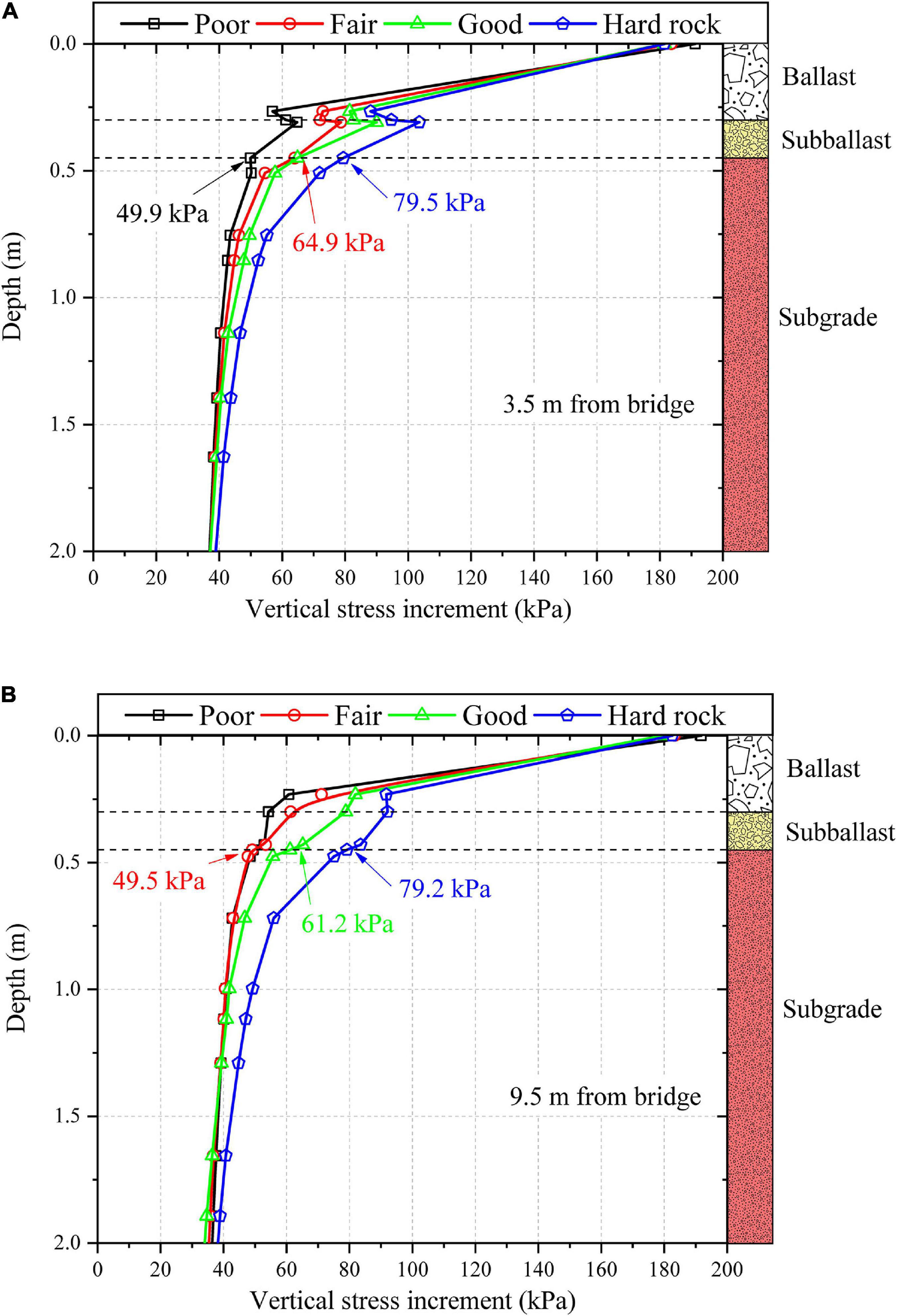
Figure 6. Variation of vertical stress increment with depth for four different subgrade types at (A): 3.5 m from the bridge; (B) 9.5 m from the bridge.
Influence of Material Plasticity
The subgrade soil is often modeled as a linear elastic material in the numerical analyses. This assumption is based on the fact that the magnitude of stresses in the subgrade layer is small due to the presence of granular layers with an adequate thickness, and therefore, limited plastic deformation can occur. To investigate the influence of material plasticity on the response of the railway track, the results of the nominal case (i.e., when the subgrade behavior is simulated using the classical Mohr-Coulomb elastic-perfectly plastic model) are compared with the case when subgrade soil is modeled as a linear-elastic material.
Figure 7 shows the variation of vertical displacement with depth for both cases (i.e., for elastic and elastoplastic material models) at 5 m away from the bridge. It can be observed that the use of elastic material model underestimates the vertical displacement in the railway track. This is attributed to the fact that the elastic material model neglects the plastic deformations generated in the subgrade soil during the train passage. It must be noted that these results are for one complete passage of the train. The plastic deformations in the subgrade soil accumulate with an increase in the number of train passages. Consequently, the difference between vertical displacements predicted using elastic and elastoplastic material model increases with an increase in the number of train passages. Therefore, the use of elastoplastic constitutive model for the subgrade soil may increase the accuracy and reliability of the predicted results.
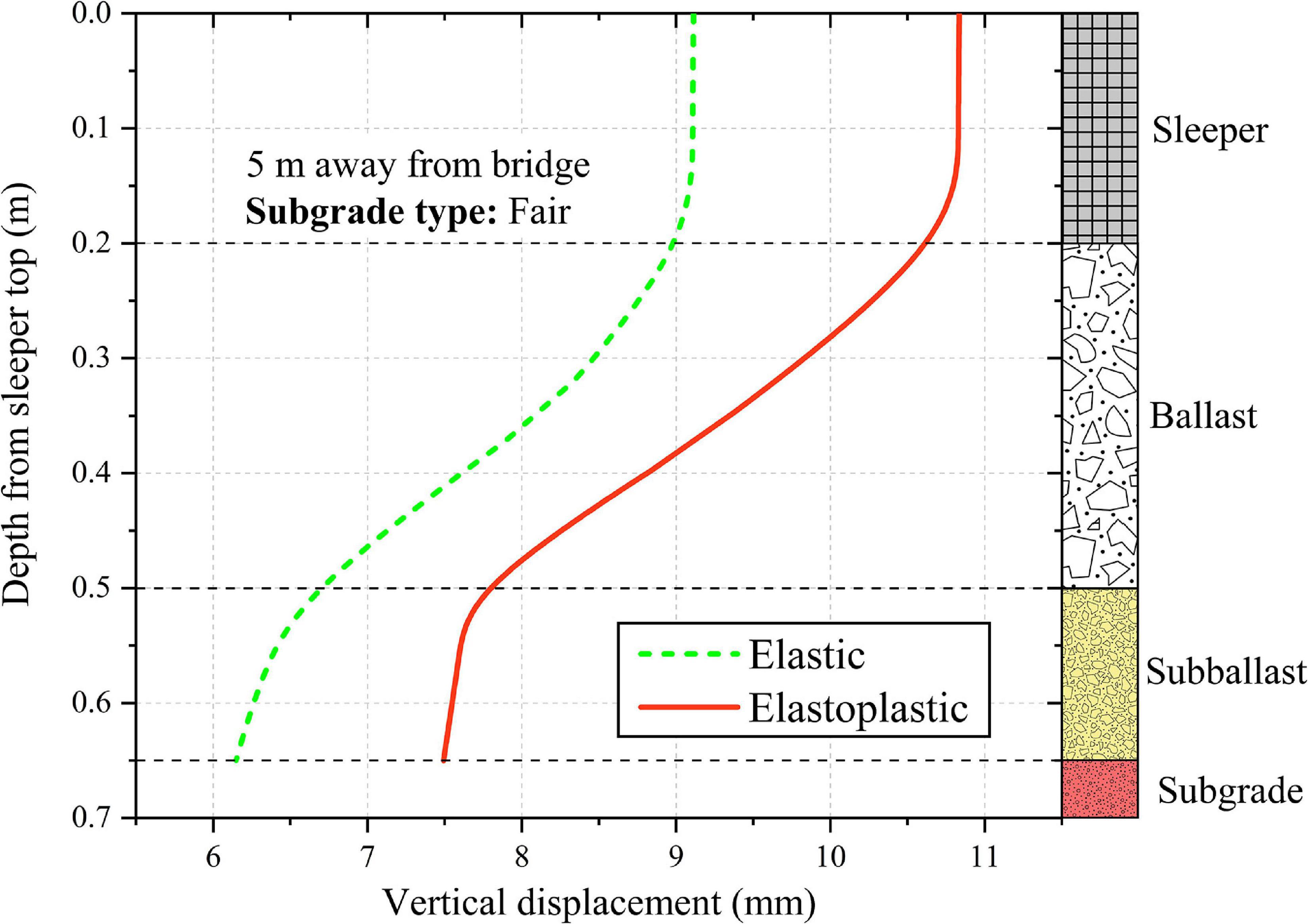
Figure 7. Variation of vertical displacement with depth predicted using elastic and elastoplastic material models for subgrade, at 5 m away from the bridge.
Assessment of the Performance of Mitigation Measures
Figure 8 shows a comparison of the track response at three different locations along the track (at the bridge, 3.5 and 9.5 m away from the bridge) for the three mitigation techniques applied in the critical zone. The results for critical zone without any mitigation measure (UR) are also shown for comparison. It can be observed that the use of wedge-shaped engineered backfill (EW) significantly reduces the track displacement near the bridge approach. The peak track displacement is reduced by 50 and 5% at 3.5 and 9.5 m from the bridge, respectively, on addition of wedge shaped engineered backfill near the bridge approach. It can also be observed that the change in track displacement is gradual, which may significantly improve the performance of the critical zone.
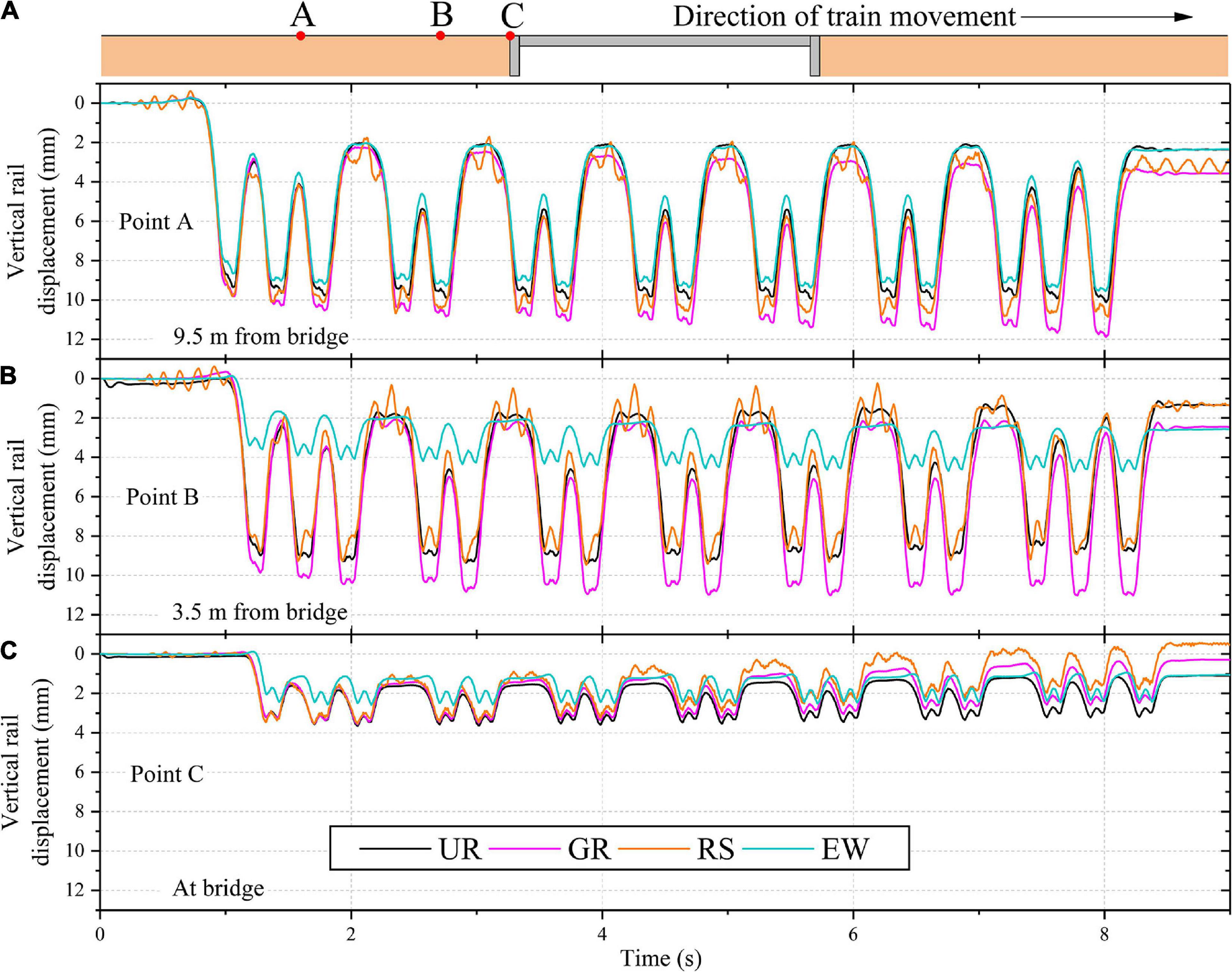
Figure 8. Variation of vertical rail displacement with time for critical zones with and without mitigation measures at: (A) 9.5 m from the bridge; (B) 3.5 m from the bridge; (C) the bridge.
The application of geogrid (GR) at the ballast-subballast interface did not improve the dynamic response of the track. The possible reason for such a behavior may be the fact that the geogrid decreases the lateral deformation of the surrounding soil. Therefore, it may be more effective along the transverse direction of the track (i.e., along the length of sleeper) as observed in previous studies (Indraratna and Nimbalkar, 2013; Jiang and Nimbalkar, 2019). However, in the present study, the track is modeled in the longitudinal direction (i.e., along the direction of train movement) and thus, the effectiveness of geogrid is not mobilized.
On reducing the sleeper spacing near the bridge approach, the track displacement slightly decreases in the vicinity of the bridge. However, the displacement away from the modified zone increases. Therefore, the reduction of sleeper spacing near the bridge approach did not improve the dynamic response of the track.
Conclusion
The present study investigated the dynamic response of the bridge-open track transition zone under moving train loads using 2D plane-strain finite element analysis. The behavior of the track layers has been simulated using elastoplastic constitutive models. The influence of subgrade properties on the performance of the critical zone is investigated. Subsequently, the effectiveness of three mitigation measures in improving the performance of the critical zone is assessed. The accuracy of the numerical model has been validated by comparing the predictions with the field data reported in the literature. A good agreement between the predicted results and literature data confirms the validity of the model. The results show that the subgrade soil significantly influences the performance of the critical zone. The difference in vertical displacement between the stiffer and softer side was considerably reduced with an increase in strength and stiffness of the subgrade soil. The accuracy of predicted results can be improved by employing an elastoplastic constitutive model instead of a linear elastic model to simulate the behavior of subgrade soils. The use of wedge-shaped engineered fill significantly improved the performance of the critical zone by providing a smooth variation of the track displacement. The use of geogrid and the reduction of sleeper spacing near the bridge approach did not significantly improve the performance of the critical zone.
Data Availability Statement
The raw data supporting the conclusions of this article will be made available by the authors, without undue reservation.
Author Contributions
SN: conceptualization, resources, and review and editing. SN, PP, and KM: methodology. PP and KM: writing original manuscript. All authors contributed to the article and approved the submitted version.
Conflict of Interest
The authors declare that the research was conducted in the absence of any commercial or financial relationships that could be construed as a potential conflict of interest.
Acknowledgments
PP acknowledges the support provided by an Australian Government Research Training Program (ARTP) Scholarship. KM acknowledges the Research computing officer, UTS for providing access to the high performance computing facility.
References
Asghari, K., Sotoudeh, S., and Zakeri, J. A. (2021). Numerical evaluation of approach slab influence on transition zone behavior in high-speed railway track. Transp. Geotech. 28:100519. doi: 10.1016/j.trgeo.2021.100519
ASTM D3999 (2011). Standard Test Methods for the Determination of the Modulus and Damping Properties of Soils Using the Cyclic Triaxial Apparatus. West Conshohocken, PA: ASTM International.
Boler, H., Mishra, D., Hou, W., and Tutumluer, E. (2018). Understanding track substructure behavior: field instrumentation data analysis and development of numerical models. Transp. Geotech. 17, 109–121. doi: 10.1016/j.trgeo.2018.10.001
Coelho, B. Z., Priest, J., and Hölscher, P. (2017). Dynamic behaviour of transition zones in soft soils during regular train traffic. Proc. Inst. Mech. Eng. F J. Rail Rapid Transit 232, 645–662. doi: 10.1177/0954409716683078
Coelho, Z. B., and Hicks, M. A. (2015). Numerical analysis of railway transition zones in soft soil. Proc. Inst. Mech. Eng. F J. Rail Rapid Transit 230, 1601–1613. doi: 10.1177/0954409715605864
Gallego, I. G., and López Pita, A. (2009). Numerical simulation of embankment—structure transition design. Proc. Inst. Mech. Eng. F J. Rail Rapid Transit 223, 331–343. doi: 10.1243/09544097jrrt234
Hall, L. (2003). Simulations and analyses of train-induced ground vibrations in finite element models. Soil Dyn. Earthq. Eng. 23, 403–413. doi: 10.1016/s0267-7261(02)00209-9
Hu, P., Zhang, C., Wen, S., and Wang, Y. (2019). Dynamic responses of high-speed railway transition zone with various subgrade fillings. Comput. Geotech. 108, 17–26. doi: 10.1016/j.compgeo.2018.12.011
Indraratna, B., and Nimbalkar, S. (2013). Stress-strain degradation response of railway ballast stabilized with geosynthetics. J. Geotech. Geoenviron. Eng. 139, 684–700. doi: 10.1061/(asce)gt.1943-5606.0000758
Jiang, Y., and Nimbalkar, S. (2019). Finite Element modeling of ballasted rail track capturing effects of geosynthetic inclusions. Front. Built Environ. 5:69. doi: 10.3389/fbuil.2019.00069
Kaewunruen, S., and Remennikov, A. M. (2007). Field trials for dynamic characteristics of railway track and its components using impact excitation technique. NDT E Int. 40, 510–519. doi: 10.1016/j.ndteint.2007.03.004
Kerr, A. D., and Moroney, B. E. (1993). Track transition problems and remedies. Proc. AREA 94, 267–298.
Li, D., and Davis, D. (2005). Transition of railroad bridge approaches. J. Geotech. Geoenviron. Eng. 131, 1392–1398. doi: 10.1061/(ASCE)1090-0241(2005)131:11(1392)
Li, L., Nimbalkar, S., and Zhong, R. (2018). Finite element model of ballasted railway with infinite boundaries considering effects of moving train loads and Rayleigh waves. Soil Dyn. Earthq. Eng. 114, 147–153. doi: 10.1016/j.soildyn.2018.06.033
Mishra, D., Boler, H., Tutumluer, E., Hou, W., and Hyslip, J. P. (2017). Deformation and dynamic load amplification trends at railroad bridge approaches. Transp. Res. Rec. 2607, 43–53. doi: 10.3141/2607-07
Nimbalkar, S., and Indraratna, B. (2016). Improved performance of ballasted rail track using geosynthetics and rubber shockmat. J. Geotech. Geoenviron. Eng. 142:04016031. doi: 10.1061/(asce)gt.1943-5606.0001491
Nimbalkar, S., Indraratna, B., Dash, S. K., and Christie, D. (2012). Improved performance of railway ballast under impact loads using shock mats. J. Geotech. Geoenviron. Eng. 138, 281–294. doi: 10.1061/(asce)gt.1943-5606.0000598
Nimbalkar, S., Punetha, P., and Kaewunruen, S. (2020). “Performance improvement of ballasted railway tracks using geocells: present state of the art,” in Geocells. Springer Transactions in Civil and Environmental Engineering, eds T. G. Sitharam, A. Hegde, and S. Kolathayar (Singapore: Springer).
Paixão, A., Alves Ribeiro, C., Pinto, N., Fortunato, E., and Calçada, R. (2014). On the use of under sleeper pads in transition zones at railway underpasses: experimental field testing. Struct. Infrastruct. Eng. 11, 112–128. doi: 10.1080/15732479.2013.850730
PLAXIS BV (2017). PLAXIS 2D Version 2017 - Finite Element Code for Soil and Rock Analysis. Delft: A.A. Balkema Publishers.
Punetha, P., and Nimbalkar, S. (2021). “Performance improvement of ballasted railway tracks for high-speed rail operations,” in Challenges and Innovations in Geomechanics, eds M. Barla, A. Di Donna, and D. Sterpi (Cham: Springer), 841–849.
Punetha, P., Nimbalkar, S., and Khabbaz, H. (2020a). Analytical evaluation of ballasted track substructure response under repeated train loads. Int. J. Geomech. 20:04020093. doi: 10.1061/(ASCE)GM.1943-5622.0001729
Punetha, P., Nimbalkar, S., and Khabbaz, H. (2020b). Evaluation of additional confinement for three-dimensional geoinclusions under general stress state. Can. Geotech. J. 57, 453–461. doi: 10.1139/cgj-2018-0866
Ribeiro, C. A., Paixão, A., Fortunato, E., and Calçada, R. (2014). Under sleeper pads in transition zones at railway underpasses: numerical modelling and experimental validation. Struct. Infrastruct. Eng. 11, 1432–1449. doi: 10.1080/15732479.2014.970203
Shahraki, M., Warnakulasooriya, C., and Witt, K. J. (2015). Numerical study of transition zone between ballasted and ballastless railway track. Transp. Geotech. 3, 58–67. doi: 10.1016/j.trgeo.2015.05.001
Stark, T. D., and Wilk, S. T. (2015). Root cause of differential movement at bridge transition zones. Proc. Inst. Mech. Eng. F J. Rail Rapid Transit 230, 1257–1269. doi: 10.1177/0954409715589620
Varandas, J. N., Hölscher, P., and Silva, M. A. G. (2016). Three-dimensional track-ballast interaction model for the study of a culvert transition. Soil Dyn. Earthq. Eng. 89, 116–127. doi: 10.1016/j.soildyn.2016.07.013
Wang, H., Markine, V., and Liu, X. (2018). Experimental analysis of railway track settlement in transition zones. Proc. Inst. Mech. Eng. F J. Rail Rapid Transit 232, 1774–1789. doi: 10.1177/0954409717748789
Keywords: railway track, transition zone, geotechnical model, geosynthetics, vertical displacement, moving load, subgrade
Citation: Punetha P, Maharjan K and Nimbalkar S (2021) Finite Element Modeling of the Dynamic Response of Critical Zones in a Ballasted Railway Track. Front. Built Environ. 7:660292. doi: 10.3389/fbuil.2021.660292
Received: 29 January 2021; Accepted: 15 March 2021;
Published: 09 April 2021.
Edited by:
Sakdirat Kaewunruen, University of Birmingham, United KingdomReviewed by:
Jabbar-Ali Zakeri, Iran University of Science and Technology, IranTing Li, Southwest Jiaotong University, China
Copyright © 2021 Punetha, Maharjan and Nimbalkar. This is an open-access article distributed under the terms of the Creative Commons Attribution License (CC BY). The use, distribution or reproduction in other forums is permitted, provided the original author(s) and the copyright owner(s) are credited and that the original publication in this journal is cited, in accordance with accepted academic practice. No use, distribution or reproduction is permitted which does not comply with these terms.
*Correspondence: Sanjay Nimbalkar, c2FuamF5Lm5pbWJhbGthckB1dHMuZWR1LmF1