 Kohei Fujita
 Ryota Wataya
 Izuru Takewaki
- Department of Architecture and Architectural Engineering, Graduate School of Engineering, Kyoto University, Kyoto, Japan
A new robust method for optimal damper placement is presented for building structures under the critical double impulse. Oil dampers are treated here as representative supplemental dampers to control the seismic response of high-rise buildings. Such oil dampers usually obey a bi-linear force-velocity relation in controlling the maximum damping force through a relief mechanism to avoid the occurrence of excessive design forces in surrounding frames. The influence of uncertainty in characteristics of those bi-linear oil dampers on building structural safety is investigated. For the efficient evaluation of dynamic performance, the resonant critical double impulse is used as the base input instead of actual earthquake ground motions. Since the critical double impulse is determined to maximize the input energy to the objective building by changing the second impulse timing, uncertainties in input ground motions can be taken into account in a robust manner. To consider these various uncertainties, the robustness function based on the Info-Gap model is used in the robust optimization to assess structural performance variations caused by various uncertainties in the structural design phase. In this paper, a new innovative objective function in the robust optimal damper placement problem is proposed to enhance the robustness of structural performance under the variation of structural parameters by comparing the robustness function of the robust design with that of an ordinary optimal damper placement without considering uncertainties. Numerical examples of the robust optimal design of linear and bi-linear oil damper placements are shown for 10-story and 20-story planar building frame models. Structural performances of the robust optimal design to the conventional design earthquake ground motions are examined to investigate the validity of using the critical double impulse in the structural design under uncertainties.
Introduction
As characteristics of earthquake ground motions are clarified rapidly, e.g., large-amplitude ground motions, long-period long-duration ground motions, design methods for building structures with supplemental dampers have entered into a new era in the earthquake-prone countries. The smart building structural design using such supplemental dampers is aimed at efficiently improving the structural damping performance under specified constraints, e.g., a constant cost constraint on dampers, the maximum local response constraints. In the evaluation of dynamic performances of building structures to earthquake ground motions, the maximum dynamic response, such as the maximum interstory drift, is usually used to clarify the structural safety. In order to satisfy such structural performance requirements, various researches and practical applications have been conducted so far. Examples are the development of high-performance damping systems using nonlinear dampers and their installation as shown in Hahn and Sathiavageeswaran (1992), Lopez and Soong (2002), Martinez-Rodrigo and Romero (2003), Silvestri et al. (2010), Pnevmatikos (2012), Adachi et al. (2013), Lang et al. (2013), Lavan and Avishur (2013), Fujita et al. (2014), Hatzigeorgiou and Pnevmatikos (2014), Palermo et al. (2017), Parcianello et al. (2017), Pollini et al. (2017), Akcelyan et al. (2018), De Domenico and Ricciardi (2019), De Demenico et al. (2019), and Idels and Lavan (2020). These researches on the design theory for efficient damper placement can be categorized as the optimal damper allocation problem. However, the design goals of most optimal damper allocation studies have been focused on minimizing the specified maximum structural performance without considering uncertainties in input excitations and damping performances.
It is well known that damper performances or properties, such as rubber isolators for base-isolation and oil dampers for structural control, can be varied due to various uncertainties such as temperature dependency, aging deterioration and manufacturing error, etc. In order to investigate the influence of these structural uncertainties on the seismic structural performance, many researches on uncertainty analysis methods have been accumulated, e.g., Ben-Haim and Elishakoff (1990), Elishakoff and Ohsaki (2010), Takewaki and Ben-Haim (2005), Henriques et al. (2008), Fujita and Takewaki (2011), and Fujita et al. (2017). The uncertainty analysis can be defined as a method for deriving the upper bound of responses for a given uncertainty model and some efficient methods have been proposed to estimate the upper and lower bounds of objective functions. For examples, the interval analysis method is one of the traditional uncertain analysis methods where uncertain variables are assumed to be given in terms of interval parameters with lower and upper boundaries. Historically various interval analysis techniques have been proposed based on the interval arithmetic algorithm (Dong and Shah, 1987; Rao and Berke, 1997; Chen et al., 2002; Qiu, 2003; Chen et al., 2003; Chen and Wu, 2004; Moens and Vandepitte, 2004; Chen et al., 2009; Moens and Hanns, 2011).
In order to enhance the robustness of structures to uncertainties and develop the structural design methodology considering such robustness, a robust optimization problem has been proposed where the design objective is to minimize the variability of the structural performance caused by input and structural uncertainties. For evaluating the robustness of structural performance, Ben-Haim (2001) has introduced the robustness function based on the Info-Gap decision theory. In the Info-Gap model, uncertain parameters are defined by a non-probabilistic model and are called interval parameters. Fujita and Takewaki (2012) compared the robustness of building structures with various passive damper placements based on the evaluation of robustness functions using the uncertainty analysis called the URP method.
In this paper, a new robust method for optimal damper placement is presented for building structures with linear and bi-linear oil dampers. The nominal structural performance evaluated by the response analysis without considering uncertainties is a general goal of the ordinary structural optimization. However, it is concerned whether this nominal structural performance may become worse at the expense of enhancing the robustness compared with the conventional ordinary optimal design without considering uncertainties. The proposed robust optimization method is aimed at not only increasing the robustness of structural performance with respect to the uncertainty level but also preventing the deterioration of the nominal structural performance. The objective function of the robust optimization is defined by comparing the robustness function of the robust design with that of the ordinary optimal design. The damping properties, i.e., the damping coefficients of linear oil dampers and the maximum allowable damping forces of bi-linear oil dampers, and the story shear stiffnesses are assumed to be uncertain. Numerical examples of the proposed robust optimal damper design are presented for 10-story and 20-story planar building frame models.
Evaluation of Robustness Using Uncertainty Analysis
In a conventional structural design, it is needed to satisfy structural performance demands under a specified design loading such as equivalent static forces corresponding to earthquake ground motions. In this case, structural uncertainties, e.g., variations of stiffness and damping coefficients of structural members, are often neglected. However, a certain variability of performance characteristics exists in vibration control components, such as various dampers and base isolators, installed to buildings to reduce the input energy transition to structural members. An evaluation index is needed to consider the influence of these structural uncertainties on the performance variation in the structural design. The robustness in the building structural design is one of such evaluation indices, and can be defined as the insensitivity of the structural performance with respect to input and structural uncertainties.
In order to evaluate the robustness of the structural performance quantitatively, the robustness function has been proposed based on the info-gap model (Ben-Haim, 2001) where the variations of parameters are usually given by upper and lower bounds known as interval parameters. In this paper, we assume that the interval parameter
where
According to the info-gap model, the robustness function
where
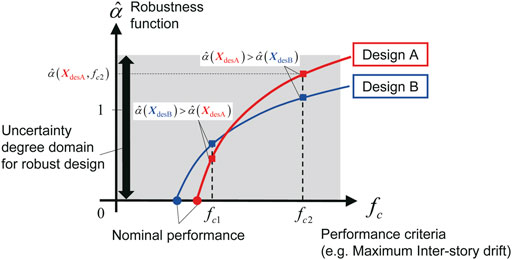
FIGURE 1. Comparison of robustness functions for different designs.
For the efficient evaluation of the robustness function, we solve the following anti-optimization problem with various variations represented by the uncertainty coefficient
In the constraint of the optimization problem expressed by Eq. 3, the interval domain of uncertain parameters is varied by
Figure 2 shows the flowchart and diagram for evaluating the robustness function. First, the discrete degree
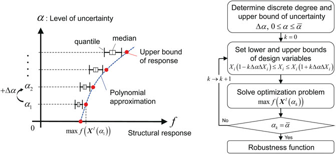
FIGURE 2. Schematic diagram and flowchart for evaluation of robustness function.
Ordinary and Robust Optimal Damper Design Problems
Ordinary Optimization Problem of Damper Placement for Linear Oil Damper
In order to solve a general optimization problem, we need to define an objective function to be minimized and constraint conditions. The ordinary optimal damper design problem for the damped building is to find the damping coefficients of dampers so as to minimize the maximum interstory drift for a specified sum of damping coefficients of dampers. The optimal damper design problem using linear oil dampers can be described as
where
In the structural design process, the structural response demand as the design goal is usually given first. Therefore, in order to obtain the suitable optimal damping coefficients for satisfying this design demand, it is necessary to change the value of the total damping coefficient under the constraint condition in Eq. 4. On the other hand, by exchanging the objective function and the constraint condition, the ordinary optimal damper placement for linear oil dampers without considering uncertainties can be derived by solving the following problem defined as
where
Ordinary Damper Optimization Problem for Bi-linear Oil Damper
It is known that the damping force of oil dampers is usually limited so that the damping force does not exceed a certain level by the relief mechanism. When the interstory velocity exceeds the relief velocity, the damping coefficient decreases. In the modeling of non-linear oil dampers with the relief mechanism, the damping force characteristics are usually analyzed by using the bi-linear model. Since the cost of non-linear oil dampers depends on the maximum allowable damping force rather than the damping coefficient, the objective function in the optimization problem for bi-linear oil dampers is to minimize the sum of the maximum allowable damping forces. The ordinary optimal damper placement problem for bi-linear oil dampers can be defined as
where
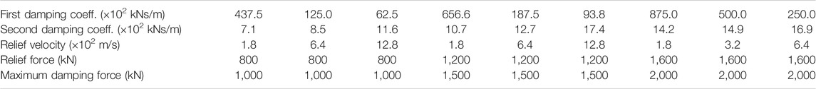
TABLE 1. Example of bi-linear oil damper property.
Conventional Damper Optimization Problem and Multi-Objective Robust Damper Optimization Problem
Conventional robust optimization problems for seismic design may be generally aimed at minimizing the structural performance variability under the consideration of various uncertainties, e.g., variability in input ground motion characteristics and structural parameters, etc. Applying the robustness function for assessing the degree of performance variability to the robust optimization problem, it is natural to assume that increasing the value of the robustness function is one of the objective functions in the optimization. However, since the robustness function
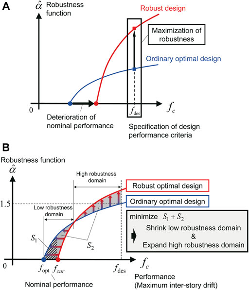
FIGURE 3. Conventional and proposed robust optimization problems, (A) Conventional robust optimization problem: Maximization of robustness function, (B) Proposed robust optimization problem: Multi-objective optimization.
In order to prevent the deterioration of the nominal structural response, corresponding to
As shown in Figure 3B, the robustness function value of the robust optimal solution should be larger in the part of the performance criterion domain compared with the robustness function value of the ordinary optimal solution. Therefore, there should be intersections where the robustness function values are the same in the comparison of the ordinary optimal design and the robust optimal design. From the viewpoint of performance comparison with the ordinary optimal design, a difference domain of the robustness functions can be defined as an objective function for the robust optimization problem using linear oil dampers or non-linear oil dampers described as
where
In this paper, the variation of elastic shear stiffness induced by model uncertainties is also considered along with damping characteristics uncertainties. As for the uncertainties of oil damper, it is assumed that the maximum damping force of both linear and bi-linear oil dampers varies due to the variation of product as shown in Figure 4. For linear oil dampers, the damping coefficient
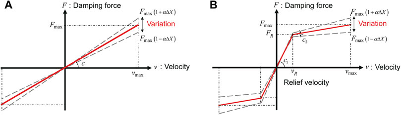
FIGURE 4. Uncertainty in maximum damping force of oil dampers, (A) Linear oil damper, (B) Bi-linear oil damper.
Figure 5 shows the flowchart of the proposed robust optimization problem. First, the ordinary optimal damper design for a specified structural performance is derived. By applying the uncertainty analysis to the ordinary optimal damper design, the robustness function
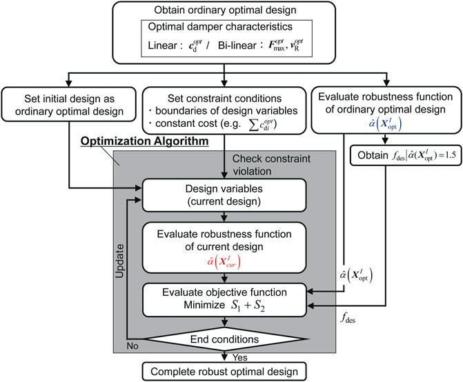
FIGURE 5. Flowchart for solving proposed robust optimization problem.
Numerical Examples
In this section, the proposed robust optimal design method of nonlinear dampers is applied to 10-story and 20-story building models. Numerical examples are presented according to the flowchart shown in Figure 6. In Figure 6, a summary of the results for each analysis is also provided.
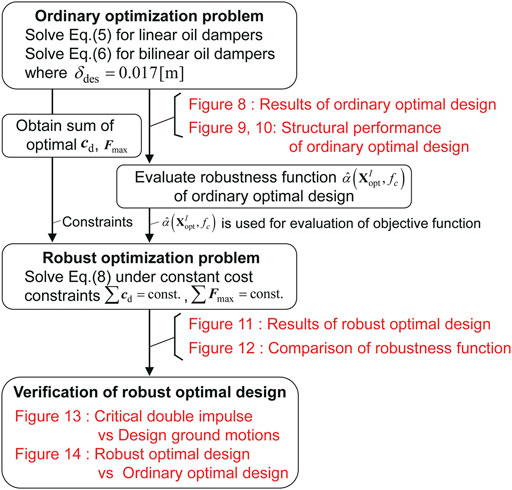
FIGURE 6. Flowchart for numerical example and presented results for each analysis.
Building Models
Since the evaluation of the robustness function for planar frame models needs much time, simplified lumped-mass shear building models, i.e.,
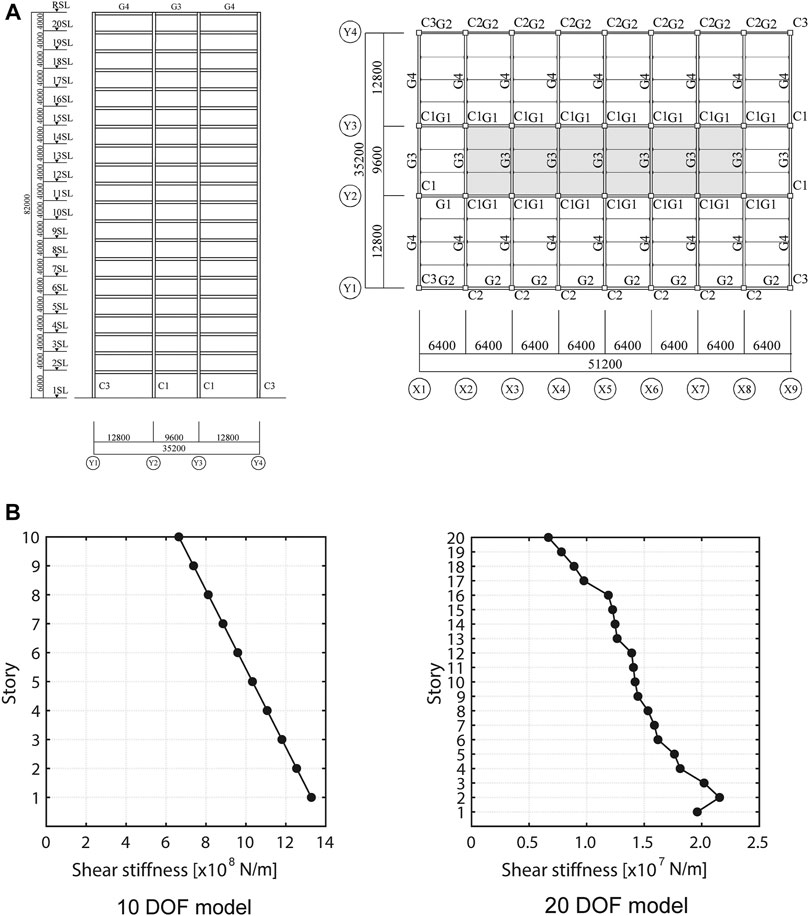
FIGURE 7. Example building frame, (A) Plan and elevation of 20-story building frame, (B) Story shear stiffness distributions of 10 DOF and 20 DOF building models.
Determination of Amplitude of Critical Double Impulse
The critical double impulse consisting of two inversely-directed impulses with the same velocity amplitude has been proposed by Kojima and Takewaki (2015) for the evaluation of the upper bound of elastic-plastic building responses under pulse-type ground motions. This can be easily used as the input excitation to MDOF building models in the time-history response analysis, since it is also easy to find the critical impulse timing (Akehashi and Takewaki, 2019; Tamura et al., 2019; Akehashi and Takewaki, 2020). Compared with conventional design earthquake ground motions such as actually recorded earthquake ground motions and artificial seismic waves, the input critical to building structures is used in this critical double impulse. Since the second impulse timing of the critical double impulse can be automatically determined so that the input energy to the building is maximized, the input uncertainties can be implicitly taken into account. This is because the critical double impulse as a substitute for near-fault ground motions can be regarded as the critical excitation to the objective building. In this paper, instead of using specific design earthquake ground motions, the critical double impulse is used for evaluating the seismic structural performance. In order to discuss the relationship of the input amplitude between the critical double impulse and the design ground motions, the velocity amplitude of impulse is evaluated by referring to the seismic response of the objective building without damper subjected to the design ground motions. By changing the velocity amplitude
El Centro NS (1940), Taft EW (1952), Hachinohe NS (1968) are adopted as the design ground motions. The maximum velocity amplitude of these design ground motions is scaled to 0.25[m/s] as specified as the design ground motions of level 1 in the Building Standard Law in Japan. In this case, the maximum interstory drift angle should be smaller than 1/200. Following the above-mentioned criterion, the velocity amplitudes of the critical double impulses are set to 0.414[m/s] for the 10-DOF model, and to 0.339[m/s] for the 20-DOF model, respectively.
Ordinary Optimal Damper Placement
As shown in the ordinary problem of optimal damper placement defined in Eqs. 5, 6, the sum of damping coefficients of linear oil dampers and the sum of the maximum damping forces in bi-linear oil dampers are minimized without the variability of damper properties for the given performance criterion. The seismic performance criterion
Figure 8 shows the distributions of damping coefficients of linear oil dampers, and the maximum allowable damping force and relief velocity distributions of bi-linear oil dampers in the ordinary optimal damper placement problem without considering uncertainties. The optimization solver based on the quadratic programming algorithm provided by MATLAB® is applied for the optimization procedure in this paper.
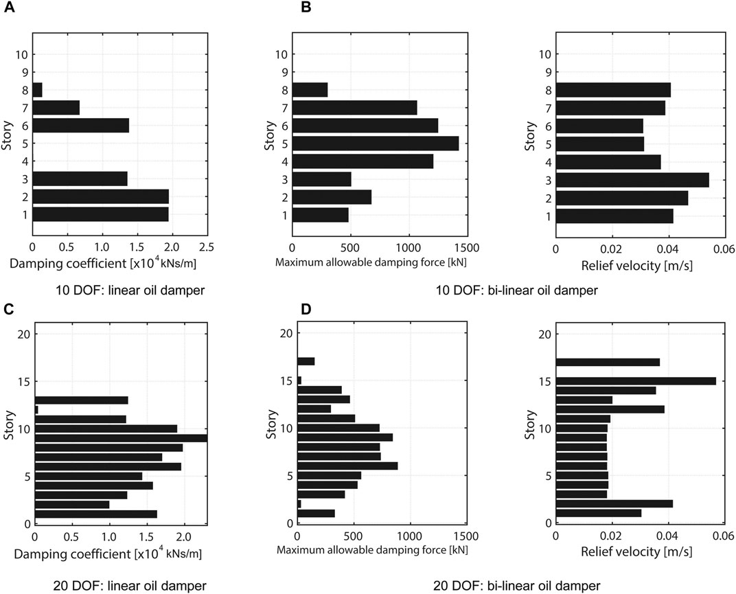
FIGURE 8. Optimal damper characteristics for ordinary problem without uncertainties (Damping coefficient for linear oil damper, Maximum allowable damping force and relief velocity for bi-linear oil damper).
Figure 9 presents the maximum interstory drift distribution for linear and bi-linear oil dampers and includes the comparison with the response of the frame without damper. It can be confirmed that the maximum interstory drifts at several floors coincide with the constraint limit
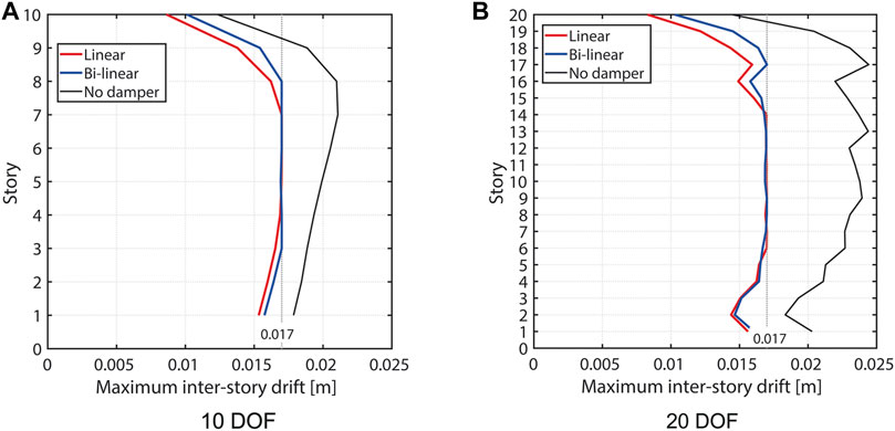
FIGURE 9. Maximum interstory drift distribution.
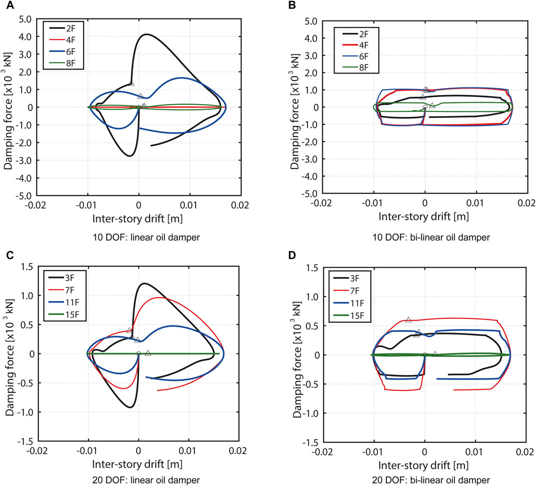
FIGURE 10. Damping force-interstory drift relations of models designed for linear oil damper and bi-linear oil damper using ordinary optimal design method.
Robust Optimal Damper Placement
The variability of damping coefficients of oil dampers is officially allowable in the Building Standard Law in Japan. As explained in Conventional Damper Optimization Problem and Multi-Objective Robust Damper Optimization Problem, the damping force variability can occur in both linear and bi-linear oil dampers due mainly to randomness of realization. On the other hand, we assume that the variability of shear stiffness corresponds mainly to the modelling error between the actual building and the planar frame model. Therefore, the structural uncertainties in the robust design problem are considered in both the damper characteristics and the story shear stiffnesses of the main frame. For the mathematical formulation, the uncertain parameters are given by interval variables as shown in Eq. 1. When the degree of uncertainty
Since the issue on the initial design that affects the optimization convergence exists in the SQP method, the ordinary optimal damper placements derived in Figure 8 are used as the initial design in the robust optimization using the SQP method. On the other hand, the initial design set in the GA is randomly generated considering lower and upper bounds of design variables. However, since the sum of damping coefficients or the sum of the maximum allowable damping forces is limited in the constraint of the robust optimization, it is difficult to generate the initial design set automatically. Furthermore, when the nominal performances of the initial design set are worse than
Figure 11 shows the robust optimal damper characteristics derived in the proposed multi-objective robust optimization problem for linear and bi-linear oil dampers formulated in Eq. 8. Since the sum of damping coefficients for the linear oil dampers or the sum of the maximum allowable damping forces for the bi-linear oil damper is the same as that for the ordinary optimal damper placement shown in Figure 8, the optimum value in the robust optimal design increases or decreases in each story compared to the normal optimal design. In the robust optimal design of 20 DOF models with bi-linear oil dampers, the difference of the robust optimal design value from that of the ordinary optimal design is small. This is probably because the optimization end constraints on the change in the objective function were relaxed compared with other cases from the view point of reducing the computational time.
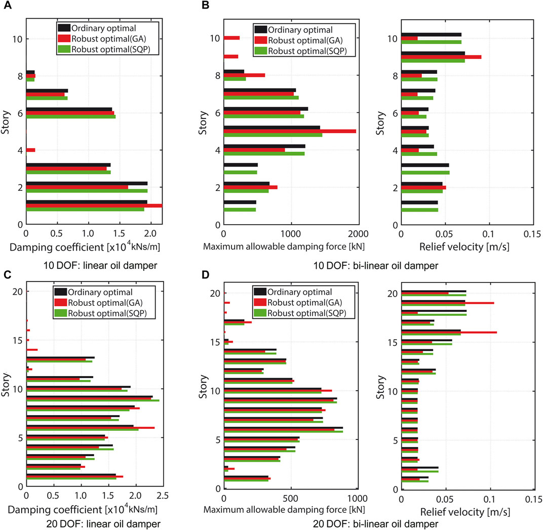
FIGURE 11. Ordinary optimal damper distribution and robust optimal damper distribution for 10 and 20-story buildings (Damping coefficient for linear oil damper, Maximum allowable damping force and relief velocity for bi-linear oil damper).
In order to evaluate the difference of the robustness function of the target building model with that of the optimal damper placements, the robustness functions of the ordinary optimal damper placement and the robust optimal damper placement derived by the SQP method and GA are compared in Figure 12. In these figures, the black circle, red rhombus and blue square markers represent the actual response evaluation values by uncertainty analysis. The robustness function of each design has been derived by the polynomial approximation, and the difference of the robustness functions is used as the objective function of the robust optimization. As seen in these figures, the proposed robust damper placements have higher robustness than the ordinary optimal solutions. In addition, the deterioration of the performance value at
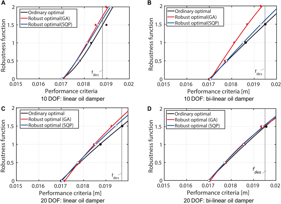
FIGURE 12. Comparison of robustness functions for robust optimal damper placement with that for ordinary optimal damper placement.
Verification of Proposed Robust Optimal Damper Placement to Design Ground Motions
In this paper, the critical double impulse was used in the optimization procedure instead of specified design ground motions. In this section, in order to investigate the validity of the proposed robust optimal damper placement using the critical double impulse for various design ground motions, the robustness functions for the optimal damper placement under the design ground motions are investigated. These robustness functions were derived by the SQP method as shown in Figure 12. The robustness functions can be derived by replacing the critical double impulse with the design ground motions.
Figure 13 shows the comparison of the robustness functions for the ordinary optimal designs without considering uncertainties and those for the robust optimal designs. The amplitudes of the critical double impulse were determined so that the maximum interstory drift of the frame without dampers (See Determination of Amplitude of Critical Double Impulse) was the same as that to the design ground motions. It can be confirmed that the design demands on the interstory drift are satisfied for most of design earthquake ground motions by optimizing the damper placement for the critical double impulse.
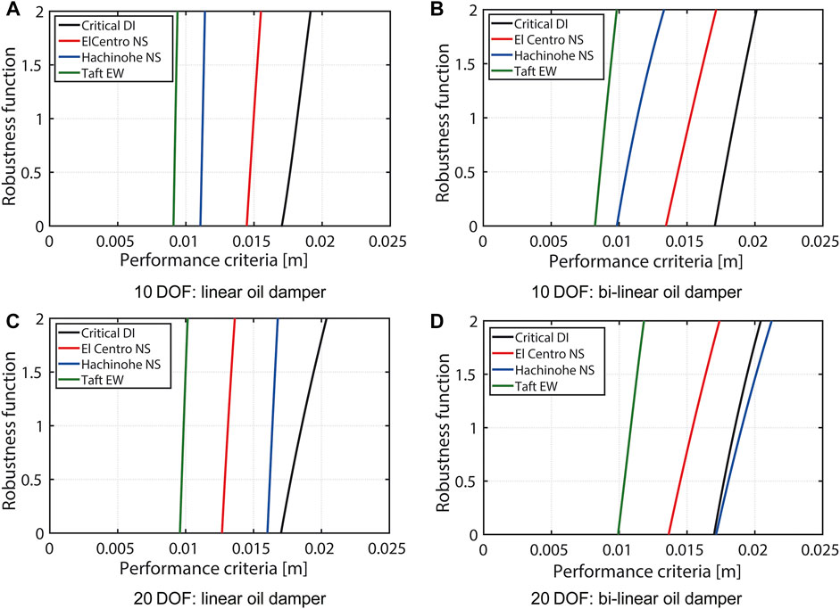
FIGURE 13. Comparison of robustness functions for ordinary optimal damper placement and robust optimal damper placement under critical double impulse and design ground motions.
Figure 14 presents a comparison of the damping force characteristics of the damper at
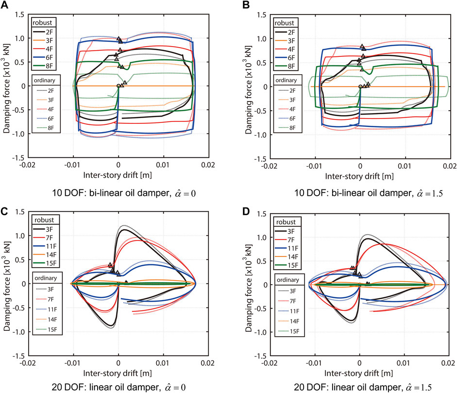
FIGURE 14. Damping force-interstory drift relations of models designed for linear oil damper and bi-linear oil damper using proposed robust optimal design method (case without uncertainty
Conclusion
The robust optimal design of linear and bi-linear oil dampers has been presented based on the robustness function for building structures under the uncertainties of structural parameters. The uncertainties in damper characteristics of linear and bilinear oil dampers and stiffness of the building frame have been dealt with in this paper. A method using the robustness function derived by the sequential uncertainty analysis was applied to evaluate the robustness of the building frame with linear and bilinear supplemental dampers under various uncertainties, e.g., shear stiffness and damping coefficient of supplemental oil dampers. The robust design has been obtained by maximizing the proposed objective function where the difference is treated as a principal parameter between the robustness function of the target design and that of the ordinary optimal design without considering uncertainties. The robust design approach presented in this paper was aimed not only at enhancing the robustness of structural performances but also preventing the deterioration of the nominal structural performance.
The critical double impulse as the excitation to buildings has been used to evaluate the maximum interstory drift in the worst-case scenario. The critical double impulse has overcome a difficulty in computational loads. The worst-case scenario can be automatically set in the structural response of nonlinear supplemental dampers and it has been confirmed through numerical examples that the optimal design is valid for other ordinary seismic inputs. The amplitude of the double impulse was determined by calculating the maximum seismic response of the bare building model without damper subjected to actual design earthquake ground motions.
Comparative studies on the robust optimal damper placement using linear and bilinear oil dampers have been investigated through numerical examples for 10-story and 20-story planer building frames. Since the robust optimal design problem has two aspects; one is the minimization of the seismic response such as the interstory drift and another is to find the worst variation of uncertain parameters that maximizes the seismic response, the computational load of the robust optimization is too heavy for the models with large degree of freedom such as building frame models. Equivalent multi-degree-of-freedom shear building models have then been used for the robust optimization. It has been shown that the robustness of the structural performance can be improved in the proposed robust optimal damper placement compared with the ordinary optimal damper placement without considering uncertainties.
For future work, it is needed to discuss how to determine the actual positioning of dampers in two-dimensional or three-dimensional frame structures from the results of the optimal design derived by using the equivalent simplified shear model.
Data Availability Statement
The original contributions presented in the study are included in the article/Supplementary Material, further inquiries can be directed to the corresponding author.
Author Contributions
KF contributed to the design of the research, and wrote the first draft of the manuscript. RW performed the numerical simulations. IT advised the research problem and revised the manuscript. All authors contributed to manuscript revision, read, and approved the submitted version.
Funding
Part of the present work is supported by the Grant-in-Aid for Scientific Research (KAKENHI) of Japan Society for the Promotion of Science (18H01584). This support is greatly appreciated.
Conflict of Interest
The authors declare that the research was conducted in the absence of any commercial or financial relationships that could be construed as a potential conflict of interest.
Publisher’s Note
All claims expressed in this article are solely those of the authors and do not necessarily represent those of their affiliated organizations, or those of the publisher, the editors and the reviewers. Any product that may be evaluated in this article, or claim that may be made by its manufacturer, is not guaranteed or endorsed by the publisher.
References
Adachi, F., Yoshitomi, S., Tsuji, M., and Takewaki, I. (2013). Nonlinear Optimal Oil Damper Design in Seismically Controlled Multi-story Building Frame. Soil Dyn. Earthquake Eng. 44, 1–13. doi:10.1016/j.soildyn.2012.08.010
Akcelyan, S., Lignos, D. G., and Hikino, T. (2018). Adaptive Numerical Method Algorithms for Nonlinear Viscous and Bilinear Oil Damper Models Subjected to Dynamic Loading. Soil Dyn. Earthquake Eng. 113, 488–502. doi:10.1016/j.soildyn.2018.06.021
Akehashi, H., and Takewaki, I. (2020). Comparative Investigation on Optimal Viscous Damper Placement for Elastic-Plastic MDOF Structures: Transfer Function Amplitude or Double Impulse. Soil Dyn. Earthquake Eng. 130, 105987. doi:10.1016/j.soildyn.2019.105987
Akehashi, H., and Takewaki, I. (2019). Optimal Viscous Damper Placement for Elastic-Plastic MDOF Structures under Critical Double Impulse. Front. Built Environ. 5, 20. doi:10.3389/fbuil.2019.00020
Ben-Haim, Y., and Elishakoff, I. (1990). Convex Models of Uncertainty in Applied Mechanics. New York: Elsevier.
Chen, S. H., Lian, H., and Yang, X. (2003). Interval Eigenvalue Analysis for Structures with Interval Parameters. Finite Elem. Anal. Des. 39 (5-6), 419–431. doi:10.1016/S0168-874X(02)00082-3
Chen, S. H., Lian, H., and Yang, X. (2002). Interval Static Displacement Analysis for Structures with Interval Parameters. Int. J. Numer. Meth. Eng. 53, 393–407. doi:10.1002/nme.281
Chen, S. H., Ma, L., Meng, G. W., and Guo, R. (2009). An Efficient Method for Evaluating the Natural Frequency of Structures with Uncertain-But-Bounded Parameters. Comp. Struct. 87, 582–590. doi:10.1016/j.compstruc.2009.02.009
Chen, S. H., and Wu, J. (2004). Interval Optimization of Dynamic Response for Structures with Interval Parameters. Comp. Struct. 82, 1–11. doi:10.1016/j.compstruc.2003.09.001
De Domenico, D., and Ricciardi, G. (2019). Earthquake protection of Structures with Nonlinear Viscous Dampers Optimized through an Energy-Based Stochastic Approach. Eng. Struct. 179, 523–539. doi:10.1016/j.engstruct.2018.09.076
De Domenico, D., Ricciardi, G., and Takewaki, I. (2019). Design Strategies of Viscous Dampers for Seismic protection of Building Structures: A Review. Soil Dyn. Earthq. Eng. 118, 144–165. doi:10.1016/j.soildyn.2018.12.024
Dong, W., and Shah, H. (1987). Vertex Method for Computing Functions of Fuzzy Variables. Fuzzy Set. Sys. 24 (1), 65–78. doi:10.1016/0165-0114(87)90114-X
Elishakoff, I., and Ohsaki, M. (2010). Optimization and Anti-optimization of Structures under Uncertainty. London: Imperial College Press.
Fujita, K., Kasagi, M., Lang, Z. Q., Guo, P. F., and Takewaki, I. (2014). Optimal Placement and Design of Nonlinear Dampers for Building Structures in the Frequency Domain. Earthq. Struct. 7 (6), 1025–1044. doi:10.12989/eas.2014.7.6.1025
Fujita, K., and Takewaki, I. (2011). An Efficient Methodology for Robustness Evaluation by Advanced Interval Analysis Using Second-Order Taylor Series Expansion. Eng. Struct. 33 (12), 3299–3310. doi:10.1016/j.engstruct.2011.08.029
Fujita, K., and Takewaki, I. (2012). Robust Passive Damper Design for Building Structures under Uncertain Structural Parameter Environments. Earthq. Struct. 3 (6), 805–820. doi:10.12989/eas.2012.3.6.805
Fujita, K., Yasuda, K., Kanno, Y., and Takewaki, I. (2017). Robustness Evaluation of Elastoplastic Base-Isolated High-Rise Buildings Subjected to Critical Double Impulse. Front. Built Environ. 3, 31. doi:10.3389/fbuil.2017.00031
Fujita, K., and Yasuda, K. (2016). Robust Optimization for Damper Placement under Structural Uncertainties Using Robustness Function, J. Struct. Eng., 62, 387–394.
Hahn, G. D., and Sathiavageeswaran, K. R. (1992). Effects of Added-Damper Distribution on the Seismic Response of Buildings. Comp. Struct. 43 (5), 941–950. doi:10.1016/0045-7949(92)90308-M
Hatzigeorgiou, G. D., and Pnevmatikos, N. G. (2014). Maximum Damping Forces for Structures with Viscous Dampers under Near-Source Earthquakes. Eng. Struct. 68 (1), 1–13.
Henriques, A. A., Veiga, J. M. C., Matos, J. A. C., and Delgado, J. M. (2008). Uncertainty Analysis of Structural Systems by Perturbation Techniques. Struct. Multidisciplinary Optimization 35 (3), 201–212. doi:10.1007/s00158-007-0218-z
Idels, O., and Lavan, O. (2020). Optimization Based Seismic Design of Steel Moment Resisting Frames with Nonlinear Viscous Dampers. Struct. Control. Health Monit. 28 (1), e2655. doi:10.1002/stc.2655
Kojima, K., Fujita, K., and Takewaki, I. (2015). Critical Double Impulse Input and Bound of Earthquake Input Energy to Building Structure. Front. Built Environ. 1, 5. doi:10.3389/fbuil.2015.00005
Lang, Z. Q., Guo, P. F., and Takewaki, I. (2013). Output Frequency Response Function Based Design of Additional Nonlinear Viscous Dampers for Vibration Control of Multi-Degree-Of-freedom Systems. J. Sound Vib. 332 (19), 4461–4481. doi:10.1016/j.jsv.2013.04.001
Lavan, O., and Avishur, M. (2013). Seismic Behavior of Viscously Damped Yielding Frames under Structural and Damping Uncertainties. Bull. Earthq. Eng. 11, 2309–2332. doi:10.1007/s10518-013-9479-7
Lopez Garcia, D., and Soong, T. T. (2002). Efficiency of a Simple Approach to Damper Allocation in MDOF Structures. J. Struct. Control. 9, 19–30. doi:10.1002/stc.3
Martinez-Rodrigo, M., and Romero, M. L. (2003). An Optimum Retrofit Strategy for Moment Resisting Frames with Nonlinear Viscous Dampers for Seismic Applications. Eng. Struct. 25 (7), 913–925. doi:10.1016/S0141-0296(03)00025-7
Moens, D., and Hanns, M. (2011). Non-probabilistic Finite Element Analysis for Parametric Uncertainty Treatment in Applied Mechanics: Recent Advances. Finite Elem. Anal. Des. 47 (1), 4–16. doi:10.1016/j.finel.2010.07.010
Moens, D., and Vandepitte, D. (2004). An Interval Finite Element Approach for the Calculation of Envelope Frequency Response Functions. Int. J. Num. Meth. Eng. 61 (14), 2480–2507. doi:10.1002/nme.1159
Okada, T., Fujita, K., and Takewaki, I. (2016). Robustness Evaluation of Seismic Pile Response Considering Uncertainty Mechanism of Soil Properties, J. Innovative Infra. Solutions 1 (1), 1–14. doi:10.1007/s41062-016-0009-8
Palermo, M., Silvestri, S., Gasparini, G., Dib, A., and Trombetti, T. (2017). A Direct Design Procedure for Frame Structures with Added Viscous Dampers for the Mitigation of Earthquake-Induced Vibrations. Proced. Eng 199, 1755–1760. doi:10.1016/j.proeng.2017.09.441
Parcianello, E., Chisari, C., and Amadio, C. (2017). Optimal Design of Nonlinear Viscous Dampers for Frame Structures. Soil Dyn. Earthq. Eng. 100, 257–260. doi:10.1016/j.soildyn.2017.06.006
Pnevmatikos, N. G. (2012). New Strategy for Controlling Structures Collapse against Earthquakes. Nat. Sci. 4, 667–676. doi:10.4236/ns.2012.428088
Pollini, N., Lavan, O., and Amir, O. (2017). Minimum-cost Optimization of Nonlinear Fluid Viscous Dampers and Their Supporting Members for Seismic Retrofitting. Earthq. Eng. Struct. Dyn. 46 (12), 1941–1961. doi:10.1002/eqe.2888
Qiu, Z. P. (2003). Comparison of Static Response of Structures Using Convex Models and Interval Analysis Method. Int. J. Numer. Meth. Eng. 56 (12), 1735–1753. doi:10.1002/nme.636
Rao, S. S., and Berke, L. (1997). Analysis of Uncertain Structural Systems Using Interval Analysis. AIAA J. 35, 727–735. doi:10.2514/2.164
Silvestri, S., Gasparini, G., and Trombetti, T. (2010). A Five-step Procedure for the Dimensioning of Viscous Dampers to Be Inserted in Building Structures. J. Earthq. Eng. 14 (3), 417–447. doi:10.1080/13632460903093891
Takewaki, I., and Ben-Haim, Y. (2005). Info-gap Robust Design with Load and Model Uncertainties. J. Sound Vib. 228 (3), 551–570. doi:10.1016/j.jsv.2005.07.005
Keywords: robust optimization, damper placement, critical double impulse, bi-linear oil damper, robustness function, uncertainty analysis
Citation: Fujita K, Wataya R and Takewaki I (2021) Robust Optimal Damper Placement of Nonlinear Oil Dampers With Uncertainty Using Critical Double Impulse. Front. Built Environ. 7:744973. doi: 10.3389/fbuil.2021.744973
Received: 21 July 2021; Accepted: 09 August 2021;
Published: 20 August 2021.
Edited by:
Xinzheng Lu, Tsinghua University, ChinaCopyright © 2021 Fujita, Wataya and Takewaki. This is an open-access article distributed under the terms of the Creative Commons Attribution License (CC BY). The use, distribution or reproduction in other forums is permitted, provided the original author(s) and the copyright owner(s) are credited and that the original publication in this journal is cited, in accordance with accepted academic practice. No use, distribution or reproduction is permitted which does not comply with these terms.
*Correspondence: Kohei Fujita, Zm0uZnVqaXRhQGFyY2hpLmt5b3RvLXUuYWMuanA=