 Mohammed Amin Bouarroudj*
 Zeineddine Boudaoud
- Department of Civil Engineering, University of Larbi Ben M’Hidi, Oum El Bouaghi, Algeria
In the last few decades, important attention was given to infill masonry panels due to their worldwide uses. Many experimental and numerical studies were conducted to study their effect on the behavior of RC frames. In general, three modeling strategies are widely applied to model infill masonry, namely, micro-models, meso-models, and macro-models. This study investigates the accuracy of the width models to predict the behavior of masonry infills using the meso-modeling technique. To this aim, the masonry infills are modeled as an equivalent homogenized diagonal element in order to represent the diagonal action of masonry infills. The width models used to determine the width of the diagonal strut are used in meso-modeling. In addition, the study contains comparisons between different modeling techniques to predict the global behavior of the infilled frames. Experimental tests conducted on two infilled frames from the literature are considered to calibrate the numerical simulations. The results indicate that the micro-modeling approach gives a good agreement with the experimental tests in terms of lateral force and deformation shapes, the related errors varying between 0.12 and 2.8%. Using single strut models, the differences between numerical and experimental results vary from 1.1 to 20%. On the other hand, the errors obtained from multiple strut models are varying between 9 and 40%.
1 Introduction
Infill masonry panels are used worldwide for reinforced concrete buildings. This heterogeneous material is used for internal and external separations, which provide thermal and acoustic insulation. During earthquakes, infill panels are subjected to in-plane lateral forces received from the frame-infill connections. These forces imply different failure modes to a masonry infill. According to the experimental investigation conducted by Mehrabi et al. (1996), five different failure modes are observed. At lower displacement, diagonal/sliding cracks are started to develop along the infills. This failure is recorded in all specimens tested. During the increase of the displacement, the first mode is followed by a slip failure along with beam-infill connection for specimens with a strong frame and then followed by shear cracks developed in the columns when strong infills are used. On the other hand, a slip along the bed joints is developed instead of column shear cracks for specimens with weak infills. At higher displacement amplitudes, corner crushing appears to all tested specimens. More recent classification is made by Asteris P. G. et al. (2011) based on the experimental investigation conducted by Kakaletsis and Karayannis (2007). The masonry in-plane damages are classified to five different failure modes: sliding shear (SS), diagonal cracking (DK), diagonal compression (DC), corner crushing (CC), and frame failure (FF). In addition to in-plane loading, the infill masonry can be subjected to out-of-plane loads. This type of loads is applied in the perpendicular direction of the frame which can cause collapse of the infill out of the plane of the frame.
During the last few decades, important attention is given to the effect of masonry infill walls on responses of steel and reinforced concrete (R/C) frames. Experimental studies demonstrated that the existence of masonry infills affects the global response of structures by increasing the strength and the stiffness. The effect of masonry infills is directly affected by several parameters such as the existence of openings, the frame-infill connection, type of units (solid or hollow), and type of mortar (weak or strong). Zarnic and Tomazevic’s (1988) experimental study showed that the effect of masonry infills is related to the masonry units’ type and the presence of openings. A similar investigation conducted by Kakaletsis and Karayannis (2007) indicates that the presence of an opening in the infill masonry panel reduces the strength and the stiffness of the infilled frames whereas the reduction rate is related to the size, position, and type of the opening. Moreover, the frame-infill connection has an important role in the force transferring between the two elements. Based on an experimental study, Pires and Carvalho (1992) concluded that a strong frame-infill connection leads to higher strength and stiffness of the infilled frames rather than a poor connection. Besides, the study also showed that the mechanical characteristics of masonry affect both the behavior and the failure mode mechanisms. In addition, Mehrabi et al. (1996) concluded that the aspect ratio of infills and the distribution of the vertical loads affect the global behavior of infilled frames.
Furthermore, numerical studies are introduced to investigate the in-plane and out-of-plane behaviors of masonry infills using different modeling techniques. Nicola et al. (2015) and Petracca et al. (2017) classified three main strategies, namely, micro-modeling, meso-modeling, and macro-modeling. In the first technique, the masonry infill is divided into numerous elements (Crisafulli et al. (2000)). Two strategies can be distinguished, detailed micro-modeling, where the units, mortar, and unit–mortar interfaces are modeled separately. This method is used by Riddington and Naom (1994) to predict the compressive strength of masonry. On the other hand, the complexity is reduced by replacing the mortar joints with zero-thickness elements [Lourenço Paulo and Rots. (1997)]. This method is classified as the simplified micro-model, as mentioned by Nicola et al. (2015). Mehrabi and Benson Shing (1997) developed a cohesive dilatant interface model to represent the behavior of mortar joints using finite element code FEAP. A similar approach is used by Al-Chaar et al. (2008) to simulate the behavior of infilled reinforced concrete (R/C) frames using the commercial finite element software DIANA. More recently, Mohyeddin et al. (2013) suggested adding an elastic mortar band in the center of each brick element in order to eliminate the penetration and the complete loss of contact elements during the analysis.
The previous method takes into account all masonry infill details by modeling each component as a separate element. This approach makes the modeling process more complex and difficult to realize. Alternatively, the meso-modeling approach treats the masonry infills as one single element. The masonry infill components are smeared out as one equivalent element using the homogenization technique. This technique is based on selecting a periodic unit cell that includes all component types. The periodic unit cell should be selected in a way where its repetition generates the entire masonry panel [Quinteros et al. (2012)]. This technique was used by several researchers. Based on numerical simulation, (Ma et al. (2001) applied the homogenization concept on a representative volume element, equivalent to a periodic unit cell, to determine the equivalent properties of masonry infills with various boundary conditions. The authors report that the homogenized properties can be employed to simulate large masonry panels by using a small unit cell concept and when the stress and strain field does not vary intensively. Quinteros et al. (2012) used the homogenization technique proposed by Lopez et al. (1999), which is based on the periodic unit cell, to study the behavior of masonry walls subjected to a combination of in-plane and out-of-plane loads. The authors conclude that the homogenization procedure can be developed to include the effect of compressive strength and the tensile failure of bricks and can be used to study the out-of-plane behavior of masonry panels. For masonry panels subjected to in-plane loads, Houda et al. (2017) applied the homogenization method to estimate the strength of masonry panels constructed with a periodic concrete hollow block. The previous homogenization is applied for masonry walls with periodic patterns. In the case of non-periodic masonry walls, masonry walls without regular distribution of brick units, and mortar joints, such as old buildings, the homogenization technique can be applied using the concept of test-window [Tiberti and Milani (2020a)]. Tiberti and Milani (2020b) applied this technique to investigate the out-of-plane collapse behavior of old European structures with multi-leaf masonry walls.
The macro-modeling strategy adopts different modeling techniques. A simplification comprises the use of a single strut or multi-diagonal struts. The first appearance of this technique is established based on the observation made by Polyakove (1957) [as reported by Furtado et al. (2015)] who observed during a series of experimental tests on infilled steel frames that the infills behave as a compression element in a diagonal direction when the surrounding frame is subjected to lateral in-plane forces. Later, the studies conducted by Holmes (1961) and by Mainstone and Weeks (1970) confirmed the diagonal behaving action of masonry infills. Recently, different macro models are proposed in the literature. Holmes (1961), Mainstone RJ. (1974), Liauw and Kwan (1984), Decanini and Fantin (1986), and Turgay et al. (2014) suggested that the representation of masonry infills with a single diagonal strut is appropriate to capture the global behavior of infilled frames. On the contrary, El-Dakhakhni et al. (2003), Crisafulli and Carr, (2007), and Yekrangnia and Mohammadi (2017) suggested that multi-diagonal struts are more accurate to capture the internal effects of infills on R/C or a steel frame. Considering the out-of-plane behavior, Pantò et al. (2018) developed a three-dimension macro-model to represent the out-of-plane behavior of infilled frame structures. Other researchers developed macro-models to account both the in-plane and the out-of-plane. Among them, Kadysiewski and Mosalam (2009) proposed a model to describe the combined behaviors with single strut models. Meanwhile, Pradhan and Cavaleri (2020) used the multi-strut model proposed by Rodrigues et al. (2010) to account the in-plane and out-of-plane behaviors of infilled masonry.
The first main contribution proposed in this study is the use of the meso-modeling approach to investigate the accuracy of several width models proposed in the literature. To this aim, the masonry infills are modeled as an equivalent homogenized diagonal element. The width in meso-modeling is calculated according to several models selected for macro-modeling. The equivalent properties are defined from the experimental behaviors of masonry infills.
In addition, this study contains a comparison between the accuracy of micro-, meso-, and macro-modeling techniques. In micro-modeling, the infills are modeled with the simplified approach where the units are extended to the half-thick of joints in each direction. In macro-modeling, the diagonal strut is modeled with a 3D spar element that works only in compression and has no tension or bending resistance. The numerical simulation is carried out using the finite element software ANSYS. Two specimens experimented by Mehrabi et al. (1996) subjected to monotonic increasing loads are selected to validate the numerical simulations. Thus, the comparisons are performed by comparing the numerical and the experimental results in terms of maximum force, initial stiffness, and stiffness at the peak force, followed by comparing the behavior of the force–displacement curves after reaching the maximum force. In addition, the deformation shape obtained from the micro-modeling is compared to that of the experimental.
2 Modeling Techniques of Masonry Infills
From the literature, three different modeling techniques can be classified to model masonry infills, known as micro-, meso-, and macro-modeling. These techniques are different in terms of complexity, computational time, and accuracy. The micro-modeling technique is more accurate among the two other methods. The consideration of details in the modeling process makes this method more useful for research purposes which can capture the local phenomena and the failure modes of the interaction between the different components. The complexity and the computational time make micro-modeling inappropriate in large structures. The meso-modeling approach is less complicated than micro-modeling. These modeling techniques are based on modeling the masonry infill as one homogenized element. This simplification is useful to study the frame-infill contacts. A more practical method is known as macro-modeling. The simplicity makes this method more appropriate for large structures.
2.1 Micro-Modeling
Figure 1A illustrates the micro-modeling approach of infilled frames. As mentioned above, this method can be classified into detailed and simplified micro-modeling. In detailed micro-modeling, all components of the masonry infill are modeled with separate elements. The masonry units and mortar joints are considered continuum elements, while the interaction surfaces are described with contact or interface elements. In the simplified method [Lourenço Paulo and Rots (1997)], the mortar joints are replaced with a zero-thickness element (contact or interface element), and each masonry unit is extended on each side to the mid-thickness of the adjacent mortar joints. This method was used in most numerical investigations Mehrabi and Benson Shing (1997), Al-Chaar et al. (2008), Kong et al. (2015), LouziRabab Abdel Karim, (2015), and Mohyeddin-Kermani, (2011). Figure 1B illustrates the transformation from a detailed to a simplified model.
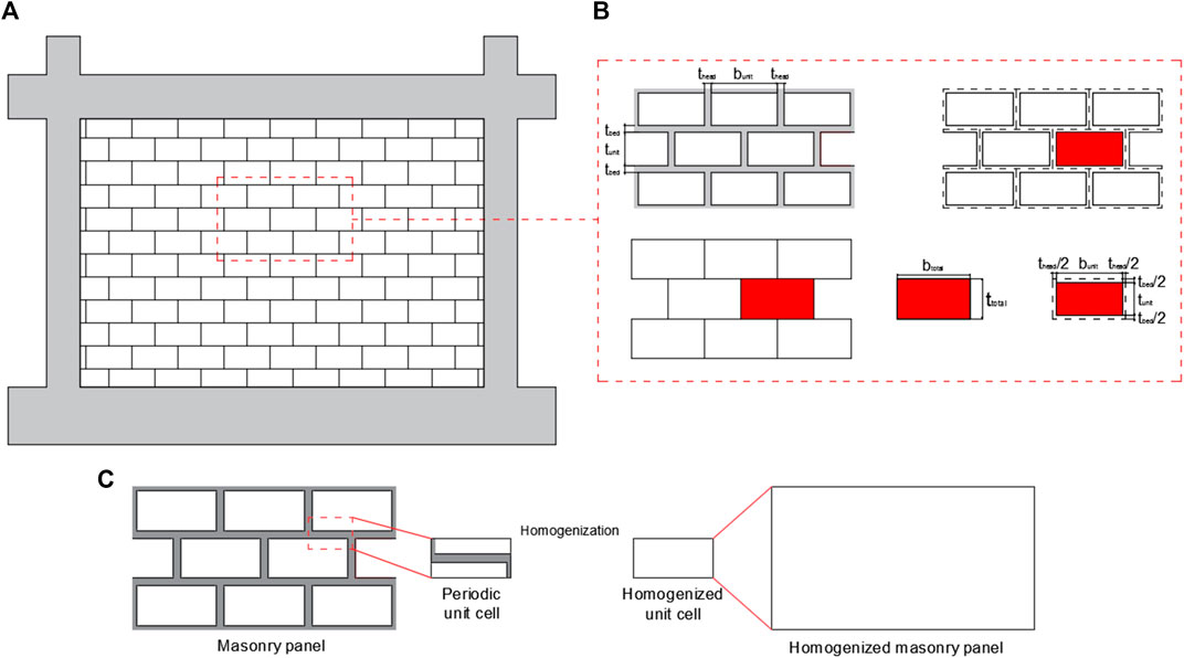
FIGURE 1. Micro and meso modeling approaches (A) infilled frame (B) transforming detailed to simplified micro modeling according to Lourenço Paulo and Rots. (1997) (C) homogenization procedure.
2.2 Meso-Modeling
In meso-modeling, the masonry infills are considered homogenized elements. This method required the definition of equivalent material properties that can produce the same behavior as the masonry infill. To this aim, Lopez et al. (1999), Anthoine (1995), Sacco (2009), Quinteros et al. (2012), and Houda et al. (2017) used the concept of the periodic unit cell to homogenize the masonry walls, also known as the representative element of volume (REV) such as in Ma et al. (2001) and Tiberti and Milani (2020a). This procedure is based on selecting a small element from the masonry wall that contains all the components and can generate the all-masonry wall with repetition of this element. The previous concept required regular distribution of the brick units and mortar joints. On the other hand, when the masonry panel is not periodically arranged, Tiberti and Milani (2020b) used the concept of test-window to employ the homogenized procedure. Figure 1C illustrates the homogenization procedure for a periodic masonry panel.
2.3 Macro-Modeling
The previous method is a complex task. The long computational time needed to solve the models made it inappropriate in engineering practice. Otherwise, the macro-modeling approach simplifies the contribution of the masonry infill on the global behavior based on its physical acting when the surrounded frame is subjected to lateral loads (Figure 2A). The masonry infills are treated as single or multiple diagonal struts. Besides, it represents a more practical tool in engineering practice. The main geometric property required is the width of the strut.
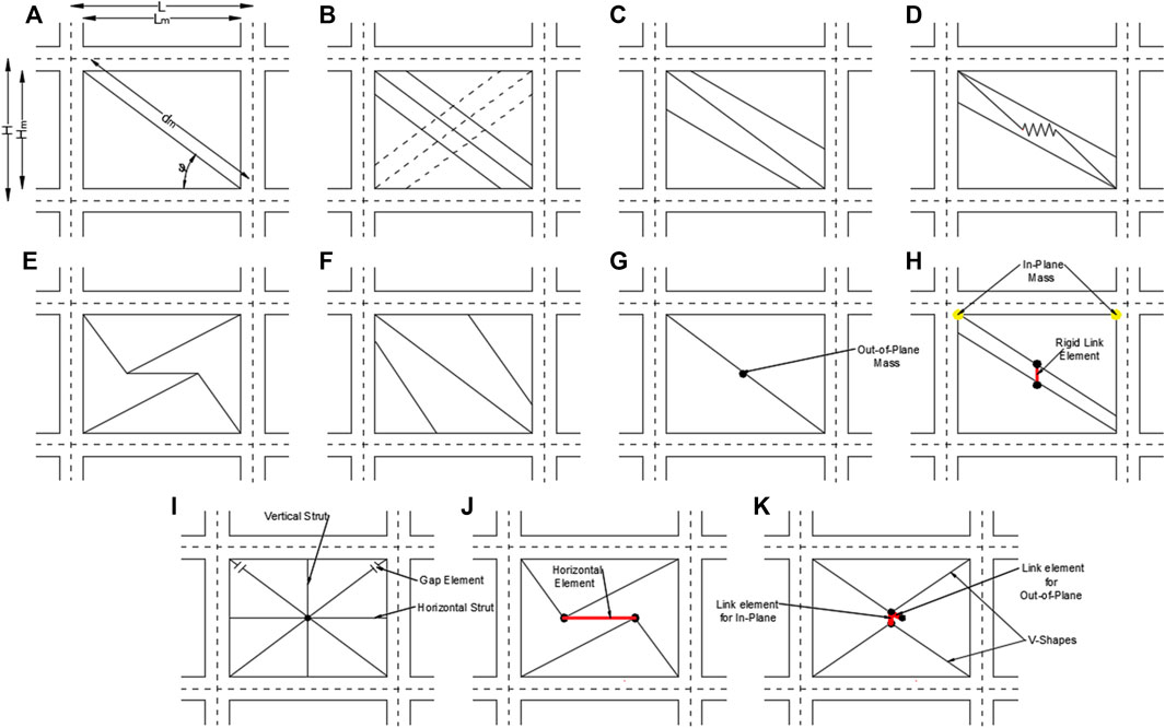
FIGURE 2. Macro models: (A) one diagonal strut model (B) multi-strut model of Chrysostomou (1991) (C) El-Dakhakhni and Hamid (2003) (D) Crisafulli and Carr (2007) (E) Rodrigues and Costa (2010) (F) Yekrangnia and Mohammadi (2017) Developed macro model to consider in-plane and out-of-plane interactions: (G) Kadysiewski and Mosalam (2009) (H) Donà et al. (2017) (I) Trapani et al. (2018) (J) Furtado et al. (2016) (K) Gesualdi et al. (2020).
Several equations proposed to calculate the width of the diagonal strut are reported in this section. The selected equations relate the width of the strut to the diagonal length and inclination, the thickness, and the mechanical properties of the masonry and concrete materials. In addition, the dimensions and the type of brick units can affect the width of the strut, where larger brick units will affect the total arrangement of the masonry infill, which implies an effect on the diagonal behavior of the masonry wall. The first expression suggested is that proposed by Holmes (1961), known as the one-third rule. The width of the strut Eq. (1) is considered to be one-third the diagonal length of the masonry infill.
According to Mainstone R. J. (1974), the width of the strut (Eq. 2) is related to masonry unit types (Bricks units or concrete blocks). This equation is adopted by the Federal Emergency Management Agency [FEMA (2000)]. The proposed expression is related to a dimensionless parameter
where
Liauw and Kwan (1984) relate the width to the angle of the diagonal strut, as indicated in Eq. (5). This equation is applied when the diagonal strut inclination ranges between 25° and 50° Nicola et al. (2015). Decanini and Fantin (1986) suggestion (Eq. 6) takes into account the status of the masonry infill wall and cracked or uncracked masonry infills (as reported in Hossameldeen Mohamed Ahmed, (2017)). Moghaddam and Dowling (1988)’s expression (Eq. 7) is independent of the relative stiffness. More recently, Turgay et al. (2014) proposed an expression (Eq. 8) that is dependent on the height–length ratio of masonry. The equation is applicable when the ratio is between 1.2 and 2.
As mentioned by Asteris Panagiotis G. et al. (2011), the shortcoming of the single strut models is the incapability to capture the internal effects of masonry (frame-infill interaction, bending moments, and shear forces in the frame elements.). More complex models are proposed to represent the masonry infills with multi-struts. According to El-Dakhakhni et al. (2003), the complexity and the accuracy of macro-models are dependent on the number of struts. As an example, a three-strut model is more complicated and accurate than the single and two-strut models. Chrysostomou (1991) suggested a six-strut model (Figure 2B), three struts in each direction. The model contains one diagonal strut and two off-diagonal struts positioned at the critical points of frame members. Figure 2C illustrates the multi-strut model proposed by El-Dakhakhni et al. (2003) to include the effects of masonry infills on the stiffness and strength of the infilled steel frames. Another multiple strut model is proposed by Crisafulli and Carr (2007). The masonry infills are represented with two diagonal struts connected by a shear spring, as shown in Figure 2D. The objective of the shear spring is to represent the shear behavior of the masonry wall. The model by Rodrigues et al. (2010) is formed by four struts related to each other with a horizontal central element (Figure 2E).
Based on a numerical study using ABAQUS Yekrangnia and Mohammadi (2017), proposed a multi-strut model. At a lower drift level, the authors observed the formation of a single diagonal strut. At high drifts, the single strut developed into two diagonal struts. Based on these observations, Yekrangnia and Mohammadi (2017) proposed a three-strut model. The model is composed of one diagonal and two off-diagonal struts, as shown in Figure 2F. Equation (9) is proposed to calculate the width of the off-diagonal struts. This equation is related to the model proposed by Mainstone R. J. (1974). For the diagonal strut, the width is considered to be one-half the off-diagonal width. Equation (12) defines the positions of the off-diagonal struts.
where
Other researchers improved the macro-modeling technique to account for both the in-plane and the out-of-plane behaviors. Kadysiewski and Mosalam (2009) developed a practical model to include the effect of the in-plane and the out-of-plane behaviors of the masonry infill. The proposed model is based on representing the masonry infill with a single diagonal strut, which is sufficient to represent both behaviors of the masonry infill, works in tension and compression, and has a lumped mass at the mid of the diagonal length that works in the out-of-plane direction. Figure 2G illustrates the model proposed by Kadysiewski and Mosalam (2009). Mosalam and Günay (2015) developed a single strut macro-model that can account for the in-plane and out-of-plane interaction. Furthermore, Longo et al. (2018) used the principle of the single diagonal strut to model the in-plane and out-of-plane behaviors. Longo et al. (2018) adopted the model proposed by Mosalam and Günay (2015). In addition to that, the authors assigned elastic springs at the column-beam joints in order to reproduce a realistic out-of-plane stiffness. Donà et al. (2017) proposed a two-strut model to combine both behaviors (Figure 2H). The model is developed based on the model proposed by Mosalam and Günay (2015). This model contains two diagonal struts modeled as the same way as Crisafulli and Carr (2007)’s model. Donà et al. (2017) assigned two types of weights. The first type works in the in-plane direction, located at each beam-column joint. The second type works in the out-of-plane direction located at the mid-length of each strut and connected with a rigid link element. Trapani and Cavaleri, (2018) developed a macro-model that is applicable in static and dynamic analyses. The proposed model contains four struts, a vertical and a horizontal strut, and two diagonal struts, one in each direction. Each strut represents two beam-column elements with fiber cross sections. The authors report that the model can capture the arching action of the out-of-plane deformation and the interaction of the in-plane and out-of-plane behaviors. Figure 2I illustrates the model proposed by Trapani and Cavaleri, (2018). Furtado et al. (2016) developed the multi-strut model proposed by Rodrigues et al. (2010) to account for the in-plane and out-of-plane interaction. Using OpenSees software, Furtado et al. (2016) connected the diagonal strut with a nonlinear link element. The out-of-plane masses are assigned to the two extremity nodes of the horizontal element, as illustrated in Figure 2J. After, Al Hanoun and Schwarz, (2019) implemented the model to a practical graphical user interface software (SAP 2000).
Moreover, Mazza (2021) and Mazza and Donnici (2021) modeled the in-plane and the out-of-plane behaviors and their interaction with the same multi-strut model. In the studies, the in-plane behavior is described with the horizontal truss, and the out-of-plane response is represented with four diagonal elements (Figure 2J). The lateral stiffness of the in-plane behavior is defined by Mainstone R. J. (1974)’s model, while the out-of-plane initial stiffness was defined by deriving the lumped masses and the vibration frequency of the masonry infill. Gesualdi et al. (2020) studied the seismic performance of residential RC buildings by considering the two behaviors. The masonry infill is modeled with four diagonal struts forming two V-shapes. The V-shapes are connected with nonlinear zero-length link elements to reproduce the in-plane degradation due to the cyclic load. The same link element type is used to model the out-of-plane degradation. A lumped mass represents the out-of-plane mass that is assigned to the node that connects V-shapes. Figure 2K illustrates the model with V-shapes.
Figure 3 illustrates the variation of the strut width models according to the relative stiffness. The strut width models could be classified according to the relative stiffness as dependent and independent equations. For the equations related to the relative stiffness [Mainstone RJ. (1974), Liauw and Kwan (1984), Decanini and Fantin (1986); Turgay et al. (2014)], the increase of the relative stiffness leads to decrease in the w/d ratio which applies a decrease in the width of the strut. After the relative stiffness exceeds a value of six, the variation is almost considered constant. On the other hand, the independent expressions indicate constant values during the variation of the relative stiffness. A high strut width value is presented by the equation proposed by Holmes (1961) when the relative stiffness exceeds a value of 3, which is the case in the considered experimental value (4.7). However, the expressions proposed by Mainstone R. J. (1974) and Yekrangnia and Mohammadi (2017) indicate the lowest strut widths during the variation of the relative stiffness.
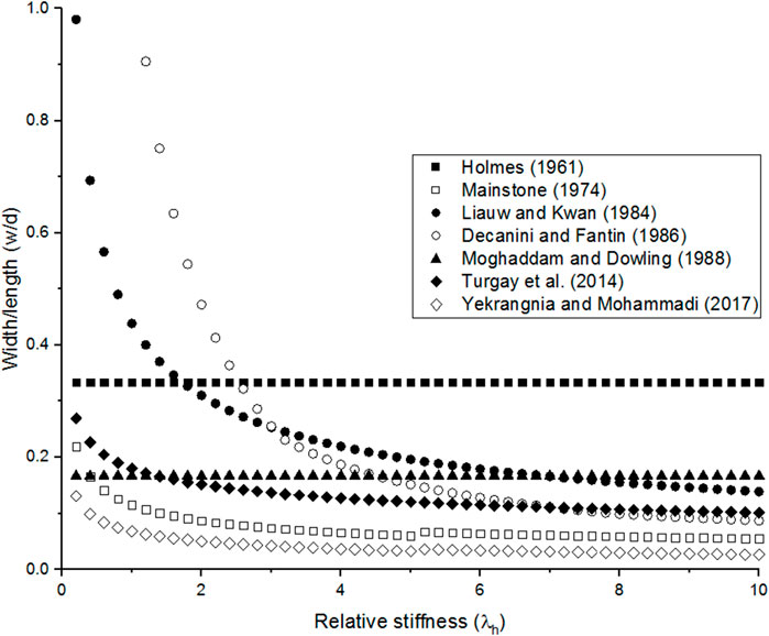
FIGURE 3. Comparison between difference strut width equations according to the variation of the relative stiffness for the frame of Specimen 9 (Mehrabi et al., 1996).
3 Description of the Experimental Study
Twelve experimental tests on one-story, one-bay, 1/2 scale R/C frames infilled with concrete masonry units are tested by Mehrabi et al. (1996) to investigate the effect of four different parameters: the masonry unit type, aspect ratio, lateral load type, and distribution of vertical force on the behavior of the infilled frames. Two infilled frames with the same geometric characteristics, namely, specimens 8 and 9 are selected from the experimental test to calibrate the numerical simulation. The specimens have an aspect ratio of 0.67 and are subjected to in-plane monotonic lateral loads and vertical loads distributed on beams and columns. The frames are designed according to Institute American Concrete (1989) to resist lateral wind loads. The masonry infills are constructed with (92 × 92 × 194) mm3 hollow and solid units in specimens 8 and 9, respectively. A type S mortar is used to connect the brick units. The joint’s thickness is 10 mm. According to Mehrabi et al. (1996), the compression stress of the solid units is higher than that of hollow units by 1.5 times. For the concrete, the compressive strength and the elastic modulus are 26.8 and 17225 MPa, respectively. For masonry infills, the compression strengths are 9.5 and 14.2 MPa and the elastic modulus are 5089.6 and 8233.6 MPa for specimens 8 and 9, respectively. The geometry of the infilled frame and the details of the frame elements are illustrated in Figures 4A–C.
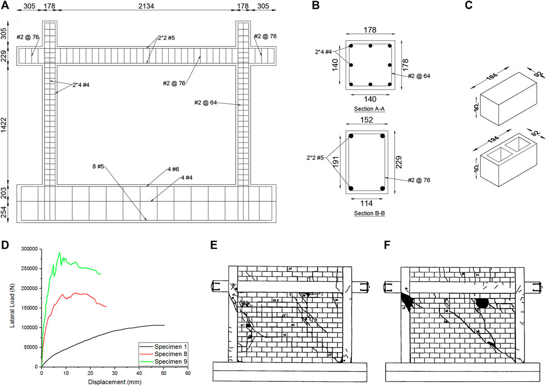
FIGURE 4. Details and results of specimens 8 and 9 (units in N and mm): (A) R/C frame (B) column and beam cross-sections (units in mm) (C) brick units geometry (D) Force displacement curve (E) and (F) failure modes at the end of experimental tests (Mehrabi et al., (1996)).
Figure 4D illustrates the force–displacement curves obtained from the experimental test for specimens 8 and 9. Figure 4E, F illustrates the failure modes at the end of each test, where the solid line and areas represent the cracks and the crushes, respectively. Before reaching the maximum loads, minor diagonal and sliding cracks start to develop along with the infill panel. In the case of specimen 8, the former failure modes were followed by sliding in the bed joints, and at high displacement amplitudes, crushing failure at the masonry panel occurred (Figure 4E). In the case of specimen 9, the diagonal cracks were followed by shear cracks that appeared in the columns. These cracks are extended until the end of the test (Figure 4F).
4 Finite Element Modeling
4.1 Reinforced Concrete Frame Modeling
4.1.1 Concrete
The concrete material is modeled using the SOLID65 element available in the ANSYS library. This element has cracking and crushing capabilities in case of tension or compression, respectively [ANSYS Mechanical APDL Element Reference (2013)].
The failure surface used in ANSYS for brittle materials is that proposed by Willam (1975). At least four parameters are required to define the model: the shear transferring coefficients for open and closed cracks and compression and tension stresses. The limitation of Willam (1975)’s model is the linear behavior, where the material behaves linearly until it is cracked or crushed [ANSYS (2013)]. In order to overcome this issue, the compressive stress is deactivated and replaced by non-linear stress–strain relationships [Mohyeddin et al. (2013)]. The nonlinear relationships (Figure 5A) are obtained using the confined concrete model proposed by Scott et al. (1982), known as the modified Kent and Park (1971) model. In tension, the material is considered to behave linearly. The tension stress is assumed to be 10% the compressive stress [Mohyeddin-Kermani, (2011)]. The mechanical properties adopted for concrete are 26.8 and 17225 MPa for compressive and elastic modulus, respectively.
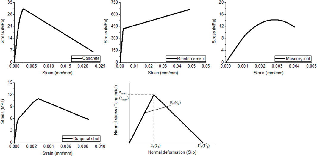
FIGURE 5. Adopted nonlinear Stress-strain relationships for: (A) confined concrete (Modified Kent and Park, 1971) (B) longitudinal reinforcements (C) masonry infill (micro-model) (D) diagonal strut (macro-model) (E) cohesive zone material (CZM) for contact pairs (ANSYS, 2013).
4.1.2 Reinforcement
The reinforcements are modeled with a LINK180. This element is used to model trusses, cables, springs, and links. It has the capability to represent the tension and/or compression elements with no bending resistance [ANSYS Mechanical APDL Element Reference (2013)]. The nonlinear behavior of this element is defined by the bilinear behavior (Figure 5B). The second slope (
4.2 Masonry Infills
4.2.1 Micro-Model
The masonry infills are modeled using the simplified micro modeling approach where the mortar thickness is halved and assigned to the adjacent unit. The element and procedure used to model the concrete material are used to model the masonry material. The tensile stress of masonry is considered to be 10% the compressive strength [Mohyeddin-Kermani, (2011)]. The nonlinear stress–strain relationships (Figure 5C) implemented in ANSYS for masonry material are calculated from Hendry (1990)’s model (Eq. (13)). The strains at the peak stress are considered the same as those obtained from Mehrabi et al. (1996). The values are 0.0027 and 0.0026 for specimens 8 and 9, respectively.
where,
4.2.2 Contact Elements
The frame-infill interactions and that between masonry units are modeled with contact elements. Surface-to-surface contact elements CONTA174 combined with a target element TARGE170 are used. The contact elements are used to represent the contact and sliding between two element surfaces. The elements are defined with six or eight nodes depending on the shape of the contact surface. These elements support isotropic and orthotropic Coulomb friction, shear stress friction. In ANSYS, the cohesive zone material model (CZM) is combined with contact pairs to define the separation between two elements. The CZM model (Figure 5E) is identified by bilinear stress-separation relationships proposed by Alfano and Crisfield (2001). The contact tensile and shear behaviors are illustrated in Figure 5E.
4.2.3 Macro- and Meso-Models
In the macro-modeling approach, the masonry infills are modeled with the LINK180 element from ANSYS library. This element is a 3D spar that can be used in a variety of engineering applications (ANSYS Mechanical APDL Element Reference (2013)). Figure 6A illustrates the macro-modeling of masonry infills. To adapt this element as a diagonal strut, the compression-only option is activated by turning the third key option (KEYOPT (3)) to 2 (ANSYS Mechanical APDL Element Reference (2013)). The nonlinearity in this model is distributed along the length of the element.
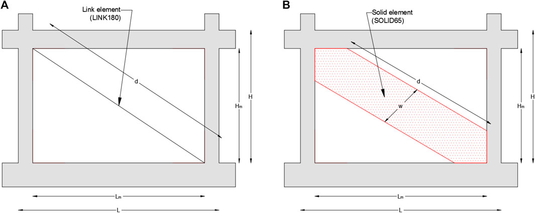
FIGURE 6. Modeling techniques of masonry infill: (A) Macro modeling (B) Meso modeling.
In meso-modeling, the masonry infills are modeled as a single homogenized diagonal element using the SOLID65 element. The diagonal element is modeled in the same direction of the stresses and strain distributions obtained. Figure 6B illustrates the meso-modeling of the masonry infills. The width is calculated according to Eqs. 1–8. The frame-homogenized element contacts are modeled with bonded contacts. The procedure used to model the concrete material is implemented to model the diagonal element.
The mechanical properties of the diagonal elements are defined from the behavior of the masonry infill. The masonry infill response is subtracted from the behavior of the infilled frame based on the hypotheses that consider the behavior of the infilled frame as a combination of its two components frame and infill [Mohamed and Xavier (2018)]. This method is used by many researchers such as Asteris et al. (2016), Liberatore et al. (2018), De Risi et al. (2018), and Mohamed and Xavier (2018). The infill force–displacement curves are projected to the diagonal direction to define the stress–strain relationships. The nonlinear behavior (Figure 5D) is obtained by dividing the forces and displacements by the diagonal length and the cross section of the diagonal strut. The elastic modulus is defined at 45% of the maximum stress. In this study, the tensile strength is removed. For multi strut models, the models proposed by Chrysostomou et al. (2002) and Yekrangnia and Mohammadi (2017) are used in this investigation. The behavior of the masonry infills is distributed between the diagonal and off-diagonal struts according to the method used by Verderame et al. (2019). The forces, displacements, and stiffnesses for each strut are calculated according to the equations (Eqs. (14)–(20) proposed by Chrysostomou et al. (2002).
where
The total width and the contact length in Chrysostomou et al. (2002)’s model are calculated using Eq. (21) [Liberatore et al. (2018)] and Eq. (22) [Stafford Smith (1976)]. The axial stiffness is obtained from the subtracted response of the infill masonry at 45% of the maximum load. Meanwhile, Eq. (9) and (12) are used to determine the width and the contact length in Yekrangnia and Mohammadi (2017)’s model. The absorbed portion (
Table 1 summarizes the width strut values obtained for specimens 8 and 9. As can be observed, similar values are presented in both specimens by using the models of Holmes (1961) and Moghaddam and Dowling (1988) because the width models are only related to the geometric properties. Otherwise, the other models indicate diverse values. The values obtained from the expression of Yekrangnia and Mohammadi (2017) represent the width of an off-diagonal strut. The width of the diagonal strut represents 50% of the presented value.
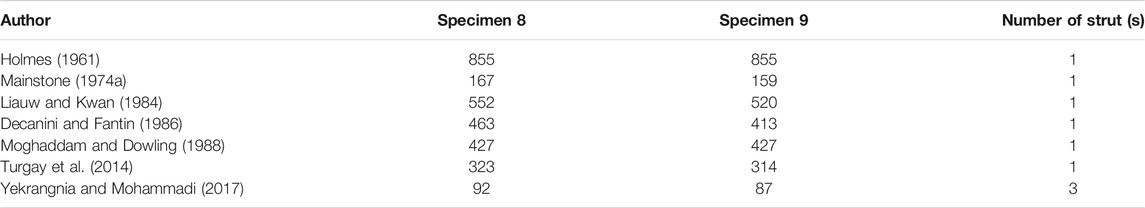
TABLE 1. Strut width values for specimen 8–9 (units in mm).
5 Results and Discussion
The results obtained from this analytical study are presented and discussed in this section. The dissection is split into two phases: 1) before reaching the maximum lateral load and 2) after reaching the maximum lateral load. Before the peak load, the results are compared in terms of maximum force (
5.1 Micro-Model Results
Figures 7A,B compare the experimental and FE force–displacement curves for specimens 8 and 9, respectively. It is clearly shown that the numerical model can predict the force and the stiffness of the infilled frames in both specimens. The deformation shapes of FE analyses are illustrated in Figure 7C, D for specimens 8 and 9, respectively. In numerical results, the cracks are presented as the separation between two different elements (units-frame elements or units-units). As indicated at the end of the experimental tests, different failure modes (shear sliding, diagonal cracking, minor compression crushing, damage within masonry wedge, and cracks in windward and leeward columns) are observed in specimen 8 (with weak infill). On the other hand, diagonal cracks, shear sliding of bed joints, crushing of masonry, and windward column are observed in specimen 9 (with strong infill). The numerical model presents only separations along bed joints which represent the shear sliding mode. Otherwise, the deformation shape obtained from specimen 9 presents diagonal and horizontal separations between masonry units which represent the diagonal cracking and the shear sliding compared to the experimental failure. The numerical models fail to represent the diagonal cracking in specimen 8 and crushing damages in both specimens.
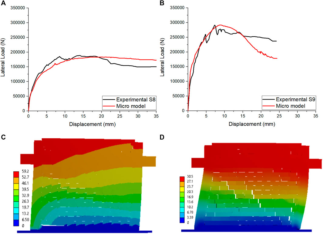
FIGURE 7. Results obtained from micro modeling: (A) (B) force-displacement curve comparison between experimental and numerical micro model specimens 8 and 9 (C) (D) deformation shapes of specimen 8 and 9 (units in N/mm).
The diagonal distributions of the stresses and the strains in the infilled frames, when the systems reach their peak strength, are illustrated in Figure 8. The diagonal distribution resulted in stress concentration in the top and bottom corners of windward and leeward columns, respectively. The figure also indicates that the distributions of the stresses and strains along the beam-infill contact are longer than the column-infill contact length; this is due to the vertical loads applied on the beam.

FIGURE 8. Distribution of stresses and strains: (A) (B) specimen 8 (C) (D) specimen 9.
5.2 Macro- and Meso-Models
5.2.1 Before the Maximum Load
Tables 2–4 summarize the analytical results before the curves reach maximum lateral force in each model. The micro-model results are presented in the first row. Since the force–displacement curves obtained from modeling the diagonal strut with an axial element are the same, the results are summarized in the second row. Otherwise, the other rows outline results obtained from meso-modeling.

TABLE 2. The results obtained from modeling specimen 8.
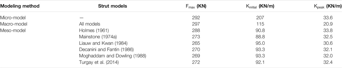
TABLE 3. The results obtained from modeling specimen 9.
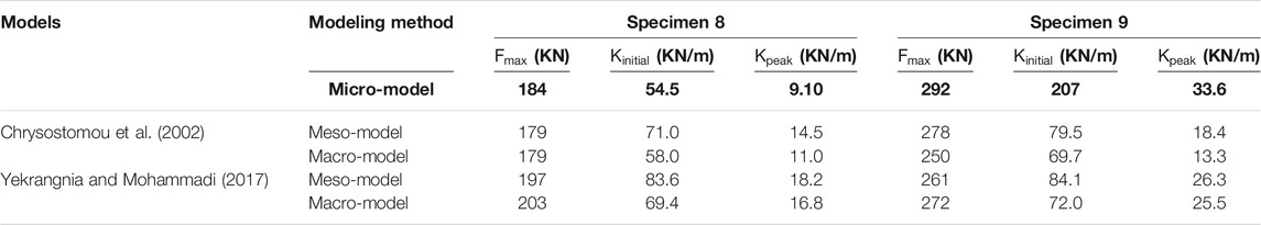
TABLE 4. The results of the multi-strut model.
5.2.1.1 Specimen 8
As indicated in Table 2, the micro-model gives good approximation in terms of force. The micro-model underestimates the experimental lateral force (184 KN) of the infilled frame by 2.8%. In terms of initial stiffness, the calculated stiffness is 54.5 KN/mm which represents 0.8 the experimental value. The experimental stiffness at peak force is 1.5 times higher than that obtained from the micro-model. By modeling the masonry infill with the macro-model, the maximum force (183 KN) is reached at a displacement of 6.77 mm. This model gives stiffness, at peak force, the value that is 2 times higher than that of the experimental. In the case of the initial stiffness, the numerical model shows a value 1.5 times higher than that of the experimental.
The results obtained from meso-modeling indicate that the width models of Holmes (1961) and Liauw and Kwan (1984) show higher errors than the other models; the models underestimate the lateral force by 15.3 and 10%, respectively. In terms of initial stiffness, the models show differences of 17.6 and 12.8%, respectively. The numerical stiffness at the peak load is 1.1 higher than the experimental values for both models. Using the model proposed by Mainstone R. J. (1974), the maximum lateral force is more approximate to the experimental value. The lateral force is 177 KN which is 6.2% lower than that of the experimental value. While the initial stiffnesses and the stiffness at the peak force are 1.1 and 1.4 times higher.
The maximum forces record from Decanini and Fantin (1986)’s, and Moghaddam and Dowling (1988)’s models are lower by around 8% than that in the experimental test. The difference is reduced to 7% in case of using the model of Turgay et al. (2014). The initial stiffness is overestimated by around 13% in the models of Decanini and Fantin (1986) and Moghaddam and Dowling (1988) and Turgay et al. (2014), while the stiffness at the peak force is 1.13 times the experimental value.
5.2.1.2 Specimen 9
The width models used to model specimen 8 are used for specimen 9. The results obtained from the numerical analyses are summarized in Table 3. As presented, the micro model results overestimate the lateral force by 0.12%. The maximum force that reached at a displacement 8.68 mm implies a difference of 16% in the stiffness at the peak load compared to the experimental value. However, the numerical initial stiffness is 2.3 times higher.
Using macro-models, the numerical force is 297 KN, which reached at a displacement of 14.2 mm. The stiffness obtained at the peak force is around 2 times lower than the experimental value. In terms of initial stiffness, the numerical value is 28% lower. Using meso-modeling, the width models proposed by Holmes (1961) show the approximate lateral force (1%) compared to the other width models. The initial stiffness is overestimated by 1.6%. Meanwhile, the stiffness at the peak load is underestimated by 16%. In terms of lateral force, the models of Mainstone RJ. (1974) and Turgay et al. (2014) show a difference of 6%. This difference is decreased to around 7.5% by using Decanini and Fantin (1986)’s and Moghaddam and Dowling (1988)’s models. The higher difference is obtained from using Liauw and Kwan (1984)’s model (9%).
In terms of initial stiffness, the model of Mainstone R. J. (1974) gives the approximate value where a difference of 0.5% is obtained. The models of Decanini and Fantin (1986) and Moghaddam and Dowling (1988) overestimate the initial stiffness by 4.5%. A higher value is obtained by Liauw and Kwan (1984). The model of Turgay et al. (2014) shows a value of 92.1 KN/m. In terms of stiffness at the peak load, the models of Holmes (1961), Mainstone RJ. (1974, Liauw and Kwan (1984), Decanini and Fantin (1986), Moghaddam and Dowling (1988), and Turgay et al. (2014) are 15.5, 19, 23.5, 20, 20, and 19%, respectively.
The results obtained from modeling the masonry infills with three-strut models are presented in Table 4. In terms of maximum lateral force, the values obtained from macro-modeling [Chrysostomou et al. (2002)’s model] are 179 KN and 250 KN for specimen 8 and 9, respectively. The values underestimated the experimental force by 5 and 14%, respectively. Using Yekrangnia and Mohammadi (2017)’s model, the lateral strength is overestimated by 7% in specimen 8 and underestimated in specimen 9 by 6%. In meso-modeling, the errors are around 5% using Chrysostomou et al. (2002)’s model. Meanwhile, in Yekrangnia and Mohammadi (2017)’s model, the differences between experimental end numerical results are 4 and 10% for specimen 8 and 9, respectively.
In terms of stiffness, both models overestimate the initial stiffness and stiffness at the peak load of the specimen 8 with difference varying between 0.5 and 35%; only in macro-modeling of Chrysostomou et al. (2002)’s model, the stiffnesses are underestimated by 19 and 16%, respectively. In specimen 9, the numerical stiffnesses underestimated experimental values with difference varying between 8 and 67%.
5.2.2 Post-peak Behavior
Figures 9–11 illustrate the force–displacement curves obtained from numerical analyses. In Figure 11, the results obtained from Chrysostomou et al. (2002) are presented in green color, and the blue color represents the results of using Yekrangnia and Mohammadi (2017). In general, the lateral force decreases when the peak force is reached for all numerical models. In the micro-model, the numerical model of specimen 8 presents a slight decrease compared to the experimental curve where the numerical curve records a reduction of 6% while the experimental decreasing is around 20% at the end of the test. However, the numerical results of specimen 9 show a significant decrease in the lateral force. The numerical force is dropped to 39% of the maximum load whereas the experimental results show a reduction of 19%.
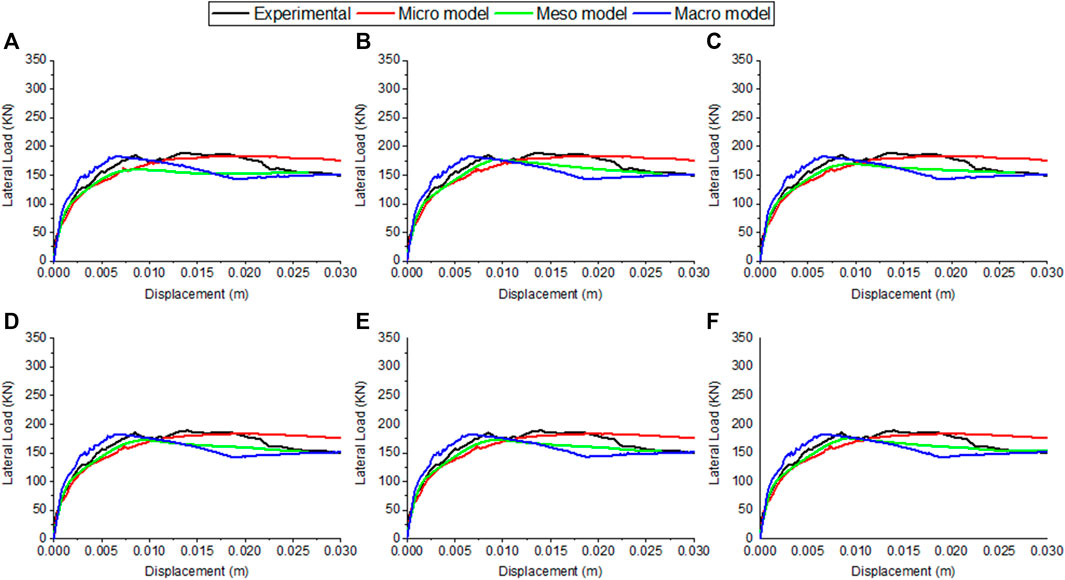
FIGURE 9. Comparison between experimental and numerical macro models for specimen 8: (A) Holmes (1961) (B) Mainstone (1974) (C) Liauw and Kwan (1984) (D) Decanini and Fantin (1986) (E) Moghaddam and Dowling (1988) (F) Turgay et al. (2014).
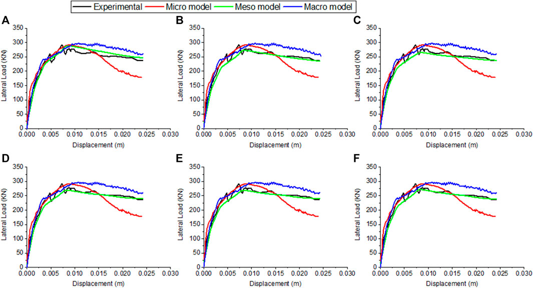
FIGURE 10. Comparison between experimental and numerical macro models for specimen 9: (A) Holmes (1961) (B) Mainstone (1974) (C) Liauw and Kwan (1984) (D) Decanini and Fantin (1986) (E) Moghaddam and Dowling (1988) (F) Turgay et al. (2014).
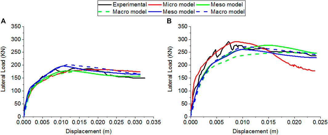
FIGURE 11. Comparison between experimental and multi-strut models: (A) Specimen 8 (B) Specimen 9.
In macro- and meso-models, the curves obtained from analyzing specimen 8 (Figure 9) show approximate behavior after the lateral load reaches its maximum value compared to the experimental and micro-model results. The same note can be observed in specimen 9 (Figure 10). The lateral forces at the end of analyses are approximately the same as the experimental values, 150 KN in specimen 8 and 237 KN in specimen 9. The lateral forces are reduced by 19% in both specimens.
6 Conclusion
This work contains a numerical investigation on the accuracy of width strut models using meso-modeling. The homogenized concept is used to model the masonry infill as a diagonal element. In addition, the work contains a comparison between micro-, meso-, and macro-modeling techniques of infills surrounded by reinforced concrete frames using the finite element software ANSYS. Two experimental specimens with weak and strong infill panels subjected to monotonic increasing lateral loading are selected to calibrate the numerical study.
First, seven width models are selected. The variation of the strut width equation according to the relative stiffness indicates that the selected equations can be classified according to the relative stiffness to dependent and independent equations. The dependent equations show constant width values during the variation of the relative stiffness. Otherwise, the independent equations show a reduction of width values during the increase of the relative stiffness.
Next, the masonry is modeled using a simplified micro-model. The global responses of the infilled frames of the experimental test are well predicted using the simplified micro-modeling approach (in terms of strength and stiffness). The deformation shapes of the numerical models can capture the shear sliding in specimen 8. While in specimen 9, the numerical model can capture the diagonal and sliding cracks. In macro-modeling, the masonry infills are modeled using a 3D spar, known as LINK180. In meso-modeling, the masonry infills are modeled as an equivalent homogenized diagonal element using SOLID65. The width is calculated according to the models used in macro-models.
In general, the macro-modeling with a single-strut model indicates the capability of the single strut to capture the global behavior of the infill frames. The force-deformation curves obtained from different macro-modeling show the same curve. Using meso-modeling, the single-strut models are more predictable to the global response by using Mainstone R. J. (1974) and Turgay et al. (2014)’s models in specimens 8 and 9. The model of Holmes (1961) gives the approximate behavior in specimen 9 compared to other models. Moreover, the models of Liauw and Kwan (1984), Decanini and Fantin (1986), and Moghaddam and Dowling (1988) show acceptable results. In the case of the multi-strut model, the models of Chrysostomou et al. (2002) and Yekrangnia and Mohammadi (2017) show approximate behavior using meso- and macro-modeling techniques. The models underestimate the lateral behavior of infill masonry in both modeling techniques, except for the model of Yekrangnia and Mohammadi (2017) where the behavior is overestimated in specimen 8 using meso- and macro-modeling. Finally, the modeling of the diagonal strut (s) with the meso-modeling technique presents an acceptable tool to study the diagonal behaving infill masonry. Further works are needed to investigate the application of the meso-modeling technique on infilled frames subjected to cyclic loading.
Data Availability Statement
The original contributions presented in the study are included in the article/Supplementary Material, further inquiries can be directed to the corresponding author.
Author Contributions
MB was responsible for writing, methodology, software, and validation. ZB carried out the methodology, writing, and supervision.
Conflict of Interest
The authors declare that the research was conducted in the absence of any commercial or financial relationships that could be construed as a potential conflict of interest.
Publisher’s Note
All claims expressed in this article are solely those of the authors and do not necessarily represent those of their affiliated organizations, or those of the publisher, the editors, and the reviewers. Any product that may be evaluated in this article, or claim that may be made by its manufacturer, is not guaranteed or endorsed by the publisher.
References
Al Hanoun, M. H., Abrahamczyk, L., and Schwarz, J. (2019). Macromodeling of in- and Out-Of-Plane Behavior of Unreinforced Masonry Infill walls. Bull. Earthquake Eng. 17 (1), 519–535. doi:10.1007/s10518-018-0458-x
Al-Chaar, Ghassan., Mehrabi, A. B., and Manzouri, Teymour. (2008). Finite Element Interface Modeling and Experimental Verification of Masonry-Infilled R/C Frames. Longmont, CO: Masonry Society.
Alfano, G., and Crisfield, M. A. (2001). Finite Element Interface Models for the Delamination Analysis of Laminated Composites: Mechanical and Computational Issues. Int. J. Numer. Meth. Engng. 50 (7), 1701–1736. doi:10.1002/nme.93
ANSYS Mechanical APDL Element Reference (2013). ANSYS Mechanical APDL Theory Reference. Canonsburg, WA: ANSYS Inc Release15, 1–909. Availabe at: www.ansys.com.
Anthoine, A. (1995). Derivation of the In-Plane Elastic Characteristics of Masonry through Homogenization Theory. Int. J. Sol. Structures 32 (2), 137–163. doi:10.1016/0020-7683(94)00140-r
Asteris, Panagiotis. G., Kakaletsis, D. J., and Chrysostomou, Christis. (2011b). Failure Modes of In-Filled Frames. Electron. J. Struct. Eng.
Asteris, P. G., Antoniou, S. T., Sophianopoulos, D. S., and Chrysostomou, C. Z. (2011a). Mathematical Macromodeling of Infilled Frames: State of the Art. J. Struct. Eng. 137 (12), 1508–1517. doi:10.1061/(asce)st.1943-541x.0000384
Asteris, P. G., Cavaleri, L., Di Trapani, F., and Sarhosis, V. (2016). A Macro-Modelling Approach for the Analysis of Infilled Frame Structures Considering the Effects of Openings and Vertical Loads. Struct. Infrastructure Eng. 12 (5), 551–566. doi:10.1080/15732479.2015.1030761
Chrysostomou, Christis. Zenon. (1991). Effects of Degrading Infill Walls on the Nonlinear Seismic Response of Two-Dimensional Steel Frames. NY, USA: Cornell University Ithaca.
Chrysostomou, C. Z., Gergely, P., and Abel, J. F. (2002). A Six-Strut Model for Nonlinear Dynamic Analysis of Steel Infilled Frames. Int. J. Struct. Stab. Dyn. 2 (3), 335–353. doi:10.1142/s0219455402000567
Crisafulli, F. J., and Carr, A. J. (2007). Proposed Macro-Model for the Analysis of Infilled Frame Structures. Bnzsee 40 (2), 69–77. doi:10.5459/bnzsee.40.2.69-77
Crisafulli, F. J., Carr, A. J., and Park, R. (2000). Analytical Modelling of Infilled Frame Structures. Bnzsee 33 (1), 30–47. doi:10.5459/bnzsee.33.1.30-47
De Risi, Maria. Teresa., Del Gaudio, Carlo., Ricci, Paolo., and Mario Verderame, Gerardo. (2018). In-Plane Behaviour and Damage Assessment of Masonry Infills with Hollow Clay Bricks in RC Frames. Eng. Structures 168, 257–275. doi:10.1016/j.engstruct.2018.04.065
Decanini, L. D., and Fantin, G. E. (1986). Modelos Simplificados de La Mampostería Incluida En Porticos. Caracteristicas de Stiffnessy Resistencia Lateral En Estado Limite. Jornadas Argentinas de Ingeniería Estructural 2, 817–836.
Donà, Marco., Tecchio, Giovanni., Domenicale, Luca., Saler, Elisa., Minotto, Massimiliano., and da Porto, Francesca. (2017). “Directional Effects on Combined In-Plane and Out of Plane Seismic Behavior of Masonry Infills,” in Proceedings of the 6th International Conference on Computational Methods in Structural Dynamics and Earthquake Engineering (COMPDYN 2015). doi:10.7712/120117.5649.18570
El-Dakhakhni, W. W., Elgaaly, M., Hamid, A. A., and Hamid, Ahmad. A. (2003). Three-Strut Model for Concrete Masonry-Infilled Steel Frames. J. Struct. Eng. 129 (2), 177–185. doi:10.1061/(asce)0733-9445(2003)129:2(177)
Fema, B. S. S. (2000). Prestandard and Commentary for the Seismic Rehabilitation of Buildings. Washington, DC.
Furtado, A., Rodrigues, H., and Arêde, A. (2015). Modelling of Masonry Infill Walls Participation in the Seismic Behaviour of RC Buildings Using OpenSees. Int. J. Adv. Struct. Eng. 7 (2), 117–127. doi:10.1007/s40091-015-0086-5
Furtado, A., Rodrigues, H., Arêde, A., and Varum, H. (2016). Simplified Macro-Model for Infill Masonry walls Considering the Out-Of-Plane Behaviour. Earthquake Engng Struct. Dyn. 45 (4), 507–524. doi:10.1002/eqe.2663
Gesualdi, G., Viggiani, L. R. S., and Cardone, D. (2020). Seismic Performance of RC Frame Buildings Accounting for the Out-Of-Plane Behavior of Masonry Infills. Bull. Earthquake Eng. 18 (11), 5343–5381. doi:10.1007/s10518-020-00904-1
Hendry, A. W. (1990). “Masonry Materials and the Effect of Workmanship,” in Proceeding of 3rd International Seminar on Structural Masonry for Developing Countries (Scotland: University of Edinburgh).
Holmes, M. (1961). Steel Frames with Brickwork and Concrete Infilling. Proc. Inst. Civil Eng. 19 (4), 473–478. doi:10.1680/iicep.1961.11305
Hossameldeen Mohamed Ahmed, M. (2017). Seismic Risk Assessment of Reinforced Concrete Frames with Masonry Infill. Porto, Portugal: Universidade do Porto. (Portugal).
Houda, Friaa., Laroussi Myriam, Hellara., Ioannis, Stefanou., Karam, Sab., and Dogui, Abdelwaheb. (2017). “In-Plane Strength Domain Numerical Determination of Hollow Concrete Block Masonry,” in International Conference Design and Modeling of Mechanical Systems (Springer), 721–732. doi:10.1007/978-3-319-66697-6_70
Institute, American Concrete (1989). “Building Code Requirements for Reinforced Concrete (ACI 318-89)(Revised 1992) and Commentary-ACI 318R-89 (Revised 1992).” in. American Concrete Institute.
Kadysiewski, S., and Mosalam, K. M. (2009). Modeling of Unreinforced Masonry Infill Walls Considering In-Plane and Out-Of-Plane Interaction, PEER 2008/102. Berkeley: University of California.
Kakaletsis, D., and Karayannis, C. (2007). Experimental Investigation of Infilled R/C Frames with Eccentric Openings. Struct. Eng. Mech. 26 (3), 231–250. doi:10.12989/sem.2007.26.3.231
Kent, Dudley. Charles., and Park, Robert. (1971). Flexural Members with Confined Concrete. Reston, VA: Journal of the Structural Division.
Kong, J.-C., Zhai, C.-H., and Liu, C.-H. (2015). Two-Way Seismic Behaviour of Concrete Frames with Infill Walls. Proc. Inst. Civil Eng. - Structures Buildings 168 (9), 649–663. doi:10.1680/jstbu.14.00055
Liauw, T-C., and Kwan, K-H. (1984). Nonlinear Behaviour of Non-integral Infilled Frames. Comput. Structures 18 (3), 551–560. doi:10.1016/0045-7949(84)90070-1
Liberatore, L., Noto, F., Mollaioli, F., and Franchin, P. (2018). In-Plane Response of Masonry Infill Walls: Comprehensive Experimentally-Based Equivalent Strut Model for Deterministic and Probabilistic Analysis. Eng. Structures 167, 533–548. doi:10.1016/j.engstruct.2018.04.057
Longo, F., Wiebe, L., da Porto, F., and Modena, C. (2018). Application of an In-Plane/out-Of-Plane Interaction Model for URM Infill Walls to Dynamic Seismic Analysis of RC Frame Buildings. Bull. Earthquake Eng. 16 (12), 6163–6190. doi:10.1007/s10518-018-0439-0
Lopez, J., Oller, S., Oñate, E., and Lubliner, J. (1999). A Homogeneous Constitutive Model for Masonry. Int. J. Numer. Meth. Engng. 46 (10), 1651–1671. doi:10.1002/(sici)1097-0207(19991210)46:10<1651:aid-nme718>3.0.co;2-2
Lourenço Paulo, B., and Rots, Jan. G. (1997). Multisurface Interface Model for Analysis of Masonry Structures. J. Eng. Mech. 123 (7), 660–668. doi:10.1061/(asce)0733-9399(1997)123:7(660)
LouziRabab Abdel Karim, Al. (2015). Seismic In-Plane Response of Reinforced Concrete Frames with Masonry Infill Walls. West Lafayette, IN: Purdue University.
Ma, G., Hao, H., and Lu, Y. (2001). Homogenization of Masonry Using Numerical Simulations. J. Eng. Mech. 127 (5), 421–431. doi:10.1061/(asce)0733-9399(2001)127:5(421)
Mainstone, R. J., and Weeks, G. A. (1970). “27.-The Influence of a Bounding Frame on the Racking Stiffnesses and Strengths of Brick Walls,” in Proceedings of the 2nd International Brick Masonry Conference (Watford, England: Building Research Establishment), 165–171.
Mainstone, R. J. (1974a). On the Stiffness and Strength of In-Filled Frames. New York: Proc. Supplement, Trans. of Inst. Of Civil Eng. State Univ. of.
Mainstone, R. J. (1974b). Supplementary Note on the Stiffnesses and Strengths of Infilled Frames. Garston, United Kingdom: Building Research Establishment, Building Research Station.
Mazza, F. (2021). In-Plane and Out-Of-Plane Nonlinear Seismic Response of Masonry Infills for Hospitals Retrofitted with Hysteretic Damped Braces. Soil Dyn. Earthquake Eng. 148, 106803. doi:10.1016/j.soildyn.2021.106803
Mazza, F., and Donnici, A. (2021). In-plane and Out-Of-Plane Seismic Damage of Masonry Infills in Existing r.C. Structures: the Case Study of De Gasperi-Battaglia School in Norcia. Bull. Earthquake Eng. 19 (1), 345–376. doi:10.1007/s10518-020-00981-2
Mehrabi, A. B., Benson Shing, P., Schuller, M. P., and Noland, J. L. (1996). Experimental Evaluation of Masonry-Infilled RC Frames. J. Struct. Eng. 122 (3), 228–237. doi:10.1061/(asce)0733-9445(1996)122:3(228)
Mehrabi, A. B., and Shing, P. B. (1997). Finite Element Modeling of Masonry-Infilled RC Frames. J. Struct. Eng. 123 (5), 604–613. doi:10.1061/(asce)0733-9445(1997)123:5(604)
Moghaddam, H., and Dowling, P. J. (1988). Earthquake Resistant Design of Brick Infilled Frames. Brick and Block Masonry(8 Th IBMAC) London, 2. Elsevier Applied Science, 774–784.
Mohamed, Hossameldeen., and Xavier, R. O. M. Ã. O. (2018). Robust Calibration of Macro-Models for the In-Plane Behavior of Masonry Infilled RC Frames. J. Earthquake Eng., 1–27. doi:10.1080/13632469.2018.1517703
Mohyeddin, A., Goldsworthy, H. M., and Gad, E. F. (2013). FE Modelling of RC Frames with Masonry Infill Panels under In-Plane and Out-Of-Plane Loading. Eng. Structures 51, 73–87. doi:10.1016/j.engstruct.2013.01.012
Mohyeddin-Kermani, A. (2011). Modelling and Performance of RC Frames with Masonry Infill under In-Plane and Out-Of-Plane Loading.”
Mosalam, K. M., and Günay, S. (2015). Progressive Collapse Analysis of Reinforced Concrete Frames with Unreinforced Masonry Infill Walls Considering In-Plane/Out-Of-Plane Interaction. Earthquake Spectra 31 (2), 921–943. doi:10.1193/062113eqs165m
Nicola, T., Leandro, C., Guido, C., and Enrico, S. (2015). Masonry Infilled Frame Structures: State-Of-The-Art Review of Numerical Modelling. Earthquakes and Structures 8 (3), 733–759. doi:10.12989/eas.2015.8.3.733
Pantò, B., Caliò, I., and Lourenço, Paulo. B. (2018). A 3D Discrete Macro-Element for Modelling the Out-Of-Plane Behaviour of Infilled Frame Structures. Eng. Structures 175, 371–385. doi:10.1016/j.engstruct.2018.08.022
Petracca, M., Pelà, L., Rossi, R., Oller, S., Camata, G., and Spacone, E. (2017). Multiscale Computational First Order Homogenization of Thick Shells for the Analysis of Out-Of-Plane Loaded Masonry Walls. Comp. Methods Appl. Mech. Eng. 315, 273–301. doi:10.1016/j.cma.2016.10.046
Pires, Felicita., and Carvalho, E. Cansado. (1992). “The Behaviour of Infilled Reinforced Concrete Frames under Horizontal Cyclic Loading,” in Proceedings of the 10th World Conference on Earthquake Engineering, 6 3419–33422.
Polyakove, S. V. (1957). Masonry in Framed Buildings, an Investigation into the Strength and Stiffness of Masonry Infilled. Moscow. English translation.
Pradhan, B., and Cavaleri, L. (2020). IP-OOP Interaction in URM Infilled Frame Structures: A New Macro-Modelling Proposal. Eng. Structures 224, 111211. doi:10.1016/j.engstruct.2020.111211
Quinteros, R. D., Oller, S., and Nallim, L. G. (2012). Nonlinear Homogenization Techniques to Solve Masonry Structures Problems. Compos. Structures 94 (2), 724–730. doi:10.1016/j.compstruct.2011.09.006
Release, ANSYS Mechanical APDL (2013). 15, ANSYS Mechanical APDL Element Reference. Anleitung. Canonsburg USA: ANSYS Inc.
Riddington, J. R., and Naom, N. F. (1994). Finite Element Prediction of Masonry Compressive Strength. Comput. Structures 52 (1), 113–119. doi:10.1016/0045-7949(94)90261-5
Rodrigues, H., Varum, H., and Costa, A. (2010). Simplified Macro-Model for Infill Masonry Panels. J. Earthquake Eng. 14 (3), 390–416. doi:10.1080/13632460903086044
Sacco, E. (2009). A Nonlinear Homogenization Procedure for Periodic Masonry. Eur. J. Mech. - A/Solids 28 (2), 209–222. doi:10.1016/j.euromechsol.2008.06.005
Scott, Bryan. D., Park, Robert., and Priestley, Michael. J. N. (1982). Stress-Strain Behavior of Concrete Confined by Overlapping Hoops at Low and High Strain Rates.” in. J. Proc. 79, 13–27. doi:10.14359/10875
Smith, B. S. (1962). Lateral Stiffness of Infilled Frames. J. Struct. Div. 88 (6), 183–199. doi:10.1061/jsdeag.0000849
Smith, B. S. (1967). Methods for Predicting the Lateral Stiffness and Strength of Multi-Story Infilled Frames. Build. Sci. 2 (3), 247–257. doi:10.1016/0007-3628(67)90027-8
Tiberti, S., and Milani, G. (2020a). 3D Homogenized Limit Analysis of Non-periodic Multi-Leaf Masonry Walls. Comput. Structures 234, 106253. doi:10.1016/j.compstruc.2020.106253
Tiberti, S., and Milani, G. (2020b). 3D Voxel Homogenized Limit Analysis of Single-Leaf Non-periodic Masonry. Comput. Structures 229, 106186. doi:10.1016/j.compstruc.2019.106186
Trapani, F. Di., Shing, P. B., and Cavaleri, L. (2018). Macroelement Model for In-Plane and Out-Of-Plane Responses of Masonry Infills in Frame Structures. J. Struct. Eng. 144 (2), 4017198. doi:10.1061/(asce)st.1943-541x.0001926
Turgay, Tahsin., Cigdem Durmus, Meril., Binici, Baris., and Ozcebe, Guney. (2014). Evaluation of the Predictive Models for Stiffness, Strength, and Deformation Capacity of RC Frames with Masonry Infill Walls. J. Struct. Eng. 140 (10), 6014003. doi:10.1061/(asce)st.1943-541x.0001069
Verderame, G. M., Ricci, P., De Risi, M. T., and Del Gaudio, C. (2019). Experimental Assessment and Numerical Modelling of Conformin and Non-conforming RC Frames with and without Infills. J. Earthquake Eng.
Willam, Kaspar. J. (1975). Constitutive Model for the Triaxial Behaviour of Concrete. Proc. Intl. Assoc. Bridge Structl. Engrs 19, 1–30. doi:10.5169/seals-17526
Yekrangnia, M., and Mohammadi, M. (2017). A New Strut Model for Solid Masonry Infills in Steel Frames. Eng. Structures 135, 222–235. doi:10.1016/j.engstruct.2016.10.048
Keywords: finite element analysis, infilled frame, masonry, nonlinear analysis, reinforced concrete, micro model, meso model, macro model
Citation: Bouarroudj MA and Boudaoud Z (2022) Comparison Between Numerical Modeling Approaches of Infilled Frames Under In-Plane Load. Front. Built Environ. 7:783051. doi: 10.3389/fbuil.2021.783051
Received: 25 September 2021; Accepted: 15 December 2021;
Published: 25 February 2022.
Edited by:
Fabio Mazza, University of Calabria, ItalyReviewed by:
Gabriele Milani, Politecnico di Milano, ItalyAndré Furtado, University of Porto, Portugal
Maria Teresa De Risi, University of Naples Federico II, Italy
Copyright © 2022 Bouarroudj and Boudaoud. This is an open-access article distributed under the terms of the Creative Commons Attribution License (CC BY). The use, distribution or reproduction in other forums is permitted, provided the original author(s) and the copyright owner(s) are credited and that the original publication in this journal is cited, in accordance with accepted academic practice. No use, distribution or reproduction is permitted which does not comply with these terms.
*Correspondence: Mohammed Amin Bouarroudj, Ym91YXJyb3Vkam1vaGFtbWVkYW1pbkBnbWFpbC5jb20=