 Caspar L. D. Bain
 Gregory A. Kopp
  Ayman M. El Ansary
 - 1Boundary Layer Wind Tunnel Laboratory, Faculty of Engineering, University of Western Ontario, London, ON, Canada
- 2Department of Civil and Environmental Engineering, University of Western Ontario, London, ON, Canada
Light-frame wood construction comprises nearly 90% of the housing industry in Canada and the United States. The roofs of these houses can be constructed either entirely on site or using prefabricated trusses. Assembling the roof structure on site, otherwise known as stick-framing, is a framing technique with current code guidelines that are based on past practice and limited consideration of wind loads. This makes these roof structures susceptible to failure in high-speed wind events, such as tornadoes. This research proposes improved stick-framing guidelines that would work for EF-2 tornadoes. Using non-linear finite element analysis, a stick-framed roof was designed following the guidelines in the National Building Code of Canada. Non-linear links were used to model all of the connections between the members in the roof structure, with frame elements used to represent the members. Increasing wind loads were applied to the structure and the first elements of the roof that failed were improved using an iterative performance-based design approach until the performance target of resistance to EF-2 tornadoes was achieved. The failure of the roof-to-wall-connections and the lack of members used in the framing were the two main issues highlighted and addressed. Damage survey photos were used to compare failures observed in the model with failures after real tornado events, which demonstrate many similar failure modes. The research recommends the requirements to ensure stick-framed roofs can withstand EF-2 tornadoes. Most notable is an improved gable end frame, which gives the structure more roof-to-wall connections, as well as a more structurally sound frame where the loads are the highest. Other additions include struts, hurricane ties at all roof-to-wall connection locations and increased number of nails in various connections throughout the repeating inner frames. Minimum member sizes and qualities for each type of member used in the roof structure are also recommended.
1 Introduction
1.1 Background
Tornadoes cause significant damage to houses and other structures that lie in their paths. Additional to structural damage, there are many deaths and injuries associated with tornadoes as well. Recent examples include the Joplin, MO tornado in May of 2011, which resulted in over 50 deaths and more than 1,000 injuries, while causing losses of approximately 3 billion USD (Prevatt et al., 2012; Kuligowski et al., 2014). Another EF-5 tornado, the highest category on the Enhanced Fujita scale, touched down in Moore, OK in May of 2013. This tornado resulted in 24 deaths, over 200 injuries, and anywhere from 2 to 3.5 billion USD in damages (Atkins et al., 2014). In the United States in 2011 alone, tornadoes caused over 26 billion USD in insured losses (Smith and Matthews, 2015). There appear to be changing patterns associated with tornadoes and other high-wind events in North America in recent years (Emanuel, 2005; Elsner et al., 2019). With increased urbanization and changing patterns of high-wind events, losses are likely to increase without significant risk mitigation efforts (Bouwer, 2019), particularly for houses.
Houses in Canada and the United States are comprised mainly of light-frame wood construction. It is estimated approximately 90% of all residential buildings in the United States are constructed using this method (Ellingwood et al., 2004). For the roof structure, there are two primary methods in which light-frame wood construction can be implemented. Either prefabricated trusses, consisting of truss plates joining the members together, or stick-framing, where members are connected using various nail patterns on site, can be used to assemble the roof structure. Most houses in North America have either basic gable or hip roof shapes (Canadian Mortgage and Housing Corporation, 2014), or are composed of a combination of the two, making these two roof-assembly methods both common and practical. The benefits of using a technique such as stick-framing lie in its simplicity. Construction requires only the wood members and nails to complete a roof after the rest of the building is erected. However, guidelines utilized in stick-framing are based on very old test data and common practice in the field. Thus, guidance for high-wind events, such as tornadoes, is needed, if loss reduction is to be achieved.
Improving building codes for residential wood-frame buildings to account for EF-2 tornadoes is possible using fairly conventional construction methods, but for tornadoes categorized as EF-3 or higher, other construction methods would have to be implemented, making it much less practical (Amini and van de Lindt, 2014). After the tornado in Moore, OK, the city implemented enhanced building codes for tornadoes ranging from EF-0 to EF-2. Even though EF-5 tornadoes are much more destructive, about 90% of all tornadoes in the United States are EF-2 or lower (Storm Prediction Center, 2014) making them far more common, leading to about 46% of all losses (Simmons et al., 2015). If the new standards implemented in the city of Moore were applied to all of Oklahoma, a benefit-cost analysis shows that the potential benefit in savings with respect to tornado damage costs would outweigh the cost of implementing the standards by a magnitude of 3 to 1 (Simmons et al., 2015). With such a significant payback from improving the building codes, it should be paramount for building codes to be improved to this standard throughout North America. In Canada, from 2017 to 2019, more than 95% of all tornadoes were EF-0 to EF-2 (Sills et al., 2020). Therefore, an improvement in the building code in Canada to account for EF-2 tornado loads would mitigate much of the damage that occurs to houses in the country every year because of tornadoes. Such consideration of tornado loads is beginning to become more prevalent in low-rise residential building design in North America. In the United States, ASCE 7-22 is the first edition to accounts for tornado loads (Structural Engineering Institute, 2022). In Canada, Canadian Standards Association Group just published a new standard, CSA S520:22, Design and construction of low-rise residential and small buildings to resist high wind. The scope of the standard covers the best practice guidance for the design and construction of low-rise, wood-frame buildings to withstand high winds corresponding to EF-2 tornado wind speeds, written to supplement the requirements specified in Part 9 of the NBCC, Housing and Small Buildings. This research aims to fill a gap in the standard with respect to stick-framed construction. The framing practices described currently in CSA S520:22 only adhere to the use of trussed frames in the gable roof structure. The suggestion of stick-framing guidelines that are also resistant to EF-2 tornado loads would allow for the use of either method in future construction.
1.2 Stick-frame construction
Stick-framing is a construction method for light-frame wood houses that can be used when construction of a building and/or roof structure is completed on-site and prefabricated trusses are not used. It has been shown that nailed connections tend to be weaker than the members they join (Weston and Zhang, 2017), indicating the importance to optimize all connections in a stick-framed roof to ensure longevity of the structure. There are a wide variety of members used in stick-framing, which are depicted in Figure 1. The rafters are the most prominent diagonal members of the roof framing, connected near their bottom to the wall plates and at the top of the roof to a ridge board. Collar ties are the members that connect the rafters to each other at about one-third of the length of the rafter measured from the top of the roof. The struts are attached to the rafters at about one-third of the rafter length from the measured from the roof-to-wall connections. Finally, the ceiling joists are connected to each of the rafters, as well as to the wall plates below. The connections used to join these members in this study are toe-nailed connections, face-nailed connections, and ties.
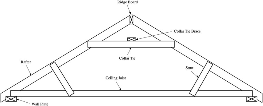
FIGURE 1. Sketch of a stick-built roof with all the members labelled.
The guidelines and regulations for stick-framed construction in Canada can be found in Section 9.23 of the National Building Code of Canada (NBCC 2020). The sections that can be applied to stick-built roof construction cover member spacing, maximum spans, connections between framing members, shaping of rafters, and ridge support. To ensure that all wood-framing done in Canada can be resilient against EF-2 tornadoes, the requirements must be improved.
Testing on stick-framed roofs in Canada goes back as far as 1954, when the then-recently-founded Division of Building Research decided to assess the structural integrity of conventional house construction under both wind and snow loads (Dorey and Schriever, 1957). Some of the current building code guidelines can even be traced back as far as 1963, when the Division of Building Research in Canada analyzed nailing patterns for conventional roof frames (Thorburn, 1963). This study also concluded that no failures occurred in any members during testing, indicating that there was not a balanced design between the strength of the connections of the roof frames and the framing members themselves. The building code requirements at the time involved wind loads of 1.9 kN/m2, for which the then-suggested nailing patterns’ strength sufficed. These loads are about half of those that are applied to the roof structure due to EF-2 tornado winds in this research.
There has been significant research on certain elements of the roof structure, such as roof-to-wall connections (RTWC). Testing on toe-nailed RTWCs has shown that they fail in increments with the majority of damage occurring at the peak pressures with multiple peak values often being required for a connection to fail (Morrison and Kopp, 2011). However, this may not be the case for tornadoes due to their relatively short duration. In the Morrison and Kopp study, the reduction in capacity due to factors such as construction errors was also recorded, as well as the method of failure of the RTWCs. Load-sharing between RTWCs has also been studied (Henderson et al., 2013), as well as the effect of various parameters that lead to the failure of said RTWCs in wood-frame houses (Gavanski and Kopp, 2017), namely roof shape and openings in the wall, which alters internal pressures. A study with similar methodology as used in the current paper was conducted in 1999, using standards to calculate loads on a light-frame wood roof and assess the structural reliability, however it only assessed the RTWCs and none of the other connections within the roof structure (Rosowsky and Cheng, 1999).
There has not been an in-depth analysis done on all of the various connections and members in a stick-built roof structure under tornado wind loads. While some parts of wood-frame roofs that have been examined using non-linear finite element analysis (Navaratnam et al., 2020), it is possible that detailed performance has not been investigated since there can be upwards of 30 types of connections implemented in the construction of a single house (Pan et al., 2014). This leads to challenges because of the level of complexity required to accurately simulate the nonlinear behaviour of these connections.
One of the first uses of finite element modelling for research relating to wind loading on full wood-frame roofs was in 1989, when the jump from simpler structural models for individual roof trusses to a full three-dimensional roof model of interconnected trusses was made to find the effects of load sharing (Cramer and Wolfe, 1989). Another three-dimensional model of a gable roof was created to study the failure of connections under hurricane wind loading, namely RTWCs modelled using non-linear elements defined using load-displacement relationships found in test data (Pan et al., 2014). More recently, a three-dimensional building model was created to showcase the load paths, as well as the load sharing, from wind loads in a wood-frame house, using non-linear connections (He et al., 2019). With this methodology, the authors were able to capture some of the failure methods commonly observed in post-disaster damage surveys, and have since expanded on their research by modelling tie connectors for the RTWCs (He et al., 2018).
For finite element models developed to predict the behaviour of wood-frame houses, non-linear springs have been the most commonly implemented element to represent connections between various roof components (Dao and van de Lindt, 2008; Kumar et al., 2012). The use of non-linear elements in full three-dimensional roof models can lead to the performance-based design concept of wood-frame roofs. The definition of non-linear link elements to define framing-to-framing connections has been implemented before in finite element models pertaining to wood-frame roofs (Asiz et al., 2009). This definition uses load-displacement data to define the translational spring properties of each framing connector, a similar approach to the link definition used in the finite element model depicted in this research. Roof frame members in the aforementioned papers are most commonly defined using linear isotropic three-dimensional frame elements, with sheathing panels defined using shell elements with linear orthotropic material properties.
1.3 Observations from damage surveys
Tornado damage surveys give the opportunity to retroactively evaluate the wind speeds of the tornado by looking at the damage to structures and comparing it to damage indicators on the Enhanced Fujita Scale (EF-Scale) for rating tornado intensities (Mehta, 2013). Initially proposed in 1971 (Fujita, 1971), it has since been modified by researchers to alter inconsistencies with respect to the damage indicators and estimated wind speeds associated with them (Texas Tech University, 2006). Recommendations have also been made for its application specifically in Canada (Sills et al., 2014). These modifications include a wider variety of damage indicators relating to structures and other objects to more accurately assess the wind speed of a tornado after the event has occurred.
With regards to structural failures in stick-built roofs, the failures most commonly occur from a lack of members in the roof, or connections that are either missing nails or are not sufficiently adequate to resist the wind loads from the tornado. There are several clear indications that a roof structure is stick built: a lack of connector plates for trusses, individually nailed connections, or ceiling joists remaining on the structure even after the roof has been removed, as shown in Figure 2A.
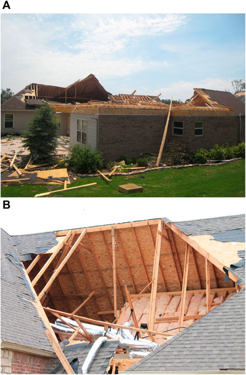
FIGURE 2. (A) Ceiling joists remaining in place after roof structure is removed (Joplin, Mo., 2011; courtesy of Dr. David Prevatt). (B) Stick-framed roof with a clear lack of members (Joplin, Mo., 2011; courtesy of Dr. David Prevatt).
There are a variety of images in which the roof structure clearly lacked sufficient members or connections to be structurally competent in high-wind events. A stick-framed roof using fewer members in the roof structure means the existing members are under a higher load demand. Clearly, the use of fewer members results in fewer connections within the roof structure. This creates relatively larger tributary areas for both the connections and members, which increases the load demand on these elements. Photos often show the difference in damage between a stick-built roof and a prefabricated roof that are situated near each other. The stick-built roofs will fail entirely, leaving just the ceiling joists attached to the rest of the structure, whilst the roof constructed with prefabricated trusses remains largely intact. Figure 2B shows a roof failure that exposes a clear lack of members in the roof with a large interior area.
A recurring issue with both stick-frame and truss-roof construction is the failure of the roof-to-wall connections. These connections resist the entire uplift of the structure and are commonly the initial point of failure in any wood-framed roof. Sheathing is also a weak point in roofs (however, it is not structurally analyzed for failure in the present paper). Both these failure modes need to be addressed, and this paper addresses the RTWC component, amongst any additional stick-framing improvements.
Damage survey photos with exposed connections often show that the construction was done using an insufficient number of nails or other connectors when compared to the local building codes or other connections within the same structure. Inconsistencies in nailed connections are a common occurrence in stick-framing, as hundreds of nails have to be used to connect members throughout a roof, which can lead to misplaced nails, leading to roof failures at those locations (Hong and He, 2015). Photos examined in a paper in 2017 (Kopp et al., 2017) show roof-to-wall connections composed of only one nail, instead of the code-required three in Canada.
The information gathered by damage survey photos can be used to find recurring issues with framing and connections to come up with solutions to address those problems. The damage survey images included in this section have shown a lack of consistency when it comes to stick-framing, which stems from an insufficiently detailed sections on stick-framing in building codes that are not engineered for high-wind events.
The objective of this research is to develop engineered stick-framing guidelines that can be easily utilized by builders to improve the resilience of light-frame wood roof structures against loads that can occur during an EF-2 tornado. The savings from insured damages, as well as the injuries and deaths avoided are the dominant driving forces behind the research. The guidelines this research comes up with will also have the goal of being easily implementable in the field, using a minimal variety of materials to limit construction errors.
2 Methodology
2.1 Approach
To accomplish the objectives, a stick-framed gable roof is modeled using SAP 2000. To predict failure modes under wind uplift, the non-linear three-dimensional finite element model defines the physical properties of every connection and member. Following the performance-based design concept, the loads are applied incrementally to the model, and the location of first failure is identified then retrofitted with different nailing patterns, connectors, or larger members, as appropriate. Sets of analyses are conducted iteratively until the performance target is reached.
2.2 Structural model
To achieve the objectives following a performance-based design approach, it is necessary to have a finite element (FE) model representative of a stick-built roof. Examining the demand on the individual elements, obtained from the FE model, and comparing them to the capacities defined from test data make it possible to find the modes of failure for which the roof structure needs to be improved.
There are three main components of the model to be defined, namely the connections between framing members, the framing members themselves, and the sheathing panels. There are a variety of connection properties defined for pull-out and shear resistance for the various nailing patterns and ties. The frame members initially all use SPF (Spruce-Pine-Fir) No.1/No.2 light structural framing members, while the sheathing panels all use the same material, OSB (oriented strand board).
Each frame-to-frame connection in the model is defined using a multi-linear plastic link. To implement this two-node link, a double node concept has been utilized, with a user-defined 10 mm gap to define the length of the connecting links, which have fixed rotational degrees of freedom. The three degrees of freedom that represent the axial and both shear directions must be defined for each specific connection. Figure 3 displays how SAP2000 uses the axial and shear degree of freedoms to connect joint i to joint j for a non-linear link element.
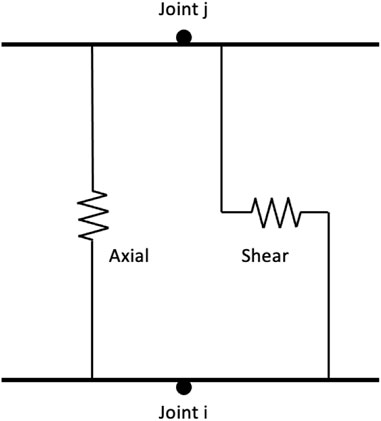
FIGURE 3. Sketch of axial and shear springs within a non-linear link [after CSi America (2014)].
The axial and shear directional properties of the non-linear links were defined using a combination of code values for capacities and test data for non-linear load-deformation curves. Calculations following CSA O86-14 are completed for all connection types, and are summarized in Table 1. The design values for connection capacity in both axial and shear values are significantly lower than the capacities found in test data for both face-nailed and toe-nailed connections, by up to a factor of 6 when comparing the axial resistance for toe-nailed connections (Riley and Sadek., 2003; Morrison and Kopp 2011) as required by CSA O86. Using the code-required design values is appropriate since the goal of this research is to improve the stick-built regulations found in building codes. This results in a safer design, due to safety factors. This addresses the potential uncertainties in the limit state and follows a performance-based design approach that meets code requirements. Due to this, experimental results may have failures in the same connections at higher loads; however, the sequence of failures would be consistent.
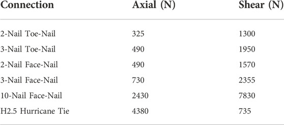
TABLE 1. Design capacities of connections.
The definition of the non-linear connection curves are based on test data. For face-nailed connections, single-nail withdrawal curves are used as a guide to re-create the force-displacement curves in the axial and shear directions. For toe-nailed connections, the same process is completed with toe-nailed test data. The curve for toe-nail withdrawal data followed test data from a 2003 study (Riley and Sadek, 2003), with the idealized curve defined in SAP2000 using the calculated capacity.
As shown in Figure 4, the yield and ultimate capacity points are taken at the locations of the average displacement from the test data, which in this case occur at 1 mm and 7 mm, respectively. The softening phase of the curve is not included in the link definitions as the location of first failure is all that is being noted, with no intent to capture the post-failure behaviour. This also provides greater numerical stability and faster convergence for the model. Hurricane ties may also be used for connections under significant load. The capacities of the ties used in the finite element model are taken from test data (Reed et al., 1997). A similar definition is used as for the nailed connections, using a load-deformation curve from hurricane tie testing (He et al., 2018).
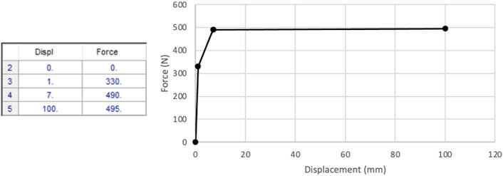
FIGURE 4. Load-deformation curve data points for 3-nail toe-nailed connections in model.
To represent the framing members in the stick-built roof, the SAP2000 model uses three-dimensional frame elements where the material geometric and physical properties are defined as 2 × 4 (38 × 89 mm) and 2 × 6 (38 × 140 mm) SPF No.1/No.2 members. To define the SPF No.1/No.2 properties in SAP 2000, orthotropic directional symmetry is chosen, which requires the definition of directional properties of wood. The capacities of the 2 × 4 and 2 × 6 member sizes in bending, shear, and tension, are calculated using specified strengths from the Canadian Wood Design Manual for structural light framing. The member capacities of all member grades and sizes are summarized in Table 2.

TABLE 2. Design capacities of members.
Sheathing panels are defined to ensure the model accounts for their bending rigidity, as they are present in virtually all residential roof structures. The sheathing panels are defined using thin shell elements, with a membrane thickness of 11.125 mm (7/16 in.), a common size. Similarly to frame elements, orthotropic material directional symmetry was used. The capacity of the sheathing panels was not calculated as they were not examined for failure in the model. The scope of the failures examined in the research were limited to the specific stick-framing practices since the performance of sheathing panels has been examined in the literature (Lee and Rosowsky, 2005).
To create the model, the members are all drawn on a pre-defined grid and then connected to each other using the two-node link elements previously described. Rigid links are only used where necessary to connect members together whose center-lines are slightly off-set. Meshing analysis was completed for the sheathing panels to ensure accurate results. The frame elements used auto-mesh to match the meshing of the area elements where applicable.
2.3 Loads
The loading in this study partially follows the American Society of Civil Engineers Standard (ASCE 7-22) for wind loading and the National Building Code of Canada (NBCC 2020) for snow loading. The tornado wind loads applied were calculated using the same method as the CSA S520:22 standard, which this research aims to supplement. The various load cases were chosen to test the limits of the structural components and connections with regards to uplift on the roof, shear across the structure and snow loading. Four Main Wind Force Resisting System (MWFRS) load cases were applied to the roof, following Chapter 27 and Chapter 28 of ASCE 7-22, as well as Components and Cladding (C&C) loading from Chapter 30 applied to the tributary areas of connections being targeted. These load cases have high internal positive internal pressures, assuming wall damage has occurred. A load case with snow loads must be applied as well to test the member and connections’ resilience in the opposite direction from the previous cases. All of the load cases include the dead weight of the structure, which is composed of the Spruce-Pine-Fir (SPF) members and Oriented Strand Board (OSB) sheathing panels. The connections, albeit small, are defined as weightless.
Wind loading must be applied following various assumptions and, therefore, it is important to note the characteristics of wind in the atmospheric boundary layer and wind in tornado events to properly apply realistic loading on a gable roof model. This research includes several assumptions for applying tornado loads using the same approach as laid out in ASCE 7-22. The static pressure drop in tornadoes and aerodynamic effects are relatively small in larger tornadoes for small buildings (Kopp and Wu, 2020). However, the wind profile effects are significant with maximum wind speeds occurring very close to the ground (Wurman and Kosiba, 2018). ASCE 7-22 accounts for this using a flat velocity profile all the way to the ground with no terrain roughness adjustments.
The wind speed chosen for load calculations, 135 miles per hour, is the upper end of the EF-2 tornado wind speed. The wind directionality factor, Kd, is taken as 0.80 from the updated ASCE 7-22. The exposure category selected is C. The velocity pressure exposure coefficient, Kz, is assumed to be 1, following common practice for EF-2 tornado design. The load combinations from NBCC, as shown later in this section, use a 1.0 factor for wind instead of the 1.4 factor otherwise used due to the wind load being based on an explicit tornado wind speed.
After the uplift capabilities of the structure are tested against wind loading, a load case with snow loads must be checked as well. The snow and rain loads taken for the snow load calculation were the 90th percentile loads of all locations given in the NBCC. The loads applied encompass all cities and towns of notable size in Canada, with the final 10% of towns not accounted for being located in rural and/or northern areas. This ensures that the proposed recommendations are applicable for virtually all new construction in Canada. The load cases are summarized in Table 3.
TABLE 3. Load cases applied to the finite element model.
The load combinations used, taken from NBCC 2015, are:
• Case 3: 1.25D + 1.5S
• Case 4: (1.25D or 0.9D) + 1.0W
• Specified Loads: D = Dead, S = Snow, W = Wind
Case 4 above uses the 0.9 multiplier for the dead load, as that gives a higher uplift load on the structure. The load combinations including both snow and wind companion loads have been omitted, since the wind loads of an EF-2 tornado would not be concurrent with snow loading.
In the model, all loads are applied to the sheathing area elements, which are connected directly to all of the rafters throughout the structure, and the loads are transferred from the sheathing uniformly to the frames. The loads acting on the ends of the gable roof laterally are applied to the structure using vertical OSB sheathing panels. The loading was applied using a nonlinear, direct-integration time-history for wind loads and a nonlinear, multi-step static approach for both dead and snow loads. The non-linearity of the analysis types has to mirror the non-linearity of the model’s connections themselves to be functional. The time history wind load is defined with 100 output time steps over the course of 10 s using a ramping load, which allows for a precision analysis to determine which connections or members fail first. These failed elements are then improved and the ramp load is applied again to the updated model to find the next location of failure.
2.4 Validation of model
For the validation of the non-linear finite element model, three different checks were conducted to verify the functionality and response of the model. The first is an individual validation done for a single defined connection. This was achieved by applying incremental uplift and shear ramp loading to ensure the link was reacting properly in a nonlinear fashion at the component level similar to experimental results obtained from the literature. Additionally, loads were applied such that the links remained in the linear range and the results were compared to static equilibrium calculations. Numerical results show strong agreement with hand calculations from static equilibrium for all checked connections. Two sets of analyses were then completed to validate the entire three-dimensional gable roof structure. Due to the redistribution of the loads between connections based on relative stiffness, different methods were followed for the validation completed at both the global and local (connection) levels. At the global level, the validation consisted of applying uplift loads and ensuring the sum of the forces resisted at the roof-to-wall connections is the same as the sum of the uplift loads applied. There was a 0.046% difference in the uplift applied when compared to the forces restrained at the RTWCs, which shows a strong agreement. This ensured global convergence of the numerical model at each time step and validated the global behaviour. Validation was also conducted at the component level to check the reactions of connections. Due to a lack of experimental data available analyzing the failure of all types of connections in a stick-framed roof structure, validating the model was based on the relative stiffness between connections and how the load was redistributed past the yielding point of the nail’s nonlinear range. A relative stiffness approach was followed rather than a quantitative validation for each link individually. This gave accurate force estimates in locations where many connections are located in close proximity, namely the RTWC areas where the rafter RTWC, ceiling joist RTWC and ceiling joist to rafter connections. Finally, a check was completed to ensure the effective load transfer to connections based on their tributary area. A load was applied in the same fashion as a components and cladding load would be applied, to the tributary area of a single connection, and the forces observed in the connection were then compared to the forces applied to ensure the load path in the model was functional. Overall, the validation of the model through comparison to past tests is challenging, as there is no completed research that uses similar gable roof configurations and stick-framing techniques. Roof-to-wall connections and other nailed connections throughout the roof structure are defined to act in a similar fashion to the non-linear connections described in the literature. Load-deflection curves from test data have been implemented for defining the non-linear behaviour of connections in finite element models presented in past research (He et al., 2018), although that was done using test capacities directly. For validation purposes, the RTWCs in the model were first defined using test data. This ensured that the defined connections were acting similarly to the test data before reducing the connections’ capacities to match code capacities for the performance-based design analysis. The comparison between test data and the model load-deformation curves before reducing connection capacity is shown in Figure 5. It can be noticed from this figure that the model accurately captures the nonlinear behavior of the connection both in axial and shear. The results from the model are perfectly matching test data except for the softening branch which has not been considered in the implementation of the link properties for faster convergence since the scope of this study is not focusing on the post-failure behavior. This validation was done for a single connection as well as for the complete three-dimensional model. Furthermore, to validate that the model results consider the load sharing between the connections, another comparison is done as shown Figure 6. The results shown in this figure indicate that connections in different locations in the roof experience different demands, as should be expected based on the load patterns applied. For example, at an instantaneous time step where the first failure is noticed in the RTWC at the gable end other connections near the middle of the roof structure might be still within the linear range demand. This validates that the model accurately predicts the load sharing between connections.
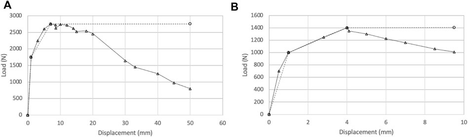
FIGURE 5. Load-deformation curves taken from test data [Riley and Sadek, (2003)] △, plotted alongside load-deformation curves of the same defined connections from post-analysis ○: (A) RTWC Axial; (B) RTWC Lateral Shear.
FIGURE 6. Load sharing from post-analysis data, showing the defined load-deformation capacity of the RTWC in the axial direction △, the load taken by the RTWC at the gable end frame ○, and the load taken by the RTWC at the 11th inner frame □.
A post-analysis validation was also conducted using damage survey images. The primary failure mode observed in the model matched the most common failure mode in damage survey images, the failure of the rafter roof-to-wall connection. This connection has been studied due to its susceptibility to early failure during high-wind events in the past as well (Amini and van de Lindt, 2014; Gavanski and Kopp, 2017). A mesh sensitivity analysis was completed for the shell elements modelling the roof sheathing, and the frames used matching mesh sizes to connect between the two elements. This analysis ensured accurate results independent of mesh size, and was done until two successive mesh sizes gave similar results with a reasonable analysis time.
3 Results
The first iteration of the model structure follows the 2020 NBCC requirements in Section 9.23. Figure 7 displays the labels of all the connections and members used in the roof structure, with Table 4 summarizing the initial connections used. Using a performance-based design approach, the locations of failure are identified and upgraded sequentially until the structure does not fail under EF-2 tornado loads. Demand-capacity (D/C) ratios are recorded throughout the design process to check for the failure of various elements used in the gable roof structure. The concept and application of D/C ratios in this performance-based design approach are based on past wood-frame research (Stevenson et al., 2018). Final recommendations and D/C ratios of all elements of the last iteration are provided.
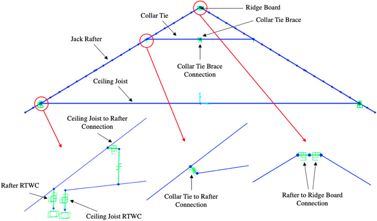
FIGURE 7. Definition of all members and connections in the initial model.
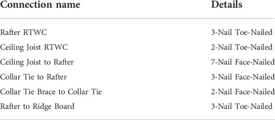
TABLE 4. Connections used in the first model iteration, following NBCC 2015.
Failure herein is defined as the D/C ratio
With the RTWCs being such weak points in the design, it is clear that the structure would benefit from more RTWCs being added to the roof. This can be done by adding connections between the gable end frames and the walls below, essentially giving the gable roof four sides with RTWCs, similar to hip roofs. Adding vertical members connecting the rafters to the bottom of the gable end frames and adding RTWCs to the bottom of the gable frame will transfer a significant portion of the load through the gable end frames rather than all of the load going through the rafters to the rafter and ceiling joist RTWCs.
Improving the gable end frames is also beneficial to many other connections and members throughout the structure, as the maximum demand in the initial model is often found at the gable end frame for structural elements. Analyzing early results, before improving the gable end frames, indicate the need for this alteration to be completed. Below, the D/C ratios of the model layout with struts and various improved connections are plotted from all frames within the structure to compare the demand on the gable end frame against the demand on other frames in the roof. The results, shown in Figure 8; Figure 9, indicate that the majority of structural elements undergo their largest D/C ratio at the gable end frame location.
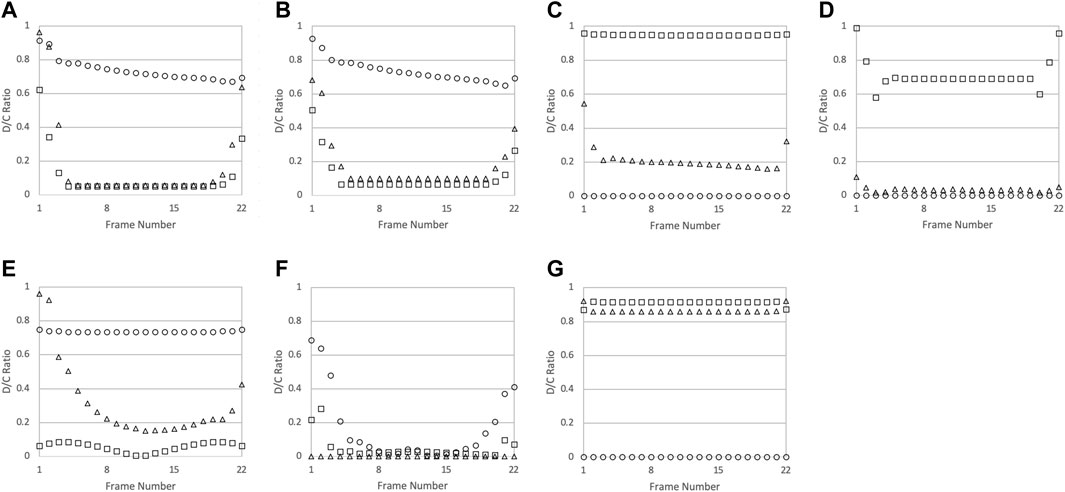
FIGURE 8. The D/C ratios of the connections throughout the roof structure: (A) Rafter RTWC; (B) Ceiling Joist RTWC; (C) Ceiling Joist to Rafter; (D) Collar Tie to Rafter; (E) Rafter to Ridge Board; (F) Collar Tie Brace to Collar Tie; and (G) Strut to Rafter & Ceiling Joist. Each connection has D/C ratios shown for the axial direction ○, and each shear direction △, □. Frame numbers 1 and 22 indicate the gable end frames.
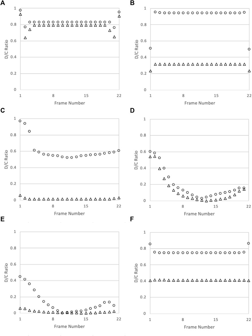
FIGURE 9. The D/C ratios of the frames throughout the roof structure: (A) Rafter; (B) Ceiling Joist; (C) Collar Tie; (D) Ridge Board; (E) Collar Tie Brace; (F) Strut. Each member has D/C ratios shown for moment ○ and shear △. Frame numbers 1 and 22 indicate the gable end frames.
To improve the gable end frames, inspiration was taken from Section 6.3.1 of CSA S520, Gable Roofs (Canadian Standards Association Group, 2022). This includes both specified gable end framing, including gable end bracing, and using hurricane ties as RTWCs. Hurricane ties are used at all RTWC locations in the roof structure. H2.5 hurricane ties from Simpson Strong-Tie are used. These are added to the connections for all RTWCs and was chosen since it adequately resists the uplift, as well as being commonly implemented and inexpensive. The H2.5 tie can also be added to a toe-nailed connection, which is required since the shear capacity of the tie is low.
With the addition of the RTWCs and gable end framing specified above, the model is once again run to analyze the need for improvement of other elements. Noted locations that had high initial D/C ratios are the collar tie to rafter connection and the size of the rafter member. The moment in the members can be significantly reduced by adding struts one-third of the way up the rafters that connect to the ceiling joists below. After the inclusion of the struts, the additional changes required to resist wind loads are summarized in Table 5, starting with the first element to fail and continuing in order of failure.
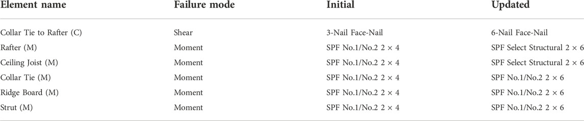
TABLE 5. All of the updated connections (C) and members (M) due to wind loading in order of failure.
Additional changes are considered due to the snow load case. The weight of the snow on the roof combined with the dead load of the structure created the worst-case loading scenario for a few of the elements. The changes required to these elements are shown in order of first failure to last in Table 6. All of these are in addition to the improvements required to withstand the wind loading of the EF-2 tornado.
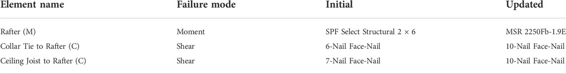
TABLE 6. All of the updated connections (C) and members (M) due to snow loading in order of failure.
In summary, the wind load cases are responsible for the design of both of the RTWCs, as well as the ceiling joist, collar tie, and ridge board members. The snow load case has the largest effect on the rafter members and the connections that attach the rafter to other members, namely the collar tie-to-rafter and ceiling joist-to-rafter connections. The high forces in the gable end frames make it critical to change the layout of those frames. Adding more RTWCs ensures that the extreme load demand on the edge of the roof structure and the overhang are effectively dealt with. The demand-capacity ratios for all elements in the final recommended structure are included to show locations near design capacity. The D/C ratios are calculated using the maximum demand on the connection or member at any location within the roof structure for any load case. Table 7 shows the D/C ratios of the connections and Table 8 shows the D/C ratios for all members in the structure.
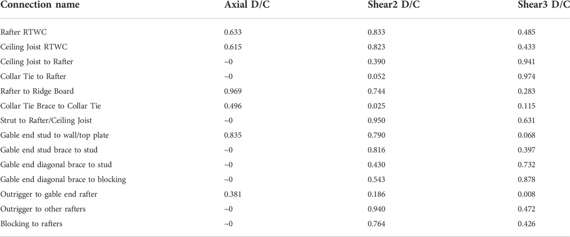
TABLE 7. Final D/C ratios of the connections.
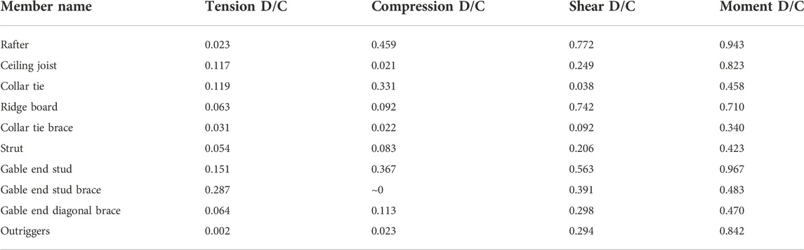
TABLE 8. Final D/C ratios of the members.
There are a significant number of D/C ratios exceeding 0.9, which is due to the elements being designed to withstand the applied loads, but without being over-designed. Every connection requires the specified number of nails. The safety factors applied in the calculations for the capacities of the connections ensure that they are structurally capable regardless of the high demand/capacity ratios shown above.
4 Discussion
Comparing the failure of elements observed in the model to damage survey photos of stick-framed roofs indicate the weak points in the current practice. The RTWCs are the connections that were the most over-capacity in the model. This aligns with many damage survey photos which show that the entire roof structure has been lifted off the wall plates. This is by far the most common failure mode observed from all the stick-built roof failures analyzed. In these images, the rafter RTWCs failed more often than any other connection in the frame. The connection between the rafter and ceiling joist also failed, allowing for the removal of the entire roof. The recommended 7-nail connection between the ceiling joists and rafters is often seen in structures as constructed using only 3 nails, which makes it unsurprising that the ceiling joists remain attached to the walls after the rafter RTWCs fail. As seen from the initial model data, collar tie to rafter connections are also a highly likely location of failure. Figure 2B shows the removal of half the roof, indicating the failure of not just the RTWC, but also the collar tie to rafter connection, as many collar ties can still be seen on other non-failed frames. The collar tie to rafter connections were, after both RTWCs, the most altered connection from the model, with seven additional nails required to resist the load demand. This indicates another failure mode that can be explained with the model’s results. The recommendations that this research suggests are visualized in a damage survey photo in Figure 10 and in a schematic in Figure 10.
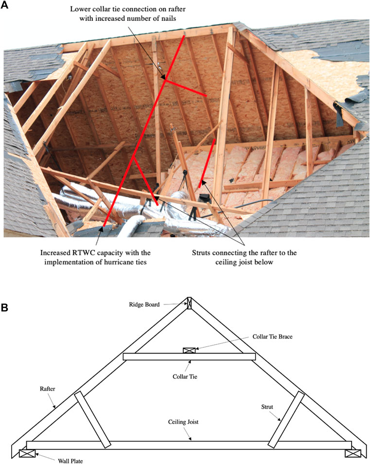
FIGURE 10. (A) Thesis recommendations highlighted on a damage survey photo. (B) Visualization of the thesis recommendations for the damaged roof structure.
Due to the early failure of RTWCs in stick-framed roofs, it is hard to discern the order of failure of many of the remaining connections based solely on the damage survey photos, as they would not be able to fail after the removal of the roof structure. Any damages that would be visible on a removed roof structure could also possibly not be from wind loads, but also from impact with the ground or other objects.
5 Final discussion and conclusion
The results show that existing guidelines are inadequate for tornado loads, calculated following a similar method to CSA S520. The improvements identified herein touch upon almost all of the connections in the stick-built roof structure, and bring up the need to recommend member sizes and strengths in order to achieve resistance to EF-2 wind loads and significant snow loads.
The final recommendations for stick-built roof framing are shown in Figures 11–13. These recommendations cover all aspects of the framing, the repeated inner framing connection and member layout, the gable end frame specifications, as well as the outrigger framing. Following this is a list of additional specifications not shown in Figures 11–13.
• All nails, unless otherwise specified, are 3.33 mm diameter x 76 mm length
• The repeating inner frames are to be spaced at no more than 600 mm on centre
• All gable end studs are to be oriented with their strong axis perpendicular to the face of the gable end frame
• Diagonal gable end bracing does not need to be added within 1,200 mm of the edges of the gable end frame
• Blocking is not required between any rafters that do not have a brace attached in their bay or are adjacent to such a rafter
• Gable end studs are to be braced horizontally if they exceed 1800 mm in height
• Outriggers shall extend at least as long as the cantilevered distance inwards (ie. to the first rafter inwards if cantilever is 600 mm)
• The rafter to ridge board connection can use one of the rafter hanger options for increased strength and longevity
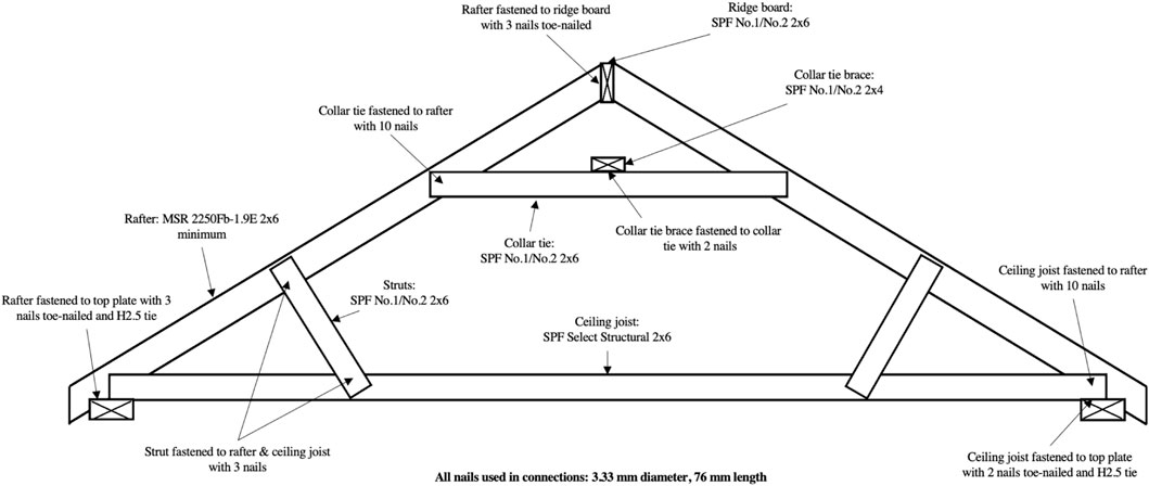
FIGURE 11. The recommended connections and members in the repeating inner frame.
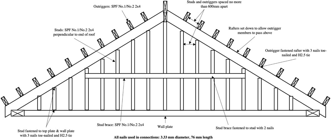
FIGURE 12. The recommended connections and members in the gable end frame.
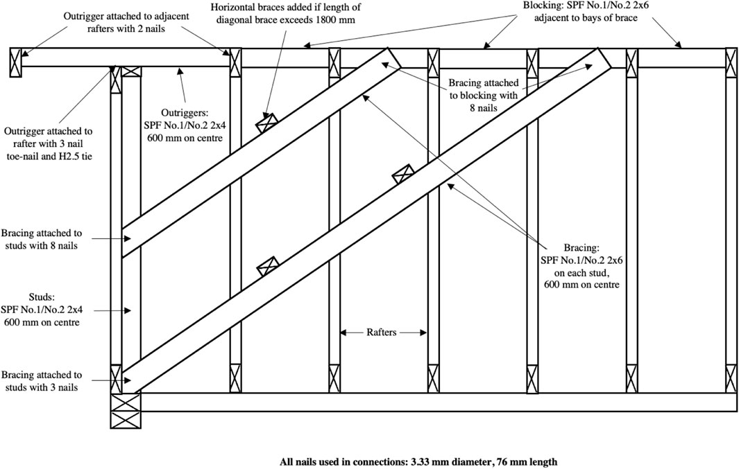
FIGURE 13. The recommended connections and members in the outrigger framing and bracing (after CSA S520).
The three-dimensional numerical model used in this research effectively imitated the reaction of a stick-framed roof structure due to the use of test data to define the non-linear aspect of all nailed connections. Being able to analyze all frames in the roof at once ensured the first locations of failure were recognized and improved upon with ease.
This research helps to close the knowledge gap for stick-framing construction with respect to tornado loads. Using some similar design aspects to trussed roof structures, there is now a feasible design resistant of tornado loads up to the EF-2 level. Other roof shapes and sizes to be considered can be analyzed following a similar methodology as depicted in this research, filling out the remaining gaps in stick-framing tornado design.
Data availability statement
The raw data supporting the conclusions of this article will be made available by the authors, without undue reservation.
Author contributions
CB is a MESc student under the co-supervision of GK and AEA. The research discussed the work completed for the Master’s thesis. The topic had previously been conceived by GK and AEA, with the approach to the work being a collaboration by the authors once all were involved. All analyses and interpretation of data results were conducted by CB, as well as the manuscript drafts, under the supervision of GK and AEA. GK and AEA additionally advised the design choices and results interpretation, as well as the manuscript to be published. The authors agree to be accountable for all aspects of the research in ensuring that questions related to the accuracy or integrity of any part of the work are appropriately investigated and resolved.
Funding
This work was funded by the Natural Sciences and Engineering Research Council (NSERC) of Canada through the Discovery Grants program.
Acknowledgments
GK gratefully acknowledges financial support from ImpactWX and Western University. The authors are grateful for many helpful conversations with Mr. Brent Bunting, Mr. Kevin Rocchi, and Ms. Sarah Stevenson.
Conflict of interest
The authors declare that the research was conducted in the absence of any commercial or financial relationships that could be construed as a potential conflict of interest.
Publisher’s note
All claims expressed in this article are solely those of the authors and do not necessarily represent those of their affiliated organizations, or those of the publisher, the editors and the reviewers. Any product that may be evaluated in this article, or claim that may be made by its manufacturer, is not guaranteed or endorsed by the publisher.
References
Amini, M. O., and van de Lindt, J. W. (2014). Quantitative insight into rational tornado design wind speeds for residential wood-frame structures using fragility approach. J. Struct. Eng. (N. Y. N. Y). 140, 04014033. doi:10.1061/(asce)st.1943-541x.0000914
Asiz, A., Chui, Y. H., Smith, I., and Zhou, L. (2009). Development of advanced system design procedures for the canadian wood design standard. Wood Sci. Tech. C., Fac. For. Environ. Manag. UNB 142, E4014003.
Atkins, N. T., Butler, K. M., Flynn, K. R., and Wakimoto, R. M. (2014). An integrated damage, visual, and radar analysis of the 2013 moore, Oklahoma, ef5 tornado. Bull. Am. Meteorol. Soc. 95, 1549–1561. doi:10.1175/bams-d-14-00033.1
Bouwer, L. M. (2019). “Observed and projected impacts from extreme weather events: Implications for loss and damage,” in Loss and damage from climate change (Berlin, Germany: Springer), 63–82.
Canadian MortgageHousing Corporation (2014). Canadian wood-frame house construction. 3rd edn. Canada: Government of Canada.
Canadian Standards Association Group (2022). Csa S520:22. 1st edn. Mississauga, ON: Canadian Standards Association Group.
Cramer, S. M., and Wolfe, R. W. (1989). Load-distribution model for light-frame wood roof assemblies. J. Struct. Eng. (N. Y. N. Y). 115, 2603–2616. doi:10.1061/(asce)0733-9445(1989)115:10(2603)
CSi America (2014). “Sap2000 link information,” in Computers and structures, inc. - technical knowledge base (Walnut Creek, CA: CSi America).
Dao, T. N., and van de Lindt, J. W. (2008). New nonlinear roof sheathing fastener model for use in finite-element wind load applications. J. Struct. Eng. (N. Y. N. Y). 134, 1668–1674. doi:10.1061/(asce)0733-9445(2008)134:10(1668)
Dorey, D. B., and Schriever, W. (1957). “Structural test of a house under simulated wind and snow loads,” in Symposium on full-scale tests on house structures, 29–49.
Ellingwood, B. R., Rosowsky, D., Li, Y., and Kim, J. H. (2004). Fragility assessment of light-frame wood construction subjected to wind and earthquake hazards. J. Struct. Eng. (N. Y. N. Y). 130, 1921–1930. doi:10.1061/(asce)0733-9445(2004)130:12(1921)
Elsner, J. B., Fricker, T., and Schroder, Z. (2019). Increasingly powerful tornadoes in the United States. Geophys. Res. Lett. 46, 392–398. doi:10.1029/2018gl080819
Emanuel, K. (2005). Increasing destructiveness of tropical cyclones over the past 30 years. Nature 436, 686–688. doi:10.1038/nature03906
Fujita, T. T. (1971). Proposed characterization of tornadoes and hurricanes by area and intensity. Illinois, United States: NTRS.
Gavanski, E., and Kopp, G. A. (2017). Fragility assessment of roof-to-wall connection failures for wood-frame houses in high winds. ASCE-ASME J. Risk Uncertain. Eng. Syst. Part A Civ. Eng. 3, 04017013. doi:10.1061/ajrua6.0000916
He, J., Pan, F., Cai, C., Habte, F., and Chowdhury, A. (2018). Finite-element modeling framework for predicting realistic responses of light-frame low-rise buildings under wind loads. Eng. Struct. 164, 53–69. doi:10.1016/j.engstruct.2018.01.034
He, J., Pan, F., and Cai, C. (2019). Modeling wind load paths and sharing in a wood-frame building. Wind Struct. 29, 177–194.
Henderson, D. J., Morrison, M. J., and Kopp, G. A. (2013). Response of toe-nailed, roof-to-wall connections to extreme wind loads in a full-scale, timber-framed, hip roof. Eng. Struct. 56, 1474–1483. doi:10.1016/j.engstruct.2013.07.001
Hong, H., and He, W. (2015). Effect of human error on the reliability of roof panel under uplift wind pressure. Struct. Saf. 52, 54–65. doi:10.1016/j.strusafe.2014.07.001
Kopp, G. A., Hong, E., Gavanski, E., Stedman, D., and Sills, D. M. (2017). Assessment of wind speeds based on damage observations from the angus (ontario) tornado of 17 june 2014. Can. J. Civ. Eng. 44, 37–47. doi:10.1139/cjce-2016-0232
Kopp, G. A., and Wu, C.-H. (2020). A framework to compare wind loads on low-rise buildings in tornadoes and atmospheric boundary layers. J. Wind Eng. Industrial Aerodynamics 204, 104269. doi:10.1016/j.jweia.2020.104269
Kuligowski, E., Lombardo, F. T., Phan, L., Levitan, M., and Jorgensen, D. (2014). Final report, national Institute of standards and technology (NIST) technical investigation of the may 22, 2011, tornado in Joplin, Missouri. Rep. NIST NCSTAR 3.
Kumar, N., Dayal, V., and Sarkar, P. P. (2012). Failure of wood-framed low-rise buildings under tornado wind loads. Eng. Struct. 39, 79–88. doi:10.1016/j.engstruct.2012.02.011
Lee, K. H., and Rosowsky, D. V. (2005). Fragility assessment for roof sheathing failure in high wind regions. Eng. Struct. 27, 857–868. doi:10.1016/j.engstruct.2004.12.017
Mehta, K. C. (2013). Development of the EF-scale for tornado intensity. J. Disaster Res. 8, 1034–1041. doi:10.20965/jdr.2013.p1034
Morrison, M. J., and Kopp, G. A. (2011). Performance of toe-nail connections under realistic wind loading. Eng. Struct. 33, 69–76. doi:10.1016/j.engstruct.2010.09.019
Navaratnam, S., Ginger, J., Humphreys, M., Henderson, D., Wang, C.-H., Nguyen, K. T., et al. (2020). Comparison of wind uplift load sharing for Australian truss-and pitch-framed roof structures. J. Wind Eng. Industrial Aerodynamics 204, 104246. doi:10.1016/j.jweia.2020.104246
Pan, F., Cai, C., Zhang, W., and Kong, B. (2014). Refined damage prediction of low-rise building envelope under high wind load. Wind Struct. 18, 669–691. doi:10.12989/was.2014.18.6.669
Prevatt, D. O., Coulbourne, W., Graettinger, A. J., Pei, S., Gupta, R., and Grau, D. (2012). Joplin, Missouri, tornado of May 22, 2011: Structural damage survey and case for tornado-resilient building codes. Virginia, United States: ASCE, 1–47.
Reed, T., Rosowsky, D., and Schiff, S. (1997). Uplift capacity of light-frame rafter to top plate connections. J. Archit. Eng. 3, 156–163. doi:10.1061/(asce)1076-0431(1997)3:4(156)
Riley, M. A., and Sadek, F. (2003). Experimental testing of roof to wall connections in wood frame houses. Washington, D.C., United States: US Department of Commerce.
Rosowsky, D. V., and Cheng, N. (1999). Reliability of light-frame roofs in high-wind regions. i: Wind loads. J. Struct. Eng. (N. Y. N. Y). 125, 725–733. doi:10.1061/(asce)0733-9445(1999)125:7(725)
Sills, D. M., Kopp, G. A., Elliott, L., Jaffe, A. L., Sutherland, L., Miller, C. S., et al. (2020). The northern tornadoes project: Uncovering Canada’s true tornado climatology. Bull. Am. Meteorological Soc. 101, E2113–E2132. doi:10.1175/bams-d-20-0012.1
Sills, D. M., McCarthy, P. J., and Kopp, G. A. (2014). Implementation and application of the EF-scale in Canada. Madison WI: American Meteorology Society.
Simmons, K. M., Kovacs, P., and Kopp, G. A. (2015). Tornado damage mitigation: Benefit–cost analysis of enhanced building codes in Oklahoma. Weather, Clim. Soc. 7, 169–178. doi:10.1175/wcas-d-14-00032.1
Smith, A. B., and Matthews, J. L. (2015). Quantifying uncertainty and variable sensitivity within the us billion-dollar weather and climate disaster cost estimates. Nat. Hazards (Dordr). 77, 1829–1851. doi:10.1007/s11069-015-1678-x
Stevenson, S. A., Kopp, G. A., and El Ansary, A. M. (2018). Framing failures in wood-frame hip roofs under extreme wind loads. Front. Built Environ. 4, 6. doi:10.3389/fbuil.2018.00006
Storm Prediction Center (2014). Storm prediction center wcm page. Available online at www.spc.noaa.gov/wcm.
Structural Engineering Institute (2022). Minimum design loads and associated criteria for buildings and other structures. 9th edn. VA: American Society of Civil Engineers.
Texas Tech University (2006). A recommendation for an enhanced fujita scale. Lubbock, Texas: Wind Science and Engineering Center (TTU WiSE), Texas Tech University.
Thorburn, H. J. (1963). Calculation and experimental check of a nailing schedule for conventional roof frames
Weston, J., and Zhang, W. (2017). Equivalent parameterized beam model for nailed connections in low-rise residential buildings. Eng. Struct. 145, 12–21. doi:10.1016/j.engstruct.2017.05.002
Keywords: light-frame wood construction, Enhanced-Fujita scale, tornadoes, gable roof, stick-framing, non-linear finite element modelling, building code, performance based design
Citation: Bain CLD, Kopp GA and El Ansary AM (2022) Design of stick-framed wood roofs under tornado wind loads. Front. Built Environ. 8:1029237. doi: 10.3389/fbuil.2022.1029237
Received: 27 August 2022; Accepted: 16 November 2022;
Published: 30 November 2022.
Edited by:
Arthriya Subgranon, University of Florida, United StatesReviewed by:
David James Henderson, James Cook University, AustraliaMingfeng Huang, Zhejiang University, China
Copyright © 2022 Bain, Kopp and El Ansary . This is an open-access article distributed under the terms of the Creative Commons Attribution License (CC BY). The use, distribution or reproduction in other forums is permitted, provided the original author(s) and the copyright owner(s) are credited and that the original publication in this journal is cited, in accordance with accepted academic practice. No use, distribution or reproduction is permitted which does not comply with these terms.
*Correspondence: Gregory A. Kopp , Z2Frb3BwQHV3by5jYQ==