 Hao Liu
 Jie Han
 Robert L. Parsons1
- 1Department of Civil, Environmental, and Architectural Engineering (CEAE), University of Kansas, Lawrence, KS, United States
Expansion and contraction of integral abutment bridges due to temperature changes force integral bridge abutments (IBAs) to move toward and away from the backfill, thus increasing horizontal earth pressures behind the abutments and inducing bending moments on pile foundations. This paper presents the state of knowledge and recent advances in understanding the behavior of IBAs in response to temperature changes including abutment movement, pile response, and horizontal earth pressure behind the abutment, examines the effect of bridge skew on the behavior, and discusses possible measures to mitigate temperature change-induced problems for IBAs. Field data show that both bending moments of piles near the bottom of abutments and axial loads of piles fluctuated with temperature. Redistribution of dead loads among bridge components due to planar temperature gradients and earth pressure changes behind the abutment contributed to axial load fluctuations in piles. Magnitude and distribution of horizontal earth pressures behind the abutment depend on factors such as abutment movement and abutment movement mode. Most of the current design methods overestimated the horizontal earth pressures at the bottom of the abutment during bridge expansion. Compressible inclusions placed behind the abutment, geosynthetic-reinforced backfill, and lightweight backfill in place of typical aggregate backfill are helpful to reduce horizontal earth pressures behind the abutment at high temperatures and temperature change-induced backfill settlements.
Introduction
Integral bridges can be classified into three types: 1) full integral bridge (i.e., bridge decks as components of the superstructure rigidly connected to abutments as a monolithic unit); 2) semi-integral bridge (bridge decks not rigidly connected to abutments); and 3) deck-extension bridge (bridge decks not connected to abutments but extending over abutments) (Weakley, 2005). This paper refers to full integral bridges as integral abutment bridges (IABs). Figure 1 shows the connections between superstructures and abutments of conventional bridges and IABs. In a conventional bridge, the bridge superstructure is simply supported by abutments or piers via movable shoes or hinged shoes (Tatsuoka et al., 2009) while the bridge superstructure in an IAB is rigidly connected to its abutments or piers to form a monolithic unit (Jorgenson, 1983). IABs have several advantages over conventional bridges including but not limited to: 1) lower total cost due to elimination of expensive material, and installation and maintenance of shoes; 2) better riding quality due to elimination of expansion joints; 3) more rapid and economical construction because of fewer piles required to support the abutment (Tatsuoka et al., 2009); 4) simpler design by simplifying the bridge superstructure, piles, abutments into a continuous frame structure (Burke, 1993); 5) higher seismic stability due to rigid connections between bridge superstructures and abutments; 6) smaller buoyancy loads during hurricanes and tsunamis due to thinner bridge superstructures (Tatsuoka et al., 2009); 7) larger resistance against uplift forces acting on the ends of bridge superstructures; and 8) more structural components to resist horizontal loads (e.g., braking forces). However, the inherent problems of IABs include: 1) relative movement (e.g., differential settlement between abutments and piers), inducing additional shear force and moment in the continuous frame structure; 2) seasonal and daily temperature changes, causing backfill settlements and aggravating bump problems (Liu et al., 2020); 3) expansion of bridge superstructures at high temperature, inducing bending moment in the bridge superstructure, and high horizontal earth pressures behind the abutment that cause large shear forces and bending moments to the abutment in turn; 4) horizontal displacements of piles induced by expansion and contraction of the bridge superstructure, reducing vertical bearing capacity of the piles and even causing yielding of the piles due to plastic hinging (Greimann and Wolde-Tinsae, 1998; Frosch et al., 2006); 5) contraction of bridge superstructures, resulting in rotation and cracking in wing walls (Wolde-Tinsae and Klinger, 1987); and 6) unbalanced moments in the horizontal plane if the horizontal loads from both abutments do not balance each other in skewed IABs (Burke, 1993). Abutment movements in IABs have caused most of the above inherent problems. Earth pressure, hydrostatic pressure, traffic, impact, wind, and seismic loading can all induce abutment movements in both conventional bridges and IABs. However, some factors, such as thermal (daily or seasonal) expansion and contraction of bridge superstructures, concrete shrinkage, and material creep, cause abutment movements in IABs (Ooi et al., 2010). Barker and Carder (2001) found that 85% of shrinkage and creep of bridge superstructures occurred approximately within the first 3 years after bridge construction. However, unlike thermal expansion and contraction that move the abutment toward and away from the backfill, shrinkage and creep only pull the abutment away from the backfill. Therefore, the contraction of bridge superstructures induced by shrinkage and creep of concrete may be more than the expansion of bridge superstructures at high temperatures for short-span IABs (Ooi et al., 2010). As a result, high horizontal earth pressures behind the abutment may not be an issue of concern for some short-span IABs.
FIGURE 1. Connection between bridge superstructure and abutment of: (A) conventional bridge and (B) integral abutment bridge.
Researchers and engineers have increasingly paid attention to the behavior of IABs, especially as a result of temperature changes. The performance of IABs depends on site characteristics and bridge geometries. For example, abutment movements in IABs depend on the type of abutment and the type of soil supporting the abutments. Darley and Alderman (1995) found that abutment rotation was the primary movement mode due to temperature changes when the abutment was supported by a spread footing seated on a strong soil. However, abutment translation was the dominating movement mode of the short abutment supported on steel H-piles, due to the expansion and contraction of the bridge superstructure (Kim and Laman, 2012). To understand the state of knowledge in IAB behavior and performance, this study conducted a comprehensive literature review including 33 monitored IABs and the relationship between air temperature and temperature in IABs. Based on the literature review, this paper summarizes the performance of IABs in response to temperature changes including 1) abutment movements; 2) horizontal earth pressures behind the abutment; and 3) pile responses, and discusses the effect of bridge skew. Furthermore, this paper presents recent advances in measures to mitigate temperature change-induced abutment problems, e.g., utilization of compressible inclusions, use of geosynthetics to reinforce backfill, and use of lightweight backfill.
Background and common practice of integral abutment bridges
In the late 1930s and early 1940s, the U.S. started to construct IABs, followed by the United Kingdom in the 1970s. In the United Kingdom and Ireland, IABs with a length up to 60 m and a skew not exceeding 30° are only permitted if there are no overriding reasons (British Highways Agency, 2003). The US Federal Highway Administration (FHWA) suggests the lengths of IABs should be less than 91, 152, and 183 m if bridge girders are steel, cast-in-place concrete, and prestressed or post-stressed concrete, respectively. However, IABs with a length up to 305 m are permitted in Louisiana, and a skew angle up to 45° is allowable in California and Nevada (Lan, 2012). Figure 2 shows the four types of integral bridge abutments classified by British Highways Agency (2003) including 1) frame abutment; 2) embedded abutment; 3) bank pad embankment; and 4) end screen abutment (typical for semi-integral bridges). The United Kingdom practice prefers the frame abutment because the bridge and the approach pavement are believed to settle equally, thus avoiding a differential settlement at the interface between the abutment and its adjacent pavement. According to a survey, Maruri and Petro (2005) reported that more than 70% of state agencies in the U.S. preferred to use embedded H-piles for their IABs. The reason for this preference is that H-piles allow abutments to translate and rotate easily in response to the expansion and contraction of bridge superstructures (White et al., 2010).
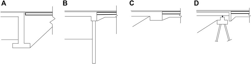
FIGURE 2. Types of integral abutments: (A) frame abutment; (B) embedded abutment; (C) bank pad abutment; and (D) end screen abutment [modified from British Highways Agency (2003)].
Table 1 presents the summary of 33 monitored IABs from a literature review. This table shows that steel H-piles (HP), concrete-filled steel tube (CFT) piles, spread footings (i.e., frame abutments), precast concrete (PC) piles, and prestressed precast concrete (PCC) piles are used to support the abutments in real projects. The dimensions of CFT are expressed as “outer diameter × thickness of steel tube.” For example, “0.356 m × 0.008 m” means the outer diameter of the CFT was 0.356 m and the thickness of the steel tube was 8 mm. Six IABs in Table 1 used shallow foundations to support their abutments and the maximum bridge length of these bridges was 60 m. Six IABs with lengths ranging from 33 to 110 m used concrete-related piles including CFT, PC, PPC piles to support their abutments, while the remaining 21 IABs with lengths ranging from 18.9 to 297 m used steel H-piles to support their abutments. Steel H-piles are susceptible to corrosion and carry applied loads mostly through their skin friction and/or end bearing (e.g., bedrock). As a result, steel H-piles are a good choice in stiff soils or where bedrock is close to the surface (Kamel et al., 1996), but concrete piles are a better choice than H-piles in a corrosion-susceptible and scour-susceptible environment (Ooi et al., 2010). In addition, concrete piles are a preferred alternative to steel H-piles where the length of the H-piles in sand and/or aggregate exceeds 30 m because the steel H-piles are expensive and impractical if they become too long. In addition, concrete piles with large cross-sections may densify soils during pile driving thus increasing the pile load capacity (Kamel et al., 1996). Based on a finite-element study, Civjan et al. (2007) observed that the backfill condition affected the performance of IABs predominantly when the bridge expanded at high temperatures, while the pile restraint condition affected the performance of IABs predominantly when the bridge contracted at low temperatures. As the IAB expanded, denser backfill increased abutment rotation, reduced pile moment, and increased horizontal earth pressures behind the abutment. In addition, less pile restraint increased horizontal earth pressures behind the abutment as the IAB expands. As the IAB contracted, less pile restraint reduced abutment rotation and pile moment.

TABLE 1. Summary of instrumented IABs in the field.
High horizontal earth pressures behind abutments are one of the design and performance concerns for IABs. Pressure relief systems have been adopted in IABs at times in the past. For example, the Cass County Bridge (Jorgenson, 1983) used corrugated metal plates to retain the backfill behind the abutment, and then placed vertical pressure relief strips between the abutment and the corrugated metal. When the bridge superstructure expanded, the strips were compressed, thus reducing the deformations of the backfill and the horizontal earth pressures behind the abutment. Compressive materials were glued to both sides of the web of H-piles in this bridge. This practice reduced the resistance of H-piles to longitudinal movements of the bridge. In addition to compressive materials, other measures have been commonly used to reduce the restraints from piles. For example, placing a corrugated polythene pipe sleeve into a predrilled hole and then backfilling the hole with loose sand or aggregate after H-pile driving allow large bending of the piles when the bridge superstructure expands or contracts, thus reducing the moment induced in the H-piles (White et al., 2010). Additionally, some states in the U.S. require the strong axis of H-piles to be parallel to the bridge expansion and contraction direction, thus reducing the bending resistance from the H-piles when the bridge superstructure expands or contracts. Furthermore, loose aggregates have usually been placed between the back of the abutment and the backfill to create a compressible inclusion right behind the abutment, thus reducing horizontal earth pressures on the abutment when the bridge superstructure expands. Abendroth et al. (2007) even suggested the utilization of carpet wrap on top of concrete piles to reduce rotational constraints to the abutment so that the abutment could move with a pinned connection to the piles. Also, Kim and Laman (2012) reported that the use of a non-rigid bridge-to-abutment construction joint in bridge design could permit differential rotation (i.e., the abutment could rotate less than the bridge superstructure), thus reducing the induced moment in the piles.
Accurate predictions of horizontal earth pressures behind abutments induced by the expansion of bridge superstructures are critical for abutment design and performance. However, the existing methods to predict horizontal earth pressures behind the abutment vary from country to country and even from agency to agency (White et al., 2010; Sigdel et al., 2021). Germany uses passive horizontal earth pressures behind the abutment, while Ireland and England use intermittent horizontal earth pressures between “at-rest” earth pressures and passive earth pressures depending on the movement magnitude of an abutment. In addition to “at-rest” earth pressures, Sweden considers additional horizontal earth pressures induced by the abutment movement toward the backfill. According to Maruri and Petro (2005), different agencies in the U.S. used different horizontal earth pressures behind the abutment, e.g., from active earth pressures to passive earth pressures, and some agencies even did not consider horizontal earth pressures behind the abutment. The commonly used methods to predict horizontal earth pressures behind the abutment will be presented and discussed later in this paper.
Relationship between air and bridge temperatures
Length change (ΔL) of a bridge superstructure without any end constraints due to a uniform temperature change is the product of the bridge superstructure length (L), the temperature change (ΔT), and the thermal expansion coefficient of bridge superstructure material (α). According to the field monitoring results of an IAB, Jorgenson (1983) suggested that the temperature change calculated by adding the air temperature difference at dawn between the hottest day and the coldest day and one-third of the maximum air temperature change on the hottest day should be used to estimate the maximum length change of IABs. However, the temperature distribution in the bridge structure is typically non-uniform since its superstructure components are made of different materials. Based on the distributions of temperature changes and materials in the bridge superstructure, its cross-section has many parts (e.g., n parts). Girton et al. (1991) proposed Eq. 1 to calculate the overall length change of a bridge superstructure:
in which
Temperature gradients in a bridge deck are mainly caused by solar radiation and distributed in the longitudinal and transverse directions. However, the vertical temperature distribution in a bridge superstructure mainly depends on heat transfer rate, heat capacity, heat source, heat sinks in the superstructure, and superstructure geometry (Sandford and Elgaaly, 1993). Abendroth et al. (2007) found that the vertical temperature gradient in the bridge superstructure changed daily and seasonally. During daytime and in summer months, heat transfer—typically from the bridge deck surface exposed to solar radiation to the bridge girder bottom in shadow—resulted in temperature reductions as the depth increases (i.e., positive thermal gradient). An asphalt overlay cover can further increase the temperature on the bridge deck surface at daytime and in summer months. At night and in winter months, the temperature typically decreases with depth (i.e., negative thermal gradient) because the bridge deck surface is more affected by the cooling effect of atmosphere (air temperature and surface convection behavior like wind) than the bridge girder. In addition, the vertical temperature gradient in the superstructure is more significant in summer than that in winter because of higher solar radiation in summer. Based on four subdivided radiation zones in the U.S., AASHTO (2014) specified the positive and negative thermal gradients with consideration of structure materials, geometries, and overlay types. The existence of underground water would also cause temperature differences between two abutments of a bridge. If one abutment is exposed to underground water and the other abutment is not, underground water would cool the abutment in summer months and warm the abutment in winter months, causing lower temperatures in summer but higher temperatures in winter as compared with those temperatures in the other abutment not exposed to underground water (Abendroth et al., 2007). Furthermore, it is recognized that temperature changes in a bridge superstructure lag that of the atmosphere during a day.
Calculation of bridge length changes directly based on air temperature would induce some errors because air temperature cannot represent the temperature of the entire bridge superstructure. To minimize these errors, Girton et al. (1991) introduced the concept of effective bridge temperature (EBT), which is based on the maximum and minimum air shade temperatures with adjustments considering the bridge girder type and the temperature gradient in the bridge superstructure. According to Hallmarkl (2006) and Arsoy (2008), the seasonal EBT can be approximated by Eq. 2 (a sine function).
where
Behavior of integral abutment bridges
Abutment movement
In general, backfill is placed after abutments and bridge girders/decks are integrally constructed. Considering the type and rigidity level of footings under abutments, abutment performance can be evaluated in terms of three abutment groups: 1) frame bridge abutment, 2) concrete pile-supported abutment, and 3) steel H-pile-supported abutment.
Frame bridge abutment
A frame bridge abutment needs to be massive to resist large shear forces and moments induced by high horizontal earth pressures on the back of the abutment when the bridge superstructure expands. This type of abutment requires spread footings large enough to prevent soil bearing failure and excessive settlement. The frame bridge accommodates expansion and contraction of its superstructure through horizontal movements and rotations of the abutment and/or hogging/sagging of its superstructure, depending on the restraint from its abutments. If the restraint from the abutment is large, the horizontal movement of the abutment will be small but hogging/sagging of its superstructure will be significant (Darley and Alderman, 1995). For this type of abutment, expansion and contraction of the bridge superstructure have little effect on the performance at the base of the frame bridge abutment when the soil under the spread footing is strong enough. However, it is possible that the spread footing may translate and tilt if the soil underneath is not strong (Darley et al., 1998).
Concrete pile-supported abutment
Ooi et al. (2010) found that drilled shaft (one type of concrete piles)-supported abutments might have the following movements during construction and seasonal temperature changes:
1) Before placement of planks, backfilling behind the abutment caused the drilled shafts to bulge out from the backfill, forming a pre-deflected profile in the abutment-pile system when the subsurface soil was composed of soft highly plastic clays. Placement of the planks induced the drilled shafts to bulge out more from the backfill without causing significant rotation of the abutment and the shafts. The loads from cranes during the placement of the planks might counteract the rotation tendency of the abutment.
2) The bridge superstructure expanded and contracted with daily temperature changes. The expansion of the bridge superstructure pushed the abutment toward the backfill from morning to afternoon, and then the contraction of the bridge superstructure pulled the abutment away from the backfill from afternoon to night. The daily temperature change effect was more pronounced in the abutment facing solar radiation, e.g., the abutment facing south in the U.S.
3) The abutment had an accumulated movement away from the backfill over years. This accumulated movement might be attributed to 1) creep and shrinkage of the bridge superstructure and 2) increased restraint from the backfill when the backfill material from the top filled the gap created when the abutment moved away from the backfill in winter.
4) A high stream level in winter and a low stream level in summer might induce abutment movements in unexpected directions, i.e., movement away from the backfill in summer but toward the backfill in winter.
Frosch et al. (2006) observed that the CFT-supported abutments translated and rotated very little due to temperature changes, and they attributed smaller abutment movements than expected to the backfill restraint, the pile resistance, and the friction from the approach slab. In addition, Kong et al. (2015) found that the abutment rotation only contributed to 10% the total abutment movements due to the temperature increases. In addition to compaction, moisture content, and backfill type, the geometric configuration of a bridge (e.g., different elevations for two abutments in an IAB) could cause the movement differences between the two abutments (Abendroth et al., 2007). For instance, the abutment at the higher elevation moved less than the other abutment at the lower elevation if the bridge surface had a gradient.
Steel H-pile-supported abutment
After constructing bridge decks, Shoukry et al. (2006) observed that the abutment deflected away from the bridge before placement of the backfill and then the abutment moved back to its initial position after placement of the backfill. Lawver et al. (2000) found that horizontal translation rather than abutment rotation was the primary abutment movement mode in response to expansion and contraction of the bridge superstructure. However, Civjan et al. (2013) observed that abutment base movements were just 1/3 to 1/2 of the abutment top movements induced by abutment rotation. In addition, shrinkage of the bridge superstructure, soil accumulation, and compaction behind the abutment, or continued cambering of the bridge superstructure might result in the abutment movements away from the backfill over time. For H-pile-supported abutments, the flexural stiffness of the superstructure, the rotational restraints from H-piles, and the backfill material all affected the abutment rotation (Breña et al., 2007). Breña et al. (2007) pointed out that the longitudinal restraint to the bridge decks from the backfill was negligible and the restraint to the abutment base from the backfill changed a little over years. In addition, based on the field monitoring results, Breña et al. (2007) concluded that the compaction-induced restraint difference of the backfill disappeared after a few years. Kim and Laman (2012) concluded that the H-pile-supported abutment movements due to the temperature changes depended on the abutment height and the bridge length. For example, the tall abutments experienced larger rotation as compared with the short abutments. Furthermore, due to the bridge-to-abutment construction joint, the abutment rotated less than the bridge superstructure, reducing the moments in H-piles induced by the abutment movements.
Horizontal earth pressure behind abutment
Barker et al. (1991) indicated that the coefficient of horizontal earth pressure (i.e., the ratio of horizontal earth pressure to vertical earth pressure) behind the abutment depended on the ratio of the abutment top movement to the abutment height and the backfill relative density. In other words, the horizontal earth pressure coefficient is the same no matter whether the abutment top movement is induced by abutment rotation or translation. Design methods following the theories of Rankine (1857) or Coulomb (1776) to predict horizontal earth pressures behind the abutment often assume the backfill mobilizes its passive state, in which the horizontal earth pressure behind the abutment is calculated as the product of passive earth pressure coefficient (Kp) and vertical earth pressure (i.e., product of soil unit weight, γ and depth, z). Rankine’s and Coulomb’s passive earth pressure coefficients are expressed in Eqs. 3, 4, respectively:
where φ is the friction angle of the backfill, θ is the interface friction angle between the abutment and the backfill. Broms and Ingelson (1971) suggested that horizontal earth pressures behind the abutment should increase linearly from zero at the abutment top to Rankine’s passive horizontal earth pressure at two-thirds of abutment height, and then decrease linearly to Rankine’s active earth pressure at the abutment base. Sandford and Elgaaly (1993) suggested that the horizontal earth pressure should decrease linearly from Rankine’s passive earth pressure at two-thirds of the abutment height to the at-rest earth pressure at the abutment base. However, the experimental studies (Terzaghi, 1936; Rowe, 1954; Sherif et al., 1982; Fang et al., 1994) showed that the magnitude and the distribution of horizontal earth pressures behind the abutment depended on both the abutment movement mode and the abutment movement magnitude and the horizontal earth pressures behind the abutment did not increase linearly along the whole abutment. Massachusetts Department of Transportation (MassDOT) (2007) proposed Eq. 5 to calculate the horizontal earth pressure coefficient for different abutment top movements for a standard backfill material (i.e., compacted gravel):
where
where C is a constant, equal to 600 for temperature change-induced earth pressures.
For abutments with combined behavior of translation and rotation, the UK Highways Agency proposed Eq. 7 to calculate the horizontal earth pressure coefficient for the backfill within the upper half of the abutment (British Highways Agency, 2003). Then, the horizontal earth pressure decreases linearly to the at-rest horizontal earth pressure from the middle height to the abutment base.
where
and
Using the data presented in Civjan et al. (2007), i.e., a dense backfill soil having a density of 2,240 kg/m3 and a friction angle (φ) of 45° and a loose backfill having a density of 1760 kg/m3 and a friction angle of 30°, the horizontal earth pressures behind the abutment were predicted by different methods for a 6-m tall IBA with dense and loose backfill as shown in Figure 3. The UK Highways Agency method used 20 for Cd and 50% the abutment top movement for
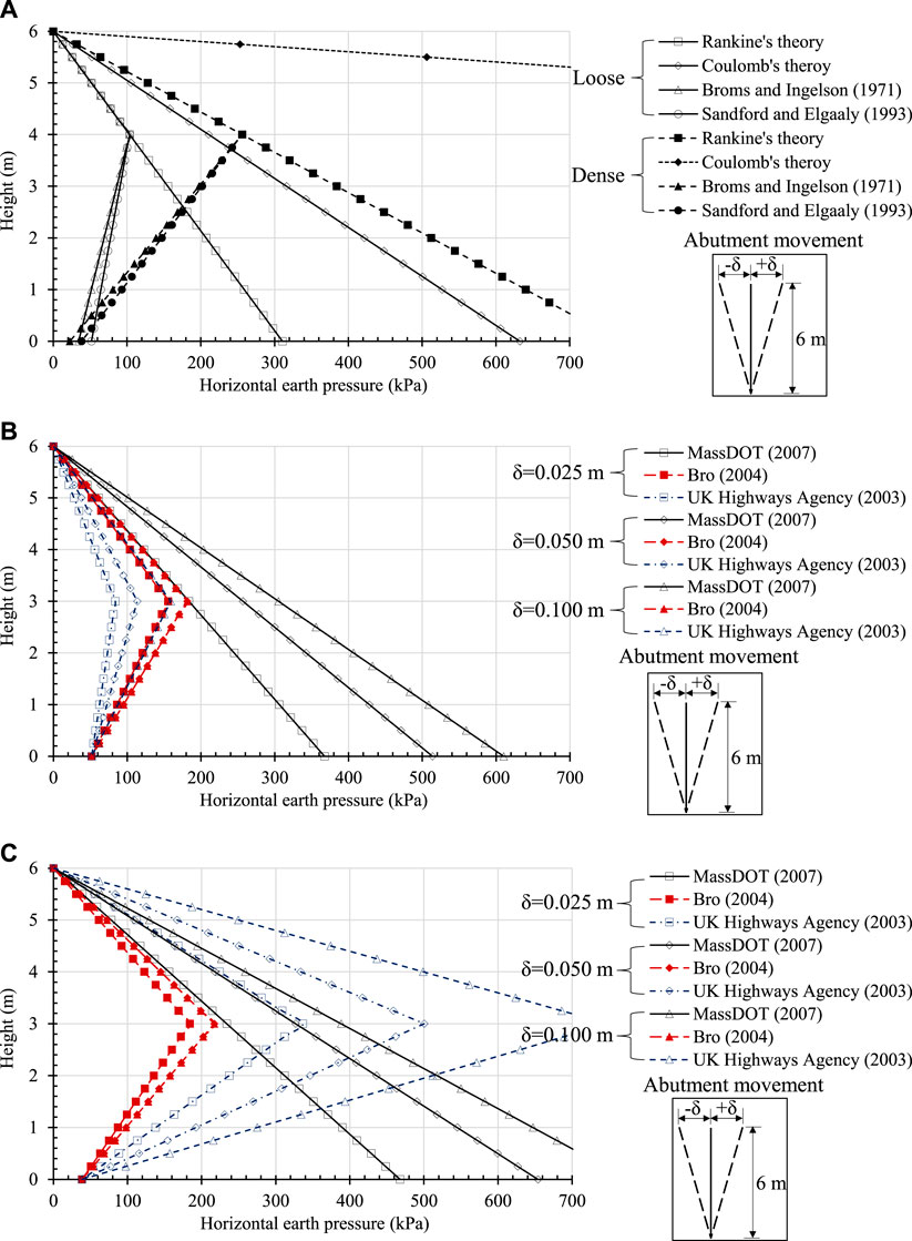
FIGURE 3. Horizontal earth pressures behind the abutment predicted for the loose and dense backfills based on: (A) the methods independent of the abutment movement, (B) the methods dependent on the abutment movement for the loose backfill, and (C) the methods dependent on the abutment movement for the dense backfill.
Huntley and Valsangkar (2013) observed that the horizontal earth pressures behind the abutment predicted by the methods of Rankine (1857), Coulomb (1776), Caquot and Kerisel (1948), Broms and Ingelson (1971), and England and Tsang (2005) did not agree well with the measured pressures behind the abutment. The horizontal earth pressures in the middle or within the lower portion of the backfill were lower than those predicted, while the horizontal earth pressures within the upper portion of the backfill might be higher than those predicted, likely due to the compaction-related effect. Behind an abutment, horizontal earth pressures may increase after several expansion-contraction due to temperature changes. This phenomenon is referred to as earth pressure ratcheting. Huntley and Valsangkar (2013) found that the horizontal earth pressures behind the abutment increased over 3 years and reached up to or even exceeded Rankine’s passive earth pressures at times. However, they did not attribute this observation to earth pressure ratcheting because such a phenomenon could also be caused by water accumulation in the backfill. In addition, they pointed out that the rotational movement was considered as the primary movement mode for the abutment when the horizontal earth pressure ratcheting was observed. However, in addition to Huntley and Valsangkar (2013), Kong et al. (2015) and Lawver et al. (2000) observed that translation was the primary abutment movement mode for some IABs. Kong et al. (2015) found the horizontal earth pressures behind the abutment decreased at the same movement in the second and third years as compared with those pressures in the first year, and they attributed this phenomenon to the soil disturbance and softening when it was pushed against by the abutment in the first year. Earth pressure ratcheting was not observed behind the abutment by Civjan et al. (2013) either.
Pile response
Ooi et al. (2010) found that the axial loads in drilled shafts estimated from strain gauges were much higher than expected after the placement of bridge planks. They attributed the differences to: 1) the difference between actual and estimated axial stiffness of drilled shafts, 2) the down-drag forces, 3) the creep of drilled shafts, and 4) the uneven distribution of the loads among drilled shafts. In addition, the axial loads in the shafts fluctuated seasonally and daily with temperatures (i.e., the axial loads were higher at night and in winter, but lower at daytime and in summer). Lawver et al. (2000) suggested that the redistribution of dead loads onto the piles due to the non-uniform solar-radiation-induced deformations across the bridge width might be one reason for this fluctuation. Ooi et al. (2010) attributed the observed seasonal fluctuations of axial loads partly to higher stream levels in winter and lower stream levels in summer, thus, reducing and increasing side frictions along the shafts, respectively. Huntley and Valsangkar (2014) pointed out that soil-structure interaction might also contribute to axial load fluctuations with temperatures in H-piles.
Figure 4 illustrates the forces applied onto the back of the abutment from the backfill and the possible pile moment profiles in summer and winter (θ is the interface friction angle between bridge abutment and backfill). In summer, the abutment moves toward the backfill, increasing the horizontal earth pressures behind the abutment, even up to the passive earth pressures. The upward movements of the backfill relative to the abutment apply uplift forces onto the abutment, thus reducing the axial load in the pile. However, the downward movements of the backfill relative to the abutment apply the down-drag forces onto the abutment, thus increasing the axial load in the piles in winter. As shown in Figure 4, one side of the H-pile closer to the backfill and near the abutment base is under compression while the opposite side is under tension when the bridge superstructure contracts. However, the closer side of the H-pile is under tension but the opposite side is under compression when the bridge superstructure expands (Huntley and Valsangkar, 2014). In addition, the H-pile is bent in a double curvature if the primary movement mode of the abutment due to temperature changes is translational. Given the orientation of the H-pile with the weak axis parallel to the bridge contraction and expansion direction, the bending moment in the strong axis can be induced by a thermal gradient along the bridge width, asymmetric loading on the bridge deck, and asymmetry of the superstructure.
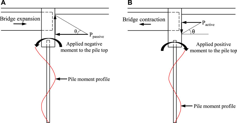
FIGURE 4. Pressures behind the abutment and induced pile moment profile: (A) in summer and (B) in winter (modified from Huntley and Valsangkar, 2014).
Because the air temperature varies daily and seasonally, the fatigue damage of the materials in IABs should be taken into account during bridge design. According to Razmi et al. (2013), the material may have two types of fatigue behavior: low-cycle behavior (i.e., the cyclic deformation is predominately inelastic) and high-cycle behavior (i.e., the cyclic deformation is predominately elastic). Because of the plastic deformation of H-piles in response to daily and seasonal temperature changes, the piles may have low-cycle fatigue behavior. Based on the numerical analysis, Razmi et al. (2013) found that the fatigue life of an IAB supported by H-piles decreased exponentially as the length of the bridge increased. They also found that the fatigue life of an IAB was predominated by the daily fatigue life, not the seasonal fatigue life because the daily temperature cycles had much larger frequency than the seasonal temperature cycles. By comparing the fatigue life from the finite element analysis (FEA) with that from the experiment, Abdollahnia et al. (2021) concluded that the FEA could accurately predict the fatigue life of H-piles in the experiment.
Skew effect on integral abutment bridges performance
In some projects, IABs are designed with a skew and designers must consider skew effects on the IAB performance. When the thermal movement of a bridge with a skew angle not exceeding ±10°C is within ±9.5 mm, this bridge can be designed without any special considerations about the skew effects (Greimann et al., 1982). For extremely skewed bridges (e.g., skew angle larger than ±40°), shear keys placed at the bottom of pile caps could prevent the transverse movement of the caps (Greimann et al., 1982). Expansion and contraction of a bridge superstructure may induce biaxial bending in steel H-piles if the H-piles are oriented with their strong axis being parallel or perpendicular to the abutment facing in a long skewed IAB. The horizontal earth pressures behind the abutment with a skew may not be uniform. Due to expansion of the bridge superstructure at a high temperature, the obtuse side of the abutment in a skewed IAB moved more toward the backfill than the acute side, inducing higher horizontal earth pressures on the obtuse side than those on the acute side (Elgaaly et al., 1992; Sandford and Elgaaly, 1993). However, the horizontal earth pressures on the obtuse and acute sides were similar when the bridge superstructure contracted at low temperatures (Sandford and Elgaaly, 1993). Figure 5 illustrates the behavior of skewed IABs at high temperatures. At high temperatures, the expansion of the bridge superstructure pushes the west abutment and the east abutment toward their backfill. In addition to the pressures applied perpendicularly onto the back of the west abutment (the resultant force of the pressures is Pn-w), the backfill applies the shear stresses along its back (the resultant shear force Pτ-w in the northeast direction) because of the tendency of the abutment to move in the southwest direction. Similarly, the backfill applies the normal pressures onto the back of the east abutment (the resultant force of the pressures is Pn-e) and the shear stresses along its back (the resultant shear force Pτ-e in the southwest direction). Therefore, the total force and moment induced by the interaction between the abutment and the backfill can be calculated by Eqs. 9–11:
In the above equations, Fn and Fτ are the total forces in the direction perpendicular to the back of the abutment and in the direction along the abutment facing, respectively;
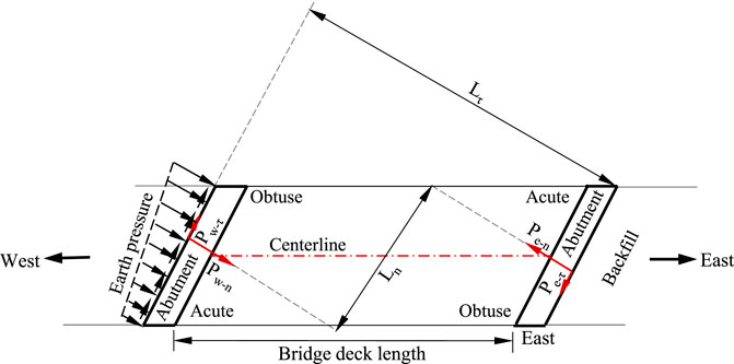
FIGURE 5. Forces applied to abutments from the backfill at high temperatures (modified from Jessee and Rollins, 2013).
Measures to mitigate temperature change-induced problems
Civjan et al. (2013) observed that the denser backfill resulted in higher horizontal earth pressures behind the abutment, more abutment rotation, but less pile movements. The loose backfill reduced the horizontal earth pressures behind the abutment; however, the backfill surface settlements induced by cyclic abutment movements due to daily and seasonal temperature changes increased progressively. To mitigate the temperature change-induced problems for IABs, rubberized soils, geocell-reinforced backfill, geogrid-reinforced backfill, waste tire bales (compressed and compacted packages of used tires), or EPS (expanded polystyrene) blocks have been used to replace typical backfill (aggregates), reduce horizontal earth pressures behind the abutment as the abutment moves toward the backfill, and reduce seasonal temperature change-induced backfill surface settlements (Horvath, 2000; Cui and Mitoulis, 2015; Zadehmohamad and Bazaz, 2017; Duda and Siwowski, 2020). Waste tire bales and EPS blocks are considered as lightweight backfill materials due to their low unit weights, which lead to lower horizontal earth pressures behind abutments. In addition, a compressible inclusion (e.g., EPS foam, tire shred, or tire-derived aggregates) has been placed between the abutment and the backfill to reduce the horizontal earth pressures behind the abutment and the pile moment (Hoppe, 2005; Caristo et al., 2018; Duda and Siwowski, 2020; Liu et al., 2021a; Zadehmohamad et al., 2021). Arsoy (2000) indicated that flexible piles were beneficial to prevent damages of pile-abutment connections. Construction joints between the bridge superstructure and the abutment reduced the moments of the supporting piles (Kim and Laman, 2012). Fang et al. (1994) and Arsoy (2000) found that the translational movement of the abutment toward the backfill resulted in higher horizontal earth pressures behind the abutment than the rotational movement of the abutment toward the backfill.
Liu et al. (2021a) and Liu et al. (2022a) conducted four physical model tests to investigate the effects of footing rigidity and abutment top movement magnitude on the horizontal earth pressures behind the abutment and the backfill surface settlements induced by seasonal temperature changes. In these tests, the abutment could rotate freely at the base of the abutment and the abutment base movement depended on the footing rigidity. According to the test results, the backfill surface settlements near the abutment increased as the footing rigidity and the abutment movement magnitude increased. In addition, the horizontal earth pressures behind the abutment approached the constant pressures after some seasonal temperature change cycles for all four tests. Furthermore, the force required to push the abutment toward the backfill decreased but the abutment base outward movement from the backfill increased as the footing rigidity decreased. Figure 6 shows two measures using the EPS geofoam and wrap-around geosynthetics to reduce backfill surface settlements induced by seasonal temperature changes for IABs. Liu et al. (2021b) observed that the EPS foam reduced the outward movement of the abutment base away from the backfill induced by seasonal temperature changes, and the thicker EPS foam with a lower density placed behind the abutment had more mitigation effects on the seasonal temperature change-induced problems (i.e., high horizontal earth pressures behind the abutment and large backfill surface settlements) for IABs. In addition, the wrap-around geosynthetics can significantly reduce the backfill surface settlements induced by seasonal temperature changes but increase the maximum horizontal earth pressures behind the abutment as the abutment moved toward the backfill. Therefore, a thick EPS foam combined with wrap-around geosynthetics is a promising measure to reduce horizontal earth pressures and backfill surface settlements behind the abutment induced by seasonal temperature changes. To mitigate the effect of the differential settlement at the interface between the abutment and the backfill, an approach slab is typically used to smooth the transition between the backfill and the bridge abutment. Typically, one end of the approach slab is seated on or connected with the bridge abutment, while the other end is supported on a sleeper slab with the adjacent pavement. As the settlement of the backfill near the abutment increases, more traffic loads on the approach slab are transferred onto the sleeper slab due to the formation of a void between the backfill surface and the approach slab, thus increasing the settlement at the end of the approach slab on the sleeper slab. Because the bridge abutment supported by a pile foundation or shallow foundation has little settlement, the differential settlement between the two ends of the approach slab results in a gradient change. Figure 7 shows the use of geosynthetics to reinforce the soil under the sleeper slab to mitigate backfill surface settlements induced by traffic loading and seasonal temperature change-induced abutment movements. Through the physical model tests, Liu et al. (2022b) found that geosynthetics under the sleeper slab could reduce the gradient change of the approach slab and the differential settlement of the two ends of the sleeper slab. So far, most of the mitigation measures for temperature change-induced problems have been studied by small-scale physical model tests; therefore, future studies and verifications through real projects are necessary.
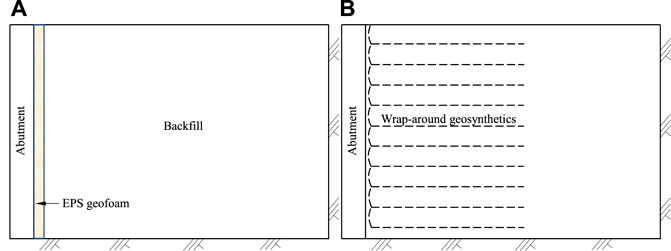
FIGURE 6. Measures to mitigate seasonal temperature change-induced problems: (A) compressible inclusion and (B) wrap-around geosynthetics.
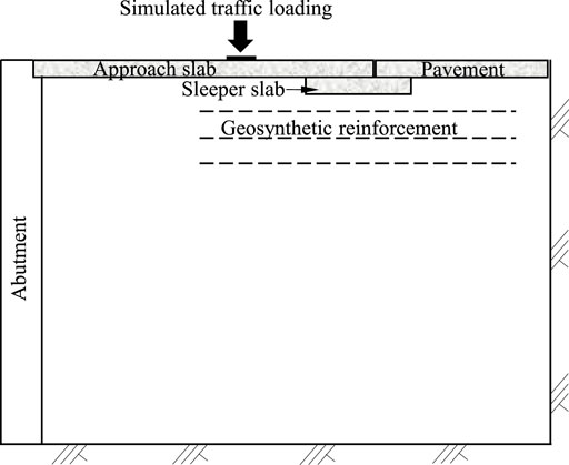
FIGURE 7. Measures to mitigate sleeper slab and backfill surface settlement induced by seasonal temperature change-induced abutment movements and traffic loading.
Conclusion
This paper summarizes the state of knowledge in integral abutment bridges (IABs) including the behavior of IABs due to seasonal temperature changes and presents the recent advances in the measures to mitigate temperature change-induced problems for IABs. Based on this study, the following conclusions can be made:
1) The length of frame abutment bridges should not be too long and over-lengthening of the bridge and large restraint from the backfill may over-stress the bridge superstructure at high temperatures.
2) Air temperature cannot directly represent the temperature in the entire bridge superstructure due to the presence of planar and vertical temperature gradients in the bridge superstructure. An effective bridge temperature (EBT) based on an air temperature should be used to predict the maximum bridge length change.
3) Abutment movement modes depend on abutment type, bridge length, and abutment height. For frame bridge abutments, the expansion and contraction of the bridge have little effect at the base of the abutment. For tall H-pile-supported abutments, the rotation of the abutment is the primary movement mode due to temperature changes.
4) Fluctuations of pile axial loads with temperature changes may be caused by the redistribution of dead loads in the continuous frame structure due to temperature gradients. The forces applied onto the back of the abutment by the backfill may change with the temperature (i.e., uplift forces at high temperature and down-drag forces at low temperature). The bending moment at the top of H-piles and perpendicular to the traffic moving direction may vary with the temperature.
5) Mode and magnitude of abutment movements can affect the magnitude and distribution of horizontal earth pressures behind the abutment. Earth pressure ratcheting was observed in some experimental studies but rarely occurred in the field, likely due to the difference of the primary abutment movement mode between the abutment in the field and the simulated abutment in the laboratory.
6) The skew effect on IAB behavior should be taken into account during the bridge design. Likely, the obtuse side of the abutment in a skewed bridge moves more toward the backfill than the acute side at high temperatures. As a result, the horizontal earth pressures on the obtuse side are larger than those on the acute side. Over years, the skew effect on the horizontal earth pressure difference between the obtuse side and the acute side diminishes, likely due to more permanent compression of the backfill on the obtuse side than that on the acute side.
7) The horizontal earth pressures behind the abutment increase as the relative density of the backfill and the abutment movement toward the backfill increase. Horizontal earth pressures behind the abutment predicted by the methods of Rankine (1857), Coulomb (1776), Broms and Ingelson (1971), and Sandford and Elgaaly (1993) are not appropriate, because these methods do not consider the factor of abutment movement magnitude on the horizontal earth pressures behind the abutment. In addition, the predicted horizontal earth pressures behind the bottom of the abutment by Massachusetts Department of Transportation (MassDOT) (2007) were much larger than those predicted by the design methods adopted in Sweden and United Kingdom.
8) Measures have been used in the field to prevent abutments and piles from failure, such as the use of a pressure relief system behind the abutment, a joint connection between the bridge superstructure and the abutment, a flexible connection between the bridge abutment and the piles, and a compressible material (e.g., loose sand and aggregate) placed around H-piles. In addition, geosynthetic-reinforced backfill and lightweight backfill (e.g., EPS blocks and waste tire bales) have been used to replace typical aggregate backfill and reduce the horizontal earth pressures behind the abutment and the temperature-change induced backfill surface settlements. However, the mitigation benefits of these measures need to be further verified through field tests before their applications in real projects.
Author contributions
HL did the literature review and prepared the draft of this paper. JH and RLP reviewed and revised the draft.
Funding
The article processing charges related to the publication of this article were supported by The University of Kansas (KU) One University Open Access Author Fund sponsored jointly by the KU Provost, KU Vice Chancellor for Research & Graduate Studies, and KUMC Vice Chancellor for Research and managed jointly by the Libraries at the Medical Center and KU—Lawrence.
Conflict of interest
The authors declare that the research was conducted in the absence of any commercial or financial relationships that could be construed as a potential conflict of interest.
Publisher’s note
All claims expressed in this article are solely those of the authors and do not necessarily represent those of their affiliated organizations, or those of the publisher, the editors and the reviewers. Any product that may be evaluated in this article, or claim that may be made by its manufacturer, is not guaranteed or endorsed by the publisher.
References
AASHTO (2014). AASHTO LRFD bridge design specifications. 7th ed. Washington, DC: American Associations of State Highway and Transportation Officials.
Abdollahnia, H., Elizei, M. H., and Kashyzadeh, K. R. (2021). Low-cycle fatigue behavior of H-shaped steel piles of an integral concrete bridge subjected to temperature variations. Mater. Today Proc. 46 (4), 1657–1662. doi:10.1016/j.matpr.2020.07.261
Abendroth, R. E., Greimann, L. F., and LaViolette, M. D. (2007). An integral abutment bridge with precast concrete piles (TRL report 438). IA, U.S: Center for Transportation Research and Education, and Iowa State University.
Arsoy, S. (2000). Experimental and analytical investigations of piles and abutments of integral bridges. PhD Dissertation. Blacksburg, VA: Virginia Polytechnic Institute and State University.
Arsoy, S. (2008). Proposed mathematical model for daily and seasonal thermal bridge displacements. Transp. Res. Rec. 2050 (1), 3–12. doi:10.3141/2050-01
British Highways Agency (2003). The design of integral bridges. BA, B. 42/96, ISBN 0115517227. London: Highways Agency (Now Highways England).
Barker, K. J., and Carder, D. R. (2001). Performance of an integral bridge over the M1-A1 link road at bramham crossroads (TRL report 521). London, U.K: Transportation Research Laboratory.
Barker, R. M., Duncan, J. M., Rojiani, K. B., Ooi, P. S. K., Tan, C. K., and Kim, S. G. (1991). Manuals for the design of bridge foundations (NCHRP report 343). Washington, DC, U.S: Transportation Research Board.
Breña, S. F., Bonczar, C. H., Civjan, S. A., DeJong, J. T., and Crovo, D. S. (2007). Evaluation of seasonal and yearly behavior of an integral abutment bridge. J. Bridge Eng. 1212 (3), 2963. doi:10.1061/(ASCE)1084-0702
Bro, A. T. B. (2004). Swedish road administration, Vägverkets allmänna tekniska beskrivning för broar (Swedish Standard Specifications for Bridges). Borlänge: Swedish Road Administration.
Broms, B. B., and Ingelson, I. (1971). Earth pressure against the abutments of a rigid frame bridge. Géotechnique 21 (1), 15–28. doi:10.1680/geot.1971.21.1.15
Caquot, A., and Kerisel, J. (1948). Tables for the calculation of passive pressure, active pressure, and bearing capacity of foundations. Paris: Gauthier-Villars.
Caristo, A., Barnes, J., and Mitoulis, S. A. (2018). Numerical modelling of integral abutment bridges under seasonal thermal cycles. Proc. Institution Civ. Eng. - Bridge Eng. 171 (3), 179–190. doi:10.1680/jbren.17.00025
Civjan, S. A., Bonczar, C., Breña, S. F., DeJong, J., and Crovo, D. (2007). Integral abutment bridge behavior: Parametric analysis of a Massachusetts bridge. J. Bridge Eng. 12 (1), 64–71. doi:10.1061/(asce)1084-0702(2007)12:1(64)
Civjan, S. A., Breña, S. F., Butler, D. A., and Crovo, D. S. (2004). Field monitoring of integral abutment bridge in Massachusetts. Transp. Res. Rec. 1892 (1), 160–169. doi:10.3141/1892-17
Civjan, S. A., Kalayci, E., Quinn, B. H., Breña, S. F., and Allen, C. A. (2013). Observed integral abutment bridge substructure response. Eng. Struct. 56, 1177–1191. doi:10.1016/j.engstruct.2013.06.029
Coulomb, C. A. (1776). “Essai sur une application des règles de maximis et minimis a` quelques problèmes de statique, relatifs a` l'architecture,” in Mémoires de mathématique et de physique présentés a` l'Académie royale des sciences par divers savants, et lus sans ses assemblées (Paris: De l'Imprimerie Royale), 7, 343–382.
Cui, L., and Mitoulis, S. (2015). “DEM analysis of green rubberized backfills towards future smart integral abutment bridges (IABs),” in Geomechanics from micro to macro (ISBN 9780429226854), IS-Cambridge, September 1–3, 2014 (CRC Press), 583–588.
Darley, P., and Alderman, G. (1995). Measurement of thermal cyclic movements on two portal frame bridges on the M1 (TRL report 165). London. U.K: Transportation Research Laboratory.
Darley, P., Carder, D. R., and Barker, K. J. (1998). Seasonal thermal effects over three years on the shallow abutment of an integral bridge in glasgow (TRL report 344). London, U.K: Transportation Research Laboratory.
DeJong, J. T., Howey, D. S., Civjan, S. A., Brena, S. F., Butler, D. S., Crovo, D. S., et al. (2004). “Influence of daily and annual thermal variations on integral abutment bridge performance,” in Geotechnical Engineering for Transportation Projects (ISBN 9780784407448), GeoTrans 2004, Los Angeles, CA, July 27–31, 2004 (ASCE), 496–505. doi:10.1061/40744(154)35
Deng, Y., Phares, B. M., Greimann, L., Shryack, G. L., and Hoffman, J. J. (2015). Behavior of curved and skewed bridges with integral abutments. J. Constr. Steel Res. 109, 115–136. doi:10.1016/j.jcsr.2015.03.003
Duda, A., and Siwowski, T. (2020). Pressure evaluation of bridge abutment backfill made of waste tyre bales and shreds: Experimental and numerical study. Transp. Geotech. 24, 100366. doi:10.1016/j.trgeo.2020.100366
Elgaaly, M., Sandford, T. C., and Colby, C. (1992). Testing an integral steel frame bridge. Transp. Res. Rec. 1371, 75–82.
England, G. L., and Tsang, N. C. M. (2005). Design of soil loading for integral bridges. Indian Concr. J. 79 (9), 53–59.
Fang, Y. S., Chen, T. J., and Wu, B. F. (1994). Passive Earth pressures with various wall movements. J. Geotech. Engrg. 120 (8), 1307–1323. doi:10.1061/(asce)0733-9410(1994)120:8(1307)
Frosch, R. J., Chovichien, V., Durbin, K., and Fedroff, D. (2006). Jointless and smoother bridges: Behavior and design of piles. Publication FHWA/IN/JTRP-2004/24. Joint Transportation Research Program. West Lafayette, IN: Indiana Department of Transportation and Purdue University. doi:10.5703/1288284313379
Girton, D. D., Hawkinson, T. R., and Greimann, L. F. (1991). Validation of design recommendations for integral‐abutment piles. J. Struct. Eng. 117 (7), 2117–2134. doi:10.1061/(asce)0733-9445(1991)117:7(2117)
Greimann, L. F., Yang, P. S., and Wolde-Tinsae, A. M. (1982). Skewed bridges with integral abutments. Transp. Res. Rec. 403, 64–72.
Greimann, L., and Wolde-Tinsae, A. M. (1998). Design model for piles in jointless bridges. J. Struct. Eng. 114 (6), 1354–1371. doi:10.1061/(ASCE)0733-9445(1988)114:6(1354)
Hallmarkl, R. (2006). Low-cycle fatigue of steel piles in integral abutment bridges. Master’s thesis. Norrbotten County: Dept. of Civil and Environmental Engineering, Div. of Structural Engineering, Luleå Univ. of Technology.
Hassiotis, S., Khodair, Y., and Wallace, L. F. (2005). “Full-scale testing of integral abutment bridge,” in Proceedings of the Transportation Research Board 84th Annual Meeting, Baltimore, MD, March 16–18, 2005 (Washington, DC: Federal Highway Administration). Integral Abutment and Jointless Bridges (IAJB), 199–210.
Hoppe, E. J. (2005). Field study of integral backwall with elastic inclusion (Report No. FHWA/VTRC 05-R28). VA. U.S.: Virginia Transportation Research Council.
Horvath, J. S. (2000). Integral-abutment bridges: Problems and innovative solutions using EPS geofoam and other geosynthetics (report No. CE/GE-00-2). New York, NY: Manhattan College.
Huffaker, C. D. (2013). Behavior and analysis of an integral abutment bridge. MS thesis. Logan: Utah State University.
Huntley, S. A. (2009). Field performance and evaluation of an integral abutment bridge. PhD dissertation. New Brunswick: The University of New Brunswick.
Huntley, S. A., and Valsangkar, A. J. (2014). Behaviour of H-piles supporting an integral abutment bridge. Can. Geotech. J. 51 (7), 713–734. doi:10.1139/cgj-2013-0254@cgj-ec.2015.01.issue-3
Huntley, S. A., and Valsangkar, A. J. (2013). Field monitoring of earth pressures on integral bridge abutments. Can. Geotech. J. 50 (8), 841–857. doi:10.1139/cgj-2012-0440
Jessee, S., and Rollins, K. (2013). “Passive pressure on skewed bridge abutments,” in Proceedings of the 18th International Conference on Soil Mechanics and Geotechnical Engineering, Paris, September 2–6, 2013 (Paris: Presses des Ponts, DL 2013, cop. 2013), 2019–2022.
Jorgenson, J. L. (1983). Behavior of abutment piles in an integral abutment in response to bridge movements. Transp. Res. Rec. 903, 72–79.
Kalayci, E., Civjan, S. A., and Breña, S. F. (2012). Parametric study on the thermal response of curved integral abutment bridges. Eng. Struct. 43, 129–138. doi:10.1016/j.engstruct.2012.05.007
Kamel, M. R., Benak, J. V., Tadros, M. K., and Jamshidi, M. (1996). Prestressed concrete piles in jointless bridges. PCI J. 41 (2), 57–67. doi:10.15554/pcij.03011996.56.67
Kim, W., and Laman, J. A. (2012). Seven-year field monitoring of four integral abutment bridges. J. Perform. Constr. Facil. 26 (1), 54–64. doi:10.1061/(ASCE)CF.1943-5509.0000250
Kirupakaran, K., Hanlon, B., Muraleetharan, K. K., and Miller, G. A. (2012). “Field-measured response of an integral abutment bridge,” in Geo congress 2012: State of the art and practice in geotechnical engineering, Oakland, CA, March 25–29, 2012 (ASCE), 2157–2166. doi:10.1061/9780784412121.221
Kong, B., Cai, C. S., and Kong, X. (2015). Field monitoring study of an integral abutment bridge supported by prestressed precast concrete piles on soft soils. Eng. Struct. 104, 18–31. doi:10.1016/j.engstruct.2015.09.004
Laaksonen, A. (2011). Structural behaviour of long concrete integral bridges. PhD dissertation. Tampere: Tampere University of Technology.
LaFave, J., Fahnestock, L., Brambila, G., Riddle, J., Jarrett, M., Svatora, J., et al. (2017). Integral abutment bridges under thermal loading: Field monitoring and analysis (Report NO. FHWA-ICT-17-017). IL, U.S: Illinois Center for Transportation.
Lan, C. (2012). On the performance of super-long integral abutment bridges: Parametric analyses and design optimization. PhD dissertation. Venice: University of Trento.
Lawver, A., French, C., and Shield, C. K. (2000). Field performance of integral abutment bridge. Transp. Res. Rec. 1740, 108–117. doi:10.3141/1740-14
Liu, H., Han, J., Jawad, S., and Parsons, R. L. (2022b). Effects of traffic loading on seasonal temperature change-induced problems for integral bridge approaches and mitigation with geosynthetic reinforcement. Int. J. Geomechanics 22 (6), 04022082. doi:10.1061/(ASCE)GM.1943-5622.0002393
Liu, H., Han, J., Jawad, S., and Parsons, R. L. (2021a). Experimental study on settlement of backfill in integral bridge abutments induced by seasonal temperature changes. Proceeding IFCEE 2021, 12–22. doi:10.1061/9780784483411.002
Liu, H., Han, J., Jawad, S., and Parsons, R. L. (2020). “Literature review of causes and mitigation techniques for bumps at ends of bridges,” in Proceeding at Geo-Congress 2020 (Minneapolis, MN: ASCE). doi:10.1061/9780784482810.089
Liu, H., Han, J., and Parsons, R. L. (2021b). Mitigation of seasonal temperature change-induced problems with integral bridge abutments using EPS foam and geogrid. Geotext. Geomembranes 49 (5), 1380–1392. doi:10.1016/j.geotexmem.2021.05.010
Liu, H., Han, J., and Parsons, R. L. (2022a). Settlement and horizontal Earth pressure behind model integral bridge abutment induced by simulated seasonal temperature change. J. geotechnical geoenvironmental Eng. 148 (6), 04022043. doi:10.1061/(ASCE)GT.1943-5606.0002812
Maruri, R. F., and Petro, S. H. (2005). “Integral abutments and jointless bridges (IAJB) 2004 survey summary,” in Proceeding of FHWA Conference on Integral Abutments and Jointless Bridges (IAJB), Baltimore, MD, March 16–18, 2005 (Washington, DC: Federal Highway Administration), 12–29.
Massachusetts Department of Transportation (MassDOT) (2007). Bridge Manual (2005 Edition). Boston, MA: Highway Division, Massachusetts Department of Transportation.
Ooi, P. S. K., Lin, X., and Hamada, H. S. (2010). Field behavior of an integral abutment bridge supported on drilled shafts. J. Bridge Eng. 15 (1), 4–18. doi:10.1061/(ASCE)BE.1943-5592.0000036
Pétursson, H., and Kerokoski, O. (2013). Monitoring and analysis of abutment-soil interaction of two integral bridges. J. Bridge Eng. 18 (1), 54–64. doi:10.1061/(ASCE)BE.1943-5592.0000314
Rankine, W. (1857). II. On the stability of loose Earth. Phil. Trans. R. Soc. 147, 9–27. doi:10.1098/rstl.1857.0003
Razmi, J., Ladani, L., and Aggour, M. S. (2013). Fatigue life of piles in integral-abutment bridges: Case study. J. Bridge Eng. 18 (10), 1105–1117. doi:10.1061/(ASCE)BE.1943-5592.0000434
Razmi, J., Ladani, L., and Aggour, S. M. (2014). Finite element simulation of pile behaviour under thermo-mechanical loading in integral abutment bridges. Struct. Infrastructure Eng. 10 (5), 643–653. doi:10.1080/15732479.2012.757794
Razmi, J., and McCabe, M. (2020). Analytical and computational modeling of integral abutment bridges foundation movement due to seasonal temperature variations. Int. J. Geomechanics 20 (3), 04019189. doi:10.1061/(ASCE)GM.1943-5622.0001622
Rowe, P. W. (1954). A stress-strain theory for cohesionless soil with applications to earth pressures at rest and moving walls. Géotechnique 4 (2), 70–88. doi:10.1680/geot.1954.4.2.70
Sandford, T. C., and Elgaaly, M. (1993). Skew effects on backfill pressures at frame bridge abutments. Transp. Res. Rec. 1415, 1–11.
Sherif, M. A., Ishibashi, I., and Lee, C. D. (1982). Earth pressures against rigid retaining walls. J. Geotech. Engrg. Div. 108 (5), 679–695. doi:10.1061/AJGEB6.0001288
Shoukry, S. N., William, G. W., and Riad, M. Y. (2006). “Structural behavior of an integral abutment bridge under environmental conditions,” in Proceeding of Structures Congress: Structural Engineering and Public Safety, St. Louis, MO, May 18–21, 2006 (American Society of Civil Engineers (ASCE)), 1–5. doi:10.1061/40889(201)158
Sigdel, L. D., Al-Qarawi, A., Leo, C. J., Liyanapathirana, S., and Hu, P. (2021). Geotechnical design practices and soil–structure interaction effects of an integral bridge system: A review. Appl. Sci. 11 (15), 7131. doi:10.3390/app11157131
Tatsuoka, F., Hirakawa, D., Nojiri, M., Aizawa, H., Nishikiori, H., Soma, R., et al. (2009). A new type of integral bridge comprising geosynthetic-reinforced soil walls. Geosynth. Int. 16 (4), 301–326. doi:10.1680/gein.2009.16.4.301
Terzaghi, K. A. (1936). A fundamental fallacy in earth pressure calculations. J. Boston Soc. Civ. Eng. 23 (2), 71–88.
Weakley, K. (2005). “VDOT integral bridge design guidelines,” in Integral abutment and jointless bridges (IAJB 2005), Baltimore, MD. (Federal Highway Administration and West Virginia Department of Transportation), March 16–18, 2005 (Washington, DC: Federal Highway Administration), 61–70.
White, H., Hans, P., and Peter, C. (2010). Integral abutment bridges: The European way. Pract. Periodical Struct. Des. Constr. 15 (3), 201–208. doi:10.1061/(ASCE)SC.1943-5576.0000053
Wolde-Tinsae, A. M., and Klinger, J. E. (1987). Integral abutment bridge design and construction. Maryland, U.S: State Highway Administration. (Report NO. FHWA/MD-87-04).
Zadehmohamad, M., and Bazaz, J. B. (2017). Cyclic behaviour of geocell-reinforced backfill behind integral bridge abutment. Int. J. Geotechnical Eng. 13, 438–450. doi:10.1080/19386362.2017.1364882
Keywords: abutment, bridge, earth pressure, mitigation, movement, pile, temperature
Citation: Liu H, Han J and Parsons RL (2022) Integral bridge abutments in response to seasonal temperature changes: State of knowledge and recent advances. Front. Built Environ. 8:916782. doi: 10.3389/fbuil.2022.916782
Received: 10 April 2022; Accepted: 27 June 2022;
Published: 15 August 2022.
Edited by:
Domenico Lombardi, The University of Manchester, United KingdomReviewed by:
Samanthika Liyanapathirana, Western Sydney University, AustraliaJafar Razmi, Arizona State University, United States
Copyright © 2022 Liu, Han and Parsons. This is an open-access article distributed under the terms of the Creative Commons Attribution License (CC BY). The use, distribution or reproduction in other forums is permitted, provided the original author(s) and the copyright owner(s) are credited and that the original publication in this journal is cited, in accordance with accepted academic practice. No use, distribution or reproduction is permitted which does not comply with these terms.
*Correspondence: Jie Han, amllaGFuQGt1LmVkdQ==