 Irene Olivia Ubay-Anongphouth
 Marolo Alfaro
- 1Department of Civil Engineering, De La Salle University, Manila, Philippines
- 2Department of Civil Engineering, University of Manitoba, Winnipeg, MB, Canada
Aging earth fill dams that were constructed in the mid-1950’s are beginning to show signs of instability associated with time-dependent degradation of shear strength. The strength degradation can be attributed to fissures, leaching of cementation, and creep in highly plastic clays, among other issues. The time-dependent processes are being examined in an earth fill dam that experienced slope instability but did not result in a loss of water. This paper discusses research findings on the mechanisms of delayed slope instability of an earth fill dam. Identifying the operating mechanisms of instability is useful in developing sound and practical remedial measures. It is also a useful way of being more proactive on the part of engineers in assessing the stability of dams at other generating stations that may not satisfy modern dam safety standards.
Introduction
Earth fill dams are critical components of hydroelectric generating stations. It is crucial to preserve the stability and serviceability of these structures. Despite their long-term viability, some of these aging structures began to exhibit indicators of instability. Fissures in the overconsolidated clay may compromise the stability of these aging earth structures. Leaching of gypsum owing to seepage, which weakens the clay, is another possible failure mechanism that could develop over time. There is also a possibility of time-dependent deformation or creep of the extremely plastic clay that was normally utilized in these structures.
Numerous stiff clays occur in their fissured state within the core of the zoned earth structures. These fissures could emerge during construction, as embankment zones tend to create brittle layers between plastic layers, which could result in localized cracks during mass deformation. The connection of pre-existing fissures with additional cracks may result in the formation of a progressive failure surface (Vallejo 1987; Vallejo and Shettima 2019). Fissures form weaker planes with greater permeability, resulting in reduced mechanical qualities when compared to undisturbed intact clays (Cotecchia et al., 2007; Vitone and Cotecchia 2011). Fissures represent planes of weakness with lower shear strength along which sliding would tend to happen. They cause shear stress concentrations at their tips that can locally exceed the shear strength of the clay and lead to progressive failure. Progressive failure can reduce the average shear strength along the slip surface to a value between the post-peak and residual strengths (Stark and Eid 1997).
As time passes, seepage from the forebay may dissolve gypsum, a naturally occurring cementation found within clay. Nodular aggregations of gypsum are frequently seen in the Lake Agassiz clays in and around Manitoba, Canada. Baracos (1977) and Graham et al. (1983) drew attention to the likelihood of cementation by gypsum. The gypsum is believed to originate from saline groundwater or from rivers bringing gypsum-rich sediment into the lake from Cretaceous deposits in Manitoba. Depletion of gypsum (or calcium sulphate) can result in increased brittleness of clay due to strain softening occurring at a lower axial strain, as well as decreased soil shear strength. After highly cemented gypsum-rich specimens attained about 13% axial strain, the strain reduced such as the case of dikes at Seven Sisters hydroelectric generating station in Manitoba, Canada (Garinger et al., 2004; Man et al., 2011).
The time-dependent nature of soil characteristics is frequently overlooked, which can result in excessive deformation and eventual failure or collapse (Campanella and Vaid 1974). In comparison to sandy materials, clayey soils typically exhibit creep behavior when subjected to steady pressure or self-weight. Creep is amplified in soils with high clay content and high activity (Mitchel and Soga 2005). For many years, slow creep motions may occur before a last period of increased movement results in failure. Significant creep deformations may serve as an early signal of delayed failure in this instance (Skempton 1977; Tavenas and Leroueil 1981; Vallejo and Shettima 2017).
This paper discusses the operating mechanisms of an aging water-retaining earth structure that experienced sudden instability despite its very long service life. Through site exploration, laboratory testing, and numerical modeling, the collapse mechanisms that caused abrupt instability were identified. It was critical to ascertain what prompted the abrupt movement to devise corrective measures.
Site description
CB Block Dam is a water-retaining earth fill dam constructed in the 1950s. The location of the hydroelectric generating station is not identified here upon the request of its owner and operator. The cross section with finite element mesh and phreatic line is depicted in Figure 1 (colors represent different types of materials). It was built on the site of an old creek. Due to the lack of an impermeable natural clay layer, an upstream side compacted clay blanket was placed and connected to the inclined clay core to control seepage. The dam is roughly 10.7 m high from core to crest, with a crest width of 4.6 m and a length of 360.0 m, concaved in the upstream direction. Local clay was often described in geotechnical investigation reports as high plastic lacustrine clay that was crumbly and fissured in nature. There was no record about the source of the clay core and clay blanket. It is likely that these were taken from the nearby clay deposits.
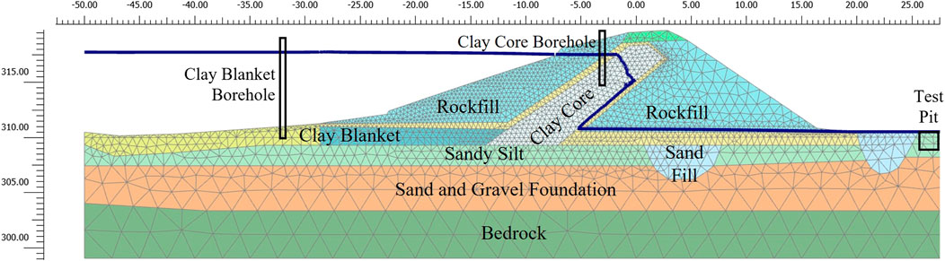
FIGURE 1. CB block dam cross section with approximate sampling borehole and test pit locations.
Despite remaining stable for almost 40 years over its operational life, the upstream slope of the aging dam experienced abrupt displacement. Although the sudden movement did not incur any water loss from the reservoir, it was a clear sign of instability. Though corrective measures were implemented to increase the stability of the investigated earth dam, it was still necessary to understand the cause of the instability. Given the similarity between the fissured clay from this site and the clay from the Seven Sisters generating station dikes, it was surmised that gypsum leaching due to seepage could also have driven the instability. Additionally, creep or time-dependent deformation was considered, as it could have been slowly occurring continuously during the service life of the earth dam.
Site exploration and soil sampling
Field investigation was conducted to gather site characterization information. For on-shore drilling, continuous soil sampling was performed on the clay core using 102 mm (4 in) Shelby tubes and a track-mounted Hollow Stem Auger (HSA). The bigger diameter Shelby tube was used rather than the standard 76.2 mm (3 in) tube to provide a more accurate portrayal of fissures in the soil samples gathered (Vallejo, 1989). Coring through riprap and rockfill was necessary to get undisturbed clay core samples. Sampling was limited to a specific depth within the clay core to avoid creating preferential flow routes for water through the clay core of the aging dam. All boreholes were sealed with cement-bentonite grout and then topped with bentonite chips. At locations further from the dam, test pits were excavated. These test pits can be used to observe fissures and significant gypsum inclusions in the soil layers, if any.
For off-shore drilling, undisturbed soil sampling occurred during the winter season, when the reservoir was sufficiently frozen to allow for the collection of clay blanket samples securely. A track-mounted drill rig equipped with a 76.2 mm piston tube sampler was used to collect samples of the clay blanket beneath the frozen reservoir. Shelby tubes with a smaller diameter than those used for onshore soil sample were employed since the clay blanket was anticipated to be less fissured. After drilling was done, boreholes were backfilled fully with bentonite grout or bentonite pellets and then sealed with bentonite chips and sand.
The clay was found to contain silt, very plastic, and fissured. Visual inspection of test pits revealed a greater concentration of silt than was observed in core or blanket locations. Additionally, nodules or streaks of gypsum were not detected during test pit excavations at any of the areas evaluated. Additional inspection by Shelby tube sample extrusions and laboratory tests was required to determine whether the clay had gypsum inclusions.
Laboratory testing
Index properties and deformation characteristics
Once extruded from Shelby tubes, collected samples were examined. Supplemental observations were made during the preparation of samples for laboratory tests. The clay core and blanket samples were found to be a mottled brown and grey mixture. Clay samples revealed a blocky and fissured texture with a medium to stiff consistency. It exhibited a high degree of plasticity, with silt inclusions observed during sample trimming. Extruded clay blanket samples resembled the clay core, but the upper layer (up to 0.6 m) was soft and brown in appearance. The samples were a mottled brown and grey mixture (greater than 0.6 m) with a medium consistency and a high degree of plasticity. Additionally, fissures and polished surfaces were observed, and clay fragments easily break away along fissure planes. When extruded and trimmed, no gypsum nodules were observed, which corroborated the findings during site investigations.
Clays in CB dam, regardless of their locations, were classified by the Unified Soil Classification System as “fat clay” with a high plasticity (CH). The index properties of CB clay are listed in Table 1.
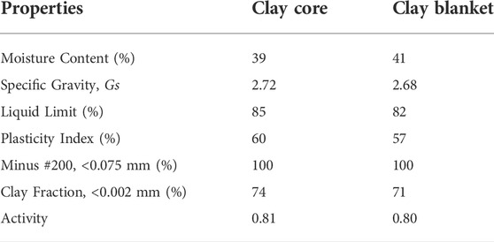
TABLE 1. Index properties.
One-dimensional consolidation tests were used to determine the deformation characteristics. The same test was used to determine creep in compression parameters, provided that the load application lasted long enough for secondary compression to occur. Table 2 summarizes the results of these tests. To ensure secondary compression (creep) developed, the maximum load was applied for 2 weeks, and displacement readings were taken daily during this observation period. The change in void ratio with logarithmic time was approximately linear during secondary compression, and the slope is defined as the coefficient of secondary compression or creep (Cα).
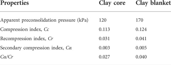
TABLE 2. Deformation characteristics.
The results indicate that the clay specimens were overconsolidated, with an overconsolidation ratio (OCR) of 2–6 for the clay core and 11–14 for the clay blanket. According to Widodo and Ibrahim (2012) and Ameratunga et al. (2016), the compression index values indicate that the samples were classified as stiff clay with slight compressibility. The range of Cα values corresponds to secondary compressibility of clays ranging from low to moderate. The Cα/Cc ratios are comparable to those observed in the field for overconsolidated clays tested by Ameratunga et al. (2016).
Mineralogy and particle orientation
To determine the shape, orientation, and possible presence of gypsum particles in clay particles, specimens were examined using a Scanning Electron Microscope (SEM) equipped with a backscattered electron and an Energy Dispersive X-ray (EDX) system. X-ray Diffraction (XRD) analysis was also used to determine the mineralogical composition of the clay and non-clay constituents, as it is a more conclusive test than EDX analysis. Additionally, the XRD results would indicate the presence or absence of gypsum in the soil.
SEM images of clay core specimens reveal a flocculated structure with slight particle alignment and the presence of micro fissures. Clay blanket specimens demonstrate that most particles form broad overlapping sheets. The observed non-clay particles, by means of EDX, were identified as quartz and dolomite.
XRD analyses of clay core and blanket specimens confirm the mineralogical composition. Clay minerals included interlayered smectite and illite, along with kaolinite and mica, as well as traces of attapulgite. Smectite was the dominant clay mineral, indicating that clays in CB dam were expansive. Additionally, the mineralogy of the clay specimens did not reveal the presence of gypsum. Non-clay minerals noted were quartz, feldspar, and dolomite, all of which are typically found in silt. These results corroborated the presence of silt and the absence of gypsum discovered during site investigations and sample extrusions. The absence of gypsum in all clay samples indicated that leaching was unlikely to have caused the delayed instability of the earth dam.
Strength characteristics
The strength parameters for the clay core and clay blanket were determined using isotropically consolidated undrained triaxial compression tests and consolidated undrained direct simple shear tests, respectively, based on the shape of the postulated slip surface.
Cross-shear strengths were determined using isotropically consolidated undrained triaxial compression (CIU) tests (ASTM D4767). The test specimens were prepared in accordance with the standard 2:1 height-to-diameter ratio and trimmed to a recommended diameter of 71.12 mm to account for the effect of soil fissures on soil strength.
Critical State Soil Mechanics framework was used to interpret the peak and post peak shear strength parameters. Post peak shear strengths were determined using end-of-test values ranging from 14 to 16 percent axial strain. Results are shown in Figures 2–4. As illustrated in Figure 2, when clay core samples are sheared at a mean effective stress of 100–200 kPa, they exhibit isotropic elastic behavior (mΔp ≈ Δu). The samples sheared at 400 kPa were normally consolidated, whereas the remaining samples were over-consolidated. Strain softening was generally observed in the stress-strain curves that resulted (Figure 3).
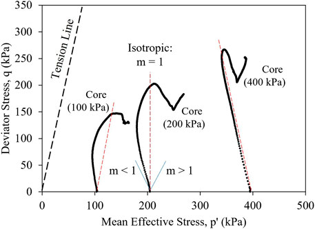
FIGURE 2. Stress paths in p’-q space from CIU triaxial tests on CB clay core samples.
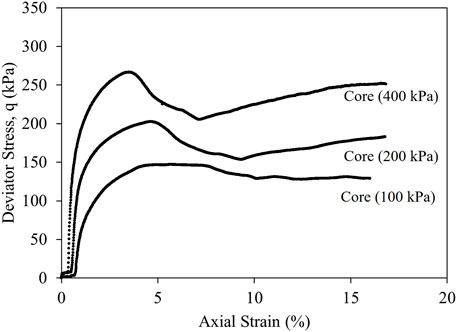
FIGURE 3. Stress-strain behavior from CIU triaxial tests on CB clay core samples.
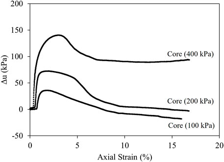
FIGURE 4. Porewater pressure measurements from CIU triaxial tests on CB clay core samples.
The shear strength of clay blanket samples along the horizontal plane was determined using consolidated undrained (CU) direct simple shear tests (ASTM D6528). Figures 5–7 illustrate the results of these tests.
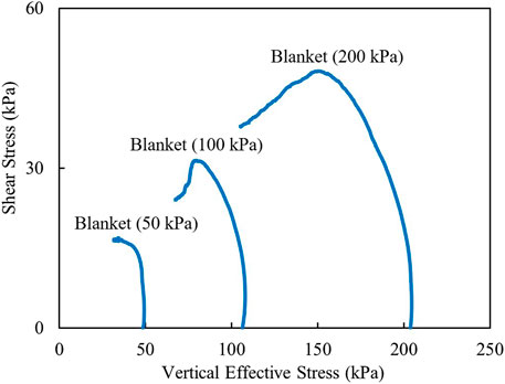
FIGURE 5. Shear stress versus vertical effective stress plot from CU direct simple shear tests on CB clay blanket samples.
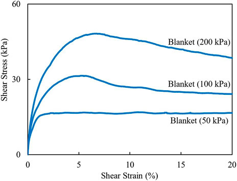
FIGURE 6. Stress-strain behavior from CU direct simple shear tests on CB clay blanket samples.
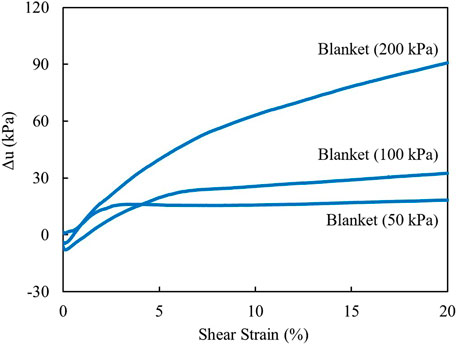
FIGURE 7. Porewater pressure measurements from CU direct simple shear tests on CB clay blanket samples.
Consolidated drained (CD) direct shear tests (ASTM D3080) were used to determine the residual strengths of both the clay core and clay blanket. The multiple reversal method was used to repeatedly shear clay samples until 100 percent strain was reached, corresponding to approximately 63 mm of displacement, provided that sufficient clay sample remained within the direct shear box. The normalized stress-strain behavior of the clay core and blanket samples, respectively, is depicted in Figures 8, 9. They indicate that the specimens underwent strain softening. As samples were continuously strained, it was observed that shear strength decreased after reaching peak strength. It was also notable that the degree of softening decreased as applied vertical stress increased. As Bishop et al. (1965) discussed, this behavior was considered typical for fissured overconsolidated clays. As confining stress increases, the stress-strain curve gradually transitions from brittle to ductile behavior.
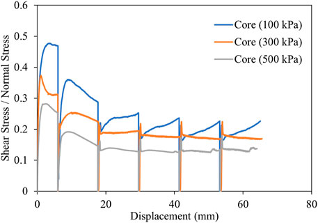
FIGURE 8. Normalized stress-displacement behavior of CB clay core samples from direct shear tests.
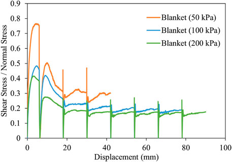
FIGURE 9. Normalized stress-displacement behavior of CB clay blanket samples from direct shear tests.
Table 3 summarizes the effective shear strength parameters obtained from strength tests conducted on clay core and clay blanket samples. Post peak shear strengths were determined using end-of-test values ranging from 14 to 16 percent axial strain. Additionally, the peak and post-peak shear strengths obtained from direct simple shear tests were indicated. Post peak strengths were determined at the conclusion of direct simple shear tests performed at approximately 20% strain. Rivard and Lu (1978) recommended that post-peak strength values assume zero cohesion for fissured clays.
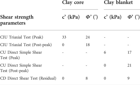
TABLE 3. Effective shear strength parameters.
Numerical modeling
The high clay content of the core and blanket may have adversely affected the effect of creep under sustained constant pressure during the service years of the aging structure, as the dam geometry has remained relatively unchanged since it was completed in the 1950s. Very slow creep movement could have occurred for many years prior to the accelerated movement (Tavenas and Leroueil 1981). As a result, time-dependent creep deformation analysis must be incorporated into the model.
PLAXIS 2D, a finite element geotechnical engineering software capable of performing sequential deformation and stability analyses, was used for numerical modeling. PLAXIS 2D was chosen as the modeling platform because its Soft Soil Creep (SSC) model enables the incorporation of time-dependent creep behavior into the deformation analysis. The SSC model was developed by deriving a differential form from the logarithmic creep law associated with secondary consolidation. It was then extended towards general three-dimensional states of stress and strain by incorporating Modified Cam-Clay and viscoplasticity, with a Mohr-Coulomb failure criteria (Vermeer and Neher, 1999). SSC is an extension of the pre-existing Soft Soil (SS) model by including a modified creep index (µ*) parameter in addition to the modified compression (λ*) and modified swelling (κ*) indices. The SSC parameters used in the numerical modelling are shown in Table 4.
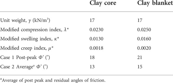
TABLE 4. Numerical modelling parameters.
Two cases were considered, as indicated also in Table 4, in terms of shear strength parameters. In Case 1, post peak or critical state strengths were used because it was assumed that the compacted clay blanket had reached its fully softened state after being submerged for over fifty years. Additionally, it was believed that the clay core has strain softened by the presence of silt lenses and its fissured structure. Strain softening until residual shear strength was also observed in the results of the consolidated drained direct shear tests. In Case 2, the average of the post peak and residual shear strengths was used, considering that only a portion of the clay core and blanket had yielded. This corresponds to the case where certain elements in the model developed residual strength along the slip surface during displacement, as Stark and Eid (1997) reported. With relatively large movement or strain, the strength is reduced from the post peak value to the average of the post peak and residual strengths. As a result, creep was incorporated into Case 2 using the SSC model. Case 1 incorporated the SS model.
The numerical modeling geometry was created using construction drawings and other documentation provided by the dam owner and operator. The finite element mesh was generated after fully defining the dam geometry. PLAXIS 2D uses a robust triangulation procedure to generate triangular elements with 15 nodes. The finite element mesh is shown in Figure 1, refined to achieve model convergence. Vertical and horizontal movement were constrained at the base in terms of boundary conditions. The boundary conditions along the horizontal ends are fixed in the x-direction but are unbounded in the y-direction. At the bottom boundary, groundwater flow was constrained. On the upstream side of the earth dam, hydraulic conditions were set based on the operational head pond level. A steady-state analysis was used to determine the phreatic surface (seen in Figure 1) within the dam. For both the clay core and the clay blanket, hydraulic conductivity values of 8.464 × 10⁻¹¹ m/s were used. Hydraulic conductivity was determined following ASTM D5048. In PLAXIS 2D, the staged construction mode was used to define the construction stages. After initial stress generation, consolidation calculation was conducted per construction phase. Consolidation considered pore water dissipation over a specified period and included the effect of changes to the active geometry of the dam. Additional consolidation phases were needed to observe the deformation behaviour of the earth dam at time interval after the end of construction and impounding.
A safety calculation would establish the safety factor in relation to stability. The stresses, deformations, and pore water pressures were determined using the finite element method. They are then used in a stability analysis to determine the dam’s factor of safety using the strength reduction approach. PLAXIS 2D calculated the factor of safety using the phi-cohesion (φ′-c’) reduction technique. The shear strength parameters were gradually reduced until a fully developed failure mechanism was obtained in the final step. In addition to displacement results, the incremental displacements generated during the safety calculation phase could be used to verify the probable failure surface (PLAXIS, 2018).
The numerical model must be capable of representing the observed and documented conditions over the service life of the earth dam. Even after forty years in service, movement was still observed until the sudden movement in the upstream section after more than fifty years. While the unexplained movement did not result in the complete collapse of the structure, it is viewed as a sign of instability. These parameters must be reflected in the dam’s calibrated model.
Figure 10 illustrates the progression of deformation in the dam without creep. When creep was not considered, displacements remained constant forty years after impoundment was completed. At 50 years, the factor of safety using Case 1 was 1.36. Because investigations indicated movement in the dam even after 40 years of service and instability at 50 years, the model based on Case 1 was unable to reproduce observed dam conditions.

FIGURE 10. Deformation development using Case 1 without creep at different stages after impounding.
Figure 11 demonstrates the creep analysis results for Case 2, demonstrating that the model continued to move even after fifty years, replicating what has been observed throughout the dam service life. As can also be noted from the figure, there is prevalent movement at the upstream side with respect to time. Knowing that the dam already showed signs of instability, a factor of safety less than unity was anticipated. Using Case 2, a factor of safety of 0.99 was obtained when creep was included in the model. This implied that the final calibrated numerical model based on observed dam conditions should include time-dependent creep deformation analysis using clay strengths between the post-peak and residual shear strengths. As previously stated, the average of the fully softened and residual shear strengths would be reached only upon achieving sufficient shear displacement. Creep was used to achieve this level of shear displacement.
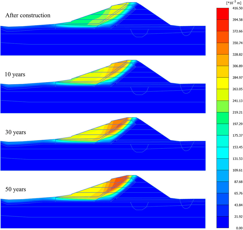
FIGURE 11. Deformation development using Case 2 with creep at different stages after impounding.
Investigation results
It was initially thought that since the fissured high plastic CB clay was similar to the clay at Seven Sisters generating station, it was probable that the sudden instability could also be due to the leaching of gypsum caused by seepage. However, site exploration and laboratory tests verified that gypsum was no-existent in the clay. This prompted into considering time-dependent deformation or creep in the analysis.
The results of the model calibration provided insight into the cause of the delayed dam instability. The dam has remained under constant load for over forty years due to the absence of changes such as dam heightening and significant changes in reservoir level. Creep movement occurred due to the high clay content and plasticity of the clay core and blanket under the constant load of the dam. Creeping occurred over time in the upstream section because of the compacted blanket being tied into the inclined clay core. The absence of naturally occurring clay on the downstream side resulted in the predominant upstream movement, as seen in Figure 11. Over the years of service, sufficient movement or straining occurred because of creep. The sufficient straining with respect to time justifies the use of a reduced clay shear strength value in stiff fissured clay, ranging from post peak to an average of post peak and residual shear strengths. The predominant creep movement along the upstream slope and the progressive deterioration of the shear strength of the fissured overconsolidated clays resulted in the delayed dam instability.
The dam owner and operator used the findings of this study to aid in the planning and repair of the investigated earth dam. Additionally, similar aging water-retaining earth fill dams were evaluated using the calibrated time-rate-dependent constitutive soil model, which included shear strength degradation due to creep strains.
The finite element geotechnical engineering software used in the numerical modeling is capable of performing sequential deformation and stability analyses. It is recognized that a fully coupled time-rate-dependent constitutive soil model, including strength degradation due to creep strains would improve the long-term stability analysis of clay slopes in earth fill dams. A study is on-going to develop a numerical model that simulates accumulative creep shear strains causing steady shear strength degradation resulting to delayed slope instability.
Conclusion
Water-retaining dams and dikes are expected to have a long service life, and their instability would have adverse consequences.
The assessment of the aging earth dam demonstrated the critical nature of considering long-term analysis of structures when considering creep. Because creep analysis parameters can be obtained from oedometer tests, which are routinely performed on field samples, time-dependent creep can be easily integrated into the design and/or investigation process. The use of a finite element method in combined with a time-dependent soil creep model would result in predicted time-dependent movements or instabilities from the long-term analysis. Using results from this analysis, instrumentation can be planned in such a way that these dams are effectively monitored for instability. This demonstrates the importance of more frequent long-term in-situ monitoring, as well as a proper remedial plan in the event that one is required.
Data availability statement
The original contributions presented in the study are included in the article/supplementary material, further inquiries can be directed to the corresponding author.
Author contributions
Conception or design of the work: IU-A, MA. Experimental program: IU-A, MA. Model generation and results: IU-A. Analysis of results and interpretation: IU-A, MA. Drafting the article: IU-A, MA. Critical revision of the article: IU-A, MA. Final approval of the version to be published: MA.
Funding
The authors would like to acknowledge the financial and technical support from Ontario Power Generation, the owner and operator of the hydroelectric generating station.
Acknowledgments
The Structural Engineering Department and Geological Science Department of the University of Manitoba contributed their services and testing equipment to the research. The authors also thank Mr. Alitking Anongphouth, Mr. Aron Piamsalee, Mr. Brian Wazney, Dr. David Kurz, and Mr. Kerry Lynch of the Geotechnical Engineering Research Group for their kind assistance and technical support in the site investigation, soil sampling, and laboratory testing.
Conflict of interest
Maple Leaf Drilling Ltd. provided their drilling services and expertise during site investigation and sampling.
The authors declare that the research was conducted in the absence of any commercial or financial relationships that could be construed as a potential conflict of interest.
Publisher’s note
All claims expressed in this article are solely those of the authors and do not necessarily represent those of their affiliated organizations, or those of the publisher, the editors and the reviewers. Any product that may be evaluated in this article, or claim that may be made by its manufacturer, is not guaranteed or endorsed by the publisher.
References
Ameratunga, J., Sivakugan, N., and Das, B. M. (2016). Correlations of soil and rock properties in geotechnical engineering. New Delhi, India: Springer India.
American Society for Testing and Materials (2010). Annual book of ASTM standards. Philadelphia, PA, USA.
Baracos, A. (1977). Compositional and structural anisotropy of Winnipeg soils - a study based on scanning electron microscopy and X-ray diffraction analyses. Can. Geotech. J. 14 (1), 125–137. doi:10.1139/t77-009
Bishop, A. W., Webb, D. L., and Lewin, P. I. (1965). Undisturbed samples of london clay from the ashford common shaft: Strength–effective stress relationships. Géotechnique 15 (1), 1–31. doi:10.1680/geot.1965.15.1.1
Campanella, R. G., and Vaid, Y. P. (1974). Triaxial and plane strain creep rupture of an undisturbed clay. Can. Geotech. J. 11 (1), 1–10. doi:10.1139/t74-001
Cotecchia, F., Vitone, C., Cafaro, F., and Santaloia, F. (2007). “The mechanical behaviour of intensely fissured high plasticity clays from Daunia,” in Proceedings of the second international workshop on characterisation and engineering properties of natural soils, 1975–2001.
Garinger, B., Alfaro, M., Graham, J., Dubois, D., and Man, A. (2004). Instability of dykes at seven Sisters generating station. Can. Geotech. J. 41 (5), 959–971. doi:10.1139/t04-037
Graham, J., Noonan, M. L., and Lew, K. V. (1983). Yield states and stress–strain relationships in a natural plastic clay. Can. Geotech. J. 20 (3), 502–516. doi:10.1139/t83-058
Man, A., Graham, J., and Blatz, J. (2011). Seepage, leaching, and embankment instability. Can. Geotech. J. 48 (3), 473–492. doi:10.1139/t10-083
Rivard, P. J., and Lu, Y. (1978). Shear strength of soft fissured clays. Can. Geotech. J. 15 (3), 382–390. doi:10.1139/t78-035
Skempton, A. W. (1977). “Slope stability of cuttings in Brown london clay,” in 9th international conference in soil Mechanics (Tokyo, Japan, 261–270.
Stark, T., and Eid, H. (1997). Slope stability analyses in stiff fissured clays. J. Geotech. Geoenviron. Eng. 123 (4), 335–343. doi:10.1061/(asce)1090-0241(1997)123:4(335)
Tavenas, F., and Leroueil, S. (1981). Creep and failure of slopes in clays. Can. Geotech. J. 18, 106–120. doi:10.1139/t81-010
Vallejo, L. E. (1987). The influence of fissures in a stiff clay subjected to direct shear. Géotechnique 37 (1), 69–82. doi:10.1680/geot.1987.37.1.69
Vallejo, L. E. (1989). Fissure parameters in stiff clays under compression. J. Geotech. Engrg. 115 (9), 1303–1317. doi:10.1061/(asce)0733-9410(1989)115:9(1303)
Vallejo, L. E., and Shettima, M. (2017)., 2017. Orlando, Florida, 372–381.An explanation for the delayed failures of natural slopes and Earth damsGeotech. Front.
Vallejo, L. E., and Shettima, M. (2019). “Fatigue crack propagation in stiff clays forming part of earth dams and natural slopes,” in Eighth international conference on case histories in geotechnical engineering (Philadelphia, Pennsylvania, 610–617.
Vermeer, P. A., and Neher, H. P. (1999). “A soft soil model that accounts for creep,” in Beyond 2000 in computational geotechnics (Amsterdam, The Netherlands, 249–261.
Vitone, C., and Cotecchia, F. (2011). The influence of intense fissuring on the mechanical behaviour of clays. Géotechnique 61 (12), 1003–1018. doi:10.1680/geot.9.p.005
Keywords: earth fill dam, slope stability, plastic clay, creep, laboratory tests, numerical modelling
Citation: Ubay-Anongphouth IO and Alfaro M (2022) Delayed instabilities of water-retaining earth structures. Front. Built Environ. 8:927137. doi: 10.3389/fbuil.2022.927137
Received: 23 April 2022; Accepted: 19 July 2022;
Published: 29 August 2022.
Edited by:
Jie Han, University of Kansas, United StatesReviewed by:
Irini Djeran-Maigre, INSA Lyon France, FranceCheng Lin, University of Victoria, Canada
Mounir Bouassida, Tunis El Manar University, Tunisia
Copyright © 2022 Ubay-Anongphouth and Alfaro. This is an open-access article distributed under the terms of the Creative Commons Attribution License (CC BY). The use, distribution or reproduction in other forums is permitted, provided the original author(s) and the copyright owner(s) are credited and that the original publication in this journal is cited, in accordance with accepted academic practice. No use, distribution or reproduction is permitted which does not comply with these terms.
*Correspondence: Marolo Alfaro, TWFyb2xvLkFsZmFyb0B1bWFuaXRvYmEuY2E=