 Roberto Riquelme
 Ricardo Herrera
- Department of Civil Engineering, University of Chile, Santiago, Chile
Few seismic design codes for industrial structures exist worldwide. Among them, the Chilean design code was put to the test by the Maule earthquake of 2010, one of the largest seismic events in recent years. Although the seismic performance of industrial steel structures designed under these provisions was satisfactory, the standard was revised based on the accumulated evidence on the performance after the event and the advances in seismic design since the code was released in 2003. The revision process led to a number of modifications to the provisions, including those for structures based on concentrically braced frames (CBFs), a structural typology widely used in the industry. The modifications, mainly aimed at improving seismic performance in severe events, ranged from the seismic demand to the provisions for sizing structural elements and connections. This work evaluates the effect of these modifications on the design and seismic performance of CBFs. For this purpose, six industrial steel structures were designed using the current standard and the proposed version. The performance was evaluated through static non-linear analyses in 3D models according to the methodology prescribed by the FEMA P695 standard. The models included the non-linearity of braces, columns, beams or struts, and anchor bolts. The results showed similar performance between the structures designed using the proposed and the current version of the standard, in terms of overstrength and response modification factors. However, the performance improved when comparing the maximum drift that the structures can reach and the energy levels they are able to accumulate at these drifts. In terms of the cost–performance ratio, the improvement in performance is associated with moderate increases in cost.
1 Introduction
The standard NCh2369.Of2003 “Seismic design of industrial structures and facilities” (INN, 2003) is one of the few codes worldwide dedicated to the seismic design of buildings and industrial facilities. It was born from the need of a small engineering community in a country with limited resources where large industrial projects, mainly copper mining and cellulose, were under development. The NCh2369 standard, which became official in 2003, reflects the state of the art of the seismic design of Chilean and international industrial installations since foreign standards, particularly those of the United States, constituted a natural and usually complementary reference to the Chilean standard.
Over the years, the NCh2369 standard has shown that the designs developed under its requirements present adequate performance, in accordance with its design philosophy, which is continuity of operation. Notwithstanding, the Maule 2010 and Coquimbo 2015 earthquakes provided a wealth of evidence on the performance of industrial structures, which led to a review and update of the standard. The modifications covered various aspects such as seismic demand, design of steel structures, design of concrete structures, and design of special structures.
In Chile, concentrically braced frame (CBF) structures are a widely used typology, particularly in large buildings and structures to support heavy mining equipment, such as screeners, hydrocyclone batteries, feeders, belts, filters, hoppers, and silos. The structural typology just described is affected by modifications to the seismic demand and CBF design requirements.
Although the seismic events mentioned previously have provided information on the performance of industrial structures, the large number of theoretical investigations about the performance of earthquake-resistant systems based on braced frames available in the literature is focused on residential or office buildings. Since industrial buildings are generally non-building structures, they have greater irregularities in the distribution of mass and stiffness than building structures, both in plan and elevation. Thus, this work provides new information on the performance assessment of non-building structures.
Within the literature, there are a limited number of studies about the seismic performance of industrial steel structures (building and non-building structures) designed according to the provisions of NCh2369. In this context, Astica (2012) studied the performance of a primary crusher operation building, by means of non-linear static (pushover) and dynamic (time-history) analyses using OpenSees software and found that the design of the structure provided it with high strength and limited ductility, evidenced by the absence of inelastic deformations under seismic stresses induced by seismic records.
Chavez (2012) studied the seismic behavior of column-based anchorages on a moment frame and a braced frame modeling the support as semi-rigid, using the OpenSees software, based on the proposal of Astica (2012). In this proposal, the non-linearity of anchor bolts was incorporated. For column bases, the one proposed by Takamatsu et al. (2005) was used. This work shows the importance of considering support flexibility in structural models to obtain a better representation of the real behavior of the structure.
Urzúa and Herrera (2017) designed and analyzed two typical structures of the mining industry, according to the requirements of the current NCh2369 standard (INN, 2003) and the provisions of the AISC 360–341 standard (AISC, 2005a). This research evaluated the impact on the seismic performance of the use of one or the other standard, characterized through performance parameters and the methodology prescribed by the FEMA P695 standard (FEMAP695, 2009). The models were developed in the SAP2000 structural analysis software and considered phenomenological elements calibrated with the test results observed by Black et al. (1980). According to the results, the proposed non-linear phenomenological brace model adequately reproduces the hysteretic behavior observed in the reference tests, if the dominant failure mode is not a low-cycle fatigue fracture. Regarding the anchorages, an energy dissipation effect that reduces the demand on the resisting elements is observed. This research also shows that the structure based on inverted V-bracing is 30% heavier when it is designed using the North American AISC (2005a) practice. The increase of weight lies in the chevron frame beams, which are designed to resist the expected and residual capacities of the braces. This finding is interesting because it provides a first approximation to one of the modifications to NCh2369 analyzed here.
Herrera and Zúñiga (2019) evaluated the effect of the proposed modifications to the NCh2369 standard in its version before being released for public comments, specifically the modifications related to CBFs. The performance evaluation was carried out according to the methodology defined in the FEMA P695 standard in SAP2000 using the same phenomenological formulation used by Urzúa and Herrera (2017). The study revealed that while the structure is more flexible, the effect of the flexible anchorage tends to the behavior of the rigid anchorage, as the number of floors increases.
Finally, Rodriguez (2020) focused on the evaluation of the seismic performance of two industrial structures, composed of multi-tiered braced frames of different heights, designed for the proposed version of NCh2369 and AISC standard requirements (AISC, 2010a; AISC, 2010b). The models of Rodriguez (2020) were developed in the OpenSees software, using fiber beam elements with discretized fiber sections to include spread of plasticity along the columns, beams, and braces. The models were validated with experimental data and with the results of the study by Imanpour et al. (2016b), which were based on Auger (2017).
Auger (2017) modeled the brace using three types of elements: a rigid zone at the joint of the brace to the column–beam node; the connection plate or gusset, modeled as an elastic element; and finally, the brace itself, which is included as inelastic elements, with the fiber-discretized cross-section. The Menegotto–Pinto material model is used, including initial imperfections to induce flexural buckling.
It is important to note that the models of Rodríguez (2020) do not include the non-linearity of the anchor, but if a model intends to comprehensively represent the behavior of CBFs, it should consider this particularity. Thus, the models developed in this work collect the developments of Chávez (2012), Urzúa and Herrera (2017), Herrera and Zúñiga (2019), and Rodríguez (2020).
Of all the previous works, only the research of Herrera and Zúñiga (2019) addresses some of the modifications related to CBF design, which are now included in the proposed version of the NCh2369 standard.
The studies described so far point out the most significant aspects of models that have been developed to assess the performance of different industrial structures in Chile. All these structures are based on CBFs, the performance of which is usually controlled by the bracing system, and their modeling is based on the proposal of Uriz et al. (2008) on brace buckling models, which has been used by other authors such as Wijesundra et al. (2014), Imanpour (2016a) or Auger (2017) to implement CBF models for different purposes.
The response of braces has been extensively studied experimentally (Black et al., 1980, among others) showing the importance of slenderness in global buckling, local slenderness in local buckling, and the effect of edge conditions and low-cycle fatigue on the behavior.
To represent the behavior of steel braces, there are three types of models: phenomenological, based on using simple non-linear functions calibrated to experimental results to reproduce the global axial force–elongation response of the brace; based on uniaxial beam–column elements; and based on finite element models (FEM). The models of the second type are used in this work, and they require the inclusion of initial stresses, initial geometric imperfections, changes in the shape of the cross-section under load, the representation of material properties, and the occurrence of local buckling.
For braces subjected to flexural buckling, the interaction between the second-order moment and axial force is relevant, and different approaches to the problem have been developed. Most of them are based on elastic beam–column elements, with inelasticity introduced through plastic hinges at mid-length; however, current approaches use inelastic beam–column elements including distributed plasticity (fiber-based model). Thus, in this context, it is usual to divide the brace member into several beam–column elements (multi-element model) with fiber discretization to capture the interaction between second-order moment and axial force.
Among the models based on beam–column elements, the formulation proposed by Uriz et al. (2008) is one of the most used by other authors because of its ability to accurately represent the buckling capacity, post-buckling behavior, tensile capacity, and hysteretic response of compact cross-sections.
The work of Uriz et al. (2008) highlights the sensibility of the response in the models to the maximum amplitude of the initial imperfection. Thus, initial imperfections larger than expected can trigger buckling prematurely. D'Aniello et al. (2013) highlight the importance of including initial imperfections to induce buckling, either through deformations of the system geometry (initial curvature) or through the element properties in the form of residual stress distribution.
Studies after Uriz et al. (2008) have considered different strain amplitudes and initial deformation under parabolic and sinusoidal distributions, where the effects of the gusset plate at the ends have been included. Among them, Wijseundra et al. (2014) investigated the capabilities and limitations of the buckling model proposed by Uriz et al. (2008) in the OpenSees software framework to reproduce the hysteretic response of braces with different boundary conditions at their ends. The connection plates are included at the ends as an inelastic beam–column-type element based on the force of length 2t g (where t g is the thickness of the connection or gusset plate) with fiber cross-section discretization to capture the complicated interaction between the bending moment and axial gusset force due to the change in the axial force of the brace.
2 Code modifications
The modifications to the official NCh2369 standard (INN, 2003) cover aspects ranging from seismic demand to the dimensioning of structures, of which the following are those affecting structures based on CBFs.
2.1 Seismic demand
The modifications related to seismic demand are as follows:
- The increase from three to four occupancy categories in the proposed version of the standard;
- The adoption of the soil classification from standard NCh433 (INN, 2012).
- Regarding horizontal seismic loading, the seismic coefficient and the response spectrum in the proposed version correspond to the same of the current version but multiplied by the S factor (Eq. 1), which is associated to the soil type (INN, 2020, Table 5.4).
- The plateau of the response spectrum or maximum seismic coefficient is no longer defined by a maximum coefficient (Tables 5–7, INN, 2003) that depends on the seismic zone, damping ratio, and response modification factor. It is defined by the following expression (Eq. 2).
where Ao = effective ground acceleration.
R = response modification factor
ξ = critical damping ratio.
S, T’,n = parameters dependent on the soil type.
I = importance factor, dependent on the occupation category.
T = vibration period for the first horizontal mode.
- In the proposed version of the standard, the three orthogonal components of the earthquake are always combined by means of directional combinations (way of combining the components of the seismic action), unlike the current version, where the plan orthogonal components are allowed to be used independently under certain conditions and where the vertical component is applied in well-defined cases. The current version combines the horizontal (Eh) and vertical (Ev) components as follows: E = Eh + Ev or E = Eh + 0.3Ev, and the proposed version combines the components Exz = 1.0Ex + 0.3Ey + 0.6Ez, Eyz = 0.3Ex + 1.0Ey + 0.6Ez, Ezx = 0.6Ex + 0.2Ey + 1.0Ez, and Ezy = 0.2Ex + 0.6Ey + 1.0Ez.
The change in these provisions recognizes the importance of vertical accelerations in the structural design of industrial buildings and that many industrial facilities in Chile have been designed omitting vertical accelerations.
In both versions of the standard, it is allowed to include the vertical component of the earthquake as a static vertical force given by a constant seismic coefficient, which is 2A o/3g for the current version (INN, 2003) and 1.18 S A o /g in the proposed version (INN, 2020). As an alternative to the static vertical seismic force, both versions allow performing a vertical dynamic analysis. The current version uses the horizontal design spectrum with R = 3 and ξ = 3%, while the modifications propose the spectrum of Eq. 3.
where T V = vibration period for the first vertical mode.
- The seismic deformations should be calculated using Eq. 4, and the elastic spectrums of reference defined in Eq. 5 and Eq. 6 for vertical and horizontal accelerations, respectively. The reference spectrum is defined at ξ = 5%. If a different damping ratio is required, a factor equal to (0.05/ξ)0.4 may be used to change the magnitude of the spectrum. The reference spectrum is based on past earthquake records, incorporating those obtained from 2010 onward.
where
d = seismic deformation
d o = deformation from gravitational loads
d d = deformation calculated using the spectrum of the reference.
T 0, p = parameters dependent of the soil type.
T H = vibration period for the horizontal mode.
The difference between the proposed requirements and the current version of the standard is in the term d d in Eq. 4. For the current version, d d is calculated as the elastic deformation obtained from elastic analysis with the design spectrum (Eq. 1), amplified by R 1 = R (Q o/Q min) to estimate the inelastic deformations, as the standard indicates. For the proposed version, d d is calculated as the deformation obtained from an analysis with the reference spectrum (Eq. 5).
Finally, the modifications introduced adopt the combinations established in NCh3171 (INN, 2010); thus, a single local standard defines the load combinations for structural design purposes. Thus, the load combinations for the current version consider a load factor of 1.1 for seismic loads (E), while the proposed version considers 1.4.
2.2 Steel CBF requirements
While many of the provisions of the current version are based on good practices and criteria that have led to the development of structures that have performed seismically well, the new version of the standard introduces changes to make it consistent with other normative references such as ANSI/AISC 341-10 (AISC, 2010a). Furthermore, the new version provides a more rational design methodology that is updated to the state of the art of the earthquake-resistant design of CBFs. Thus, the new standard introduces concepts such as expected capacity and residual capacity, as well as specific checks for CBFs similar to those contained in the AISC standard. The variations from the current code are detailed as follows.
To determine the required column resistance, an overstrength factor 0.7 R 1 > 1.0 is introduced to ensure that the braces behave inelastically, allowing the release of energy of the structure, and that the columns stay in the elastic range so that the overall stability of the structure is not compromised. In terms of the brace strength, the current version sets a maximum allowed level of axial compression forces of 80% of the nominal axial strength. This limit has been eliminated in the new version because even though it built in overstrength in the design, it led to a possible failure mechanism in the columns, rather than on the braces.
For X-braced, split-X-braced, V-braced, and inverted V-braced configuration, additional requirements are included for beams or struts. The required axial strength for beams or struts must be determined from the equilibrium between the expected brace strength in tension and the expected brace strength in compression or the residual post-buckling compressive brace strength.
While in the current version of NCh2369 the design of connections is made for the nominal strength of the element or a percentage of it (column splices are calculated for seismic loads amplified by 2), the proposed modifications introduce the concepts of expected and residual strength, which are defined in Eqs 7–11. According to the proposed version of NCh2369 (INN, 2020), the required connection strength must be calculated for a seismic load amplified by 0.7 R 1 ≥ 1.0. However, the required strength of the connected element does not need to be greater than the expected strength of the connected element nor greater than the maximum load that the system can transfer to the connection. Additionally, the required connection strength must not be less than half of the expected strength of the connected element.
where
T ye: expected tensile strength.
P ne: expected compressive strength.
P ner: residual post-buckling compressive strength.
M pe: expected flexural strength.
M pered: expected flexural strength reduced by axial load.
A g: gross section area of the element.
Z: cross-section plastic module.
R y: expected-to-nominal yield stress ratio.
F y: nominal yield stress.
F cre: critical buckling stress calculated with expected yielding stress.
P: maximum axial load from load combinations.
The column splice strength must be equal or greater than the lower expected strength of the connected elements.
For seismic struts and braces, the current version of NCh2369 (INN, 2003) requires connections to have a strength equal to 100% of the axial capacity of the member (not specify how that capacity is calculated). In the modified version, the connection must be designed to resist the expected axial tensile and compressive strength of the member. However, the required connection strength does not need to be larger than the value calculated with the seismic load amplified by 0.7 R 1 > 1.0 or the maximum load that the system can transmit. Additionally, the connection must be designed to sustain the flexural moment or rotation induced by the buckling of the member.
Anchor bolts subjected to tension shall have and anchor chair and the bolt shall be visible to allow for inspection and repair, and the thread shall have the sufficient length to enable retightening of the nuts. In the current version, this requirement can be avoided if the anchor bolts are designed for seismic loads amplified by 0.5R > 1.5, while for the proposed version, the seismic loads must be amplified by 0.7R > 1.0.
The braces in X-braced frames shall be connected at the point of intersection. In the current version, this point can be considered fixed in the direction perpendicular to the plane of the frame when one of the diagonal elements is continuous. In the proposed version, one diagonal must be in tension to take this consideration.
3 Methodology
Six industrial structures are designed according to the current and proposed versions of NCh2369, using linear elastic models, to obtain the weight of the structure and particularly of the seismic-resistant system (braced frames), forces in elements that are part of the seismic-resistant system, seismic deformations, design forces for the vertical bracing connections and struts, and design forces for the anchorages. These results are used to evaluate the effect of the modifications on the structural characteristics.
For all structures, the force and displacement demands for the earthquake horizontal components are obtained through a response spectrum analysis, while the vertical component is considered an equivalent force given by a seismic coefficient. Although the designs were evaluated with the vertical response spectrum, the application of an equivalent force has proven to be more conservative.
For each structure, two non-linear models are developed, one for the design according to the current requirements and the other for the proposed requirements. The models are developed and calibrated in SAP2000 software. These are based on the models developed in OpenSees by Rodriguez (2020), Wijesundra et al. (2014). The models in SAP2000 try to emulate the models developed in OpenSees and reproduce the good agreement that the latter have shown with the experimental data. In SAP2000, the uniaxial elements (frame-type) are linear-elastic and only allow the inclusion of inelastic behavior through plastic hinges. Thus, to emulate a distributed plasticity model such as that developed in OpenSees by other authors, the elements must be modeled considering multiple fiber hinges in their extension.
The non-linear SAP2000 models are subjected to non-linear static “Pushover” analysis according to FEMA P695 (2009), ATC40 (1996), and FEMA 440 (2005) methodologies to determine the following seismic performance parameters:
• Overstrength (Ω0)
• Ductility based on period (μ), from the capacity spectrum.
• Ductility reduction factor (R μ ), which is calculated in accordance with Newmark and Hall (1982).
With the results of the pushover analyses, an approximation of the modification factor for the structural response R (R = Ω 0 R μ ) is obtained based on the “structural response modification factor” standards [ATC-19 (ATC, 1995)].
A non-linear static (pushover) analysis is conducted in the models of the different structures under study. This analysis is performed for factored gravity loads (1.05 DL + 0.25 LL, with DL permanent loads and LL live loads) and a lateral distribution of forces proportional to the fundamental mode shape of the structure.
The performance assessment is developed using the reference spectrum defined in the standard (Eq. 5), which is based on past earthquake records.
The process is summarized in two flowcharts in Figure 1.
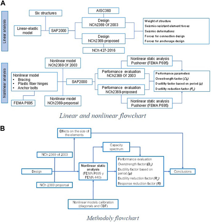
FIGURE 1. Research flowcharts: (A) Linear and nonlinear analysis flowchart; (B) Methodology flowchart.
4 Prototype structures
The models for the six industrial structures (Figure 2) designed for both the current and proposed requirements of the Chilean standard NCh2369 incorporate relevant non-linearities in braces, columns, beams (struts), brace connections, and anchor bolts.
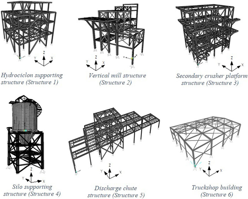
FIGURE 2. Analysis cases.
The first structure has four split-X and inverted V braced frames at perimeter frames, with four levels and regular mass and stiffness distribution. The second structure has six levels, X, split-X, and inverted V braced frames and has irregular stiffness distribution both in plan and in height. Furthermore, it has a high eccentricity of the center of gravity in plan and elevation. The third prototype is a four-story structure, braced in both main directions with X and inverted V braced frames. It has irregular mass and stiffness distribution mainly in plan. The fourth structure is a square in plan, with four X and split-X braced frames supporting a silo, so it has a significant mass concentrated on the top level. The fifth structure has three levels of platforms, and longitudinally it has X braced frames, while in the transverse direction, it is fixed to the cavern where the structure is located, and this structure has a regular distribution of stiffness and mass. The sixth and last structure is a truck shop building, which is made by moment frames connected by X braced systems; this structure presents a bridge crane near the roof, so it has a certain concentration of mass at this level.
The seismic parameters to define the seismic demand are as follows:
• Structure 1: zone 2, soil type II and B for the current and proposed version, respectively; importance factor 1.0; damping ratio 3%; and response modification factor, R = 3.
• Structure 2: zone 2, soil type III and C (or B) for current and proposed version, respectively; importance factor 1.2; damping ratio 3%; and response modification factor, R = 3.
• Structure 3: zone 2, soil type II and B for current and proposed version, respectively; importance factor 1.2; damping ratio 3%; and response modification factor, R = 3.
• Structure 4: zone 1, soil type II and B for current and proposed version, respectively; importance factor 1.2; damping ratio 3%; and response modification factor, R = 3.
• Structure 5: zone 2, soil type II and B for current and proposed version, respectively; importance factor 1.2; damping ratio 3%; and response modification factor, R = 3.
• Structure 6: zone 3, soil type II and B for current and proposed version, respectively; importance factor 1.0; damping ratio 2%; and response modification factor, R = 4.
Although six structures are analyzed, there are eight cases of analysis since two additional cases are studied for structure 2: one because the new soil classification divides the previous soil type III into soil types C and D; therefore, the structure must be studied for the two soil types; and the other is to study the advantage of using braces made of square hollow structural sections (HSS) or starred-angles (XL).
5 Modeling considerations
Based on what was proposed by Uriz et al. (2008) and the specifications of Imanpour et al. (2016b) and Auger (2017), Rodriguez (2020) developed a model for multi-tiered concentrically braced frames using OpenSees software. This model serves as the basis for the models developed in this work using SAP2000 software.
The model conceptualized by Auger (2017) described as follows presents essentially the same formulation as the model proposed by Imanpour et al. (2016b). Auger’s models comprised columns, braces, and struts of the braced panels plus a gravity column, used to include the P-Delta effects due to the gravity load on the rest of the structure not part of the braced frame. The gravity column is connected to the braced frame by rigid struts.
The model, although representing a planar frame, is a three-dimensional model as it incorporates the deformation and out-of-plane behavior of columns and braces. To capture the effects of geometric non-linearities and large displacements, the corotational formulation is used. The model considers initial imperfections on columns and braces, which are subdivided into shorter elements to impose an initial deformed geometry: 10 elements for the columns between struts and beams and eight elements for the braces. Columns are continuous over their full building height and hinged at the base, in-plane and out-of-plane, and are torsionally restrained at their ends. They are represented by force-based non-linear beam–column elements using the Menegotto–Pinto material model, as it simulates kinematic and isotropic hardening, as well as the Bauschinger effect.
The cross-section of the column is discretized into fibers. According to Agüero et al. (2006), a bar subdivided into at least eight elements with at least 16 fibers adequately predicts the buckling behavior.
The struts are represented as elastic elements since low deformations are expected in them, as these elements are designed for the forces that develop once the brace in compression buckles.
The braces are modeled using non-linear force-based beam–column elements to reproduce compression buckling and yielding in tension. The brace cross-section is discretized based on fibers without considering residual stresses, unlike the columns, and the Menegotto–Pinto material model is used considering the expected yield stress (RyFy). The yield strength is reduced by 5% (0.95 RyFy) in the critical (bottom) panel. At the ends of the braces, rigid elastic elements are used to represent the connection between braces, columns, and struts. As illustrated in Figure 3, when cross braces are used, one is continuous and the other is discontinuous, and each diagonal has rigid elements, one on each side of the joint.
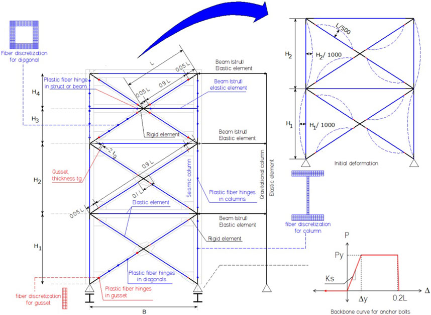
FIGURE 3. Concentrically braced frame (CBF) model.
The rigid elastic zones in the braces are used to simulate the in-plane stiffness of the gusset connection (Imanpour et al., 2016b). They are modeled with a length L r equal to 5% of the length of the continuous diagonal. Their properties are defined from the properties of the braces, with the equations (Eqs 12–23) described in Auger (2017).
where
A d, I xd , I yd , and J cd: diagonal cross-section properties
A cc, I xcc , I ycc , and J cc: column cross-section properties
A v, I xv , I yv , and J v: beam or strut cross-section properties
Ad.rigid, Ixd.rigid, Iyd.rigid, and Jd.rigid: column rigid elastic cross-section properties
A cc.rigid, I xcc.rigid , I ycc.rigid , and J cc.rigid: column rigid elastic cross-section properties
A v.rigid, I xv.rigid , I yv.rigid , and J v.rigid: beam rigid elastic cross-section properties
The rigid elastic elements are not only limited to the brace ends but also in the ends of beams (struts) and in the columns around the column-strut-brace node since all the elements around the node are affected in their stiffness by the connection. For columns, the rigid zone has a length of L v = L r sin(θ) and for beams or struts L h = L r cos(θ) (Tremblay, 2003).
The initial imperfection of the braces is sinusoidal, with a maximum amplitude of L/500 at the center of the braces, where L is the length of half a brace (continuous). The rigid portions are free of initial deformation. The imperfection is imposed out-of-plane of the frame in an S-shaped fashion.
The modeling of the brace connection to the beam–column node influences the behavior of the braces, and consequently the behavior of the structure during the non-linear analysis. The modeling adopted by Auger (2017) considers a spring to reproduce the out-of-plane bending stiffness and torsion of the connection plate (gusset) according to the information provided by Tremblay (2003), where rotation occurs when the brace is compressed. The modeling adopted by Auger (2017) developed in OpenSees was verified by comparison with that adopted by Imanpour (2015) developed using Abaqus software.
Wijesundra et al. (2014) used a different approach to that used by Rodriguez (2020) and proposed by Auger (2017). In Wijesundra et al. (2014), an elastic hinge between the rigid elastic element and the brace itself is not assumed but a plastic fiber hinge on the elastic element is imposed (element with width equal to the Whitmore width and thickness equal to the gusset thickness) that allows representing the plastic behavior. This formulation has the advantage of representing the physical phenomenon from the model and the constitutive law of the material and of being independent of assigning certain parameters based on experience, as in the case of torsional and bending stiffness outside the gusset plane.
The flexible portion of the gusset is included as a non-linear column–beam element of length 2 t g (t g gusset thickness) with fiber discretization whose dimensions are Whitmore’s width and gusset thickness.
To include the non-linear behavior of the anchorage, the anchorage is represented using two non-linear elements in parallel. The first one, corresponding to a non-linear Nlink multi-linear plastic element representing the anchor bolts, and the second one representing the concrete pier is a GAP element. The definition of the elements that represent the bolts requires the backbone curve of the bolts, which Urzúa and Herrera (2017) define from the yield stress and tensile strength of the steel material (Figure 3). The parameters of the force-deformation curve shown in Figure 3 are as follows:
P y = expected yield tension for bolts = F ye A s
F ye = expected yield stress = R y F y , F ye = 372 [MPa] for ASTM A36.
F y = nominal yield stress, F y = 248 [MPa] for ASTM A36.
R y = expected-to-nominal yield stress ratio.
A s = bolt cross-section area
E s = steel elasticity modulus = 200,000 [MPa]
K c = column axial stiffness.
K s = bolt axial stiffness = E s A s /L.
K p = concrete pier axial stiffness, K p = 10K c
L = exposed length of anchor bolts.
Δy = yield deformation, Δ y = P y/K s
5.1 Calibration of constitutive models
Since the material non-linearities are included through plastic fiber hinges, the Giuffrè–Menegotto–Pinto uniaxial model (Eq. 24) is used because it allows including the Bauschinger effect and the kinematic and isotropic hardening behavior (Imanpour et al., 2016c). The material model is calibrated with monotonic loading test results. The parameters resulting from the calibration are shown in Table 1 for the HSS (A50 steel) and XL (A270ES steel).
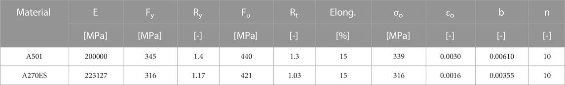
TABLE 1. Material model parameters.
Once the material model is calibrated, the brace models developed following the considerations of Uriz et al. (2008) and Wijesundra et al. (2014) are subjected to cyclic loads to calibrate different features (Figure 4). As the reference approaches have been developed in OpenSees and the models developed in this work are formulated in SAP2000, plastic fiber hinges distributed along the elements are used to emulate the distributed plasticity behavior available in OpenSees.
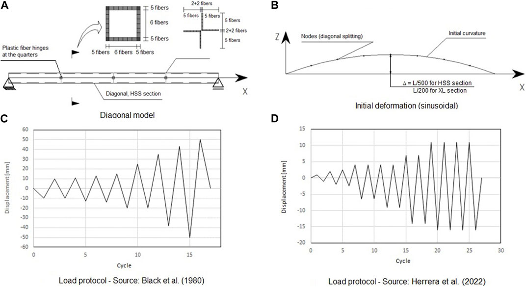
FIGURE 4. Non-linear brace model and loading history: (A) HSS Brace model; (B) Initial deformation; (C) Load Protocol (Black et al., 1980); (D) Load Protocol (Herrera et al., 2022).
The models are calibrated against the results of Black et al. (1980) for square sections and of Herrera et al. (2022) for XL sections. In the calibration process, the number of plastic fiber hinges and the initial imperfection amplitude are varied until an appropriate fit of the numerical response with the experimental response is achieved (Figure 5).
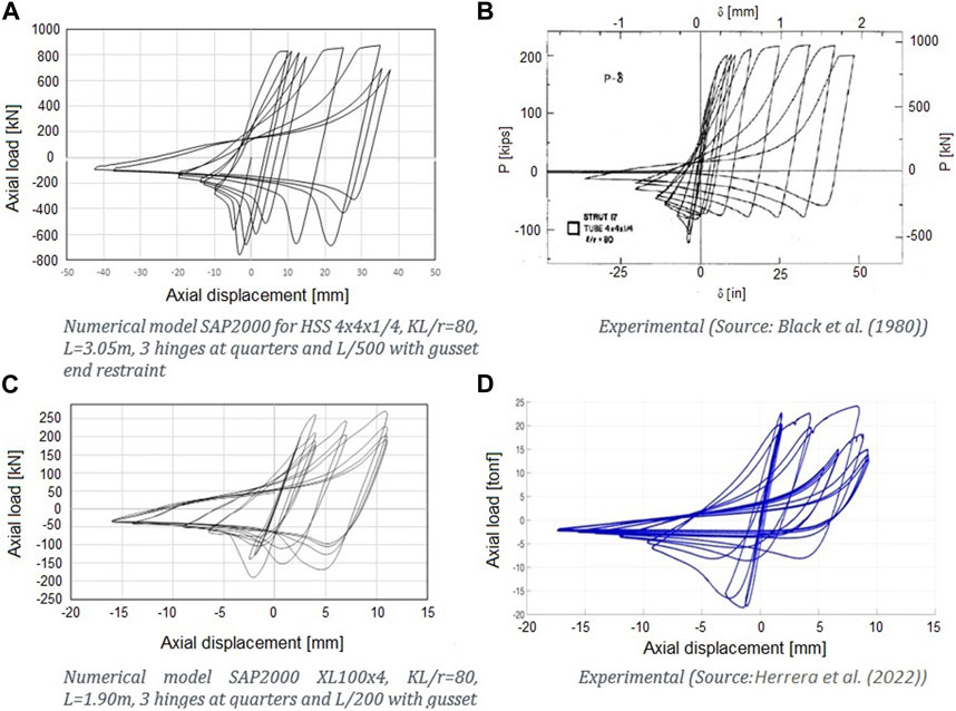
FIGURE 5. Hysteresis loop—numerical models vs. experimental data. (A) Numerical results for HSS 4x4x1/4 tested by Black et al. (1980); (B) Test data for HSS 4x4x1/4 tested by Black et al. (1980); (C): Numerical results for XL100x4 tested by Herrera et al. (2022); (D) Test data for XL100x4 tested by Herrera et al. (2022).
Three plastic fiber hinges at quarters of the length of the diagonal show better fit and moderate process time, and, as the initial sinusoidal deformation with a maximum amplitude of L/500 for square HSS braces and L/200 for starred-angle (XL) braces show, a better fit is obtained.
Concentrically braced frame models are elaborated following the developments of Wijeseundra (2014), Auger (2017), and Rodriguez (2020) and are calibrated with results from these authors.
5.2 Non-linear CBF models
The numerical 3D models of CBFs are based on the concentrically braced multi-tiered braced frame (MTBF) model developed by Rodriguez (2020), outlined in Section 5. The structures are modeled in SAP2000 including non-linearity in braces, columns, beams (struts), and anchorages. To capture the buckling of the elements in the plane of the frame and out-of-plane as well, a sinusoidal initial deformation is included with a maximum amplitude of L/500 for square HSS braces and L/200 for XL braces. The initial imperfection amplitude values obtained from calibrations performed on brace models with experimental data and from studies by Imanpour et al. (2012) are described in 5.1. For the columns, the initial imperfection amplitude is 1/1,000 of the height between diaphragms, based on the criterion used by Auger (2017).
The columns are represented by elastic frame elements divided into 10 elements between each level based on the work of Uriz et al. (2008). All columns have a rigid elastic element at its ends in every bay. The discretization of the columns is introduced to induce buckling through the imposition of initial imperfections mentioned previously. The distributed plasticity in the columns is included by imposing plastic fiber hinges at the ends and in the center of the column. The section is discretized as performed in the work of Uriz et al. (2008) into 16 fibers along the flange and web, four fibers across the flange, and two across the web (Figure 4).
The braces are defined by eight elastic frame elements, according to the results of the calibration and of Uriz et al. (2008). When there are cross braces, one brace is defined as continuous and the other as discontinuous, connecting them in the center by means of elastic rigid elements. The braces’ ends are connected to the elastic frame elements of length 2t g and width equal to Whitmore’s width, which represent the flexible portion of the gusset, where t g corresponds to the thickness of the gusset. A plastic fiber hinge with 7 (width) x 3 (thickness) fibers is placed on the center of the elastic element to capture the inelastic behavior of the gusset (Figure 3). These elements are connected to rigid elastic elements that are inserted in the beam–column-brace node (Figure 3). To include the distributed plasticity in the braces, plastic fiber hinges are included in the quarter lengths.
For square HSS braces, 6 × 5 fibers along the wall are used, and for XL braces, 2 × 5 fibers in each leg are used (Figure 4).
Elastic frame elements are used for beams and struts. In V braced and inverted V braced frames, plastic fiber hinges are included into the beams or struts around the intersection point of the braces. These plastic fiber hinges are used to capture potential beam yielding around the intersection point if not designed properly.
The CBF models consider three types of connections:
a) Connection between the column, brace, and beam.
b) Connection from brace to brace, in X braced frames.
c) Connection between braces and the beam or strut, in V and inverted V braced frames.
At the connection point, the braces, columns, and beams have a rigid elastic element, with properties calculated following the criterion used by Auger (2017).
In all previous definitions, the Menegotto–Pinto material model is used considering the expected yield stress R y F y.
6 Numerical results
6.1 Changes in structural characteristics
The analyzed structures have increased weight due to modifications in the standard requirements. The weight increase is concentrated in the seismic-resistant elements, particularly in the columns of the braced frames (Figure 6) and is mainly due to the new overstrength factor included in the column sizing, the new design requirements for braces and struts, and the increase in seismic demand.
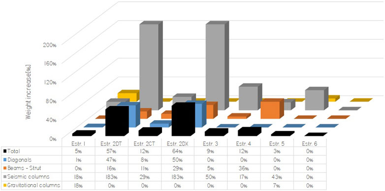
FIGURE 6. Disaggregation of the variation in the weight of the elements by structure.
Figure 7 shows the ratio of the weight increase of each group of elements to the total weight increase of the structure. The impact of each requirement on the weight increase has been evaluated by applying each requirement separately and maintaining the seismic demand fixed. It is to be noted that the effects of the seismic demand have not been evaluated separately since, in all cases, the increase in demand given by the design spectrum is very small, except for structure 2 on soil D. Thus, the increase in demand is mainly caused by changes in the load factors and inclusion of directional combinations.
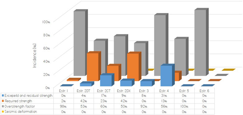
FIGURE 7. Incidence of design requirements on the variation of the weight of the structure.
Not only the structures increase their weight but also the anchor bolts increase the diameter up to 125%.
The seismic demand is characterized by pseudo-acceleration spectral ordinates at the first translational mode period, for both design and lateral displacement evaluation. In all structures except number 2, the seismic demand shows little or no variation among the designs made with the current and proposed design. For structure 2 on soil D, the spectral ordinates at the first mode differ significantly for the Y direction due to the reduction of the period and the fact that the spectrum for soil D is more demanding than the spectrum for soil III.
Despite the aforementioned observation, the base shear increases up to 30% for all structures, except for structure 2 on soil D, where the increase varies between 35% and 186%. The increase in base shear is driven by the increase in seismic masses.
Since in most of the structures the first mode is predominant, the fundamental period is used as a reference in each direction to identify the spectral acceleration ordinates associated with each structure. As an example, Figure 8 shows a comparison of design and reference pseudo-acceleration spectra, both horizontal and vertical.
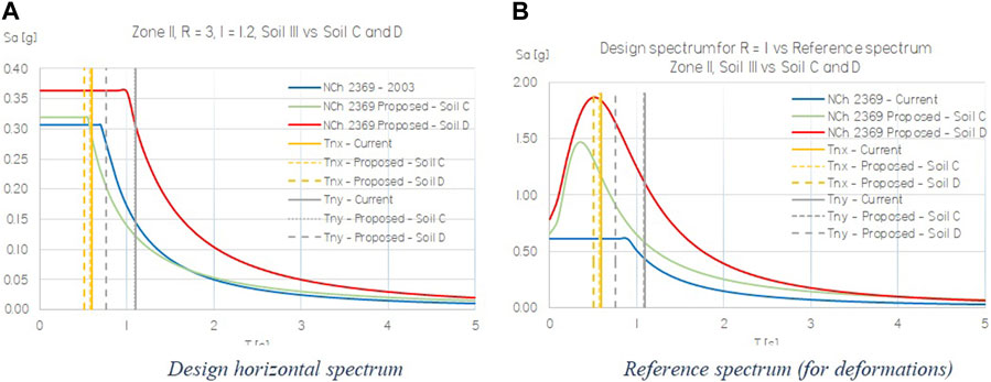
FIGURE 8. Seismic demand for structure II.
As a result of the increases in demand, the seismic displacements are increased between 25% and 138% in the structures designed according to the requirements of the proposed NCh2369. In general, the increases in displacement are smaller than the increase in base shear, which is mainly explained by the higher lateral stiffness of the seismic-resisting structure.
The application of the directional combinations increases the total demand on the structure since they include the vertical seismic component for all design purposes, unlike the current version where the vertical seismic component is only included in some well-defined cases for structure design. Thus, the directional combinations essentially increase the compressions and tensions in columns, braces, and anchorages.
6.2 Changes in performance
The weight increase in structural elements does not necessarily match the change in seismic performance, which is reflected on the non-linear static analyses. These analyses were conducted for each of the orthogonal principal directions, both in the positive and negative directions, for load patterns proportional to the first mode shape in each translational direction. For structure number 4, an additional diagonal direction is considered since for that direction, the greater effects on columns and anchorage are developed.
Each structure reached a failure mode at different roof drifts (higher than those corresponding to the maximum base shear). A 3% drift limit is considered for non-simulated failure modes since drifts higher than this limit are incompatible with the concentrically braced frame structural system. In addition, at high drifts, secondary structural mechanisms are developed once all braced panels of a level have reduced their load capacity. For instance, perpendicular frames take more load via torsion or moment frame behavior appears.
The failure modes in Table 2 are the expected bending moment in beams (Mpe beam), the expected bending moment in columns (Mpe column), maximum elongation or rupture elongation in anchor bolts (Elong per), and model convergence problems (converg). If an element of the structure reaches a failure mode, it does not imply the collapse of the structure because not all elements reach the failure mode at the same time.
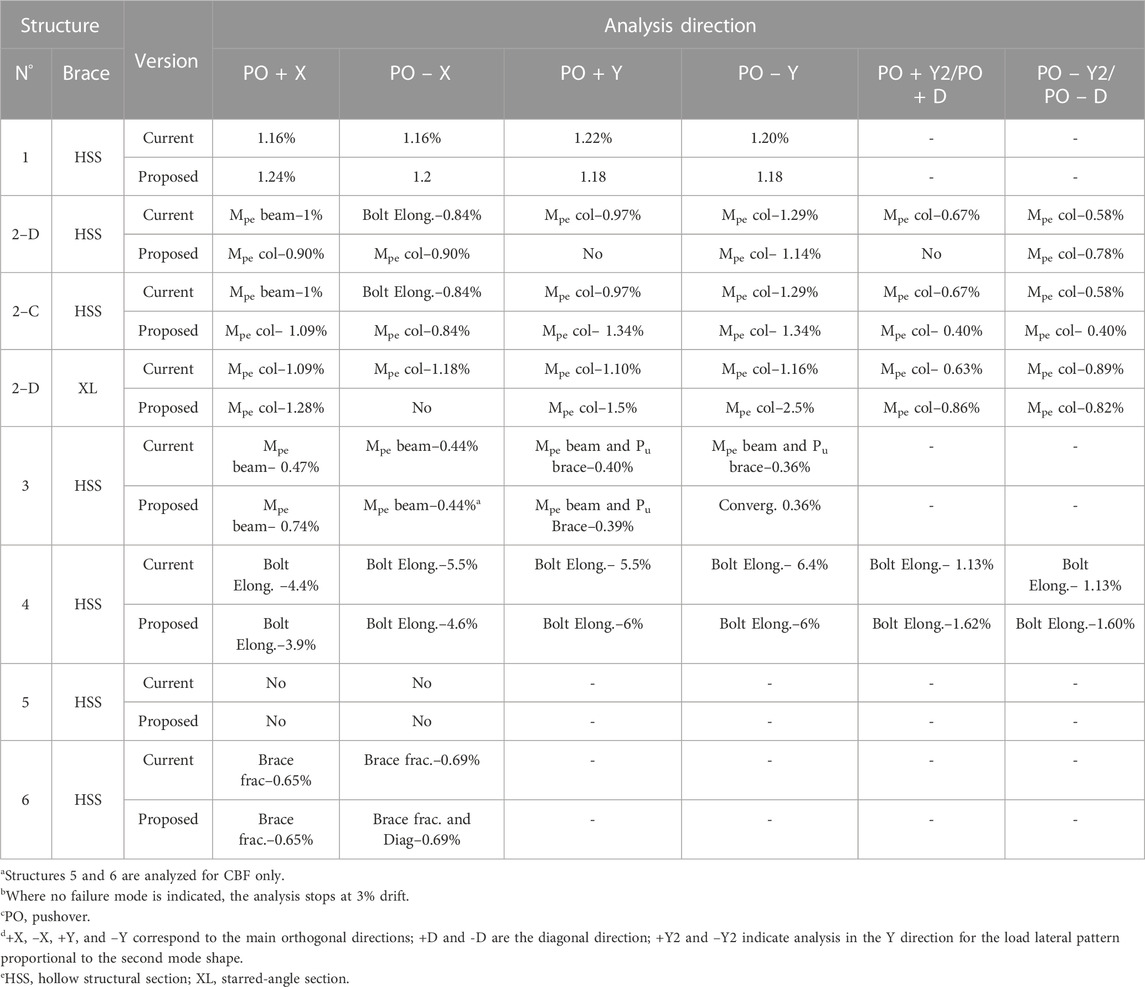
TABLE 2. Failure modes.
For all the non-linear static analyses (current and proposed version), the maximum base shear of the structure is associated with the maximum load on the braces. The exception to that is structure 1, where the failure is associated with the anchor bolts.
Figure 9 shows the interstory drifts achieved by the different models when the displacement capacity is reached, i.e., when a failure mode is detected. In general, buckling of the brace that controls the performance of the structure (usually the first level, critical panels) is reached between 0.2% and 0.5% drift. The braces of higher levels tend to buckle later than those of the critical panels. The buckling order of the braces and the maximum capacity (base shear) are the same for the proposed and current version of the standard NCh2369, but in the design made for the former version, the drift associated with the failure mode is usually greater than that for the latter version. For instance, in structure 3 designed with the current version, the expected capacity of the bending moment in inverted V braced beams, for analysis in the X direction, is reached at 0.47% drift versus 0.74% for the structure designed with the proposed version.
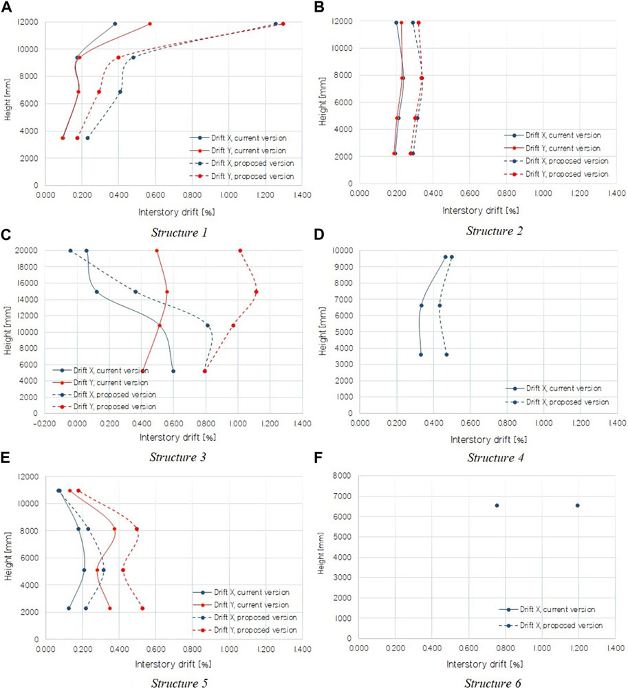
FIGURE 9. Interstory drifts at displacement capacity. (A) Structure 1; (B) Structure 2; (C) Structure 3; (D) Structure 4; (E) Structure 5; (F) Structure 6.
It is interesting to observe the elongation in anchor bolts because through them the structure develops early non-linearity. As mentioned by Herrera and Zúñiga (2019), small anchor bolts imply that fracture occurs at low drifts, while very large anchor bolts remain in the linear elastic range, generating the structure to develop non-linearity elsewhere.
As shown in Table 3, only structures 1 and 4, the latter for analysis in the diagonal direction, reach bolt breaking elongation at roof drifts below 3%. In the rest of the structures, the bolts remain in the linear range.
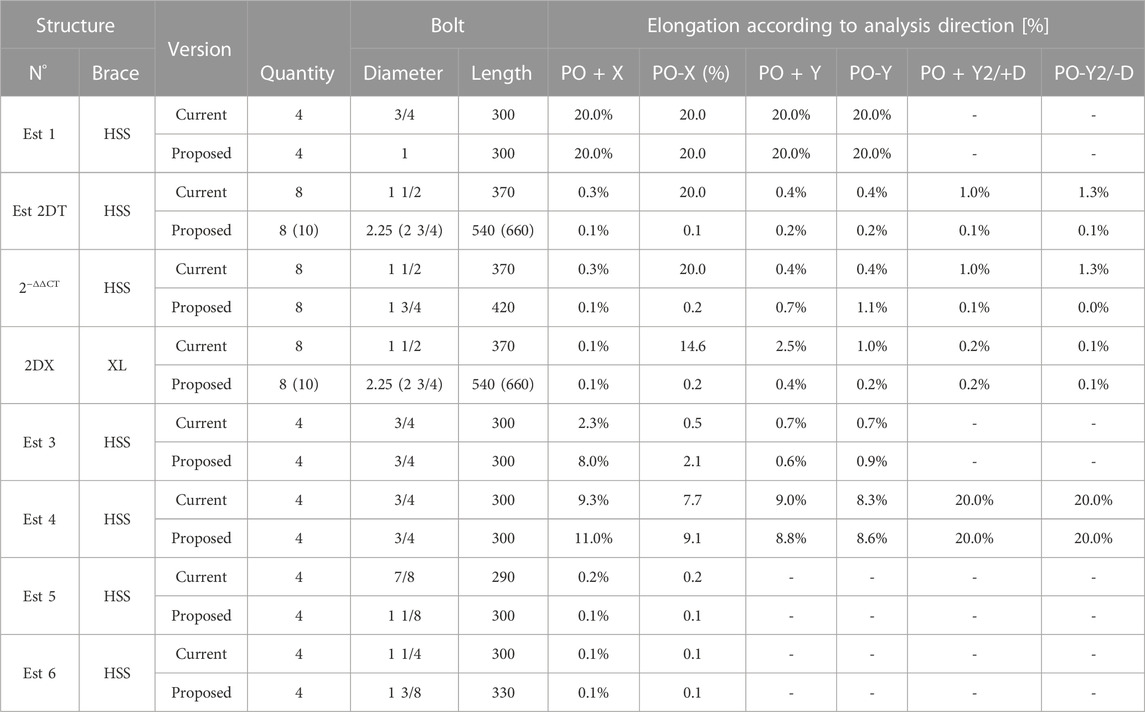
TABLE 3. Bolt elongation.
The performance parameters were obtained by the capacity spectrum method, where the demand is the reference spectrum defined in the current and proposed version. The reference spectrum was used since it is intended to represent a reasonable level of the expected seismic hazard.
As can be seen in Figure 10, all the structures, except number 2 on soil D, increase their shear capacity due to the increase in the cross-section of their elements (columns, braces, and beams of CBF). Structure 6 shows no variation in its shear capacity and no other performance parameters because the design of this structure was controlled by non-seismic load combinations. The increase in the maximum shear is consistent with the variations of weight of the elements of the CBF, explaining that structures 1, 2, 3, 4, and 5 in soil type C exhibit moderate increases (less than 12%). However, for structure 2 on soil D, the increase of maximum shear is approximately 60%, mainly due to the increase in demand.
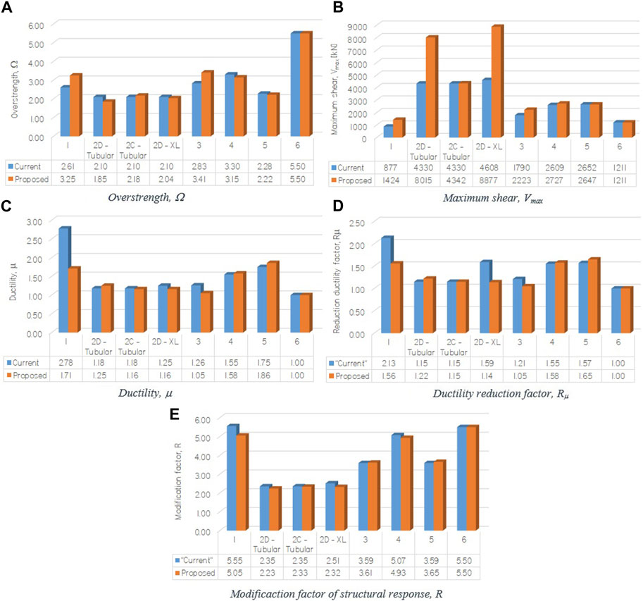
FIGURE 10. Performance parameters for each model: (A) Overstrength; (B) Maximum base shear; (C) Ductility; (D) Ductility reduction factor; (E) Structural response modification factor.
The overstrength increases and decreases for designs made for the proposed version versus those developed for the current version of NCh2369. The variations are small, and the decreases are mainly explained by the increase of the seismic mass.
Similarly, for the overstrength, the ductility demand, obtained from the capacity spectrum, decreases for four cases and increases for three cases, when comparing the designs according to the proposed version with the current version. The decreases do not necessarily mean that the structures have a decreased capacity to deform inelastically since, as mentioned previously, the drift at which the failure modes are developed in designs according to the proposed version of the NCh2369 standard is higher than that of designs according to the current version.
In terms of the effective structural response modification factor (R), there is no clear trend. It is interesting to note that in structures with small eccentricity in the mass distribution in plan, and limited irregularities in the stiffness distribution (1, 3, 4, 5, and 6), the R factor is higher than the one used for design (R = 4 for structure 6 and R = 3 for all the others).
When comparing the performance parameters of the designs made with the two versions of the standard (Figure 10), the proposed modifications do not necessarily improve the performance in terms of these parameters. However, the changes in the standard requirements are successful in preventing or postponing failure modes to higher drifts. Thus, if the performance is associated to the drift at which the failure mode develops, the tendency is an increase of this drift in the designs according to the proposed version of the NCh2369 standard.
Additionally, if the performance is associated with the accumulated energy from the pushover curve up to the failure mode, the same trend described previously is observed. Table 4 shows the percentage increase of the average drift at which the failure mode develops, and the accumulated energy (designs according to the proposed version versus the current version).
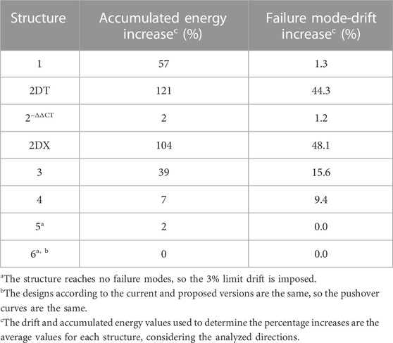
TABLE 4. Failure mode drift variation and accumulated energy.
6.3 Discussion
Four of the six structures satisfy the recommendations about regularity, redundancy, symmetry, complexity, and ductile response of the elements, described in Section 4.1 of the current (INN, 2003) and proposed version of the standard. These recommendations are intended to help meet the life safety objective set forth in the standard.
All structures have limited non-linear incursions, as indicated by the standard to satisfy the continuity of operation, which is one of the main performance objectives declared.
Considering the aforementioned objectives, the structures are grouped as follows:
• Structures with regularity in stiffness and mass (structures 1, 4, 5, and 6).
• Structures with high mass eccentricity and/or torsional problems, (structures 2 and 3).
Even though the structures investigated are six cases from the large mining industry, four of them are representative of structures included in the regulatory requirements. Thus, the results and general comments presented for these four structures are applicable to the CBF typology described in the current regulations.
The standard requirements aim to ensure that the structures will satisfy life safety and continuity of operation. The four structures that possess regularity and symmetry effectively achieve significant reserve strength and inelastic deformation capacity, allowing for life safety.
Regarding the continuity of operation of the structures, according to the limited non-linear incursion, the objective is satisfied. However, in many industrial facilities, the continuity of operation is associated with deformation limits imposed by large equipment or ducts, which are more restrictive than the regulatory limits. Therefore, it is appropriate to review the deformation limits established in the standard to ensure the continuity of operation of the structure–equipment assembly.
Regarding the two remaining structures, they increase the need for further analysis. Structure 2 raises the question: is the same R appropriate for structures that meet regularity requirements as for those that do not? Structure 3 suggests the need to establish normative requirements to avoid low redundancy configurations and significant stiffness discontinuities since these perturbations on structural configurations are relatively common in the industrial area, due to operational needs. Both structures are code-compliant, which indicates the need for further requirements to avoid this type of configurations.
7 Conclusion
This work evaluated the effect of modifications on the current Chilean seismic design code for industrial structures on the structural characteristics and seismic performance of CBFs. For this purpose, six industrial steel structures were designed using the current code and the proposed version. The performance was evaluated through static non-linear analyses in 3D models according to the methodology prescribed by the FEMA P695 standard (FEMAP695, 2009). The models included the non-linearity of braces, columns, beams or struts, and anchor bolts. Although the investigated structures are cases of facilities based on the CBF in the mining industry, four of them are representative of the normative requirements of regularity and symmetry, while the other two present deviations from these, such as irregularity in the distribution of stiffness and/or mass or low redundancy. Thus, the results can be generalized to the CBF typology described in the current standards.
From the performance parameters, Ω, μ, R μ, and R (Figure 10), it is not possible to establish that the modifications to the standards generate an improvement in seismic performance. However, if the average drift at which the failure mode develops and the energy accumulated by the structures until they reach the failure mode are compared, it can be concluded that the proposed modifications to the standard generate an improvement in performance.
The modifications to the seismic demand give the structure greater stiffness and more robust elements, particularly affecting braces. The change in soil classification is not significant, at least in the soils considered, except for structure 2, where due to lack of information to select the correct soil in the proposed version, two types of soil were studied, namely, C and D. The results using soil C showed the same trend as the other structures, that is, low incidence in the increase in demand, while soil D generated a significant increase in demand, in the weight of the structure and a notable increase in the maximum shear. The increase in demand was associated with the increase in the load factor (1.1 according to the current version and 1.4 according to the proposed version) and the inclusion of directional combinations, where the three earthquake directions are always combined in different proportions.
The inclusion of the overstrength was shown to be the most incident, generating an increase in the column cross-sections. The overstrength factor allows the columns to maintain a nearly elastic response, while other structural elements develop non-linearities (but no buckling).
The requirements about V or inverted V bracing, and particularly its beams, proved to be effective in preventing beam plastification in bending or relegating the plastification of the beams to larger drifts.
The requirements for struts (beams) in X braced frames did not show significant effects on the design outcome since most of the struts are part of the platforms.
Other modifications such as those related to the sizing of struts in cross-braced systems, or the elimination of the limitation of seismic demand in compression of the braces to 80% of the brace capacity, did not show significant effects on the sizing or performance.
When looking at the increase in accumulated energy or the increase in the drift at which the failure mode develops (Table 4) and the increase in weight of the structures (Table 4 or Figure 6), a rough trend is observed, which is, the greater the increase in weight of the structure, the greater the increase in stored energy.
It is important to note that, except for structure 2 evaluated for soils III vs D, the increase in weights is moderate (less than or equal to 12%). Thus, if the performance is measured as the increase in accumulated energy (up to 57%), the weight increase of the structures is beneficial. It is also beneficial if performance is measured as the increase in drifts at which failure modes develop, as it relegates to higher drifts or eliminates the failure mode.
For structure 2 evaluated for soils III vs D, the beneficial effect is accentuated, so although the weight increases are significant (between 57% and 64%), the increase in accumulated energy is very significant, between 104% and 121%, as is the drift associated with the failure mode, between 44% and 48%.
Footnotes
It is important to note that, given the dynamic process of revision and modification of the standard, the provisions of the proposed version of the NCh2369 standard, as of May 2020, were used as a frame of reference for the research. Hereinafter, this version may be cited as “design according to proposed version,” “proposed design,” or by the reference (INN, 2020).
Data availability statement
The raw data supporting the conclusion of this article will be made available by the authors, without undue reservation.
Author contributions
RR is the main author, having developed the calibrations, modeling, data manipulation, analysis of results, and conclusions. RH has been the supervisor of the work, participating in the analysis of the results and discussion of the conclusions. All authors contributed to the article and approved the submitted version.
Acknowledgments
This work is part of the master’s thesis of the principal author, RR, developed at the University of Chile.
Conflict of interest
The authors declare that the research was conducted in the absence of any commercial or financial relationships that could be construed as a potential conflict of interest.
Publisher’s note
All claims expressed in this article are solely those of the authors and do not necessarily represent those of their affiliated organizations, or those of the publisher, the editors, and the reviewers. Any product that may be evaluated in this article, or claim that may be made by its manufacturer, is not guaranteed or endorsed by the publisher.
References
Aguero, A., Izvemari, C., and Tremblay, R. (2006). Modeling of the seismic response of concentrically braced steel frames using the opensees analysis environment. Adv. Steel Constr. 2 (3), 242–274. doi:10.18057/IJASC.2006.2.3.5
AISC (2005a). Seismic Provisions for structural steel buildings, ANSI/AISC 341-05. Chicago, Illinois: American Institute of Steel Construction.
AISC (2010a). Seismic provisions for structural steel buildings, ANSI/AISC 341-10. Chicago, Illinois: American Institute of Steel Construction.
AISC (2010b). Specification for structural steel buildings, AISC/ANSI 360-10. Chicago, Illinois: American Institute of Steel Construction.
ASCE (2013). Seismic evaluation and retrofit of existing buildings, ASCE/SEI 41-13 (2013). Chicago, Illinois: American Institute of Steel Construction.
Astica, G. (2012). Evaluación de las disposiciones de diseño sísmico para marcos arriostrados en edificios industriales (Santiago, Chile: Universidad de Chile). Civil Engineering Thesis.
ATC 19 (1995). “Structural response modification factors”. Redwood City, CA: Applied Technology Council.
ATC 40 (1996). “Seismic evaluation and retrofit of concrete buildings,”. Report No:SSC 96-01 (Redwood City, CA: Applied Technology Council).
Auger, K. (2017). Conception Parasismique Des Contreventements Concentriques En Treillis À Segments Multiples Combinés Aux Poteaux Gravitaires, Mémoire de maîtrise. Montreal, QC: École Polytechnique de Montreal.
Black, G. R., Wenger, B. A., and Popov, E. P. (1980). “Inelastic buckling of steel struts under cyclic load reversals,”. Report No: UCB/EERC-80/40 (Berkeley, California: Earthquake Engineering Research Center).
Bruneau, M., Uang, C.-M., and Sabelli, R. (2011). Ductile design of steel structures. 2. New York, United States: McGraw-Hill.
Chávez, N. (2012). Revisión de los criterios de diseño de pernos de anclaje (Santiago, Chile: Universidad de Chile). Civil Engineering Thesis.
CSI (2011). CSI analysis reference manual for SAP2000, ETABS, SAFE and CSIbridge. Berkeley, California: Computers and Structures Inc.
D'Aniello, M., La Manna Ambrosino, G., Portioli, F., and Landolfo, R. (2013). Modelling aspects of the seismic response of steel concentric braced frames. Steel Compos. Struct. 15 (15), 539–566. doi:10.12989/scs.2013.15.5.539
FEMA356 (2000). Prestandard and commentary for the seismic rehabilitation of buildings. Washington, D.C: Federal Emergency Management Agency. FEMA356.
FEMA440, (2005). Improvement of nonlinear static seismic analysis procedures. Redwood City, CA: Applied Technology Council.
FEMA P695, (2009). Quantification of building seismic performance factors. Washington, D.C: Federal Emergency Management Agency.
Herrera, R., and Zúñiga, J. (2019). “Efecto de las modificaciones a NCh2369 en el diseño y desempeño de marcos de acero arriostrados concéntricamente,” in Proceedings of the XII Congreso Chileno de Sismología e Ingeniería Antisísmica, Valdivia, Chile, April 2019.
Herrera, R., Guerrero, R., and Rodriguez, M. A. (2022). “Experiments and modelling of starred angle braces,” in Proceedings of the 10th international conference on behaviour of steel structures in seismic areas. STESSA 2022. Editors F. M. Mazzolani, D. Dubina, and A. Stratan (Cham: Springer), 262. Lecture Notes in Civil Engineering. doi:10.1007/978-3-031-03811-2_18
Imanpour, A., Auger, K., and Tremblay, R. (2016a). Seismic design and performance of multi-tiered steel braced frames including the contribution from gravity columns under in-plane seismic demand. Adv. Eng. Softw. 101, 106–122. doi:10.1016/j.advengsoft.2016.01.021
Imanpour, A. (2015). Seismic response and design of steel multi-tiered concentrically braced frames (Montréal, Qc: École Polytechnique de Montréal). Thèse de doctorat.
Imanpour, A., Tremblay, R., and Davaran, A. (2012). “Seismic evaluation of multi-panel steel concentrically braced frames,” in 15th World Conference on Earthquake Engineering (15WCEE), Lisbon, Portugal, 24-28 September 2012.
Imanpour, A., Tremblay, R., Fahnestock, L. A., and Stoakes, C. (2016c). Analysis and design of two-tiered steel braced frames under in-plane seismic demand. Analysis Des. Two-Tiered Steel Braced Fram. under In-Plane Seismic Demand. J. Struct. Eng. 142. doi:10.1061/(ASCE)ST.1943-541X.0001568
Imanpour, A., and Tremblay, R. (2016b). “Seismic design procedure for steel multi-tiered concentrically braced frames beyond CSA S16 limit,” in Proceedings of the canadian society for civil engineering annual conference 2016: resilient infrastructure, London, ON, Canada.
INN (2010). Diseño estructural - disposiciones Generales y Combinaciones de carga, NCh3171.Of2010. Santiago, Chile: Instituto Nacional de Normalización.
INN (2012). Diseño sísmico de edificios, NCh433.Of1996. Modificada en 2012. Santiago, Chile: Instituto Nacional de Normalización.
INN (2003). Diseño Sísmico de Estructuras e Instalaciones Industriales, NCh2369.Of2003. Santiago, Chile: Instituto Nacional de Normalización.
INN (2020). Proyecto de Norma de Diseño Sísmico de Estructuras e Instalaciones Industriales, NCh2369. Santiago, Chile: Instituto Nacional de Normalización.
Rodríguez, M. (2020). Desempeño sísmico de estructuras industriales de marcos multi-panel arriostrados concéntricamente, MTBF (Santiago, Chile: Universidad de Chile). M.S. Thesis.
Riquelme, R. (2022). Efectos de las modificaciones a la demanda y requisitos de diseño de la norma NCh2369 sobre el dimensionamiento y desempeño sísmico de estructuras industriales de marco arriostrado (Santiago, Chile: Universidad de Chile). M.S. Thesis.
Takamatsu, T., and Tamai, H. (2005). Non-slip type restoring force characteristics of an exposed-type column base”. J. Constr. Steel Res. 61 (7), 942–961. doi:10.1016/j.jcsr.2005.01.003
Tremblay, R., Archambault, M.-H., and Filiatrault, A. (2003). Seismic response of concentrically braced steel frames made with rectangular hollow bracing members. J. Struct. Eng. 129 (12), 1626–1636. doi:10.1061/(asce)0733-9445(2003)129:12(1626)
Uriz, P., Filippou, F. C., and Mahin, A. (2008). Model for cyclic inelastic buckling of steel braces. J. Struct. Eng. 134 (4), 619–628. doi:10.1061/(asce)0733-9445(2008)134:4(619)
Uriz, P., and Mahin, S. (2008). “Towards earthquake-resistant Design of concentrically braced steel-frames structures,”. PEER Report 2008/08 (Berkeley: University of California). Pacific Earthquake Engineering Research Center.
Urzúa, C., and Herrera, R. (2017). “Comparison of the seismic behaviour of two industrial steel structures designed in accordance with Chilean practices and AISC requirements,” in Proceedings of the 16th World Conference on Earthquakes, Santiago Chile, January 9-13th, 2017. Paper N° 514.
Keywords: seismic performance, seismic design, industrial facilities, non-linear analysis, steel structures, concentrically braced frames, Chilean standards
Citation: Riquelme R and Herrera R (2023) Seismic performance of Chilean concentrically braced frame industrial structures: effects of recent code modifications. Front. Built Environ. 9:1155915. doi: 10.3389/fbuil.2023.1155915
Received: 31 January 2023; Accepted: 21 July 2023;
Published: 16 August 2023.
Edited by:
Stefano Silvestri, University of Bologna, ItalyReviewed by:
Antonio Formisano, University of Naples Federico II, ItalyFrancisco López Almansa, Universitat Politecnica de Catalunya, Spain
Copyright © 2023 Riquelme and Herrera. This is an open-access article distributed under the terms of the Creative Commons Attribution License (CC BY). The use, distribution or reproduction in other forums is permitted, provided the original author(s) and the copyright owner(s) are credited and that the original publication in this journal is cited, in accordance with accepted academic practice. No use, distribution or reproduction is permitted which does not comply with these terms.
*Correspondence: Ricardo Herrera, cmloZXJyZXJAaW5nLnVjaGlsZS5jbA==