 Hamza Al-Fhaid
 Walid Fouad Edris
 Mahmoud Al-Tamimi1
- 1Earth and Environmental Sciences Department, Science Faculty, Yarmouk University, Irbid, Jordan
- 2Civil Engineering Department, Hijjawi Faculty for Engineering Technology, Yarmouk University, Irbid, Jordan
- 3Civil Engineering Department, Giza High Institute of Engineering and Technology, Giza, Egypt
This research aims to produce a compressed Earth block (CEB) product locally from soil collected from North Jordan. The CEB mixture was further stabilized using oil shale (OS) and ordinary Portland cement (OPC). The CEB specimens were thoroughly characterized by studying their mechanical properties (compressive and flexural strength) and durability characteristics (erosion, absorption, and shrinkage tests). Eight mixtures were carried out for the CEB, one of which was the control mix. The other mixtures were carried out by replacing soil with OS, cement, and sand in different proportions. The results showed that higher compressive strength and flexural strength for CEB were obtained in the mixtures that contained 10% of OS and 10% of cement, resulting in an average compressive strength of 10.6 MPa and flexural strength of 0.25 MPa. The absorption increased when the OS increased in the soil. The consequent erosion test was related to the absorption test, where the higher the absorption, the more negative the results of the erosion test. Moreover, oil shale improved the shrinkage properties of the CEB, as the higher the proportion of oil shale in the CEB, the lower the shrinkage. Finally, using oil shale as a stabilizing agent in soil had a clear role in improving the mechanical properties, hiding the shrinkage cracks, and reducing the volume shrinkage value of the CEB.
1 Introduction
One of the earliest building techniques is the utilization of subsoil, providing simple houses using freely available materials (Jaquin, 2012). The majority of Earth materials are taken out of subsurface horizons. However, some are taken out of soft rock deposits. Topsoil is susceptible to degradation and shrinkage, making it inappropriate for use in construction (Reinhardt and Grosse, 2004). Earth construction is now associated with poverty (Fernandes et al., 2019), and the majority of such structures are found in poor countries (Teixeira et al., 2020). Compared to the conventional construction technique, the usage of the Earth building technique could result in a 50% reduction in potential environmental impact (Fernandes et al., 2019).
Compressed Earth blocks (CEBs) are one of the most widespread earthen building techniques. Earth blocks have seen somewhat of a renaissance during the past 70 years, becoming more widely utilized after being redeveloped (Lenci et al., 2012). CEB is an approach that creates blocks that are appropriate for current construction procedures by combining stabilizing ingredients with damp soil and pressing the mixture into a mold. The CEB can be large or small and flat or interlocking, and their color varies depending on the stabilizer and the soil used. The notion of compacting the soil dates back thousands of years, and the earliest compressed Earth blocks were made using wooden pestles. In addition to enhancing the quality and function of the blocks (Taallah et al., 2014), earthen compaction has numerous positive effects on the environment, society, and the economy (Saidi et al., 2018; Chaibeddra and Kharchi, 2019).
Jordan has a huge energy resource in the form of vast oil shale reserves (approximately 65 billion tons of geological reserves) (Alali, 2015). Oil shale (OS) is a fine-grained, organic-rich sedimentary rock (mostly carbonates; chalk marl and shale) that contains kerogen (Yihdego et al., 2018). OS is a calcium-rich solid fuel with a poor calorific value, and approximately 40–50 wt% of the processed shale remains as solid waste, the majority of which is landfilled (nearly 98%) (Paaver et al., 2019). Calcite or quartz is the main mineral component of OS, with kaolinite and apatite as secondary components, and feldspar, muscovite, illite, goethite, and gypsum as minor components (Alali, 2015). Chen et al. (2020) studied the possibility of using oil shale waste residue in pavement engineering in China through a Marshall test, rutting test, and splitting test by exploring the alternative particle size range of oil shale waste. The test results showed that the oil shale waste residue instead of the fine aggregate in asphalt mixture can not only effectively utilize the oil shale waste but also improve the engineering performance of asphalt pavement. Al-Otoom (2006) investigated the possibility of using oil shale in the production of Portland clinker. The results showed that the oil shale ash can be used in the manufacturing of Portland cement clinker. This study recommends a blending ratio of 16% oil shale ash, 18% kaolinite, and 66% calcite to maximize the benefits of using Jordanian oil shale. Wei et al. (2019) conducted a study on the feasibility of modifying silty clay as a subgrade material with waste fly ash and oil shale ash. The results showed that the physical properties of silty clay are improved by the addition of fly ash and oil shale ash; thus, the silty clay modified by fly ash and oil shale ash has the potential to be used as a viable subgrade material.
More than a hundred ingredients, including sand, gravel, cement, lime, bitumen, resins, volcanic tuff, sodium silicate, fibers, and geopolymer, are used to stabilize raw soil (Houben et al., 1994; Nshimiyimana et al., 2018; Sore et al., 2018; Edris et al., 2020; Edris et al., 2021). By forming bonds between the aggregate particles by hydration, cement stabilization increases mechanical strength and water resistance (Doat et al., 1979; Jayasinghe and Kamaladasa, 2007; Venkatarama et al., 2011). The primary goal of this research is to assess how OS and cement affect the mechanical characteristics and durability properties of compressed Earth blocks.
1.1 Research significance
Building with CEBs is becoming more popular due to their environmentally friendly process, low cost, and relative abundance of materials at the present time. Environmental issues related to cement production and durability or stiffness concerns regarding its application to soil constitute a significant motivation behind developing new binders. The research significance is based upon the urgent need of most developing countries (e.g., Jordan and Egypt) to build more durable and low-cost houses by using locally available materials. Weak soils are a source of problems for Earth building, such as their low strength. Research has been conducted to solve such problems through soil stabilization. Different types of stabilizers have been used. Cement and lime are more common stabilizers to enhance the mechanical properties of CEB. The emerging binder of OS is a promising construction material. It was intended to use this binder in the current study to stabilize weak clay soil. The objective of this research was to observe the effect of OS as a new stabilizer material on the properties of CEB. In addition, this research investigates the durability and mechanical properties, including the compressive and flexural strengths, of the local CEBs manufactured from soil in Jordan.
2 Materials and methods
Natural soil, OS, cement, and water were used as materials in this study.
2.1 Natural soil
A soil sample was taken from Kutum town in Jordan with coordinates of 32° 25′ 44.6″ N and 35° 54′ 04.2″ E. The natural soil, as visually described, is dark brown to red in color and mostly consists of clay-sized particles (Figure 1). All the collected soil samples were air-dried and sieved through sieve #4 before performing different laboratory tests to identify the geotechnical characteristics of the soil. The natural soil samples were subjected to a set of laboratory tests (e.g., sieve analysis, plastic limit, liquid limit, XRD, and XRF). Grinding and sieving at sieve # 120 (0.125 mm) were part of the sample preparation for (XRD and XRF). Before testing, the XRF sample was also dried for 2 h at 105°C.
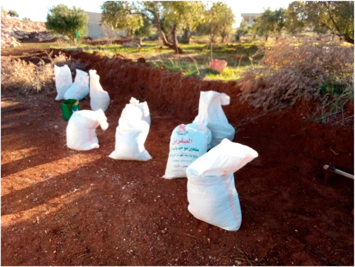
FIGURE 1. Clay-rich soils sampling site from Kutum town.
Wet laser granulometry measurement was used with sieving to determine the materials’ particle sizes. The coarsest >75 μm particles were subjected to sieving at the University of Yarmouk’s Geotechnical Laboratory. The Fritsch Analyst 22 Micro-Tec Plus Analyzer was used to perform laser granulometry at the size analyzer of the laboratory of the University of Yarmouk Department of Earth Sciences. The finest particles (those less than 75 μm) were distributed according to grain size using this procedure.
The Atterberg limits were carried out on the soil and soil replaced by 20% with OS according to ASTM D4318-10 (2010). The Atterberg limits were performed using the Casagrande apparatus on a material with a particle size of less than 425 μm in the Geotechnical Laboratory of the University of Yarmouk. The Atterberg limits enabled the plasticity index (PI) to be calculated, i.e., PI = LL—PL. The period during which the soil material is still formable was described by PI. The soil sample was evaluated for compatibility in the plasticity chart using the Atterberg limits values based on the Spanish standard (UNE 41410, 2008). The plasticity index and liquid limit values demonstrate the acceptability of the soil and soil replaced by 20% with OS for the production of compressed Earth blocks, as shown in (Figure 2). In accordance with the American Association of State Highway and Transportation Officials (AASHTO), the soil sample was classified as A-7-6 (2009).
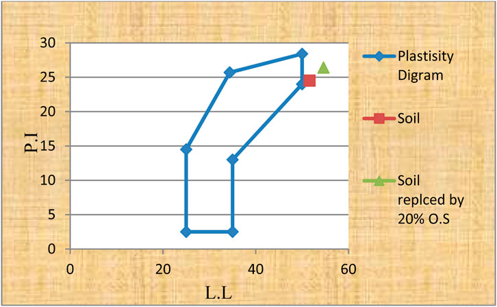
FIGURE 2. The standard diagram of Plasticity.
Clay in the soil contributes to its plasticity. The liquid limit of soil varies according to the amount and type of clay minerals present. A liquid limit test was conducted on a sample of the natural soil under study as part of the soil geotechnical characterization. Two soil samples were plotted on the diagram, and the diagram (Figure 2) shows both soil samples nearly considered as standard samples. The grain size distribution obtained from the sieve analysis was plotted on a semi-log graph paper, with the grain size plotted on the log scale and percent finer plotted on the natural scale. Figure 3 shows the grain size distribution for the largest particle size of the soil sample. The grain size distribution for the fine particles of the soil sample (silt and clay) was carried out by wet laser granulometry, and the result is shown in Figure 4. The soil contained a significant amount of clay and silt particles; as a percentage, clay was 37.3%, silt was 36%, sand was 24.4%, and gravel was 2.3%.
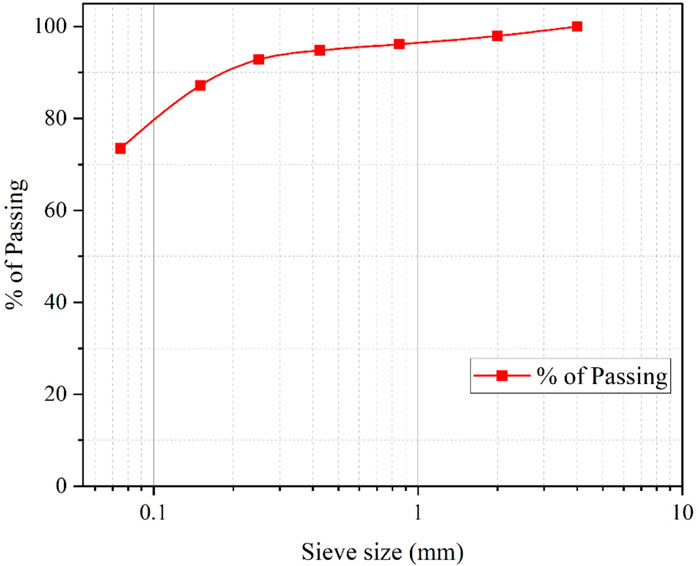
FIGURE 3. Grain-size distribution for the largest particle of soil sample.
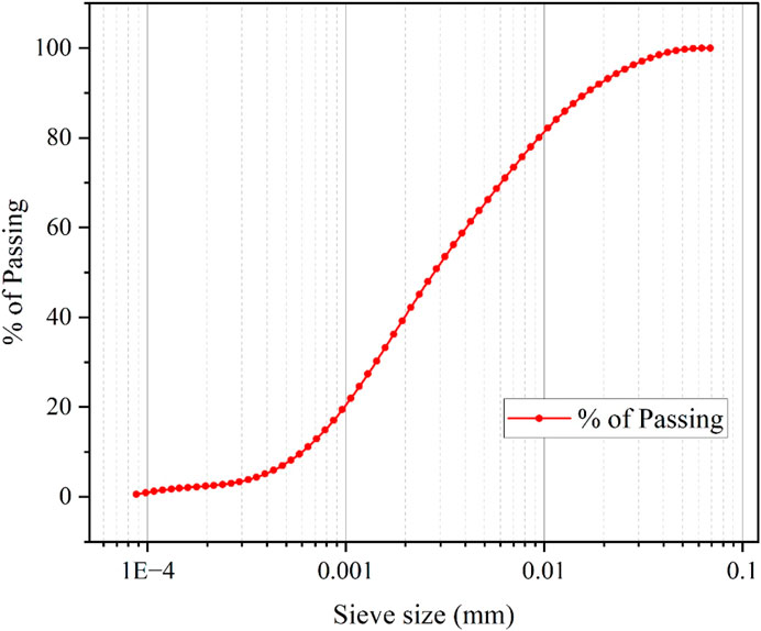
FIGURE 4. Grain-size distribution for the finest particle of the soil.
In general, the soil in the Irbid area is clayey, with a high expansion coefficient, and it may not be ideal for CEB manufacture. The particle size distribution of the fine particles of the soil sample (Figure 5) did not correspond to the recommended grain size range for CEB production (UNE 41410, 2008). Therefore, 30% of the soil was replaced with sand, which has a particle size distribution, as shown in (Figure 6), to bring it up to standards. Figure 7 depicts the particle size curve of the fine soil particles with the addition of sand to the soil; the particle size curve of the soil–sand mixes moved closer to the recommended grain size range for CEB production because the added sand, with particle sizes ranging from 0.85 to 0.075 mm, was used to compensate for the missing sizes in the fine soil. The geotechnical test results are summarized in Table 1.
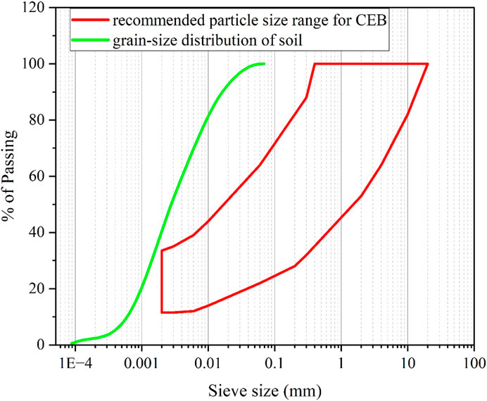
FIGURE 5. Grain-Size Distribution of the silt and clay particle of the soil. The red borders corresponded to the recommended particle size range [UNE 41410 (2008)].

FIGURE 6. Grain-size distribution of the sand.

FIGURE 7. Grain-size distribution of silt and clay replaced by 30% sand.
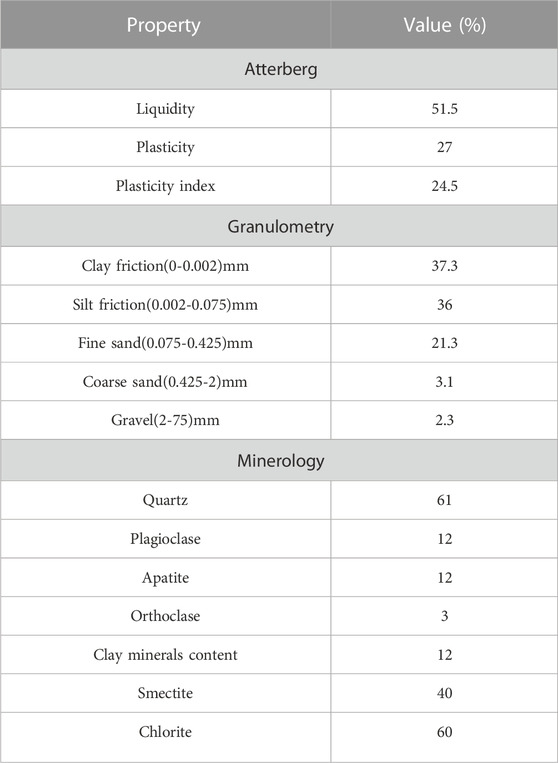
TABLE 1. Geotechnical characterization of the natural soil.
The chemical composition of the soil is shown in Table 2. Compared with red soil that has been used by (El-Hasan et al., 2019), there was great similarity in the oxides, including silicon, aluminum, manganese, iron, and potassium oxide.

TABLE 2. XRF result of the soil.
The XRD result of the soil is shown in Figure 8. The main band reflections indicate that quartz was the most abundant mineral. Other available minerals were apatite, plagioclase, orthoclase, chlorite, and smectite (montmorillonite).

FIGURE 8. The XRD result of the soil.
2.2 Cement
The cements utilized in this study were OPC type I of grade 42.5 with a specific gravity of 3.26 and fineness modulus 2.03%, and the chemical composition is shown in Table 3.

TABLE 3. The chemical composition of OPC.
2.3 Oil shale
The study area was located in Irbid Governorate City, about 12 km northeast of Irbid City, with coordinates of 32° 37′ 26.07″ N and 35° 56′ 32.36″ E. The Wadi Shillalah Formation (WSF) is mostly exposed in this study (Figure 9). OS samples were collected horizontally along the outcrop. For technical reasons, the samples were taken at a depth of 10–20 cm, as freshly as feasible. The WSF is made of gray to white chalk, with big lenses of dark grey chalk indicating the organic content (Al-Tamimi et al., 2021). The samples were crushed by a ball mill in the Department of Civil Engineering at Yarmouk University and sieved using sieve #200. The chemical composition of this OS is shown in Table 4.
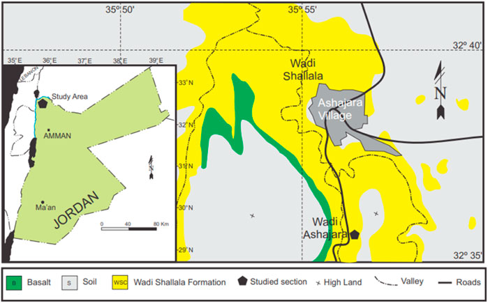
FIGURE 9. Geological map of the study area shows the exposed formations within study area (Al-Tamimi et al., 2021).

TABLE 4. The chemical composition of OS.
The XRD result of the OS is shown in Figure 10. The main band reflections indicate that calcite was the most abundant mineral. Other available minerals were apatite, anhydrite and kaolinite.
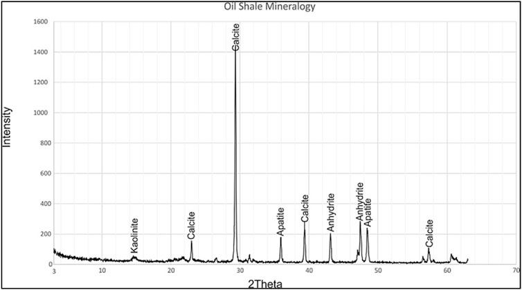
FIGURE 10. The XRD result of the OS.
2.4 Experimental program
A schematic diagram of the methodology is shown in Figure 11.
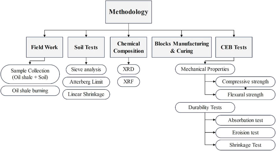
FIGURE 11. A schematic diagram of the methodology.
2.4.1 Production of CEB
The soil samples were extracted from the village of Kutum, and exploratory mixtures were made using stabilizers such as cement, lime, and oil shale. The samples were cast into small molds and then visually examined 3 months after casting.
• The soil sample without additions had a complete collapse, and there was no bonding between the particles (Figure 12A).
• The samples to which oil shale was added by 20% (Figure 12B) and 30% (Figure 12C) showed a clear improvement in the shrinkage property as there was a complete absence of shrinkage cracks.
• The use of oil shale with lime together as stabilizers was considered not appropriate because of the shrinkage cracks that appeared when used together (Figure 12D).
• The use of oil shale with cement together as stabilizers was considered appropriate because of the lack of shrinkage cracks (Figure 12E).
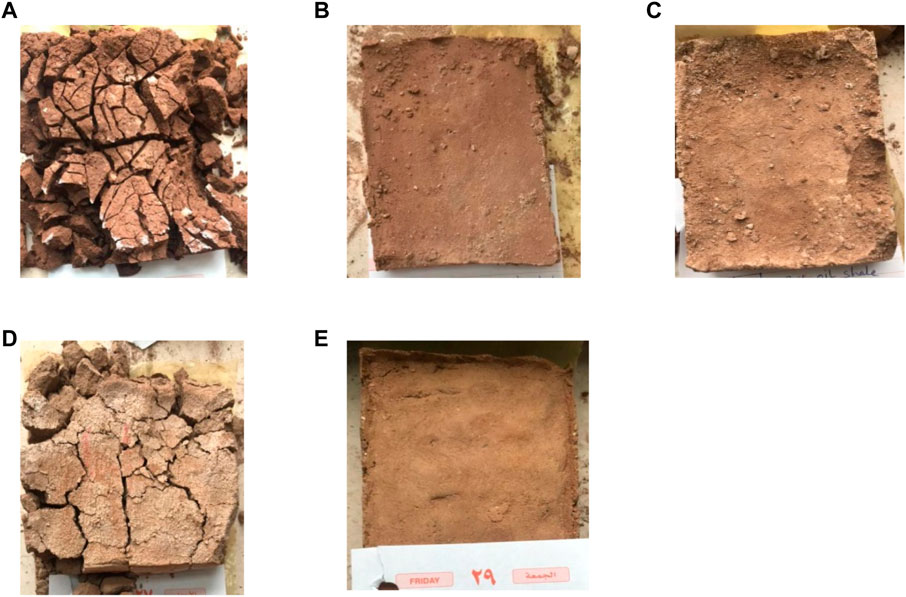
FIGURE 12. Visual properties of experimental samples. (A) soil sample without additions, (B) 20% OS, (C) 30% OS, (D) OS with lime, (E) OS with cement.
Based on these results, the use of lime with oil shale was excluded, and the study plan was determined, as shown in the next part.
2.4.2 Batch design and schedule for CEB
OS stabilizer was used at 10% and 20% by weight. A total of nine batches were made using various ingredient combinations. In seven batches, the original soil was replaced with 30 percent by weight of sand. The last remaining batch was completely composed of local soil (S mix). The schedule is shown in Table 5.
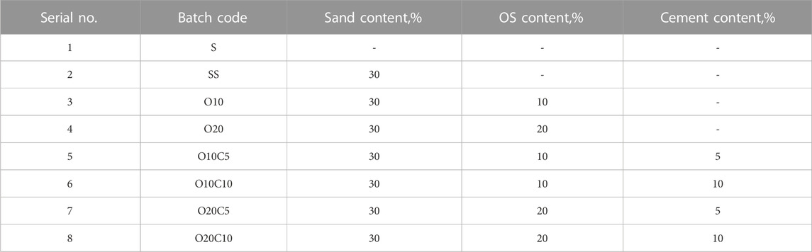
TABLE 5. CEB batch schedule (OS stabilizer).
Every batch has a unique code that indicates all the details of its contents. Batch No. 7 will be used as an example to demonstrate.
(O20C5)
O: Oil shale.
O20: The OS existence; in 20% by weight.
C: Cement.
C5: The cement content; in 5% by weight.
Sand content is 30% by weight.
Soil content is 45% by weight.
[Note: all samples contain 30% sand by weight, except for the control sample (S mix)].
2.4.3 Block manufacturing and curing
The shape and size were mostly determined by a diverse set of criteria, including the type of construction, available molds, and local customs. The compaction machine was manually controlled and had a mold size of 300 mm × 150 mm × 80 mm (Figure 13). Manual compaction is the compaction technique used to press the block, and the compaction force was calculated using the ratio approach and cannot be expressed in MPa (Figure 14). This type of machine compaction ratio should not be less than 1.70. The compaction ratio = (H)/(T), where H is the highest of loosely packed mix (Hall et al., 2012). In the machine mold, T is the block thickness, and in this machine H = 13.7 cm and T = 8 cm on average, while the compaction ratio was 1.70. The appropriate water content was determined by utilizing the drop test according to (ASTM D6780/D6780M-19, ASTM, 2019).
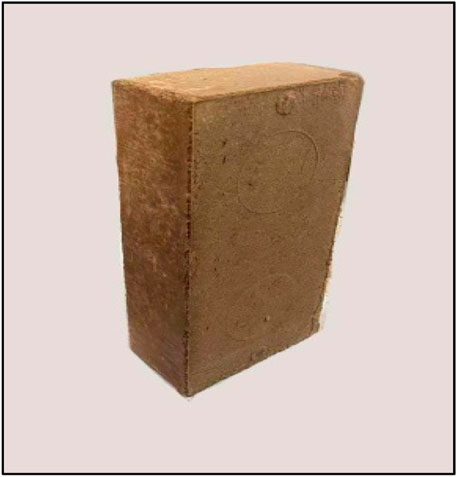
FIGURE 13. 300 mm × 150 mm × 80 mm block dimension.
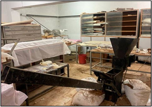
FIGURE 14. Manual compressions machine.
The samples were treated using water sprinkling after block manufacture to prevent shrinkage fractures. As indicated in Figure 15, they were sealed with plastic sheets and cured at room temperature. At the end of week, four of the plastic sheets were removed, and the blocks were exposed to air.
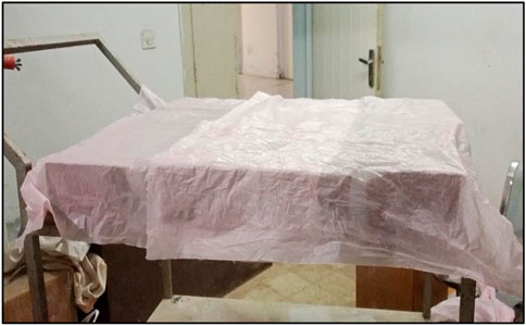
FIGURE 15. Curing process of CEB.
2.5 CEB tests
Before the testing campaign, the blocks were kept in ambient laboratory settings for roughly a month, with a relative humidity of 47% and a temperature of 22°C ± 5°C. In accordance with Australian Bulletin 5 (Middleton and Schneider, 1987), all specimens were dried at 105°C for 24 h and then placed in the ambient laboratory for roughly 2 h before being evaluated to reduce the effect of moisture content on their mechanical qualities.
2.5.1 Compressive strength
The compressive strength test was the most critical test performed on the CEB. The compressive strength ratings are commonly used to determine the block’s properties. As shown in Figure 16, a Matest Compression Machine of 2000 KN was used to test the compressive strength of the material. The test was carried out at a 0.05 MPa/s loading rate [ASTM D4318- 10 (2010)]. The dry density of each specimen was regularly assessed throughout the preparation for each test using the averaged exterior dimensions and oven-dry mass of each specimen. All blocks were tested in compression capped with 4 mm-thick sheets of rubber to get a genuine and accurate reading for the compressive strength result (Ruiz et al., 2018). After 28 days of manufacture, three specimens were tested, and the average value was taken.
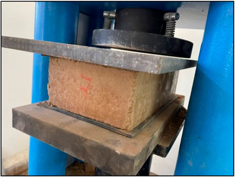
FIGURE 16. Compressive strength test preparation.
2.5.2 Flexural strength test
The flexural strength test, also known as the modulus of rupture, determines the ability of the blocks to resist bending forces. The test also was carried out with a Matest Compression Machine of 2000 KN compression machine, as illustrated in Figure 17, at a loading rate of 0.05 MPa/s. Before it was tested, the dried specimens were placed in an oven set at 110°C for 24 h and then left in the air for around 2 h. After 28 days of manufacturing, three specimens were tested, and the average value was recorded.
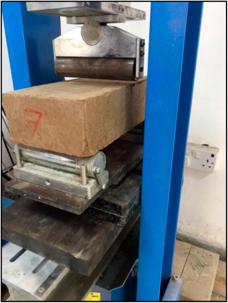
FIGURE 17. Flexural strength test preparation.
2.5.3 Absorption test
Acknowledging a block’s water absorption value is crucial since it can be used to approximate a block’s void content (Taallah et al., 2014). Therefore, water absorption is a significant test of the CEB. It is defined as the amount of water that a CEB can absorb after soaking in water for 24 h, as shown in Figure 18. The water absorption test is conducted based on AFNOR XP, P13-901 (AFNOR, 2001). The percentage of water absorbed is calculated using the relative difference in the weight percentage when compared to the dry block weight, as shown in the following formula:
where A [%] is the relative difference in percentage in weight that is compared to the dry block weight, Wh is the wet block weight (g), and Ws is the dry block weight (g).
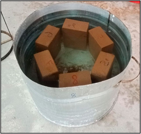
FIGURE 18. Absorption test.
2.5.4 Erosion test
The Australian Standard-Geelong drip test (Yttrup et al., 1981) can be used to determine the durability of CEBs. As illustrated in Figure 19, the block was put at a 45-degree angle, and 100 mL of water was dumped in the center of the 400 mm in height specimen during a 20–60-min period. The penetration depth was then measured, and the block was divided into two-halves to determine the depth of the water.

FIGURE 19. Geelong drip test.
2.5.5 Volume shrinkage test
According to the following equation, the volume shrinkage is equal to the volume change before and after drying, expressed as a percentage (Morel et al., 2007):
where Vο is the initial volume, and Vf is the final volume.
3 Results and discussion
3.1 Compressive strength and flexural strength
Three (300 mm × 150 mm × 108 mm) specimens were used for each mix in the compressive strength and flexural strength tests. These tests’ information and results are listed in Table 6 and Table 7 for compressive strength and flexural strength, respectively.

TABLE 6. Information and results for compressive strength test.
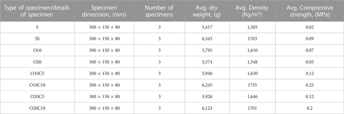
TABLE 7. Information and results for flexural strength test.
The addition of sand increased the strength by about 9% compared with the S mix in the compressive strength test (Figure 20) and about 77% in the flexural strength test (Figure 21). This is due to the shrinkage cracks that appeared immediately on the control samples after the compaction process. This result was expected because the particle size curve of the soil–sand mixes moved closer to the recommended grain size range for CEB production. The mechanical properties showed a decrease in strength upon adding OS as a single stabilizer. Consequently, replacing 10% of OS strength reduced the compressive strength and flexural strength by 31% (Figure 20) and 22% (Figure 21), respectively, compared with the SS mix. The compressive and flexural strength values were reduced by 45% in the O20 mix in comparison with the SS mix. Samples containing 10% OS and 5% cement (O10C5) revealed slight improvements in compressive and flexural strength by 2% (Figure 20) and 25% (Figure 21), respectively, compared to the SS mix. In addition, samples containing 10% OS and 10% cement (O10C10) revealed more improvements in compressive and flexural strength by 45% (Figure 20) and 64% (Figure 21), respectively, compared to the SS mix.
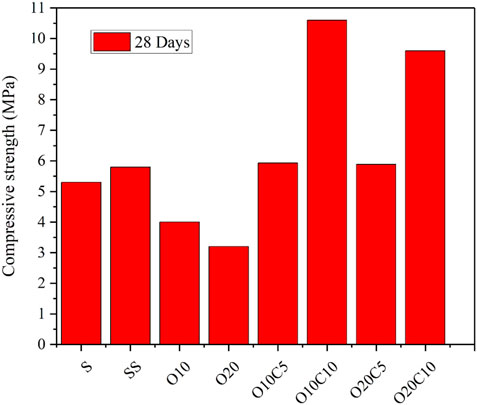
FIGURE 20. Compressive strength results of CEB.
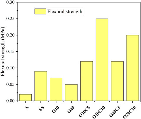
FIGURE 21. Flexural strength results of CEB.
In both tests, the compressive strength and flexural strength of the O20C5 mix were close to that of the O10C5. The addition of 20% OS and 10% cement improved compressive strength by about 40% up to 9.6 MPa (Figure 20) and flexural strength by about 55% up to 0.2 MPa in comparison to SS (Figure 21).
The best mix according to the flexural strength test was O10C10 (0.25 MPa) (Figure 21). It has been demonstrated, that in order to provide a minimum level of mechanical stability, the compressive strength of the CEB must be larger than 1.3 MPa (Cid-Falceto et al., 2012). As a result, the best mix according to the compressive strength test was the O10C10 mix (10.6 MPa) (Figure 20); this value is considered the highest compared to most of the previous research on CEB (Jaramillo-Pérez et al. (2014); Arsène et al., 2020; Edris et al., 2020; Edris et al., 2021). This could be explained by the active interaction between the silica in OS and the calcium hydroxide (Ca(OH)2) generated during the hydration of the cement, which results in the formation of calcium silicate hydrate and the subsequent development of a denser and stronger substance (Saidi and Hasan, 2020).
The dry density achieved after compaction is closely related to the compressive strength of the compressed Earth block. Within a block, compression reduces the number of voids and improves particle-to-particle contact. Figure 22 shows that as dry density increases, the compressive strength of individual blocks consistently increases.
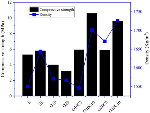
FIGURE 22. Realtion between compresive strength and density.
Table 8 and Figure 23 summarize various recent research on the compressive strength of compressed Earth block by using different stabilizers as a replacement for soil in compressed Earth block mixes. These studies have produced a variety of results, perhaps with some discrepancies. As a result, the findings from the present investigation will be presented alongside those from the studies indicated in Table 8 for comparison. In addition, Table 9 and Figure 24 illustrate the data obtained from numerous investigations about the influence of stabilizers on the flexural strength of CEB alongside the findings of the most recent study. It is seen that high flexural strength was obtained when any type of fiber was used.

TABLE 8. Various recent research on compressive strength of compressed Earth block.
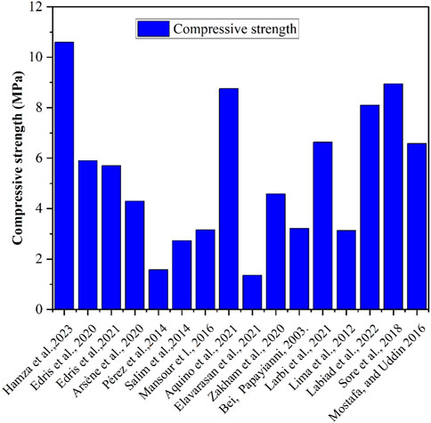
FIGURE 23. Comparison of present compressive strength with previous studies.
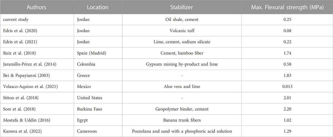
TABLE 9. Various recent research on flexural strength of compressed Earth block.

FIGURE 24. Comparison of present flexural strength with previous studies.
3.2 Absorption test
For each mix, three specimens (300 mm × 150 mm × 108 mm) were tested; the results are shown in Table 10. The S, SS, O10, and O20 mixes all failed in this test. The blocks were damaged immediately after being placed in the water. The O10C5 mix was tested and found to have a moisture content of 13.8%, whereas the O10C20 mix had a lower value of around 12.3%. The addition of 10% cement in the O10C10 and O20C20 mixes reduced moisture content by about 1.5% and 0.5% when comparing with O10C5 and O20C5, respectively.

TABLE 10. Absorption test results.
Figure 25 shows the absorption of the blocks increasing with the increment in the OS content. This could be due to nanopores’ structure on the OS particle, as both oil shale and diatomaceous Earth are organic sedimentary rocks, in addition to the high similarity in their chemical composition (Saidi and Hasan, 2020). The absorption of the O20C5 mix increased by about 0.7% compared with the O10C5 mix, and the moisture content of the O20C10 mix increased by about 1.4% compared with the O10C10 mix. As a result, the best sample in the absorption test with the least absorption percentage was the O10C10 mix, with 13.8% moisture content.

FIGURE 25. Water absorption results for all mixes.
Table 11 and Figure 26 summarize recent studies on compressed Earth block water absorption when using different stabilizing agents in place of soil in compressed Earth block mixtures. There may have been some inconsistencies in the results that this research obtained. Therefore, the results of the present research will be compared to those of the studies listed in Table 11 and Figure 26. In addition, as water absorption increased, the compressive strength decreased, as shown in Figure 27.
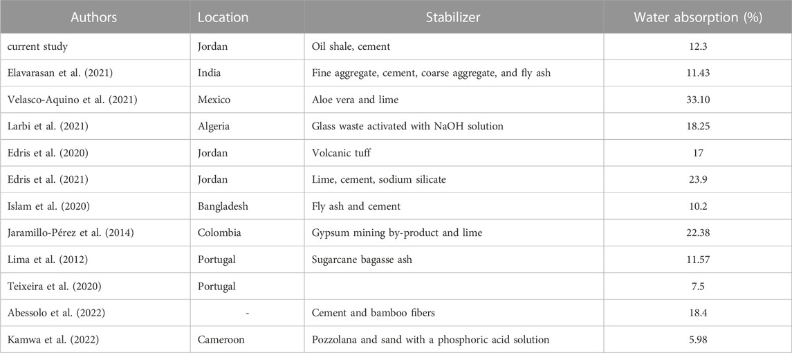
TABLE 11. Various recent research on water absorption of compressed Earth block.
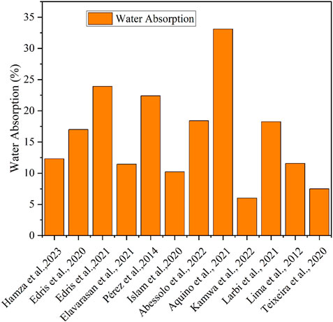
FIGURE 26. Comparison of present water absorption with previous studies.
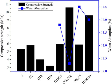
FIGURE 27. Realtion between compresive strength and water absorption.
3.3 Erosion test
The consequences of erosion are connected to absorption; as absorption increases, so do penetration and pitting depth. As shown in Table 12 and Figures 28A–H, specimen O10C10 exhibited high resistance to erosion, with less penetration and pitting depth compared to other specimens. The results of this test on the compressed Earth blocks with a dripping time fixed to 34 min are shown in Table 12. Figure 29 shows that compressed Earth blocks with zero pitting depth have a higher compressive strength.
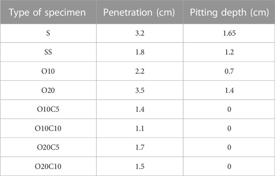
TABLE 12. Erosion test results.
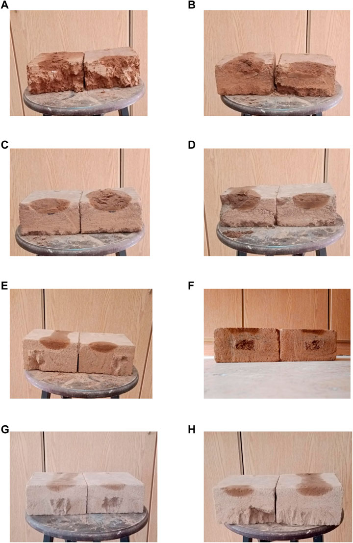
FIGURE 28. Erosion test result. (A) S mix, (B) SS mix, (C) O10 mix, (D) O20 mix, (E) O10C5 mix, (F) O10C10 mix, (G) O20C5 mix. (H) O20C10 mix.
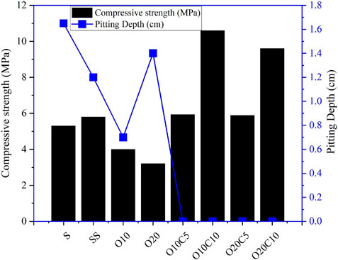
FIGURE 29. Realtion between compresive strength and pitting depth.
3.4 Shrinkage test
The control mixture (S mix) (Figure 31A) consisted of soil without any modification. It revealed weakness compared with the second mixture (SS mix) (Figure 31B), which means adding sand enhanced the mechanical properties. Additionally, the shrinkage properties of the OS sample were impacted by the presence of kaolinite. Due to the small interfoliar space, kaolinite crystals have few water molecules between their layers, and so when submerged in water, they only slightly swell in an intercrystalline manner (Arsène et al., 2020). Compared to smectite-type swelling clay, kaolinite sludge shrinks significantly less after drying (Tardy and Soler, 1993; Andrade et al., 2011). The soil sample containing swelling clay (smectite) had a higher drying shrinkage value than oil the shale samples that containing kaolinite, as shown in Figure 30. Although the addition of sand reduced the percentage of cracks, the addition of oil shale completely hid these cracks. Thus, the presence of oil shale in CEB has a clear and good effect on improving shrinkage properties (Figures 31C–H).

FIGURE 30. Volume drying shrinkage.
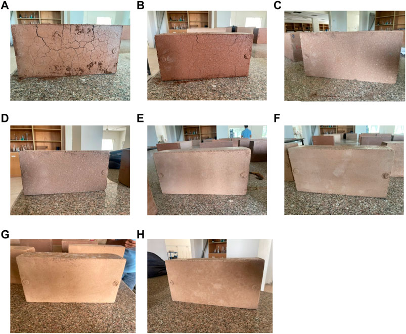
FIGURE 31. The difference between brick samples after kiln drying. (A) S mix, (B) SS mix, (C) O10 mix, (D) O20 mix, (E) O10C5 mix, (F) O10C10 mix, (G) O20C5 mix. (H) O20C10 mix.
4 Conclusion
The compressive strength, flexural strength, water absorption, erosion, and volume shrinkage test of CEB using ordinary Portland cement (OPC) and OS have been investigated. This study focused on the partial replacement of soil with cement and OS in eight mixtures at different replacement levels of 0%, 5%, 10%, and 20% based on weight. Meanwhile, 30% of sand was used in seven mixtures, thereby leading to the following:
• The local soil, without any additions, was revealed to be unsuitable for compressed Earth block manufacture due to the significant shrinkage cracks that occur immediately after the compaction process.
• The addition of 30% sand to clayey soil improved the compressive strength and flexural strength. This corresponds to the oncoming of the grain distribution of soil replaced by 30% sand to the recommended grain size range for CEB production.
• Regarding the mechanical properties, soil stabilized using 10% cement, and 10% OS had the highest value of compressive and flexural strengths of 10.6 and 0.25
• MPa, respectively. However, the compressive strength result was mechanically higher than the minimum mechanical stability for CEB.
• Regarding the durability properties, soil stabilized using 10% cement, and 10% OS had a lower water absorption percentage by 12.3, whereas soil without stabilization failed the test. The addition of 10% cement in the O10C10 and O20C20 mixes reduced water absorption by about 1.5% and 0.5% compared with O10C5 and O20C5, repetitively.
• Regarding the erosion test, the O10C10 mix exhibited high resistance to erosion, with less penetration and pitting depth compared to other specimens. The pitting depth value was zero for all mixes stabilized with different percentages of OS and cement.
• The use of oil shale as a stabilizing agent had a clear role in improving the shrinkage properties by completely hiding the shrinkage cracks and reducing the volumetric shrinkage value. The increase of OS as a soil replacement led to a slightly positive effect on the linear shrinkage percentage compared with the soil without stabilizing.
• The combination of the OS and cement as a stabilizer material was revealed to be appropriate, whereas a reduction was observed in the value of the water absorption, erosion, and linear shrinkage, as well as an increase in the value of the compressive and flexural strengths.
5 Recommendations
As a general recommendation for future research in favor of environmental and sustainability concerns, this study suggests the following:
• The resistance of Earth building substituted with OS to sulfates and salts should be investigated.
• It is a good idea to look into Earth building fire resistance. More research into the long-term effects of OS replacement on Earth building should be conducted.
• To determine cost/benefit analyses, a feasibility study is required.
• Research should be conducted on the effectiveness of OS in soil treatment with another type of soil.
Data availability statement
The original contributions presented in the study are included in the article/Supplementary Material, further inquiries can be directed to the corresponding author.
Author contributions
Conceptualization, MA-T and WE; methodology, HA and WE; formal analysis, HA-F and WE; data curation, HA-F, MA-T, and WE; writing—original draft preparation, HA-F and WE; writing—review and editing, MA-T and WE; supervision, MA and WE. All authors contributed to the article and approved the submitted version.
Acknowledgments
The authors are very grateful to Professor Antonio Zichichi for his financial support.
Conflict of interest
The authors declare that the research was conducted in the absence of any commercial or financial relationships that could be construed as a potential conflict of interest.
Publisher’s note
All claims expressed in this article are solely those of the authors and do not necessarily represent those of their affiliated organizations, or those of the publisher, the editors and the reviewers. Any product that may be evaluated in this article, or claim that may be made by its manufacturer, is not guaranteed or endorsed by the publisher.
Abbreviations
AASHTO, American Association of State Highway and Transportation Officials; CEB, Compressed Earth block; LL, Liquid limit; S, Mix with 100% soil; O20, Mix with 50% soil, sand content is 30% by weight, and oil shale is 20% by weight; O10, Mix with 60% soil, sand content is 30% by weight, and oil shale is 10% by weight; SS, Mix with 70% soil and sand content is 30% by weight; O20C10, Mix with soil content is 40% by weight, sand content is 30% by weight, oil shale is 20% by weight, and the cement content is 10% by weight; O20C5, Mix with soil content is 45% by weight, sand content is 30% by weight, oil shale is 20% by weight, and the cement content is 5% by weight; O10C10, Mix with soil content is 50% by weight, sand content is 30% by weight, oil shale is 10% by weight, and the cement content is 10% by weight; O10C5, Mix with soil content is 55% by weight, sand content is 30% by weight, oil shale is 10% by weight, and the cement content is 5% by weight; OS, Oil shale; OPC, Ordinary Portland cement; PL, Plastic limit; PI, Plasticity index; WSF, Wadi ShillalahShallala Formation; XRD, X-ray diffraction analysis; XRF, X-ray fluorescence.
References
Abessolo, D., Biwole, A. B., Fokwa, D., Ganou Koungang, B. M., and Baah, Y. B. (2022). Physical, mechanical and hygroscopic behaviour of compressed earth blocks stabilized with cement and reinforced with bamboo fibres. Int. J. Eng. Res. Afr. 59, 29–41. doi:10.4028/p-spbskv
AFNOR, X. (2001). Compressed Earth blocks for walls and partitions: Definitions-Specifications-Test Methods-Delivery acceptance conditions. Saint-Denis La Plaine Cedex. 91, 35.
Al-Otoom, A. Y. (2006). Utilization of oil shale in the production of Portland clinker. Cem. Concr. Compos. 28 (1), 3–11. doi:10.1016/j.cemconcomp.2005.06.006
Al-Tamimi, M. H., Alqudah, M., Al-Atawneh, M. S., Nazzal, J., and AlShraideh, S. (2021). Depositional environment of eocene oil shales of wadi Shillalah Formation from northern Jordan. Arabian J. Geosciences 14 (3), 209–219. doi:10.1007/s12517-021-06565-x
Alali, J., Abu Salah, A., Yasin, S. M., and Al Omari, W. (2015). Ministry of Energy and Mineral Resources, mineral status and future opportunity. Oil Shale, 1–23.
Andrade, F. A., Al-Qureshi, H. A., and Hotza, D. (2011). Measuring the plasticity of clays: A review. Appl. clay Sci. 51 (1-2), 1–7. doi:10.1016/j.clay.2010.10.028
Arsène, M. I. L., Frédéric, C., and Nathalie, F. (2020). Improvement of lifetime of compressed Earth blocks by adding limestone, sandstone and porphyry aggregates. J. Build. Eng. 29, 101155. doi:10.1016/j.jobe.2019.101155
ASTM (2019). Astm d6780/d6780m-19: Standard test methods for water content and density of soil in situ by time domain reflectometry (TDR).
ASTM. (2010). ASTM, D4318-10stardard test methods for liquid limit, plastic limit and plasticity index of soils, Conshohocken, Pa: Astm int. West.
Bei, G., and Papayianni, I. (2003). Compressive strength of compressed Earth block masonry. WIT Trans. Built Environ. 66. doi:10.2495/STR030371
Chaibeddra, S., and Kharchi, F. (2019). Performance of compressed stabilized Earth blocks in sulphated medium. J. Build. Eng. 25, 100814. doi:10.1016/j.jobe.2019.100814
Chen, W., Li, Y., Chen, S., and Zheng, C. (2020). Properties and economics evaluation of utilization of oil shale waste as an alternative environmentally-friendly building materials in pavement engineering. Constr. Build. Mater. 259, 119698. doi:10.1016/j.conbuildmat.2020.119698
Cid-Falceto, J., Mazarrón, F. R., and Cañas, I. (2012). Assessment of compressed Earth blocks made in Spain: International durability tests. Constr. Build. Mater. 37, 738–745. . doi:10.1016/j.conbuildmat.2012.08.019
Doat, P., Hays, A., Houben, H., Matuk, S., and Vitoux, F. (1979). Construire en terre. Éditions Alternative et parallèles.
Edris, W. F., Jaradat, Y., Al Azzam, A. O., Al Naji, H. M., and Abuzmero, S. A. (2020). Effect of volcanic tuff on the engineering properties of compressed Earth block. Archives Mater. Sci. Eng., 106 (1), 5, 16. doi:10.5604/01.3001.0014.5928
Edris, W., Matalkah, F., Sbaih, A. A., and Hailat, R. (2021). Characteristics of hollow compressed earth block stabilized using cement, lime, and sodium silicate. Civ. Environ. Eng., 17(1), 200–208. doi:10.2478/cee-2021-0021
El-Hasan, T., Abu-Jaber, N., and Abdelhadi, N. (2019). Hazardous toxic elements mobility in burned oil shale ash, and attempts to attain short-and long-term solidification. Oil Shale 36 (2S), 226–249. doi:10.3176/oil.2019.2S.12
Elavarasan, S., Priya, A. K., Gurusamy, R. R., Naveeth, J. M. R., and Natesh, S. (2021). Experimental study on compressed Earth block using fly-ash stabilizer. Mater. Today Proc. 37, 3597–3600. . doi:10.1016/j.matpr.2020.09.641
Fernandes, J., Peixoto, M., Mateus, R., and Gervásio, H. (2019). Life cycle analysis of environmental impacts of earthen materials in the Portuguese context: Rammed Earth and compressed Earth blocks. J. Clean. Prod. 241, 118286. doi:10.1016/j.jclepro.2019.118286
M. R. Hall, R. Lindsay, and M. Krayenhoff (Editors) (2012). “Modern Earth buildings,” Materials, engineering, constructions and applications (Amsterdam, Netherlands: Elsevier).
Houben, H., Guillaud, H., and Hall, B. B. (1994). Earth construction: A comprehensive guide. London: Intermediate Technology Publications, 362.
Islam, M. S., Elahi, T. E., Shahriar, A. R., and Mumtaz, N. (2020). Effectiveness of fly ash and cement for compressed stabilized Earth block construction. Constr. Build. Mater. 255, 119392. doi:10.1016/j.conbuildmat.2020.119392
Jaquin, P. (2012). “History of Earth building techniques,” in Modern earth buildings (Sawston, UK: Woodhead Publishing), 307–323. doi:10.1533/9780857096166.3.307
Jaramillo-Pérez, E. R., Plata-Chaves, J. M., and Ríos-Reyes, C. A. (2014). The use of gypsum mining by-product and lime on the engineering properties of compressed Earth blocks. Dyna 81 (188), 42–51. doi:10.15446/dyna.v81n188.39725
Jayasinghe, C., and Kamaladasa, N. (2007). Compressive strength characteristics of cement stabilized rammed Earth walls. Constr. Build. Mater. 21 (11), 1971–1976. doi:10.1016/j.conbuildmat.2006.05.049
Kamwa, R. A. T., Tome, S., Chongouang, J., Eguekeng, I., Spieß, A., Fetzer, M. N., et al. (2022). Stabilization of compressed Earth blocks (CEB) by pozzolana based phosphate geopolymer binder: Physico-mechanical and microstructural investigations. Clean. Mater., 4, 100062. doi:10.1016/j.clema.2022.100062
Labiad, Y., Meddah, A., and Beddar, M. (2022). Physical and mechanical behavior of cement-stabilized compressed Earth blocks reinforced by sisal fibers. Mater. Today Proc. 53, 139–143. doi:10.1016/j.matpr.2021.12.446
Larbi, S., Khaldi, A., Maherzi, W., and Abriak, N. E. (2021). Formulation of compressed Earth blocks stabilized by glass waste activated with naoh solution. Sustainability, 14(1), 102. doi:10.3390/su14010102
Lenci, S., Clementi, F., and Sadowski, T. (2012). Experimental determination of the fracture properties of unfired dry Earth. Eng. Fract. Mech. 87, 62–72. doi:10.1016/j.engfracmech.2012.03.005
Lima, S. A., Varum, H., Sales, A., and Neto, V. F. (2012). Analysis of the mechanical properties of compressed Earth block masonry using the sugarcane bagasse ash. Constr. Build. Mater. 35, 829–837. doi:10.1016/j.conbuildmat.2012.04.127
Mansour, M. B., Jelidi, A., Cherif, A. S., and Jabrallah, S. B. (2016). Optimizing thermal and mechanical performance of compressed Earth blocks (CEB). Constr. Build. Mater. 104, 44–51. doi:10.1016/j.conbuildmat.2015.12.024
Middleton, G. F., and Schneider, L. M. (1987). Bulletin 5, earth-wall construction. Chicago, Illinois: Sai global.
Morel, J. C., Pkla, A., and Walker, P. (2007). Compressive strength testing of compressed Earth blocks. Constr. Build. Mater. 21 (2), 303–309. doi:10.1016/j.conbuildmat.2005.08.021
Mostafa, M., and Uddin, N. (2016). Experimental analysis of Compressed Earth Block (CEB) with banana fibers resisting flexural and compression forces. Case Stud. Constr. Mater. 5, 53–63. doi:10.1016/j.cscm.2016.07.001
Nshimiyimana, P., Miraucourt, D., Messan, A., and Courard, L. (2018). Calcium carbide residue and rice husk ash for improving the compressive strength of compressed Earth blocks. MRS Adv. 3, 2009–2014. doi:10.1557/adv.2018.147
Paaver, P., Paiste, P., Liira, M., and Kirsimäe, K. (2019). Alkali activation of Estonian ca-rich oil shale ashes: A synthesis. Oil Shale 36 (2S), 214–225. doi:10.3176/oil.2019.2S.11
Reinhardt, H. W., and Grosse, C. U. (2004). Continuous monitoring of setting and hardening of mortar and concrete. Constr. Build. Mater. 18 (3), 145–154. doi:10.1016/j.conbuildmat.2003.10.002
Ruiz, G., Zhang, X., Edris, W. F., Cañas, I., and Garijo, L. (2018). A comprehensive study of mechanical properties of compressed Earth blocks. Constr. Build. Mater. 176, 566–572. doi:10.1016/j.conbuildmat.2018.05.077
Saidi, M., Cherif, A. S., Zeghmati, B., and Sediki, E. (2018). Stabilization effects on the thermal conductivity and sorption behavior of Earth bricks. Constr. Build. Mater. 167, 566–577. doi:10.1016/j.conbuildmat.2018.02.063
Saidi, T., and Hasan, M. (2020). The effect of partial replacement of cement with diatomaceous Earth (DE) on the compressive strength and absorption of mortar. J. King Saud University-Engineering Sci. 34 (4), 250–259. doi:10.1016/j.jksues.2020.10.003
Salim, R. W., Ndambuki, J. M., and Adedokun, D. A. (2014). Improving the bearing strength of sandy loam soil compressed Earth block bricks using sugercane bagasse ash. Sustainability, 6(6), 3686–3696. doi:10.3390/su6063686
Sitton, J. D., Zeinali, Y., Heidarian, W. H., and Story, B. A. (2018). Effect of mix design on compressed Earth block strength. Constr. Build. Mater. 158, 124–131. doi:10.1016/j.conbuildmat.2017.10.005
Sore, S. O., Messan, A., Prud'Homme, E., Escadeillas, G., and Tsobnang, F. (2018). Stabilization of compressed Earth blocks (CEBs) by geopolymer binder based on local materials from Burkina Faso. Constr. Build. Mater. 165, 333–345. doi:10.1016/j.conbuildmat.2018.01.051
Taallah, B., Guettala, A., Guettala, S., and Kriker, A. (2014). Mechanical properties and hygroscopicity behavior of compressed Earth block filled by date palm fibers. Constr. Build. Mater. 59, 161–168. doi:10.1016/j.conbuildmat.2014.02.058
Tardy, Y., and Soler, J. M. (1993). Pétrologie des latérites et des sols tropicaux). Paris: Masson, 459.
Teixeira, E. R., Machado, G., P Junior, A. D., Guarnier, C., Fernandes, J., Silva, S. M., et al. (2020). Mechanical and thermal performance characterisation of compressed earth blocks. Energies 13 (11), 2978. doi:10.3390/en13112978
UNE 41410 (2008). UNE 41410 Bloques de tierra comprimida para muros y tabiques. Defin. especificaciones métodos Ens. 28. https://www.en-standard.eu/une-41410-2008-compressed-earth-blocs-for-walls-and-partitions-definitions-specifications-and-test-methods/
Velasco-Aquino, A. A., Espuna-Mujica, J. A., Perez-Sanchez, J. F., Zuñiga-Leal, C., Palacio-Perez, A., and Suarez-Dominguez, E. J. (2021). Compressed Earth block reinforced with coconut fibers and stabilized with aloe vera and lime. J. Eng. Des. Technol. 19 (3), 795–807. doi:10.1108/JEDT-02-2020-0055
Venkatarama Reddy, B. V., and Prasanna Kumar, P. (2011). Cement stabilised rammed Earth. Part A: Compaction characteristics and physical properties of compacted cement stabilised soils. Mater. Struct. 44 (3), 681–693. doi:10.1617/s11527-010-9658-9
Wei, H., Zhang, Y., Cui, J., Han, L., and Li, Z. (2019). Engineering and environmental evaluation of silty clay modified by waste fly ash and oil shale ash as a road subgrade material. Constr. Build. Mater. 196, 204–213. doi:10.1016/j.conbuildmat.2018.11.060
Yihdego, Y., Salem, H. S., Kafui, B. G., and Veljkovic, Z. (2018). Economic geology value of oil shale deposits: Ethiopia (tigray) and Jordan. Energy Sources, Part A Recovery, Util. Environ. Eff. 40 (17), 2079–2096. doi:10.1080/15567036.2018.1488015
Yttrup, P. J., Diviny, K., and Sottile, F. (1981). Development of a drip test for the erodability of mud bricks. Geelong, Australia: Deakin University, School of Architecture.
Keywords: Earth building, Jordanian oil shale, CEB, stabilization, cement
Citation: Al-Fhaid H, Edris WF and Al-Tamimi M (2023) Potential utilization of oil shale as a stabilizing material for compressed Earth block. Front. Built Environ. 9:1199744. doi: 10.3389/fbuil.2023.1199744
Received: 03 April 2023; Accepted: 12 June 2023;
Published: 22 June 2023.
Edited by:
Bjorn Birgisson, University of Georgia, United StatesCopyright © 2023 Al-Fhaid, Edris and Al-Tamimi. This is an open-access article distributed under the terms of the Creative Commons Attribution License (CC BY). The use, distribution or reproduction in other forums is permitted, provided the original author(s) and the copyright owner(s) are credited and that the original publication in this journal is cited, in accordance with accepted academic practice. No use, distribution or reproduction is permitted which does not comply with these terms.
*Correspondence: Walid Fouad Edris, d2FsaWQuZWRyaXNAeXUuZWR1Lmpv