 Patrick Urassa
 Haileleoul Sahle Habte2
- 1Department of Mechanical and Industrial Engineering, Norwegian University of Science and Technology, Trondheim, Norway
- 2Addis Ababa Institute of Technology, Addis Ababa University, Addis Ababa, Ethiopia
Rail transportation is a pivotal mode of land transport for its efficiency in transporting passengers and freight across short or long distances; hence, the reliability and safety of rail systems are of key importance. Rolling contact fatigue (RCF), characterized by the cyclic loading of wheel-rail contacts, presents a significant challenge in the rail industry. This study presents a comprehensive numerical investigation on the influence of different crack orientations on the contact stress of the rail profile and subsequently the fatigue life. Using finite element analysis (FEA) with Abaqus and FE-safe software, the study examined different crack orientations’ impact on stress distribution and fatigue life of rail profiles. Employing the extended finite element method (XFEM), this study modeled cracks in rail profiles with different orientations: parallel, perpendicular, and oblique to the rail axis. finite element analysis was used to obtain stress distribution results, highlighting the impact of crack presence, and orientation on maximum contact stresses. Subsequently, fatigue analysis was performed using FE-safe software, wherein the FEA results were imported to estimate fatigue life and damage evolution. The study revealed that the presence of a crack significantly influences contact stress, fatigue life, and damage accumulation. The results further demonstrated that crack orientation has an impact on the severity of those effects. Oblique cracks exhibited higher impact compared to lateral and longitudinal cracks. The study provides valuable insights into rolling contact fatigue-related failures, aiding in better understanding and mitigation of such issues, thereby contributing to improved rail maintenance practices and system safety.
1 Introduction
Rail transport is a land transport in which the vehicles run on guided tracks known as rails. It is one of the most important modes of transport and very cost-effective in terms of transporting passengers and freight over long and short distances. Rail transportation has emerged as one of the most dependable modes of transport in terms of safety also; it has fixed routes and schedules, and its services are more certain, uniform, and reliable compared to other modes of land transport (Saakian and Savchuk, 2013). The railway system operates on metal rails and wheels; hence, it has less frictional resistance and thus consumes less energy which promotes railway transport system to be considered as an environmentally friendly and cost-effective mode of transport.
In the railway industry, especially in the tribological area (wheel-rail contact), fatigue failure is critical due to the repetitive action of wheels and rails sliding over each other. The wheel-rail contact generates extreme stresses in the contacting bodies because the contact area is very small compared to the overall dimension of the rail vehicle; thus, rolling contact fatigue is likely to occur. Research in railway vehicles (Bhaduri and Bhaduri, 2018; Zu et al., 2023) shows 50%–90% of mechanical failures are due to fatigue. Initially, wear and plastic deformation of rails were considered the major cause of failure. However, some measures were taken to counteract those problems to improve performance; the introduction of improved wheel-rail profiles, materials more resistive to wear, and the application of lubrication in the contact area are a few worth mentioning. As a result, wear and plastic deformation failure modes have been suppressed (Ringsber and Josefson, 2001; Sadeghi et al., 2009; Zerbst et al., 2009; Jaifu et al., 2018).
1.1 Rolling contact fatigue implications and maintenance strategies
Rolling contact fatigue (RCF) is the phenomenon that occurs in mechanical components involving rolling or sliding contacts in railway vehicles. RCF caused by applying cyclic loads on the components potentially lead to fatigue damage. Defects like squats, head checks, and shelling may cause the spalling of the rail, which affects the ride comfort and generates noise. Although the impact may not be immediately evident while the rail is still in operation, the cracks can spread and eventually lead to a complete fracture, which could cause a derailment (Kumar, 2006). Factors such as rail curve radius, axle load, stiffness of suspension system, rail-wheel profiles, traction and braking forces, and wheel/rail material properties affect RCF (Evans and Iwnicki, 2002; Thakkar et al., 2006). Examples of catastrophic damage observed related to rail failure due to RCF are the Seemanchal Express derailment that occurred on 3 February 2019 in India, the Hatfield derailment in the UK that occurred in 2000, the Columbus and Eliot city derailments in Ohio and Maryland, respectively, in the US in 2012 (Magel, 2011; Magel et al., 2016; Martua et al., 2018), the Bates derailment in South Australia in 2007, the Gainford derailment in Alberta, Canada, in 2013, and the Storsund–Koler derailment in Sweden in 2013 (Magel et al., 2016).
To minimize crack propagation, the railway maintenance departments adopt the practice of removing small railhead cracks (cracks at their very initial stage) by rail reprofiling and grinding on the railhead (Zhang et al., 2023). This process removes plastically deformed material on the railhead, which causes step marking known as slip bands. Accumulation of slip bands on the rail causes small cracks; thus, the rail reprofiling and grinding process reduce the possibility of crack initiation (Tehrani and Saket, 2009; Sangid, 2013). Nevertheless, for deeply developed cracks, the rail reprofiling and grinding processes are expensive and time-consuming, and as a result the railhead becomes thin, thus, the methods become inadequate. Rail failure due to cracks can potentially result in the derailment of railway vehicles. Such derailments have significant impacts on both human life and the environment (Magel, 2011; Martua et al., 2018). This study explores how crack orientations affect wheel/rail contact stress and, consequently, fatigue life.
1.2 Previous studies on wheel-rail interactions
In 2017, Garcia et al. carried out a study about wheel-rail and wheel-roller interaction using a test rig. Their objectives were to determine the Hertzian contact stress, the maximum contact pressure distribution, and the maximum von Mises stress. By implementing analytical and numerical methods, the research indicated that targeting the same objectives yields consistent results, whether adopting the Hertz or the elastic FE method for contact models (García-Prada et al., 2016).
Similarly, the study conducted by (Tehrani and Saket, 2009) follow the elastic-plastic FE method. Their study objective was to predict the fatigue life initiation due to high-cycle load. Stress analysis was performed, and fatigue damage in rails was evaluated numerically using the multiaxial fatigue crack initiation model. The effects of material hardness, material fatigue properties, vertical loading, and wheel/rail contact on fatigue crack initiation life were investigated by using stress history during one loading cycle and a fatigue damage model. The researchers suggested that future work needs to take into consideration the interactive effects of those parameters because the wheel/rail contact problem is highly non-linear.
In 2017, El-Sayed et al. performed a numerical simulation to study fatigue crack initiation life in railheads. The study focused on the growing issue of RCF, particularly addressing aspects that had been overlooked in prior research; they took into consideration bending stresses due to the global dynamic response of railway tracks and local stresses due to wheel-rail contact loads. Finite Element (FE) analysis results were integrated with the critical plane method and multiaxial low-cycle fatigue model to predict crack orientation and and fatigue crack initiation life (El-sayed et al., 2018). They concluded that, the model realistically simulates wheel-rail contact, material non-linearity, and dynamic cyclic responses. In 2019, Zhang and Ren (2019) investigated the typical failure mode of high-speed railway wheels considering the failure of wheel grade ER8. Their study discussed wheel damage characteristics and failure types; internal rim cracks, tread shelling, and tread pressing injuries (Zhang and Ren, 2019). Additionally, In 2003, Cannon et al., identified and discussed the failure of rails in rail transport associated with rolling contact failure and the method of crack initiation, propagation, and fracture modeling for rail failure study (Cannon et al., 2003).
The study in (Josefson and Ringsberg, 2009) showed the risk of fatigue crack initiation and propagation in the railhead and rail web were accelerated by welding residual stress and uncertainty in load levels. They used finite element analysis to simulate the interaction between the welding residual stress field and stress field caused by service loads. The initiation of fatigue cracks was assessed using the shear-stress-based multi-axial fatigue criterion by Dang Van, and the propagation of fatigue cracks in the rail web was carried out using a Paris-type crack growth law. An assumption, based on random variables, was formulated where statistical analysis indicated that the contact load significantly impacts crack initiation and fatigue life. The welding residual stress magnitude came as the second most influencing parameter with respect to fatigue crack initiation. Jun et al., 2015 also studied crack failure analysis for weld-repaired rails which are more susceptible to crack initiation. The experimental and simulation on a weld-rail model showed that weld defects, lamella cracks, and abrupt change in the physical properties and internal structure of a material are potential causes for crack initiation on rails, and crack propagation is strongly influenced by tensile residual stress at the rail head due to the weld repair (Jun et al., 2016). Lo et al., 2010 also investigated the residual stress on failure for railway rails. The study considered new and used rails with different loading and service conditions, and their results revealed that due to wheel-rail contact loads, a hardened layer (tensile and compressive residual stress) developed on all used rails, while in new rail, the residual stress developed after load engagement. Further, their study identified severe grain deformation in rail gauge corners where a few small cracks initiated and propagated bigger-sized cracks (Lo et al., 2010).
Further, a study by Fedorko et al., 2020 studied unique rail damage that could be associated with hardened material indents on rail surfaces. The research model the small circular indent with linear center to center difference to form a cyclic damage. The study modeled the small circular indent with linear center to center difference to form a cyclic damage. The experimental study revealed that once the damage occured, progressive surface degradation leads to contact fatigue failure and horizontal crack formation that eventually leads to complete rail fracture (Fedorko et al., 2020).
Zhuo et al., 2023 investigated wheel-rail rolling contact fatigue, emphasizing the need to understand crack growth mechanisms due to their significant impact on railway safety and maintenance. The study employed a combination of theoretical models to simulate the conditions leading to fatigue crack growth and a finite element method to analyze stress distribution and crack propagation. The study discovered that crack growth is most critical when contact loads are applied and identified factors that can intensify the growth. Furthermore, the study provided new insights into the behavior of fatigue cracks under various mechanical loads and frictional conditions. This offers valuable information for improving the maintenance and safety of wheel-rail systems (Zhou et al., 2023).
1.3 Novelty of the study
It is evident from the research above that rolling contact fatigue affects rail profiles, and previous studies have focused on notches, weld residuals, and grain boundaries as initial areas for crack formation in their finite element analyses; this study utilizes the extended finite element method (XFEM) to model crack initiation. To the authors’ knowledge, research work that investigates the influence of different crack orientations in the contact stress of the rail is limited. In this study, the influence of different crack orientations, parallel (longitudinal), perpendicular (lateral), and oblique on the contact stress, was investigated. The extended finite element method (XFEM) was adapted to model cracks in the rails for finite element analysis, and subsequent fatigue analysis was used to assess their impact on the life of rail profiles.
2 Material and methods
The influence of cracks in the fatigue life of the rail was analyzed using FEM. In this analysis, the following methods were applied as depicted in the Figure 1.
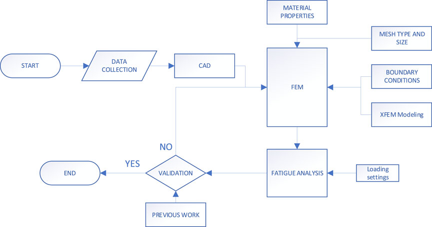
FIGURE 1. Methodology flowchart.
2.1 Data collection
To develop the geometrical models, the international standard model configuration BS EN 13262:2020 and BS EN 13674 for the rail and wheel, respectively, were considered. Table 1 depicts the mechanical properties of the wheel and rail, and Table 2 lists the axle load adopted for this study.
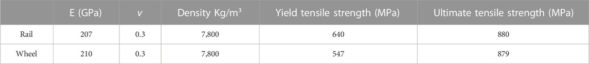
TABLE 1. Wheel and Rail mechanical properties (iTeh Standards, 2020).
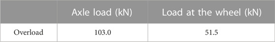
TABLE 2. Axle load.
2.2 Mathematical modeling
Research on the wheel/rail interface can be done experimentally or numerically. However, experimental approaches have many difficulties, and it is expensive. On the contrary, the numerical technique has proven to be a useful and alternative tool for complicated and expensive simulations. The model setup and boundary conditions are modeled in such a way that they are near to the real settings. That being said, the finite element method (FEM) was chosen for this research work.
2.2.1 Governing equations
The assumptions of Hertzian contact theory provide the theoretical foundation for wheel/rail contact. In the wheel/rail interface, the contact area and pressure distribution can be computed by using Hertz contact theory. When two elastic non-conforming objects are pressed together, the contact region takes on an oval shape with a semi-major axis ‘a' and a semi-minor axis ‘b' (Srivastava et al., 2014). The contact pressure distribution depicted in Figure 2 is a semi-ellipsoid, expressed as:
where
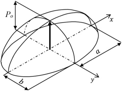
FIGURE 2. Pressure distribution across an elliptic area (Shin and Hur, 2022).
2.2.2 Contact stress in the wheel/rail interaction by applying Hertz theory
Considering the material models for a pair of contact bodies are linear-elastic, with friction between the contacting surfaces, the material data
The angle
Where
The coefficients ‘m' and ‘n' connect the ellipticity parameter
The ‘m’ and ‘n’ values are obtained on the Hertzian contact-stress coefficients by interpolation, thus, the values corresponding to
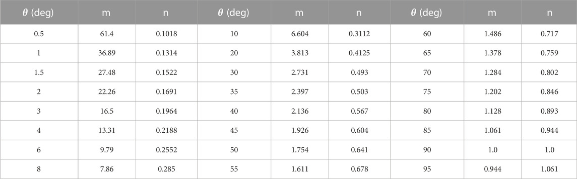
TABLE 3. Coefficients for Hertz’s theory (Cooper, 1968).
From interpolation, the value of ‘m’ and ‘n’ corresponding to
The
According to Hertz’s contact theory, the highest principal stress at the point of contact is perpendicular to the plane of the contact point, which is on the line of applied load, and this applied load might be compressive or tensile (Yan and Fischer, 2000).
Thus, the maximum pressure at the contact point will be as follows:
And the average contact pressure,
The average pressure obtained using Hertz contact theory will be valuable input in the validation section of this study. The pressure will be compared with the contact pressure obtained in the published research work.
2.3 Finite element formulation procedure in Abaqus/CAE
In this stage, the model of the physical problem was defined, and an ABAQUS input file was created. The 3D model was created by AutoCAD 2018 for adequate CAD modeling that imitates the real wheel and rail profiles, see Figure 3, and then imported to the simulation software.
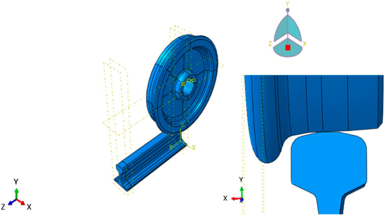
FIGURE 3. Model assembly and wheel/rail interface.
2.3.1 Analysis steps
In this model, a one-step analysis was defined. This step provides a convenient way to capture changes in the loading and boundary conditions of the model and changes in the way parts of the model interact with each other. In addition, the step allows for the changing of the analysis procedure, the data output, and various controls. The step analysis selected was general static with 1,000 increments. The static, general analysis step was selected due to its compatibility with modeling the extended finite element method (XFEM) crack (Sukumar and Prévost, 2003; Fries and Baydoun, 2012).
2.3.2 Material modeling
Material modeling considers the wheel and rail mechanical properties as depicted in the FEM based on Table 1. Also, the rail plastic deformation was taken into consideration, since when the rail material reached its elastic limit, further application of stress will result in permanent deformation. After yielding, when the load is removed from the rail, not all the strain-affected material recovers its initial state; this condition is caused by the rearrangement of the atoms within a material, and it is irreversible. When the load is removed, the plastic deformation remains in the material as permanent, non-recoverable deformation (Abramowitch and Easley, 2016). Plastic deformation is considered as piecewise linear with applied stresses, refer to Table 4 for the values of plastic strain which used as input parameter in rail material property in Abaqus.
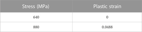
TABLE 4. Plastic strain.
2.3.3 Interaction
The interaction module gives a variety of options. Based on the model, focuses were directed to some special interaction parameters: contact, crack, and constraints. The contact definition was defined using the contact property tool. Initially, mechanical tangential behavior was defined using a penalty friction formulation with friction coefficient of 0.35 (Harmon et al., 2020), followed by normal behavior with hard contact in Abaqus. The nature of contact used for this study was surface-to-surface contact, and the contact pairs were defined as the wheel circumference (master surface) and the top of the rail surface (slave surface) (Yang et al., 2019).
2.3.4 Element type and mesh convergence
The model was meshed using three-dimensional, linear hexahedral geometric order elements and eight-node solid elements with uniform reduced integration (C3D8R). Uniform reduced integration enhanced the efficiency of model simulation by reducing the computational cost through hourglass control (Pagani et al., 2014). To have an adequate simulation result, mesh refinement is needed. Using a coarse mesh size yields an incorrect result; therefore, enhancing the mesh density to a very fine level helps the solution converge to more precise values. However, this improvement in accuracy significantly increase the computational time and cost (Baiges et al., 2020). Mesh convergence helps to conclude that the model used for the simulation gives a valid result, and it can be done by using different parameters like stress, energy, pressure, and strain. To find convergence, different mesh sizes were used in the model, and the analysis result showed that the maximum stress (von Mises) starts to converge at an element size of 9 mm, see Figure 4. For this study, a global mesh size of 7 mm was adequate for the simulation. Further decreasing the mesh size will only increase the computational time/cost with a minor effect on the desired results. Using this value, the wheel/rail model was created with a mesh consisting of 48,857 nodes and 39,546 elements.
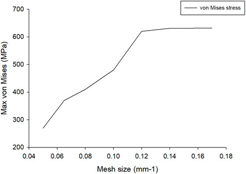
FIGURE 4. Mesh convergence (mesh size vs. von Mises).
2.3.5 Boundary conditions
The boundary conditions adopted were essential boundary conditions (e.g., velocity constraints) and natural boundary conditions (e.g., vertical force). The velocity and displacement were defined on the wheel reference point (center of the wheel) to move along the rail’s axis. The velocity assigned was 11,666 mm/s (El-sayed et al., 2018; Jaifu et al., 2018) and the wheel displacement was defined as 600 mm, which is the distance between two sleepers and it is quite enough to learn the dynamic response of the rail due to bending. Having a shorter rail enables the model to have a very fine mesh with a significant reduction in computational time/cost (Mathias and Kim, 2019; Baiges et al., 2020).
2.3.6 XFEM crack modeling
The surface crack was modeled in three different orientations, parallel, perpendicular, and at an angle from the rail’s axis, by using the XFEM interface. Their different orientations were targeted for this study to represent the real conditions of RCF cracks identified from field observations and the literature (Franklin and Kapoor, 2007; Goswami, 2019). For the longitudinal (parallel to rail’s axis) crack, since the crack was observed near the gauge corner, the propagation was thus predicted to propagate through the rail head’s lower jaw. Likewise, the lateral and oblique cracks (perpendicular and at an angle from the rail’s axis) were modeled in same region as that of the longitudinal crack (Rajagopal et al., 2018). All cracks were modeled with an equal length of 16 mm.
2.3.7 Crack initiation and propagation
Crack initiation refers to the beginning of degradation of the cohesive forces within the element and especially at an enriched element, and this degradation occurs in the area with local discontinuities like notches, grain boundaries, welds residual, and modeled XFEM cracks (Areias and Belytschko, 2005; Bergara et al., 2017).
In this study, the maximum principal stress damage criterion (Maxps Damage) was considered in the crack definition. The maximum principal stress was considered because it is the main failure criterion that is widely used in recent times for predicting failure of ductile materials (Feng et al., 2019). Also, the maximum principal stress theory is suitable for promising the safe design of machine components made of ductile materials under the three conditions: a uniaxial state of stress, biaxial state of stress, and hydrostatic stress (Bansal, 2009).
The maximum principal stress damage criterion is represented as
The crack is initiated once the ‘f’ in Eq. 12 exceeds 1. Thus, to avoid crack initiation in the rail, the allowable working stress must be less than 640 MPa which would be lower than the maximum stress (yield stress).
where.
•
• The brackets ⟨⟩ represent the Macaulay bracket,
i.e.,
The Macaulay brackets signify that a purely compressive stress state does not initiate damage. Damage is assumed to initiate when the maximum stress exceeds the critical stress, when the ratio of maximum principal stress to maximum allowable principal stress reaches a value of 1 (Smith et al., 2014; Mohamed et al., 2016).
2.3.8 Damage evolution
The damage evolution law for steel structures describes the rate at which the cohesive stiffness of a material is degraded after the corresponding crack initiation criterion is reached (Al-Himairee et al., 2011). A scalar damage variable, D, represents the overall damage at the intersection between the crack surfaces and the edges of cracked elements (Chen et al., 2019). Initially, before the damage has been modeled, the value is 0; after damage evolution is modeled, D evolves from 0 to 1 upon further loading after damage initiation (Al-Himairee et al., 2011; Chen et al., 2019; Fu and Rivera-Díaz-del-Castillo, 2022). The general framework for damage evolution is found in the material properties editor of the corresponding material.
Effective separation of the evolution of damage under a combination of normal and shear separations across the interface is defined as
where.
Crack growth requires progressive damage, which includes softening of material and loss of stiffness which cause severe convergence difficulties. To counteract the convergence difficulties, damage stabilization must be introduced. It has to be within an acceptable limit because too much stabilization causes a negative influence on the solution and produces even non-physical results. The acceptable limit taken as the damage stabilization cohesive coefficient was 1e-06 (Singh et al., 2014).
Fracture energy was estimated using this relationship:
where GIC is the energy release rate, KIC is the fracture toughness of the rail material (48 MPa-m-0.5) (Godefroid et al., 2020), and E is the Young’s modulus of the rail material (207 GPa).
2.4 Fatigue analysis in FE-safe
Fatigue analysis in FE-safe starts after importing the FEA file in the form of a dataset (e-strain, s-MPa, f-N, or D-mm) from the FEA tool and setting all needed parameters perfectly in the FE model platform in FE-safe. By starting fatigue analysis, the following procedures were employed.
2.4.1 Manage analysis group in the fatigue platform
Before starting to perform fatigue analysis, the analysis group on the FE-safe has to be selected and for that only the rail group was selected as the analysis group to proceed with the next stage of analysis. This supports the fatigue platform to give an option in the analysis group to assign the material and algorithm to be used.
2.4.2 Material definition and algorithm selection
In assigning material to be used in the analysis, FE-safe incorporates a fatigue platform and material database platform. The material database platform in FE-SAFE provides an option to tailor the material properties according to the specific requirements of the simulation. Following the selection of the rail material for analysis, the Brown–Miller criterion is designated as the algorithm to be employed.
Fe-Safe software’s Brown–Miller criterion with mean stress correction is the most realistic life estimate for ductile materials (STL, 2014). The Brown–Miller equation to determine the fatigue life is given by:
where.
b Fatigue strength exponent
c Fatigue ductility exponent.
3 Results and discussion
3.1 Contact stress results from FEA
The stress results from different configurations of crack orientation in finite element analysis are illustrated. The analysis encompassed scenarios with a rail devoid of cracks and with cracks oriented in parallel, perpendicular, and at a 45° angle along the rail’s axis. This examination aimed to understand how different crack orientations influence the maximum stress experienced by the rail.
3.1.1 Rail devoid of cracks
In the absence of any defect or crack formation in the rail, the identified maximum Von Mises stress at a contact area was 633.1 MPa. As depicted in Figure 5A, this maximum stress value remained below the yield stress of the rail material, signifying minimal plastic deformation in the rail. Since the axle load used (51.5 kN) was considered as overloading carrying capacity, the proximity of the maximum stress to the yield strength thus implies that the overloading effects on the train are within allowable working stress.
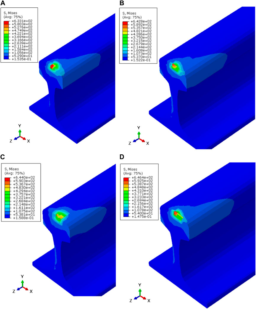
FIGURE 5. Maximum contact stress (MPa) of (A) a rail devoid of cracks and (B) a rail with a longitudinal crack, (C) lateral crack, and (D) oblique crack.
3.1.2 Longitudinal XFEM crack
When a longitudinal XFEM crack, aligned parallel to the rail’s axis near the rail gauge corner, was introduced, the maximum von Mises stress in the contact area increased to 642.8 MPa, as illustrated in Figure 5B. This increase in stress is attributed to the presence of the parallel XFEM crack and, notably, surpasses the yield strength of the rail material (640 MPa), resulting in plastic deformation.
3.1.3 Lateral XFEM crack
The modeling of a lateral XFEM crack, oriented perpendicular to the rail’s axis near the rail gauge corner, revealed that the maximum stress occurs in the vicinity of the crack. Figure 5C illustrates that the maximum von Mises stress recorded in the contact area for the rail with a lateral crack reached 644 MPa. Since these results exceed the yield stress, they lead to plastic deformation in the rail; also, the lateral crack’s impact is severer than the longitudinal crack.
3.1.4 Oblique XFEM crack
An oblique XFEM crack, situated at a 45° angle along the axis of the rail, had a pronounced impact on the rail compared to other crack orientations. The maximum von Mises stress for the rail with an oblique crack reached 646.4 MPa, as shown in Figure 5D. These results emphasize that the oblique crack orientation presents the severest stress conditions among all scenarios.
3.2 PEEQ results (equivalent plastic strain result)
The PEEQ represent the material’s inelastic deformation. If this variable is greater than zero, it implies the material has yielded. The PEEQ values become greater than zero at the vicinity of cracks. As demonstrated in Figure 6, the maximum observed PEEQ (1.799e-3) occurs in a rail with crack oriented at 45° from axial axis. In comparison, rails with cracks aligned either parallel or perpendicular to the axial axis show lower PEEQ values, specifically 5.486e-4 and 5.601e-4, respectively. This could be considered as the severest crack orientation that accelerates the crack propagation and decreases the service life.
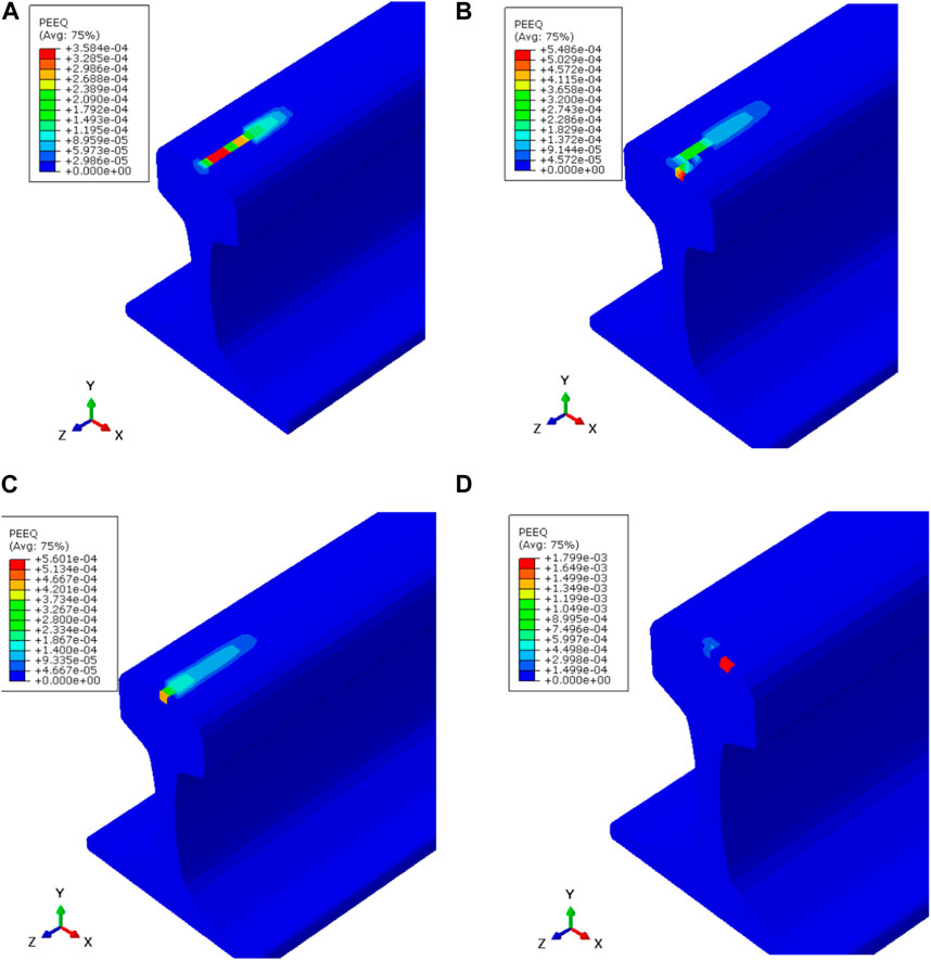
FIGURE 6. PEEQ results (A) without cracks (B), with a longitudinal crack, (C) a lateral crack, and (D) an oblique crack.
3.3 Results comparison
The maximum von Mises stress observed in wheel/rail contact using FEM (633.1 MPa) and maximum pressure using Hertz contact (947 MPa) in this study were in good agreement with the von Mises stress using FEM (614 MPa) and maximum pressure using Hertz contact (975 MPa) obtained in the article (García-Prada et al., 2016) by J. C. García-Prada et al., 2017 when using 50 kN see Figure 7.
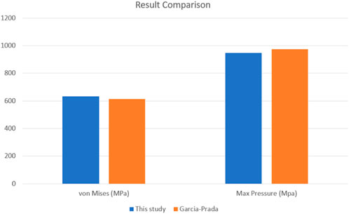
FIGURE 7. Results comparison chart.
3.4 Discussion
The summary of the study results are depicted in Table 5, and it has showed that, a rail without crack exhibits lower maximum von Mises stress, equivalent plastic strain and damage compared to rails with various cracks configuration. These findings imply that rails without cracks are more durable, potentially sustaining operations for over 1 million cycles ((>1M cycle). While among cases of rails with cracks, those with an orientation parallel to the rail’s axial axis showed less severity in stress, strain, and damage compared to rails with cracks oriented at 45° and 90° from the axial axis.
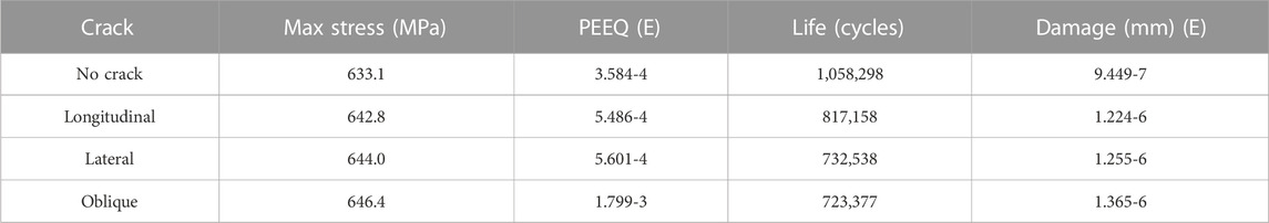
TABLE 5. Summary of results.
The study further identified that rails with cracks oriented at 45° experience a significantly reduced lifespan (32% less) and exhibit higher plastic strain and damage.Figure 8 illustrates that the fatigue life and damage of a rail changes abruptly once a defect or crack is initiated, in contrast to rails without defects or cracks. This abrupt change is attributed to the nature of the XFEM crack, which acts as a discontinuity, concentrating stress in a manner similar to other discontinuities such as notches and weld residues. The severity of a crack’s impact is also influenced by its orientation. Specifically, an oblique crack (oriented at 45° along the rail’s axis) results in a lower fatigue life cycle and higher damage compared to longitudinal and lateral cracks. This suggests that cracks not oriented parallel or perpendicular to the rail axis exert a higher crack propagation driving force.

FIGURE 8. The change in fatigue life and damage attributed to maximum von Mises stress.
4 Conclusion
In conclusion, the use of finite element analysis (FEA) and the extended finite element method (XFEM) in this study opens the door to further exploration of advanced simulation techniques, perhaps incorporating emerging technologies such as artificial intelligence and machine learning algorithms to predict fatigue life and crack propagation. Additionally, while numerical simulations are robust tools for theoretical analysis and offer valuable insights, they also come with inherent limitations. These simulations might not fully capture all the complexities and variabilities of the real world. Therefore, verifying these findings with real-world testing and field data could substantiate the results obtained from the simulation and significantly contribute to the body of knowledge in this area, making it a highly recommended direction for future research endeavors. To summarize, the study has revealed that.
• Cracks on rails significantly alter the stress distribution in rail profiles, leading to increasing plastic strain and damage compared with rails without cracks.
• The fatigue life for the rail is decreased significantly if the rail possess a surface crack.
• The orientation of cracks on the rail surface also affects the severity of stress induced in the rail and the resultant damage.
• Cracks oriented at 45° from the rail axial axis were observed to yield higher stress near crack surfaces that could accelerate crack propagation, consequently leading to complete fracture in short periods unless maintenance measures are conducted.
• The fatigue life of rails with cracks oriented along the rail axial axis and direction of ride has lower severity.
The implications of this research are of key importance in the railway industry, as it underscores the need for proactive crack detection and maintenance strategies on rails. Prioritizing the identification and remediation of cracks will enhance rail safety, extend operational life, and ensure the continued reliability of rail transportation. Ultimately, this study contributes valuable insights to the ongoing efforts to optimize rail maintenance practices and improve rail safety standards.
Data availability statement
The raw data supporting the conclusion of this article will be made available by the authors, without undue reservation.
Author contributions
PU: Conceptualization, Data curation, Methodology, Software, Visualization, Writing–original draft, Investigation. HH: Conceptualization, Supervision, Validation, Visualization, Writing–review and editing. AM: Conceptualization, Investigation, Software, Supervision, Validation, Writing–review and editing.
Funding
The author(s) declare that no financial support was received for the research, authorship, and/or publication of this article.
Conflict of interest
The authors declare that the research was conducted in the absence of any commercial or financial relationships that could be construed as a potential conflict of interest.
Publisher’s note
All claims expressed in this article are solely those of the authors and do not necessarily represent those of their affiliated organizations, or those of the publisher, the editors and the reviewers. Any product that may be evaluated in this article, or claim that may be made by its manufacturer, is not guaranteed or endorsed by the publisher.
References
Abramowitch, S., and Easley, D. (2016). “Introduction to classical mechanics,” in Biomechanics of the female pelvic floor (Amsterdam, Netherlands: Elsevier), 89–107.
Al-Himairee, R. M., Abed, F. H., and Al-Tamimi, A. K. (2011). Damage evolution in structural steel at different loading conditions. Key Eng. Mater. 471, 969–974. doi:10.4028/www.scientific.net/KEM.471-472.969
Areias, P. M., and Belytschko, T. (2005). Analysis of three-dimensional crack initiation and propagation using the extended finite element method. Int. J. Numer. methods Eng. 63 (5), 760–788. doi:10.1002/nme.1305
Baiges, J., Codina, R., Castanar, I., and Castillo, E. (2020). A finite element reduced-order model based on adaptive mesh refinement and artificial neural networks. Int. J. Numer. Methods Eng. 121 (4), 588–601. doi:10.1002/nme.6235
Bansal, R. K. (2009). “Principal stress and strain,” in Textbook of strength of materials (New Delhi, India: Laxmi Publisher), 85–138.
Bergara, A., Dorado, J., Martin-Meizoso, A., and Martínez-Esnaola, J. (2017). Fatigue crack propagation in complex stress fields: experiments and numerical simulations using the Extended Finite Element Method (XFEM). Int. J. Fatigue 103, 112–121. doi:10.1016/j.ijfatigue.2017.05.026
Bhaduri, A. (2018). “Fatigue,” in Mechanical properties and working of metals and alloys. Editor A. Bhaduri (Singapore: Springer Singapore), 317–371.
Cannon, D., Edel, K. O., Grassie, S., and Sawley, K. (2003). Rail defects: an overview. Fatigue and Fract. Eng. Mater. Struct. 26 (10), 865–886. doi:10.1046/j.1460-2695.2003.00693.x
Chen, X., Liu, J., Huang, X., Suo, T., and Li, Y. (2019). Numerical modeling of crack growth in polymer-bonded explosive with cavity subject to compression. Adv. Mech. Eng. 11 (6), 168781401985695. doi:10.1177/1687814019856954
Cooper, D. (1968), Tables of Hertzian contact-stress coefficients, Report no. R-387. Urbana, Illinois, United States: Coordinated Science Laboratory. Available: https://scholar.google.com/scholar?hl=en&as_sdt=0%2C5&q=D.+H.+Cooper%2C+%E2%80%9CTables+of+Hertzian+Contact-Stress+Coefficients&btnG=.
El-sayed, H., Lotfy, M., Zohny, H. E.-d., and Riad, H. (2018). Prediction of fatigue crack initiation life in railheads using finite element analysis. Ain Shams Eng. J. 9 (4), 2329–2342. doi:10.1016/j.asej.2017.06.003
Evans, J., and Iwnicki, S. D. (2002). “Vehicle dynamics and the wheel/rail interface,” in Wheels on Rails-an update: understanding and managing the wheel/rail interface (Manchester, United Kingdom: Rail Technology Unit). Available: https://e-space.mmu.ac.uk/11370/1/vehicle%20dynamics%20wheel%20rail%20interface.pdf.
Fedorko, G., Molnár, V., Blaho, P., Gašparík, J., and Zitrický, V. (2020). Failure analysis of cyclic damage to a railway rail–A case study. Eng. Fail. Anal. 116, 104732. doi:10.1016/j.engfailanal.2020.104732
Feng, N. L., Malingam, S. D., and Irulappasamy, S. (2019). Bolted joint behavior of hybrid composites. Fail. Analysis Biocomposites, Fibre-Reinforced Compos. Hybrid Compos., 79–95. doi:10.1016/B978-0-08-102293-1.00004-8
Franklin, F., and Kapoor, A. (2007). Modelling wear and crack initiation in rails. Proc. Institution Mech. Eng. Part F J. rail rapid transit 221 (1), 23–33. doi:10.1243/0954409JRRT60
Fries, T. P., and Baydoun, M. (2012). Crack propagation with the extended finite element method and a hybrid explicit–implicit crack description. Int. J. Numer. methods Eng. 89 (12), 1527–1558. doi:10.1002/nme.3299
Fu, H., and Rivera-Díaz-del-Castillo, P. E. (2022). Approaches to model structural and contact fatigue. Encycl. Mater. Metals Alloys, 576–588. doi:10.1016/B978-0-12-819726-4.00074-0
García-Prada, J. C., Castejón, C., Rubio, H., and Bustos, A. (2016). “Methodology to characterize the von Misses stress in the contact between wheel and rail (Test-Rig),” in 2016 18th International Wheelset Congress (IWC), Chengdu, China, November, 2016, 34–38. doi:10.1109/IWC.2016.8068363
Godefroid, L. B., Souza, A. T., and Pinto, M. A. (2020). Fracture toughness, fatigue crack resistance and wear resistance of two railroad steels. J. Mater. Res. Technol. 9 (5), 9588–9597. doi:10.1016/j.jmrt.2020.06.092
Goswami, L. (2019). Railway route crack detection system. Int. J. Innovative Technol. Explor. Eng. ISSN 2278, 3075. doi:10.35940/ijitee.l1043.10812s19
Harmon, M., Santa, J., Jaramillo, J., Toro, A., Beagles, A., and Lewis, R. (2020). Evaluation of the coefficient of friction of rail in the field and laboratory using several devices. Tribology-Materials, Surfaces Interfaces 14 (2), 119–129. doi:10.1080/17515831.2020.1712111
iTeh Standards, (2020). Railway applications: wheelsets and bogies wheels E. Norms. Available: https://standards.iteh.ai/catalog/standards/cen/7cc24f98-da4e-475c-bfa4-dc1b06c5af13/en-13262-2020.
Jaifu, A., Raeon, S., and Pimsarn, M. (2018). “Study of fatigue crack initiation location of wheel and rail under rolling contact using finite element method,” in MATEC web of conferences, Malang, Indonesia, August, 2018.02012.
Josefson, B. L., and Ringsberg, J. W. (2009). Assessment of uncertainties in life prediction of fatigue crack initiation and propagation in welded rails. Int. J. fatigue 31 (8-9), 1413–1421. doi:10.1016/j.ijfatigue.2009.03.024
Jun, H.-K., Seo, J.-W., Jeon, I.-S., Lee, S.-H., and Chang, Y.-S. (2016). Fracture and fatigue crack growth analyses on a weld-repaired railway rail. Eng. Fail. Anal. 59, 478–492. doi:10.1016/j.engfailanal.2015.11.014
Kumar, S. (2006). Study of rail breaks: associated risks and maintenance strategies. Available: https://www.diva-portal.org/smash/get/diva2:995250/FULLTEXT01.pdf.
Lo, K., Mummery, P., and Buttle, D. (2010). Characterisation of residual principal stresses and their implications on failure of railway rails. Eng. Fail. Anal. 17 (6), 1273–1284. doi:10.1016/j.engfailanal.2010.03.001
Magel, E., Mutton, P., Ekberg, A., and Kapoor, A. (2016). Rolling contact fatigue, wear and broken rail derailments. Wear 366, 249–257. doi:10.1016/j.wear.2016.06.009
Magel, E. E. (2011). Rolling contact fatigue: a comprehensive review. Available: https://rosap.ntl.bts.gov/view/dot/23669.
Martua, L., Ng, A. K., and Sun, G. (2018). “Prediction of rail rolling contact fatigue crack initiation life via three-dimensional finite element analysis,” in 2018 International Conference on intelligent rail Transportation (ICIRT), Singapore, December, 2018, 1–5.
Mathias, J., and Kim, D. H. (2019). Cost-effective, time-efficient passenger rail system for the eastern United States. J. Adv. Transp. 2019, 1–12. doi:10.1155/2019/4364162
Mohamed, S., Abdullah, S., Arifin, A., Ariffin, A., and Padzi, M. (2016). Characterization of the biaxial fatigue behaviour on medium carbon steel using the strain-life approach. Int. J. Automot. Mech. Eng. 13 (1), 3262–3277. doi:10.15282/ijame.13.1.2016.12.0272
Pagani, M., Reese, S., and Perego, U. (2014). Computationally efficient explicit nonlinear analyses using reduced integration-based solid-shell finite elements. Comput. Methods Appl. Mech. Eng. 268, 141–159. doi:10.1016/j.cma.2013.09.005
Rajagopal, M., Balasubramanian, M., and Palanivel, S. (2018). An efficient framework to detect cracks in rail tracks using neural network classifier. Comput. Sist. 22 (3), 943–952. doi:10.13053/CyS-22-3-3024
Ringsber, J., and Josefson, B. (2001). Finite element analyses of rolling contact fatigue crack initiation in railheads. Proc. Institution Mech. Eng. Part F J. Rail Rapid Transit 215 (4), 243–259. doi:10.1243/0954409011531558
Saakian, I., and Savchuk, V. (2013). Railway transportation: problems and solutions. Problems Econ. Transition 56 (3), 73–95. doi:10.2753/PET1061-1991560308
Sadeghi, F., Jalalahmadi, B., Slack, T. S., Raje, N., and Arakere, N. K. (2009). A review of rolling contact fatigue. J. Tribol. 131. doi:10.1115/1.3209132
Sangid, M. D. (2013). The physics of fatigue crack initiation. Int. J. fatigue 57, 58–72. doi:10.1016/j.ijfatigue.2012.10.009
Shin, G.-H., and Hur, J.-W. (2022). A new finite element analysis model to estimate contact stress in ball screw. Appl. Sci. 12 (9), 4713. doi:10.3390/app12094713
Singh, K. L., Keswani, K., and Vaggar, M. (2014). Crack growth simulation of stiffened fuselage panels using XFEM techniques. https://nopr.niscpr.res.in/handle/123456789/29417.
Smith, C. M., Deierlein, G. G., and Kanvinde, A. M. (2014). A stress-weighted damage model for ductile fracture initiation in structural steel under cyclic loading and generalized stress states. Tech. Rep. 187. Available: https://stacks.stanford.edu/file/druid:qy227tf3022/TR187_Smith.pdf.
Srivastava, J., Sarkar, P., and Ranjan, V. (2014). Contact stress analysis in wheel–rail by Hertzian method and finite element method. J. Institution Eng. (India) Ser. C 95, 319–325. doi:10.1007/s40032-014-0145-x
STL (2014). Fe-safe 6 fatigue theory reference manual. Available: http://www.3ds.com/products-services/simulia/products/fe-safe/.
Sukumar, N., and Prévost, J.-H. (2003). Modeling quasi-static crack growth with the extended finite element method Part I: computer implementation. Int. J. solids Struct. 40 (26), 7513–7537. doi:10.1016/j.ijsolstr.2003.08.002
Tehrani, P. H., and Saket, M. (2009). Fatigue crack initiation life prediction of railroad. J. Phys. Conf. Ser. 181 (1), 012038. doi:10.1088/1742-6596/181/1/012038
Thakkar, N. A., Steel, J. A., Reuben, R., Knabe, G., Dixon, D., and Shanks, R. (2006). Monitoring of rail-wheel interaction using acoustic emission (AE). Adv. Mater. Res. 13, 161–168. doi:10.4028/www.scientific.net/AMR.13-14.161
Yan, W., and Fischer, F. (2000). Applicability of the Hertz contact theory to rail-wheel contact problems. Archive Appl. Mech. 70, 255–268. doi:10.1007/s004199900035
Yang, Z., Deng, X., and Li, Z. (2019). Numerical modeling of dynamic frictional rolling contact with an explicit finite element method. Tribol. Int. 129, 214–231. doi:10.1016/j.triboint.2018.08.028
Zerbst, U., Lundén, R., Edel, K.-O., and Smith, R. A. (2009). Introduction to the damage tolerance behaviour of railway rails–a review. Eng. Fract. Mech. 76 (17), 2563–2601. doi:10.1016/j.engfracmech.2009.09.003
Zhang, G., and Ren, R. (2019). Study on typical failure forms and causes of high-speed railway wheels. Eng. Fail. Anal. 105, 1287–1295. doi:10.1016/j.engfailanal.2019.07.063
Zhang, S., Ding, H., Lin, Q., Liu, Q., Spiryagin, M., Wu, Q., et al. (2023). Experimental study on wheel-rail rolling contact fatigue damage starting from surface defects under various operational conditions. Tribol. Int. 181, 108324. doi:10.1016/j.triboint.2023.108324
Zhou, X., Li, S., Wang, J., Wang, K., and Jing, L. (2023). Fatigue crack growth in wheel-rail rolling-sliding contact: a perspective of elastic-plastic fracture mechanics criterion. Wear 530, 205069. doi:10.1016/j.wear.2023.205069
Keywords: contact stress, rolling contact fatigue, wheel/rail contact, cracks, XFEM
Citation: Urassa P, Habte HS and Mohammedseid A (2023) Crack influence and fatigue life assessment in rail profiles: a numerical study. Front. Built Environ. 9:1304557. doi: 10.3389/fbuil.2023.1304557
Received: 29 September 2023; Accepted: 21 November 2023;
Published: 18 December 2023.
Edited by:
Abdullah Ansari, Inha University, Republic of KoreaReviewed by:
Mahin Esmaeilzaei, Indian Institute of Technology Delhi, IndiaNarala Gangadhara Reddy, Fiji National University, Fiji
Ravi Kanth Sriwastav, Indian Institute of Technology Gandhinagar, India
Pawan Kumar Chamling, Indian Institute of Technology Kharagpur, India
Copyright © 2023 Urassa, Habte and Mohammedseid. This is an open-access article distributed under the terms of the Creative Commons Attribution License (CC BY). The use, distribution or reproduction in other forums is permitted, provided the original author(s) and the copyright owner(s) are credited and that the original publication in this journal is cited, in accordance with accepted academic practice. No use, distribution or reproduction is permitted which does not comply with these terms.
*Correspondence: Patrick Urassa, cGF0cmljay5lLnVyYXNzYUBudG51Lm5v