 Marcial Fernández-Castro
 Jean Truer
 Moises Espindola-Rodriguez
 Jens Wenzel Andreasen
- 1Department of Energy Conversion and Storage, Technical University of Denmark, Lyngby, Denmark
Organic Solar Cells (OSCs) have reached the highest efficiencies using lab-scale device manufacturing on active areas far below 0.1 cm2. The most used fabrication technique is spin-coating, which has poor potential for upscaling and substantial material waste. This tends to widen the so-called “lab-to-fab gap”, which is one of the most important challenges to make OSCs competitive. Other techniques such as blade or slot-die coating are much more suitable for roll-to-roll manufacturing, which is one of the advantages the technology presents due to the huge potential for fast and low-cost fabrication of flexible OSCs. However, only a few studies report solar cells using these fabrication techniques, especially applied on a roll-platform. Additionally, for environmentally friendly large area OSCs, inks based on non-hazardous solvent systems are needed. In this work, slot-die coating has been chosen to coat a PM6:Y6 active layer, using o-xylene, a more environmentally friendly alternative than halogenated solvents, and without additives. The optimal coating process is defined through fine-tuning of the coating parameters, such as the drying temperature and solution concentration. Moreover, ternary devices with PCBM, and fully printed devices are also fabricated. Power conversion efficiencies of 6.3% and 7.2% are achieved for binary PM6:Y6 and ternary PM6:Y6:PCBM devices measured with an aperture area of ∼0.4 cm2 (total device area ∼0.8 cm2).
Introduction
Higher efficiencies are continuously being reached in Organic Solar Cells (OSCs) especially due to the non-fullerene acceptors, which allow fine-tuning of their energy levels and light absorption with different donor materials (Liu et al., 2018; Li et al., 2019; Pang et al., 2020; Guo et al., 2021). Moreover, NFAs can reduce the VOC losses and present a stronger and wider visible-NIR absorption than fullerenes (Yan et al., 2018; Armin et al., 2021).
OSCs have interesting properties compared to other photovoltaic (PV) technologies, such as their low cost, their mechanical flexibility, their light weight, and the possibility of being semitransparent (Lucera et al., 2017; Zhang et al., 2019; Chen et al., 2020; Hu et al., 2020). OSCs are roll-to-roll compatible, which means they can be fabricated with high throughput and with very little energy investment, thus with a very short Energy Payback Time (EPBT) (Gertsen et al., 2019). The EPBT is the time needed to give back the energy used for manufacturing the device and can reach the order of days for organic photovoltaics (Espinosa et al., 2012).
Therefore, OSCs are one of the most promising PV technologies, driving a lot of research attention to achieve their industrialization. However, a large efficiency gap is still to be overcome between solar cells produced with lab-scale techniques (e.g. spin-coating) and the ones produced using industry-compatible processes. (Gertsen et al., 2019; Xue et al., 2021; Yang et al., 2021). The most reliable scalable fabrication techniques for OSCs are slot-die coating, blade-coating, or even spray/aerosol coating, due to their compatibility with roll-to-roll manufacturing. However, slot-die coating is preferred, as it is possible to coat with a one-dimensional pattern in the form of one or more stripes with a well-defined width and with almost no material waste (Søndergaard et al., 2012; Gertsen et al., 2019). Therefore, in order to contribute to minimizing the so-called “lab-to-fab gap” or “scalability lag”, slot-die coating should be the choice for further optimization.
A lot of new donors and acceptors appeared recently on the market, including PM6 donor and Y6 acceptor materials (chemical structures shown in Figure 1C). Excellent efficiencies over 15% were reported on rigid substrates when using hydrocarbon-based solvents (such as o-xylene) without additives, and in an inverted structure of glass/ITO/ZnO/PM6:Y6/MoO3/Al (Zhao et al., 2020). Other device structures were used with different transport layers and electrodes, achieving efficiencies between 10 and 16% (Guo et al., 2021). PM6 absorbance matches well the highest spectral irradiance point of the solar spectrum, whereas Y6 complements this absorption in the red part of the spectrum (Figure 1B). Several advances are being reported for larger area devices fabricated by slot-die coating in a roll-platform. Efficiencies above 12% were reported when using a ternary active layer based on PTB7-Th:COi8DFIC:PC71BM (Wang et al., 2020a). The negligible PCE scalability lag they obtained comparing slot-die with spin-coated devices was achieved thanks to a PET/silver-grid substrate with an incredibly low sheet-resistance, which led to a high FF in the final devices.
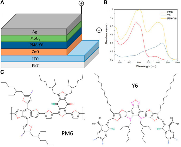
FIGURE 1. (A) Representation of the inverted OSC used for this study. (B) Absorbance of photoactive materials in o-xylene (16 mg/ml) slot-die coated at 100°C. (C) Molecular structures of PM6 and Y6.
When considering PM6:Y6:PCBM flexible large-area devices, efficiencies above 14% have been reported when using a spin-coated active layer in chloroform:chloronaphthalene and a blade-coated transparent electrode (Qin et al., 2021). Their transparent cathode was based on a silver grid coupled with silver nanowires and polyethylenimine-Zn with as HTL, and efficiencies between 14.3% (1 cm2) and 12.6% (10 cm2) were achieved. Modules with up to 54 cm2 based on 9-sub cells were also reported with efficiencies up to 13.2% (9.8% when considering geometry fill factor). Their work showcases the potential of PM6:Y6 as a high-performance candidate for flexible, large-area OSCs, even though the active layer was fabricated by non-scalable fabrication techniques. These two works show that improving the transparent electrode using alternatives with a lower sheet-resistance than ITO is a necessary step to decrease the scalability lag and the technology to succeed.
Therefore, the PM6:Y6 material combination is a good candidate to try and minimize the gap between efficiencies obtained using different manufacturing processes (Zhao et al., 2020; Guo et al., 2021; Liu et al., 2021; Würfel et al., 2021). To the best of our knowledge, there is still a need to transfer PM6:Y6-based devices to a roll-platform on flexible substrates, using scalable fabrication techniques while in open-air. PM6 exhibits temperature dependent aggregation (TDA) behavior and therefore needs to be heated to remain solubilized throughout the slot-die coating procedure (Zhao et al., 2020). In this case, the substrate, syringe, tube, and the slot-die head are heated during the coating according to the temperature-controlled slot-die coating procedure previously reported by our group (Fernández-Castro et al., 2022). In this work, we process OSCs using large-scale compatible processes on flexible lightweight substrates. We hope to contribute to the reduction of the “lab-to-fab gap” achieving higher efficiencies through scalable fabrication techniques, to finally bring this technology to the edge of commercialization (Gertsen et al., 2019; Xue et al., 2021). For the first time, slot-die coated flexible devices based on PM6:Y6 were fabricated in open-air, with efficiencies up to 7% when paired with fullerene acceptors in a ternary device. The best device reached a Fill Factor (FF) of nearly 50% and a high short-circuit current density (Jsc) of almost 20 mA/cm2 when coated at 100 °C. After more than 1,000 h of storage, the devices suffer almost no degradation.
Experimental
Materials
The materials involved in this study were purchased and used directly without further purification. The active layer materials, PM6 (batch YY19260CH100) and Y6 (batch DW7038S) were purchased from 1-Material Inc. whereas PB61BM (batch M111) was purchased from Ossila. The materials used for the transport layers are ZnO nanoparticle ink (from Sigma-Aldrich) and MoO3 pellets (from Kurt J. Lesker Co.). The flexible substrate is made of pre-patterned ITO-coated polyethylene terephthalate (PET), purchased from FOM Technologies. The silver used for the thermal evaporation of the back electrode is pure silver bought from Sigma-Aldrich. The solvent used in this study to prepare the active layer solution (ink) was o-xylene (with a ≥98% purity) and was purchased from Sigma-Aldrich.
Solar Cell Fabrication
As shown in Figure 1A, the device is made with the following inverted geometry: ITO/ZnO/PM6:Y6/MoO3/Ag. The ZnO Electron Transport Layer (ETL) and active layer are coated using a roll-coater, mimicking roll-to-roll conditions but at a laboratory scale.
A syringe pump is used to control the flow rate of the ink. The full setup is made with the capability to control the speed and heat of the drum and the drum-to-head distance. A heated-up tube is used to bring the ink from the syringe to the slot-die head at a controlled temperature.
The ZnO nanoparticle ink (ETL) was coated at a substrate temperature of 75°C with a 0.06 ml/min flow rate and a drum speed of 1.08 m/min. It is then annealed in an oven at 100°C for 10 min in air. The active layer PM6:Y6 (ratio 1:1) was coated at different temperatures (60, 80, 100, 120°C) and concentrations (12, 16, 20, 24, 28 mg/ml) for the study. The head, syringe, drum, and tube were kept at the same temperature, for each temperature under investigation, as in previous studies it was demonstrated this leads to an optimal performance (Na et al., 2019; Fernández Castro et al., 2020; Fernández-Castro et al., 2022). The drum speed was kept at 1.5 m/min and the solution was coated with a 0.12 ml/min flow rate. Finally, 10 nm of MoO3 as Hole Transport Layer (HTL) and 150 nm of Ag were thermally evaporated under vacuum at a base pressure of 2 × 10⁻⁵ mbar, through a shadow mask. The materials were sequentially evaporated from different tungsten boats. An INFICON XTM/2 system was used to monitor the deposition rate and thickness.
Before placing the devices in the evaporator, different parts of the 1-m-long active layer are selected to fabricate solar cells. Up to 24 solar cells are fabricated per evaporation. At least eight devices are then encapsulated. The devices have an approximate active area of 0.8 cm2.
Activation and Encapsulation
The cells are characterized directly after the evaporation of the back electrode. However, before encapsulation, a last step is necessary, an activation process that consists of a reverse bias current through the device (5 V/100 mA). This ensures the stabilization of the J-V curve before the encapsulation step. Encapsulation is made using an epoxy-based glue, EPXR, made of bisphenol A diglycidyl ether and Chissonox 221 monomers. Two glass slides are used to protect both up and down sides of the device where the EPOXY is applied, enabling the formation of an oxygen and humidity barrier once cured. Curing is made under UV light for approximately 5 min, with a temperature that reaches 66 ± 0.5°C during the process.
Characterization
The current density-voltage (J-V) curves were measured with a Keithley 2400 source meter (50 mV step reverse to forward) and a solar simulator, calibrated to 1000 W/m2 with a reference cell (monocrystalline silicon certified by Fraunhofer) under AM1.5G illumination. To ensure that the area is accurate and kept the same between different coatings, a shadow mask purchased from Ossila (E2002A1) was used to define an aperture area of 0.3996 cm2 (0.4 cm2 is written later for simplicity). Averages always include statistics of eight devices.
The External Quantum Efficiency (QE) and absorbance measurements are done with a QEX10 system (PV Measurements Inc.) from 300 to 1,100 nm (5 nm step size) calibrated with a Si photodiode.
The thickness measurements are done with a DS95-50 AFM instrument from the Danish Micro Engineering (DME). The dimension of the scans is a 5 × 5 μm2 surface while using the noncontact mode.
Results and Discussion
The optimization of the coating parameters of PM6:Y6-based devices using slot-die coating on a roll-platform is presented. All the slot-die coating steps were developed under ambient atmosphere. Therefore, our results can be easily transferred to an industrial roll-to-roll platform which is key to increasing the competitiveness of this technology (Gertsen et al., 2019), now that higher efficiencies are being reached using lab-scale techniques.
First, we present the optimization of the active layer studying the effect of both, coating temperature and active layer thickness on the performance of the final devices. Moreover, we demonstrate the advantages of introducing a fullerene acceptor to the blend, improving the PCE and stability.
Active Layer Optimization
It has been shown that efficiencies over 15% can be achieved using PM6:Y6 as active materials using hot slot-die coating on an ITO-coated glass substrate kept at the same temperature as the solution. These efficiencies were achieved with a concentration of 16 mg/ml, using the hydrocarbon-based solvent o-xylene or 1,3,5-trimethylbenzene (TMB) without the use of additives (Zhao et al., 2020; Guo et al., 2021). In this study, o-xylene was selected as our target solvent and 16 mg/ml solutions were prepared as a starting point. The D/A ratio was fixed at 1:1, as the highest efficiencies for the system were reported with that ratio. (Liu et al., 2020; Zhao et al., 2020; Guo et al., 2021; Liu et al., 2021; Würfel et al., 2021). O-xylene is a more environmentally-friendly alternative than the commonly used halogenated solvents (Larsen et al., 2021).
Concerning the coating parameters of the active layer, we fixed the solution flow rate and the drum speed at values that ensured a stable meniscus, a homogenous layer and no aggregation during the coating. We screened the active layer coating temperature (slot-die head temperature) from 60 to 120°C, matching it with the drum and tube temperature. The coating temperature plays an important role in the drying kinetics of the solvent, directly affecting the morphology of the active layer, and ultimately, the device performance, as morphology and efficiency are closely related (Liao et al., 2013; Zhao et al., 2018; Li et al., 2019b; Wang et al., 2020b; Chang et al., 2020; Liang et al., 2020). Supplementary Figure S1 shows absorbance measurements of slot-die coated films at different temperatures. The dried blends exhibit strong absorbance in the spectral range from ∼460 to 870 nm. The PM6 absorbance is in the ∼460–650 nm region and the Y6 absorbance in the ∼660–870 nm region (Figure 1B). No blue or redshift is observed in the spectra of the dried films coated with different temperatures. The absorption of PM6 in the dried films is the same for the different coating temperatures as shown in the normalized spectra in Supplementary Figure S2B.
J-V curves of representative devices whose active layer was coated at different temperatures and their respective EQEs are shown in Figure 2. It is worth mentioning that annealing at 120 °C of the encapsulated devices improves the JSC and the overall efficiency of the devices with active layer coated at 60 and 80°C (Supplementary Figure S2). On the other hand, the efficiency of the devices fabricated at 100 and 120°C do not improve after annealing, as can be seen in Supplementary Figure S3. Thermal annealing is usually correlated with enhanced polymer crystallinity (Zhao et al., 2018), suggesting that when coating at low temperatures, an extra annealing step is necessary, whereas coating at a higher temperature, might favorably impact the molecular packing of the blend during drying (Song et al., 2018; Zhao et al., 2020).
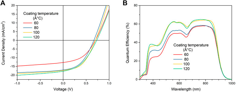
FIGURE 2. (A) J-V curve comparison of devices coated at different temperatures. Measurements done under simulated solar light AM1.5G and 1000 W/m2 and (B) External Quantum Efficiency (QE) of PM6:Y6 solar cells coated at different temperatures.
QEs of the devices increase when coating at higher temperatures (Figure 2B), indicating that coating the active layer at higher temperatures promotes better photon-to-current capabilities, thus a higher current. The discrepancies between the SC obtained through the J-V characteristics and through the QE can be associated to the illuminated area. In case of the quantum efficiency measurements, a spot size of 4 mm2 is illuminated, whereas for the J-V characteristics an illuminated area of 0.4 cm2 is contributing. This means that for the QE measurements a better performing spot than the average might be selected, giving rise to a higher short-circuit current. (Table 1). The short-circuit current measured by J-V characteristics is also higher when increasing the coating temperature. However, the average FF value of 42.2% is lower for the device coated at 120°C than for the one at 100 °C (47.10%). This makes the average PCE of the devices coated at 100°C slightly higher than that obtained when coating at 120 °C. In order to better visualize the tendency of the performance with temperature variations, box plots with statistical data of the PCE and FF evolution of eight devices are shown in Figure 3 (JSC and VOC are shown in Supplementary Figure S4). Each box indicates the first to the third quartile, whereas the median is indicated as a horizontal line and the average as a square. The PCE shows a clear improvement trend towards higher coating temperatures, whose maximum saturates around 100°C, whereas the FF remains around 45% with the lowest average value of 42.2% for the devices coated at 120°C. This may be explained by a detailed look at the dried active layer stripe (Figure 4A,B): When increasing the temperature above 100°C, the solvent is drying much faster, inducing the aggregation of the materials on both edges of the active layer, parallel to the coating direction. This effect creates inhomogeneities along the stripe, which directly impacts the fill factor of the final devices. (Bartesaghi and Koster, 2015).
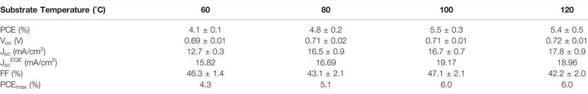
TABLE 1. PV parameters extracted from the J-V curves of PM6:Y6 devices fabricated at different temperatures. Average values are calculated from eight devices, and the standard deviation is shown as the error.
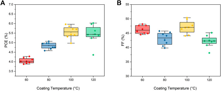
FIGURE 3. Statistic representation of the measured PV parameters of PM6:Y6 devices fabricated at different temperatures: (A) Power Conversion Efficiency (PCE) and (B) Fill Factor (FF).
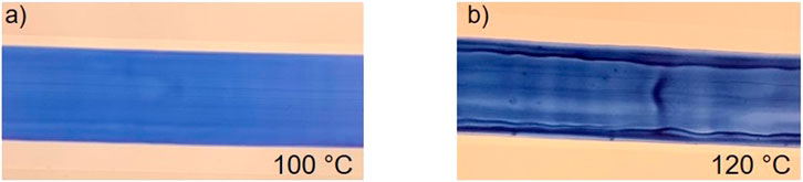
FIGURE 4. PM6:Y6 slot die coated at (A) 100°C and (B) 120°C.
Charge carrier recombination plays a crucial role in the final PV parameters, as recombination means the charges are being lost before being collected at the electrodes. The degree and dominant type of recombination can be studied through light intensity dependence of the current density and open-circuit voltage (Cowan et al., 2010).
In Supplementary Figure S5A, the bimolecular recombination is investigated using the following relation JSC∝ PinS where Pin is the incident light intensity. In an ideal device (all photogenerated charges are extracted at JSC) the photocurrent is expected to scale linearly with light intensity (S = 1). If bimolecular recombination is present, deviations from the unity will be seen (S < 1). When comparing the devices fabricated through the temperature optimization, the devices coated at 100 °C have both a higher PCE and a S value close to unity (S = 0.978), implying that one of the reasons for the optimized performance is due to slightly reduced bimolecular recombination.
In order to obtain independent and complementary information of the recombination processes taking place in our OSCs coated at different temperatures, we estimate the recombination mechanism at open-circuit voltage. At such condition (zero current) where all photocarriers recombine, the type of recombination can be extracted from the slope of the plot VOC versus In(Pin) (Cowan et al., 2010).
The slope is obtained using linear fitting. If the slope is close to kT/q, where k, T, and q are the Boltzmann constant, the absolute temperature, and the element charge respectively, second-order recombination is the most likely the dominant mechanism. Trap-assisted recombination would be dominant recombination mechanism if the slope is larger than kT/q. The results suggest that trap-assisted recombination is the dominant one in the fabricated devices (Supplementary Figure S5B), as all the obtained slope values are higher than kT/q, whereas almost no bimolecular recombination was expected from the current measurements. Regrettably, there is not a clear tendency in the S values compared with the coating variations.
Therefore, based on the higher PCE, the ease of coating a homogeneous layer, and the lack of the extra thermal annealing steps, the optimal temperature was fixed at 100°C.
The active layer thickness also plays an important role in device efficiency. A thicker active layers is responsible for increased light absorption, and it will also make the final device more robust, which is important when roll-to-roll is used, as pressure, bending, and stretching occurs during the process. However, thinner active layer layers allow to have semitransparent devices which are interesting for many applications (Lucera et al., 2017; Zhang et al., 2019; Hu et al., 2020), and also reduce the charge carrier pathways, decreasing the probability of recombination before being collected at the opposite the electrodes. In this study, active layers with four different thicknesses are investigated.
The absorbance peaks of both materials can be clearly distinguished in Supplementary Figure S6A, being the maximum absorbance of the donor at ∼625 nm and the maximum of the acceptor at ∼820 nm. The respective J-V curves for representative devices are shown in Supplementary Figure S6B, whereas a summary of PV parameters of PM6:Y6 –based solar cells with different active layer thicknesses are shown in Table 2. As it is shown in Supplementary Figure S6C, we chose a wide range of concentrations leading to semi-transparent thin layers to thicker and more opaque layers.
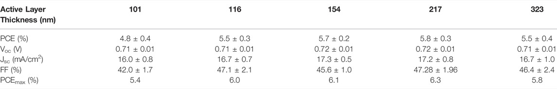
TABLE 2. PV parameters for PM6:Y6-based OSCs devices prepared with different active layer thicknesses. The averages are obtained from eight devices.
The box plots of the PV parameters regarding active layer thickness are shown in Figure 5. As the thickness of the active layer increases from 101 to 217 nm, the average PCE also increases. This is directly related to the increase in the average short-circuit current density (Figure 5C) which reaches its average maximum at 154 nm (17.3 mA/cm2) of active layer thickness, to decrease again slightly at 217 nm of active layer thickness. The FF also improves from the average value of 42.0% for the devices with the thinnest active layer (101 nm) to 47.1% on average for the devices with 116 nm of active layer, with no further improvement at larger active layer thickness. This implies that the active layer in that thickness from 116 to 323 nm does not contribute significantly to an increase of the average series resistance of the devices demonstrating the capability of PM6:Y6 to keep a high performance even when coated as thick layers. The highest PCE obtained in the thickness optimization is 6.3%, with an FF of 49.0%, when coating with ink concentration of 24 mg/ml, equivalent to 217 nm thickness. The average PCE for that active layer thickness is 5.8% (Table 2), the highest average obtained during our optimization procedure.
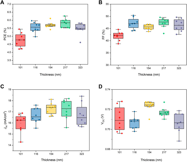
FIGURE 5. Box plots of (A) PCE and (B) FF (C) JSC and (D) VOC of PM6:Y6 devices with different active layer thicknesses.
From the plot of JSC versus Pin (Supplementary Figure S7A) we observe that the solar cell with 217 nm of active layer thickness has the lowest bimolecular recombination with the slope value closest to one in this optimization study (S = 0.987). However, under open-circuit conditions, our solar cells present a high degree of trap-assisted recombination (Supplementary Figure S7B). In that type of recombination electrons and holes recombine in trap states or recombination centers within the materials (due to impurities in the materials) or at the interfaces (Kyaw et al., 2013). It is not surprising that this type of recombination is the dominant when the devices are processed under open-air conditions (Kawano et al., 2006).
Ternary PM6:Y6:PC61BM Devices
The efficiency of PM6:Y6 flexible devices can be increased even further by introducing a ternary compound at the optimal coating temperature and active layer thickness, using a fullerene, PC61BM in our case, as a complementary acceptor. It has been shown that fullerenes enable better electron mobility and more balanced charge transport. (Yu et al., 2019). The LUMO level of PC61BM is between −3.7 and −3.9 eV, located between the LUMO levels of PM6 and Y6, enhancing the energy cascade effect, which is favorable to obtain higher JSC and VOC values (Gasparini et al., 2019). Following previous work on ternary PM6:Y6 blends with fullerenes, (Pan et al., 2019; He et al., 2020), we started with a [1:1:0.2] ratio. Moreover, we also reduced the amount of PCBM in the blend by half, to a [1:1.1:0.1] ratio, in order to determine how the amount of PC61BM influences the performance.
The respective J-V curves are shown in Figure 6A, and their average values are shown in Supplementary Table S2. An enhanced Jsc is clearly visible when a small amount of fullerene acceptor is added to the blend (Figure 7C).
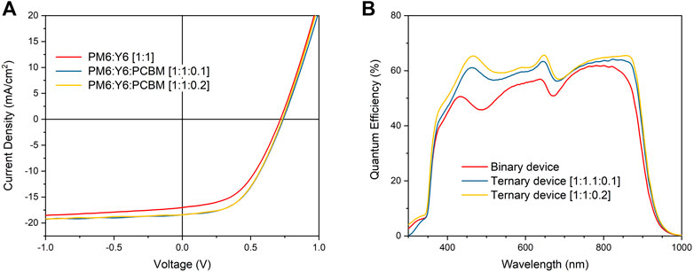
FIGURE 6. (A) J-V curve comparison between binary and ternary devices and (B) QE comparison of PM6:Y6 based solar cells.
JSC values up to 20 mA/cm2 are measured on devices with the [1:1:0.2] ternary blend. On average, a 12% higher JSC is obtained from the [1:1:0.2] ternary blend compared with binary devices coated at the same temperature (100°C) with a 24 mg/ml concentration in O-XY (Supplementary Table S2). Both tested ratios performed at a similar level with PC61BM as the third component. The average PCE of the [1:1:0.2] and [1:1.1:0.1] ternary devices are 6.6 and 6.7%, respectively (Figure 7A). The slightly higher average PCE for the [1:1.1:0.1] ternary devices are due to an average higher FF of 49.1%, compared to 47.3%, for the [1:1:0.2] blends (Figure 7B). A small amount of ternary compound added to the blend is enough to have a positive effect on the current and the FF, and therefore an impact on the overall efficiency of the devices.
When PC61BM is added to the blend as a complementary acceptor, the QEs (Figure 6B) do not show any shape change associated to the PCBM due to the weak and broad absorption of the fullerene acceptor (Yan et al., 2018). Nevertheless, for both ternary blend formulations tested here, keeping the donor/acceptor ratio constant, we observe a photocurrent gain in all the spectral region where the organic layer is photoactive. Figures 7A-D shows a box plot comparing the main photovoltaic parameters of the binary and ternary devices.
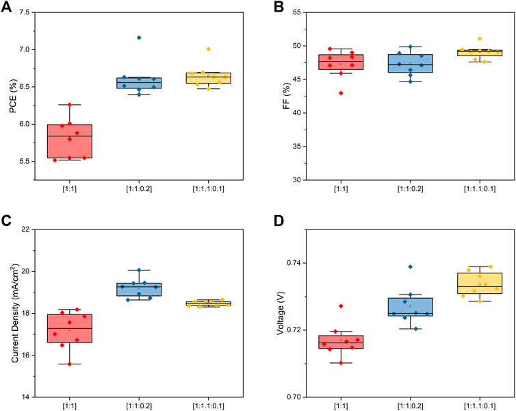
FIGURE 7. Comparison of PV parameters between binary and ternary devices for (A) PCE, (B) FF, (C) current density (Jsc) and (D) open-circuit voltage (Voc).
Calculating the exciton dissociation and charge collection efficiencies (ηdiss and ηcoll) of the binary and ternary devices may reveal the reason of the performance improvement from a photophysical point of view. In order to investigate that, the photocurrent density (Jph) versus the effective voltage (Veff) curves are plotted and analyzed. The photocurrent density is defined as the difference between the current density under illumination (JL) and the dark current density (JD), whereas the effective voltage is defined as the voltage at zero Jph (or VOC) minus the applied voltage bias (Vappl). From the plot presented in Supplementary Figure S8, it is possible to designate the saturated current density (Jsat) from the saturation value for Jph, where all the generated excitons are fully collected, normally reached when Veff > 2V. Jmax is defined as the current at the maximum power point. We calculate ηdiss and ηcoll from Jsc/Jsat and Jmax/Jsat respectively (Supplementary Table S3) (Ma et al., 2020; Jin et al., 2021). The dissociation probability is 93.7% for the binary device, significantly lower than 96.3 and 95.7% obtained for the ternary 1:1:0.2 and 1:1.1:0.1 devices respectively. It shows that one of the benefits of adding PCBM to the blend is the enhancement of the dissociation probability possibly due to the existence of additional and energetically favorable donor/acceptor interfaces. As expected from the higher current density of the ternary devices the collection probability is also improved from 69.6% for the binary device to 77.7 and 73.2% for the ternary 1:1:0.2 and 1:1.1:0.1 devices respectively, confirming for the first time that a better charge extraction can be achieved with a small acceptor fullerene amount in OSCs on flexible substrates and fabricated using slot-die coating on a roll-platform.
Stability
The stability under dark storage for our devices was determined by measuring the encapsulated devices after a certain time stored in dark (up to more than 2 months), at normal room conditions following the ISOS-D-1 protocol (Figure 8) (Reese et al., 2011). The average PCEs measured after 1,050 h for the ternary device retained 99.4% of the average initial value, whereas the average PCEs of binary devices retained more than 97% of the initial average PCE after more than 1,500 h of storage. It is illustrated in Figure 8A with the lines connecting the means of the statistical PCE data of pristine and aged devices. It is worth mentioning that some of the devices showed improved performance after storage time in the case of the ternary device.
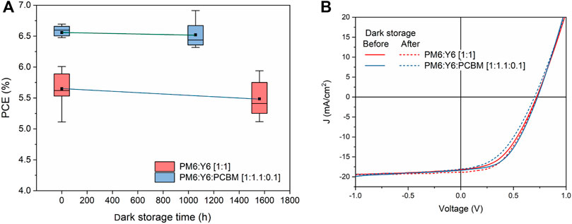
FIGURE 8. (A) Stability of PM6:Y6 devices under dark storage and (B) J-V curves of corresponding devices before and after storage.
Conclusion
Binary and ternary PM6:Y6-based OSCs with average PCE of 5.8% and 6.7% (champion efficiency of 7.2%) respectively were fabricated. The fabrication and optimization were done through slot-die coating on a roll-platform in open-air, using hydrocarbon-based solvents and without additives. This demonstration paves the way for upscaling the production of OSCs based on the outstanding PM6:Y6 system. In order to optimize our devices, we study the effect of the coating temperature. Due to the temperature aggregation behavior of the blend, we used the so-called hot slot-die coating from hot solution, finding that by matching the flexible substrate temperature with that of the hot slot-die head at 100°C, the PCE is maximized because of reduced bimolecular recombination resulting in a higher short-circuit current. The optimal active layer thickness is found to be around 200 nm. However, the FF remains almost unaffected in devices with active layer thickness from ∼100 to ∼300 nm. We confirm that also for the case of PM6:Y6 roll-coated in open-air a small amount of PC61BM improves the JSC due to a photocurrent increase in the photoactive region of the blend (360–900 nm). It is found to be related to a 10% increase in the collection probability in the ternary blends.
In this work, we demonstrate the use of scalable techniques to fabricate high-efficiency OSCs with an active area of ∼0.8 cm2 (measured with a ∼0.4 cm2 shadow mask), to bridge the lab-to-fab gap of the mainstream reports using spin-coated films with active areas <0.1 cm2 fabricated in a glovebox. We aim at stimulating the interests of the field on the important challenge of minimizing the lab-to-fab scalability lag, which is a requeriment for the technology to finally succeed on a global scale.
Data Availability Statement
The data that supports the findings of this study is available from the corresponding author upon reasonable request.
Author Contributions
JT optimized the processes for the fabrication of solar cells. JT, MF-C, and ME-R fabricated the solar cells for this work. JT MF-C and ME-R contributed to the analysis of the data. ME-R and MF-C contributed to the conception and design of the study. JWA wrote sections of the manuscript and acquired funding for the study. All authors contributed to manuscript revision, read, and approved the submitted version.
Funding
We gratefully acknowledge funding from the European Research Council (ERC) under the European Union’s Horizon 2020 research and innovation programme (SEEWHI—Solar Energy Enabled for the World by High Resolution Imaging, Consolidator Grant Nos. 681881). And we acknowledge funding from the Independent Research Fund Denmark through the EPIC-OPV grant no. 1032-00326B.
Conflict of Interest
Author ME-R is employed by FOM Technologies. The remaining authors declare that the research was conducted in the absence of any commercial or financial relationships that could be construed as a potential conflict of interest.
Publisher’s Note
All claims expressed in this article are solely those of the authors and do not necessarily represent those of their affiliated organizations, or those of the publisher, the editors and the reviewers. Any product that may be evaluated in this article, or claim that may be made by its manufacturer, is not guaranteed or endorsed by the publisher.
Acknowledgments
We thank Kristian Larsen for all the technical help that made it possible to carry out this scientific publication. Special acknowledgement to Shinhee Yun (DTU Energy) for conducting the AFM measurements, necessary to have precise thickness measurements of the active layer of our devices.
Supplementary Material
The Supplementary Material for this article can be found online at: https://www.frontiersin.org/articles/10.3389/fnano.2022.885138/full#supplementary-material
References
Armin, A., Li, W., Sandberg, O. J., Xiao, Z., Ding, L., Nelson, J., et al. (2021). A History and Perspective of Non‐Fullerene Electron Acceptors for Organic Solar Cells. Adv. Energ. Mater. 11, 2003570. doi:10.1002/aenm.202003570
Bartesaghi, D., and Koster, L. J. A. (2015). The Effect of Large Compositional Inhomogeneities on the Performance of Organic Solar Cells: A Numerical Study. Adv. Funct. Mater. 25, 2013–2023. doi:10.1002/adfm.201402260
Chang, M., Meng, L., Wang, Y., Ke, X., Yi, Y.-Q. -Q., Zheng, N., et al. (2020). Achieving an Efficient and Stable Morphology in Organic Solar Cells via Fine-Tuning the Side Chains of Small-Molecule Acceptors. Chem. Mater. 32, 2593–2604. doi:10.1021/acs.chemmater.0c00097
Chen, X., Xu, G., Zeng, G., Gu, H., Chen, H., Xu, H., et al. (2020). Realizing Ultrahigh Mechanical Flexibility and >15% Efficiency of Flexible Organic Solar Cells via a “Welding” Flexible Transparent Electrode. Adv. Mater. 32, e1908478. doi:10.1002/adma.201908478
Cowan, S. R., Roy, A., and Heeger, A. J. (2010). Recombination in Polymer-Fullerene Bulk Heterojunction Solar Cells. Phys. Rev. B 82, 245207. doi:10.1103/physrevb.82.245207
Espinosa, N., Hösel, M., Angmo, D., and Krebs, F. C. (2012). Solar Cells with One-Day Energy Payback for the Factories of the Future. Energy Environ. Sci. 5, 5117–5132. doi:10.1039/c1ee02728j
Fernández Castro, M., Mazzolini, E., Sondergaard, R. R., Espindola-Rodriguez, M., and Andreasen, J. W. (2020). Flexible ITO-free Roll-Processed Large-Area Nonfullerene Organic Solar Cells Based on P3HT:O-IDTBR. Phys. Rev. Appl. 14, 034067.
Fernández-Castro, M., Espíndola-Rodríguez, M., Stanzani, E., Sørensen, M. K., Yun, S., and Andreasen, J. W. (2022). Enabling Roll-Processed and Flexible Organic Solar Cells Based on PffBT4T through Temperature-Controlled Slot-Die Coating. IEEE J. Photovoltaics 12, 602. doi:10.1109/JPHOTOV.2021.3136784
Gasparini, N., Salleo, A., McCulloch, I., and Baran, D. (2019). The Role of the Third Component in Ternary Organic Solar Cells. Nat. Rev. Mater. 4, 229–242. doi:10.1038/s41578-019-0093-4
Gertsen, A. S., Fernandez Castro, M., Søndergaard, R. R., and Andreasen, J. W. (2019). Scalable Fabrication of Organic Solar Cells Based on Non-fullerene Acceptors. Flexible Printed Electron. 5, 014004. doi:10.1088/2058-8585/ab5f57
Guo, Q., Guo, Q., Geng, Y., Tang, A., Zhang, M., Du, M., et al. (2021). Recent Advances in PM6:Y6-Based Organic Solar Cells. Mater. Chem. Front. 5, 3257–3280. doi:10.1039/d1qm00060h
He, S., Shen, Z., Yu, J., Guan, H., Lu, G., Xiao, T., et al. (2020). Vertical Miscibility of Bulk Heterojunction Films Contributes to High Photovoltaic Performance. Adv. Mater. Inter. 7, 2000577. doi:10.1002/admi.202000577
Hu, Z., Wang, J., Ma, X., Gao, J., Xu, C., Yang, K., et al. (2020). A Critical Review on Semitransparent Organic Solar Cells. Nano Energy 78, 105376. doi:10.1016/j.nanoen.2020.105376
Jin, L., Ma, R., Liu, H., Xu, W., Luo, Z., Liu, T., et al. (2021). Boosting Highly Efficient Hydrocarbon Solvent-Processed All-Polymer-Based Organic Solar Cells by Modulating Thin-Film Morphology. ACS Appl. Mater. Inter. 13, 34301. doi:10.1021/acsami.1c07946
Kawano, K., Pacios, R., Poplavskyy, D., Nelson, J., Bradley, D. D. C., and Durrant, J. R. (2006). Degradation of Organic Solar Cells Due to Air Exposure. Solar Energ. Mater. Solar Cell 90, 3520–3530. doi:10.1016/j.solmat.2006.06.041
Kyaw, A. K. K., Wang, D. H., Gupta, V., Leong, W. L., Ke, L., Bazan, G. C., et al. (2013). Intensity Dependence of Current-Voltage Characteristics and Recombination in High-Efficiency Solution-Processed Small-Molecule Solar Cells. ACS Nano 7, 4569–4577. doi:10.1021/nn401267s
Larsen, C., Lundberg, P., Tang, S., Ràfols-Ribé, J., Sandström, A., Mattias Lindh, E., et al. (2021). A Tool for Identifying green Solvents for Printed Electronics. Nat. Commun. 12, 4510. doi:10.1038/s41467-021-24761-x
Li, W., Chen, M., Cai, J., Spooner, E. L. K., Zhang, H., Gurney, R. S., et al. (2019). Molecular Order Control of Non-fullerene Acceptors for High-Efficiency Polymer Solar Cells. Joule 3, 819–833. doi:10.1016/j.joule.2018.11.023
Li, Y., Zheng, N., Yu, L., Wen, S., Gao, C., Sun, M., et al. (2019). A Simple Phenyl Group Introduced at the Tail of Alkyl Side Chains of Small Molecular Acceptors: New Strategy to Balance the Crystallinity of Acceptors and Miscibility of Bulk Heterojunction Enabling Highly Efficient Organic Solar Cells. Adv. Mater. 31, 1807832. doi:10.1002/adma.201807832
Liang, Z., Li, M., Wang, Q., Qin, Y., Stuard, S. J., Peng, Z., et al. (2020). Optimization Requirements of Efficient Polythiophene:Nonfullerene Organic Solar Cells. Joule 4, 1278–1295. doi:10.1016/j.joule.2020.04.014
Liao, H.-C., Ho, C.-C., Chang, C.-Y., Jao, M.-H., Darling, S. B., and Su, W.-F. (2013). Additives for Morphology Control in High-Efficiency Organic Solar Cells. Mater. Today 16, 326–336. doi:10.1016/j.mattod.2013.08.013
Liu, Q., Jiang, Y., Jin, K., Qin, J., Xu, J., Li, W., et al. (2020). 18% Efficiency Organic Solar Cells. Sci. Bull. 65, 272. doi:10.1016/j.scib.2020.01.001
Liu, T., Huo, L., Chandrabose, S., Chen, K., Han, G., Qi, F., et al. (2018). Optimized Fibril Network Morphology by Precise Side‐Chain Engineering to Achieve High‐Performance Bulk‐Heterojunction Organic Solar Cells. Adv. Mater. 30, 1707353. doi:10.1002/adma.201707353
Liu, X., Liang, Z., Du, S., Tong, J., Li, J., Zhang, R., et al. (2021). Non-Halogenated Polymer Donor-Based Organic Solar Cells with a Nearly 15% Efficiency Enabled by a Classic Ternary Strategy ACS. Appl. Energ. Mater. 4, 1774. doi:10.1021/acsaem.0c02912
Lucera, L., Machui, F., Schmidt, H. D., Ahmad, T., Kubis, P., Strohm, S., et al. (2017). Printed Semi-transparent Large Area Organic Photovoltaic Modules with Power Conversion Efficiencies of Close to 5 %. Org. Electron. 45, 209. doi:10.1016/j.orgel.2017.03.013
Ma, R., Li, G., Li, D., Liu, T., Luo, Z., Zhang, G., et al. (2020). Understanding the Effect of End Group Halogenation in Tuning Miscibility and Morphology of High‐Performance Small Molecular Acceptors. Sol. RRL 4, 2000250. doi:10.1002/solr.202000250
Na, S. I., Seo, Y. H., Nah, Y. C., Kim, S. S., Heo, H., Kim, J. E., et al. (2019). High Performance Roll‐to‐Roll Produced Fullerene‐Free Organic Photovoltaic Devices via Temperature‐Controlled Slot Die Coating. Adv. Funct. Mater. 29, 1805825. doi:10.1002/adfm.201805825
Pan, M. A., Lau, T. K., Tang, Y., Wu, Y. C., Liu, T., Li, K., et al. (2019). 16.7%-efficiency Ternary Blended Organic Photovoltaic Cells with PCBM as the Acceptor Additive to Increase the Open-Circuit Voltage and Phase Purity. J. Mater. Chem. A 7, 20713. doi:10.1039/C9TA06929A
Pang, Z., Zhang, W., Wu, J., Luo, Y., Liu, J., Zhao, S., et al. (2020). Insight into the Effects of Alkoxy Side Chain Position in Nonfullerene Electron Acceptors on the Morphological Stability of Organic Solar Cells. Dyes Pigm. 181, 108562. doi:10.1016/j.dyepig.2020.108562
Qin, F., Sun, L., Chen, H., Liu, Y., Lu, X., Wang, W., et al. (2021). 54 Cm2 Large-Area Flexible Organic Solar Modules with Efficiency above 13. Adv. Mater. 33, e2103017. doi:10.1002/adma.202103017
Reese, M. O., Gevorgyan, S. A., Jørgensen, M., Bundgaard, E., Kurtz, S. R., Ginley, D. S., et al. (2011). Consensus Stability Testing Protocols for Organic Photovoltaic Materials and Devices. Solar Energ. Mater. Solar Cell 95, 1253–1267. doi:10.1016/j.solmat.2011.01.036
Søndergaard, R., Hösel, M., Angmo, D., Larsen-Olsen, T. T., and Krebs, F. C. (2012). Roll-to-roll Fabrication of Polymer Solar Cells. Mater. Today 15, 36. doi:10.1016/S1369-7021(12)70019-6
Song, X., Gasparini, N., Ye, L., Yao, H., Hou, J., Ade, H., et al. (2018). Controlling Blend Morphology for Ultrahigh Current Density in Nonfullerene Acceptor-Based Organic Solar Cells. ACS Energ. Lett. 3, 669–676. doi:10.1021/acsenergylett.7b01266
Wang, G., Zhang, J., Yang, C., Wang, Y., Xing, Y., Adil, M. A., et al. (2020). Synergistic Optimization Enables Large-Area Flexible Organic Solar Cells to Maintain over 98% PCE of the Small-Area Rigid Devices. Adv. Mater. 32, e2005153. doi:10.1002/adma.202005153
Wang, W., Wu, Q., Sun, R., Guo, J., Wu, Y., Shi, M., et al. (2020). Controlling Molecular Mass of Low-Band-Gap Polymer Acceptors for High-Performance All-Polymer Solar Cells. Joule 4, 1070–1086. doi:10.1016/j.joule.2020.03.019
Würfel, U., Herterich, J., List, M., Faisst, J., Bhuyian, M. F. M., Schleiermacher, H-F., et al. (2021). A 1 Cm2 Organic Solar Cell with 15.2% Certified Efficiency: Detailed Characterization and Identification of Optimization Potential. Solar RRL 5, 2000802. doi:10.1002/solr.202000802
Xue, P., Cheng, P., Han, R. P. S., and Zhan, X. (2021). Printing Fabrication of Large-Area Non-fullerene Organic Solar Cells. Mater. Horizons 9, 194. doi:10.1039/D1MH01317C
Yan, C., Barlow, S., Wang, Z., Yan, H., Jen, A. K.-Y., Marder, S. R., et al. (2018). Non-fullerene Acceptors for Organic Solar Cells. Nat. Rev. Mater. 3, 18003. doi:10.1038/natrevmats.2018.3
Yang, F., Huang, Y., Li, Y., and Li, Y. (2021). Large-area Flexible Organic Solar Cells. Npj Flex Electron. 5, 30. doi:10.1038/s41528-021-00128-6
Yu, R., Yao, H., Cui, Y., Hong, L., He, C., and Hou, J. (2019). Improved Charge Transport and Reduced Nonradiative Energy Loss Enable over 16% Efficiency in Ternary Polymer Solar Cells. Adv. Mater. 31, e1902302. doi:10.1002/adma.201902302
Zhang, J., Xu, G., Tao, F., Zeng, G., Zhang, M., YangMichael, Y, Li, Y., and Li, Y. (2019). Highly Efficient Semitransparent Organic Solar Cells with Color Rendering Index Approaching 100. Adv. Mater. 31, 1807159. doi:10.1002/adma.201807159
Zhao, F., Wang, C., and Zhan, X. (2018). Morphology Control in Organic Solar Cells. Adv. Energ. Mater. 8, 1703147. doi:10.1002/aenm.201703147
Keywords: hydrocarbon-based solvent, additive-free, roll-processed, flexible, large area, PM6, Y6, organic solar cell
Citation: Fernández-Castro M, Truer J, Espindola-Rodriguez M and Andreasen JW (2022) Environmentally Friendly and Roll-Processed Flexible Organic Solar Cells Based on PM6:Y6. Front. Nanotechnol. 4:885138. doi: 10.3389/fnano.2022.885138
Received: 27 February 2022; Accepted: 06 April 2022;
Published: 09 May 2022.
Edited by:
Jihua Chen, Oak Ridge National Laboratory (DOE), United StatesCopyright © 2022 Fernández-Castro, Truer, Espindola-Rodriguez and Andreasen. This is an open-access article distributed under the terms of the Creative Commons Attribution License (CC BY). The use, distribution or reproduction in other forums is permitted, provided the original author(s) and the copyright owner(s) are credited and that the original publication in this journal is cited, in accordance with accepted academic practice. No use, distribution or reproduction is permitted which does not comply with these terms.
*Correspondence: Moises Espindola-Rodriguez, mos@fomtechnologies.com