


- 1 Laboratory for Neuroengineering, The Wallace H. Coulter Department of Biomedical Engineering, Georgia Institute of Technology, Atlanta, GA, USA
- 2 Department of Neurosurgery, Emory University School of Medicine, Atlanta, GA, USA
Implantable microelectrode arrays (MEAs) have been a boon for neural stimulation and recording experiments. Commercially available MEAs have high impedances, due to their low surface area and small tip diameters, which are suitable for recording single unit activity. Lowering the electrode impedance, but preserving the small diameter, would provide a number of advantages, including reduced stimulation voltages, reduced stimulation artifacts and improved signal-to-noise ratio. Impedance reductions can be achieved by electroplating the MEAs with platinum (Pt) black, which increases the surface area but has little effect on the physical extent of the electrodes. However, because of the low durability of Pt black plating, this method has not been popular for chronic use. Sonicoplating (i.e. electroplating under ultrasonic agitation) has been shown to improve the durability of Pt black on the base metals of macro-electrodes used for cyclic voltammetry. This method has not previously been characterized for MEAs used in chronic neural implants. We show here that sonicoplating can lower the impedances of microwire multi-electrode arrays (MMEA) by an order of magnitude or more (depending on the time and voltage of electroplating), with better durability compared to pulsed plating or traditional DC methods. We also show the improved stimulation and recording performance that can be achieved in an in vivo implantation study with the sonicoplated low-impedance MMEAs, compared to high-impedance unplated electrodes.
Introduction
Implantable microelectrode arrays (MEAs) have been used to record and stimulate in a number of studies in different regions of the brain (Branner et al., 2001 ; Vetter et al., 2004 ; McCreery et al., 2006 ; Cogan, 2008 ). Microwire multi-electrode arrays (MMEAs) have been used widely in studies requiring both chronic and acute (<1 day) recordings and stimulations (Nicolelis et al., 1997 ; Buzsaki, 2004 ; Deadwyler and Hampson, 2004 ; Shi et al., 2007 ; Ganguly et al., 2009 ; O’Doherty et al., 2009 ; Venkatraman et al., 2009 ). They have especially gained prominence because of the wide range of array shapes and sizes available (including number of electrodes, length, spacing, insulation, diameter, impedance, tip shape, etc.), to suit different needs.
The stimulation parameters (voltage, pulse length, etc.) that are required to evoke neural responses using the MMEAs are dependent on the impedance of the electrodes. It would be ideal for the electrodes to have low impedance because this would directly reduce the amount of voltage required to produce a given current, and in turn evoke the desired response. Lowering the required stimulation voltage is expected to help avoid several problems:
First, when electrodes immersed in saline solutions are driven to high enough voltages, electrolysis occurs, wherein water is irreversibly split into O2 and H2 gases (Merrill et al., 2005 ). For platinum (Pt) electrodes, Rose and Robblee (1990) have reported that the maximum charge density that can be applied without the electrode potential exceeding the water window (or causing electrolysis of water) is 50–100 μC/cm2 using anodic-first pulses and 100–150 μC/cm2 using cathodic-first pulses. For platinum (Pt) electrodes of a few micrometers in diameter the electrolysis limit is determined to be above 1 V (at which oxidation of the electrode begins) or below −0.8 V (at which hydrogen evolution begins) (Rozman et al., 2000 ). Lowering the impedance of stimulating electrodes would allow for higher currents to be passed before causing electrolysis.
Second, in simultaneous stimulation and recording experiments, stimulation artifacts are undesirable because they make detection of action potentials difficult or impossible in the time period for which they last (Wagenaar and Potter, 2002 ; Rolston et al., 2009 ). Signal processing algorithms like SALPA (Wagenaar and Potter, 2002 ) suppress stimulation artifacts on the non-stimulating electrodes but do not work well on the stimulating electrode itself if the stimulus saturates the preamplifier, filters or analog-to-digital converter. Lowering the impedance of electrodes by increasing their surface area will also increase their capacitance. Increasing capacitance will have the effect of reducing the capacitive voltage for a given stimulation current. Since capacitive voltage is the main culprit in prolonging stimulation artifacts, lowering it should reduce the duration of the artifacts. Lower impedances allow reduced stimulation voltages and this will also reduce the amplitude of stimulation artifacts (Ross et al., 2004 ).
Third, thermal noise (also known as the Johnson-Nyquist noise) is directly proportional to electrode impedance (Johnson, 1928 ; Nyquist, 1928 ) and will also be reduced by lowering the impedance of electrodes. Reducing thermal noise should help in improving the signal-to-noise ratio of neural recordings.
All this calls for MMEAs with reduced impedance. Ideally, impedance should be reduced by increasing surface area without increasing the physical extent of the electrodes. Otherwise, we would compromise on single unit selectivity. Electroplated Pt black is non-toxic (Dymond et al., 1970 ) and has a high surface area but traditionally is very delicate and not suitable for chronic use. In the field of cyclic voltammetry, Marrese has shown that plating electrodes with Pt black under ultrasonic agitation increases their surface area with higher durability (Marrese, 1987 ). However, to the best of our knowledge, this technique has not previously been characterized for neural recording and stimulation on microelectrodes used in chronic implants.
Here, we study the durability of Pt black plated on MMEAs under ultrasonic vibration (“sonicoplating”) in chronic implants. We also show explicitly the improvements that durably plated MMEAs can have over unplated MEAs for in vivo recording and stimulation performance. Pulsed plating is another technique that has been proposed for improving the durability of Pt black plating (Gladstein and Guterman, 2001 , 2005 ). We compared the durabilities of Pt black plated through sonicoplating, pulsed plating and DC plating by scanning electron microscopy (SEM), impedance spectroscopy and measurements of in vivo stimulation and recording.
Materials and Methods
Plating Solution Preparation
We followed the protocol for the plating solution from Marrese (1987) . For 200 ml of chloroplatinic acid plating solution, we added 200 ml of ultrapure (>10 Mohm/cm) water, 20 mg of lead acetate trihydrate (Sigma-Aldrich) (lead ions have been shown to increase the adherence of Pt black on the substrate), 5 μl of 1 N HCl and 2 g of chloroplatinic acid hydrate (Aldrich) at room temperature (25°C).
Electroplating Setup
The electroplating setup used consists of a cathode (the MMEA that is to be plated), an anode (a strip of Pt metal) and the electrolyte (Pt electroplating solution) immersed in a standard ultrasonic bath agitator (sonicator) (Sonicor model DSC-101TH) used to provide agitation in the ultrasonic frequency range. The sonicator that we used in our study had output vibrations of 40,000 Hz at 276 W.
Voltage-controlled electroplating was performed on all trials at room temperature using the setup depicted in Figure 1 . Input current for electroplating was provided by our open-source NeuroRighter multi-electrode electrophysiology setup (Rolston et al., 2009 ). The use of NeuroRighter made intermittent impedance measurements in vivo and in vitro fast and easy.
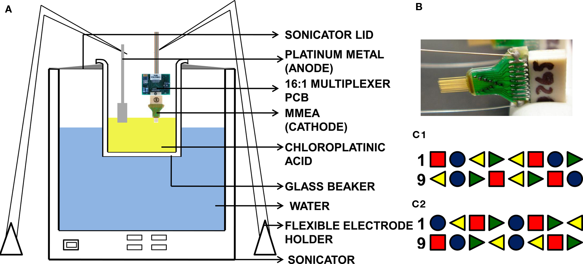
Figure 1. (A) Setup used in the sonicoplating experiment consists of a cathode (MMEA – the base metal to be electroplated), an anode (a strip of Pt metal) and the electrolyte (chloroplatinic acid plating solution) in a standard 500 ml Pyrex glass beaker placed in an ultrasonic agitator. Flexible arm probe holders are used to hold the MMEA and Pt counter-electrode. The same setup is used for pulsed plating and DC plating with the ultrasonic agitator switched off. Electroplating current comes from NeuroRighter, which is programmed to deliver voltage-controlled DC current or pulsed current of appropriate amplitude and duration. (B) MMEA (Tucker Davis Technologies) with tungsten electrodes insulated with polyimide. (C) Of the sixteen electrodes in the microwire array, four are sonicoplated (red square), four are pulsed plated (green right triangle), four are DC plated (yellow left triangle) and four are left unplated (blue circle). (C1,C2) Show the sixteen plated and unplated electrodes in MMEAs used in our durability and in vivo studies respectively. Time and voltage for plating were chosen so that the three types of plating produced similar final impedance values.
The MMEAs (Tucker-Davis Technologies) that we used in our experiments had sixteen electrodes of 33-μm diameter arranged in two rows of 8 electrodes, with 175 μm between electrodes within a row, and 1 mm between rows. The electrodes are made of a tungsten core insulated with polyimide. There is a thin layer of gold between the tungsten and polyimide which enables soldering of the electrode to the connector. The sixteen electrodes on the MMEA were divided into four groups of four interleaved electrodes (each group had one electrode each from electrode numbers 1–4, 5–8, 9–12 and 13–16). We sonicoplated one of the four groups, pulsed-plated the second, DC plated the third and left the fourth group unplated to serve as a control. The microwire electrodes were plated one at a time by the three different plating techniques until their impedances were brought down to the same level. This was made possible by interfacing a 16:1 multiplexer circuit with NeuroRighter. So that only the sonicoplated electrodes were exposed to sonication, the order of plating was (1) sonicoplating, followed by (2) pulsed plating followed by (3) DC plating.
Surgery, Recordings, Stimulations and Impedance Measurements
Animal work was conducted in accordance with the National Institutes of Health Guide for the Care and Use of Laboratory Animals and approved by the Emory University Institutional Animal Care and Use Committee. An adult male Sprague-Dawley rat weighing ≥350 g was used for our in vivo durability, stimulation and recording tests. For the duration of the surgery, the rat was kept anesthetized with 1–3% inhaled isofluorane. A craniectomy was made over the right dorsal hippocampus, centered at 3.5 mm posterior and 2.8 mm lateral to bregma. The dura was removed with a sterile needle. An electroplated 18-electrode MMEA, whose impedances were brought down to the same levels by the three different plating methods on 4 electrodes each (according to the method in the “Electroplating Setup” section was slowly implanted into the brain to a depth of ∼3.7 mm (in addition to the 16 normal electrodes, the MMEA also had two longer (6 mm) ground and reference electrodes). Skull screws were implanted and dental acrylic was applied to seal the craniectomy. Buprenorphine (0.05 mg/kg) was injected and the rat was allowed to rest for 6 days before subsequent impedance studies began.
Impedances were measured by stimulating with sine waves of amplitude 1 μA across the frequency range of 10–10000 Hz. To compare stimulation voltages required (for a fixed simulation current) on the three different types of plated and unplated electrodes, ten ±10-μA biphasic current-controlled pulses of 800-μs duration (50% duty cycle) were delivered on one electrode at a time while simultaneously recording (at 25 kHz) from all sixteen electrodes. Stimulation artifacts (<1 ms) on the non-stimulating electrodes were removed in real-time with the SALPA algorithm (Wagenaar and Potter, 2002 ).
Results
Test for Durability
We tested the durability of the Pt black plating by subjecting an electroplated 16-electrode MMEA, whose impedances were brought down to the same levels by the three different plating methods on 4-electrodes each (according to the method in the “Electroplating Setup” section) to additional sonication in physiological saline solution. The hypothesis is that additional sonication will remove any loosely bonded Pt black particles, showing which plating technique produces the most durably plated layer. As seen from Figure 2 , at the end of 60 min of ultrasonic agitation in saline, all three types of plated electrodes showed an increase in the impedance levels compared to their impedance values immediately after plating, indicating that there is a loss in Pt black plated by all three methods. However this increase was much more pronounced in the DC and pulsed plated electrodes. As seen from Figures 2 A–C, at 1 kHz there is a 63 ± 16% increase in the impedance of the sonicoplated electrodes after 60 min of additional sonication as opposed to 297 ± 18% increase and 353 ± 72 % increase in the pulsed plated and DC plated cases.
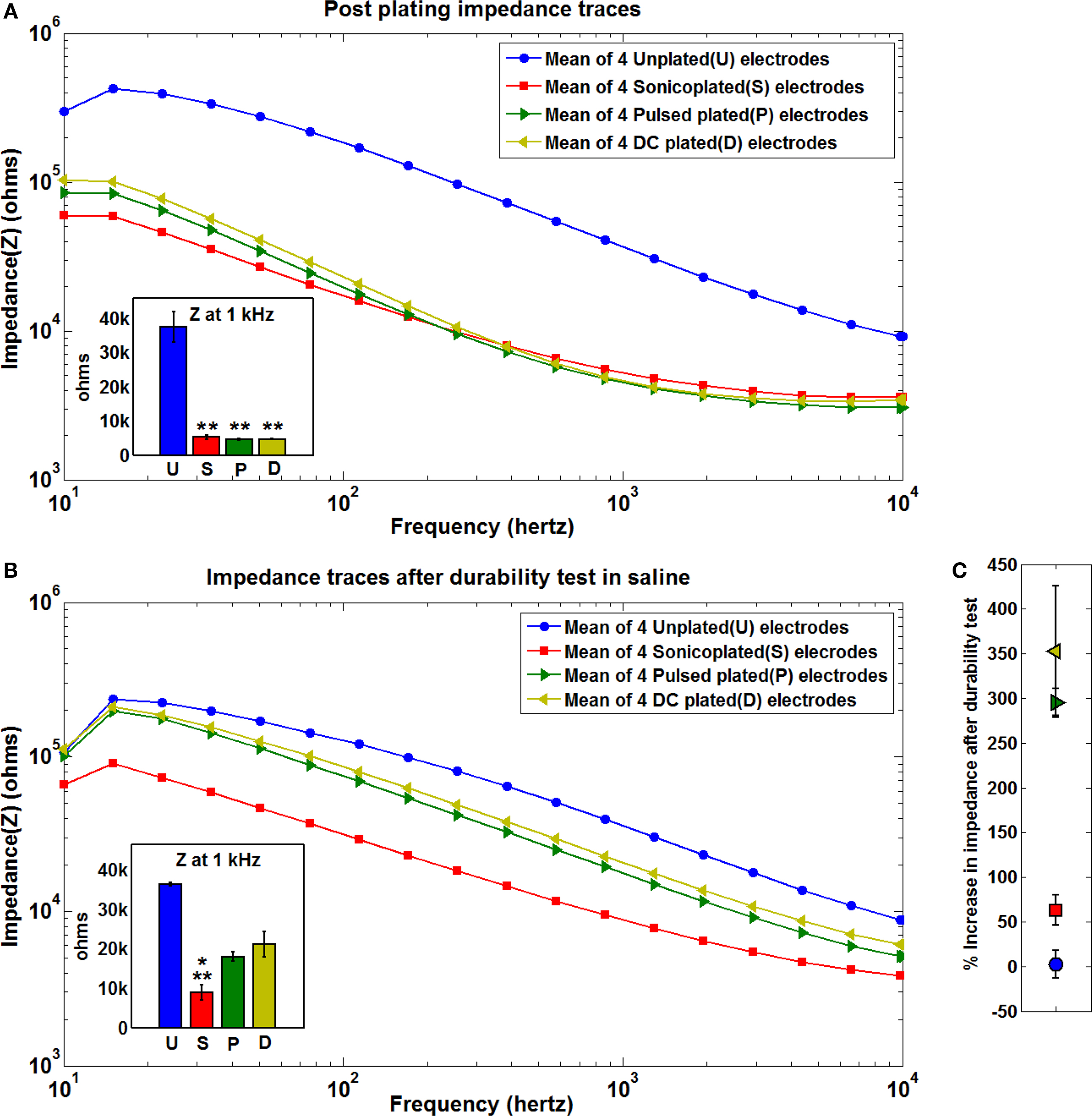
Figure 2. Impedance spectra. (A) Postplating mean impedance spectra of the three types of plated and unplated electrodes. Each log-log plot shows the mean impedance value of four electrodes that were subject to the same type of plating treatment. The inset at the bottom left shows the mean impedance values of the three types of plating at 1 kHz (blue – unplated, red – sonicoplated, green – pulsed plated, yellow – DC plated) with the error bars representing the standard error of the mean. Impedance values were recorded in physiological saline solution with the help of NeuroRighter (Rolston et al., 2009 ),**p < 0.001 (t-test) compared to unplated electrodes (B) Mean impedance traces of the same electrodes after being subjected to 60 min of sonication in saline.**p = 0.001 compared to control; *p < 0.05 compared to pulsed plated and DC plated electrodes. (C) Percentage increase in the impedance values after 60 min of additional sonication in saline. Values are calculated from the mean post plating and post additional sonication values at 1 kHz for the three types of plated and the unplated electrodes.
Scanning Electron Microscopy (SEM) was carried out before and after the durability test to see if there was a difference in surface morphology of the Pt black plating formed by the three plating techniques. As seen from Figure 3 , there was a remarkable difference in the way Pt black plating forms by the three plating techniques. In the sonicoplated electrodes (Figures 3 e–h), there is a more uniform, thin layer of plating formed when compared to the pulsed plated (Figures 3 i–l) and the DC plated cases (Figures 3 m–p) where Pt black forms distinct lumps. This is presumably because in the case of sonicoplating, only those Pt black particles that formed strong bonds with either the base metal or with other Pt particles remain attached during the process of plating. Via this nano-scale type of Darwinian selection during sonicoplating (Marrese, 1987 ), the weaker bonds are broken and the weakly bonded Pt particles leave the plating, forming a more uniform and adherent Pt layer on the base metal. The DC and pulsed plating techniques, on the other hand, presumably allow weak and strong bonds to remain in the plating. This is suggested by the loss of many Pt lumps upon 1-hour sonication of the pulsed and DC plated electrodes.
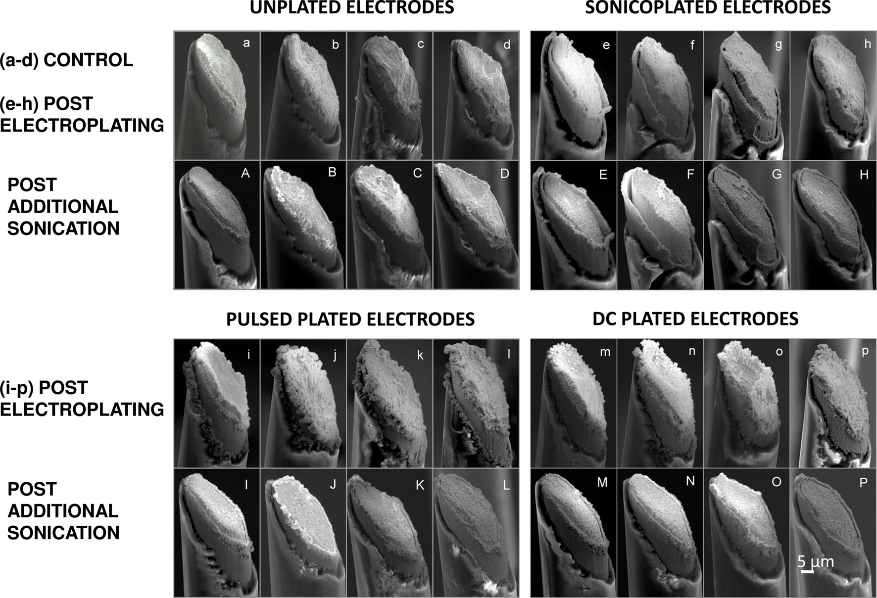
Figure 3. SEM images of microwire electrode tips that are cut at a 45° angle. Small letters (starting with (e)) denote images of electrodes whose impedances are brought down to the same level by the three different plating methods. (a–d) unplated electrodes (e–h) sonicoplated electrodes (i–l) pulsed plated electrodes (m–p) DC plated electrodes. Capital letters denote SEM images of the same electrodes after 60 min of ultrasonic agitation in saline. (A–D) unplated electrodes (E–H) sonicoplated electrodes (I–L) pulsed plated electrodes (M–P) DC plated electrodes.
Matching Electrode Impedance Under Different Plating Conditions
We did a number of pilot experiments to come up with an estimate of the time and voltage required for the three plating techniques to undergo a similar reduction in impedance. Table 1 reports the values used for this study, showing that the sonicoplating technique requires more time and voltage than the other two plating techniques. Since plating under ultrasonic agitation allows only strong bonds to remain, knocking off weakly bonded Pt particles, it requires more net charge for this method to achieve a similar reduction in impedance.
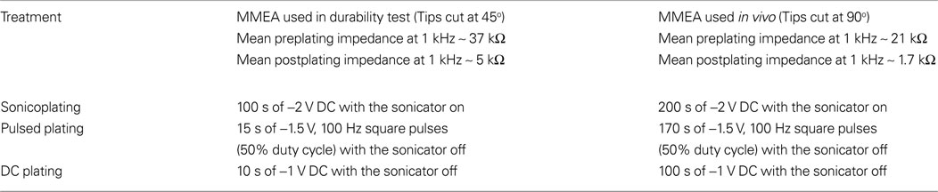
Table 1. Electroplating parameters used for the three plating techniques to achieve the same reduction in impedance.
Chronic MMEA Implantation in vivo
In order to look at the improvements that reducing impedance can have in an actual recording and stimulation experiment and also to look at the durability of Pt black plating in a chronic study, we implanted an electroplated MMEA (according to the method in the “Electroplating Setup” section, with no sonication of pulsed or DC plated electrodes) into a rat’s hippocampus and followed the impedances over a period of three weeks. As seen from Figure 4 , the difference in the impedances between the three types of plating was not as noticeable as in our durability test in saline. However, it should be noted that the impedances in an in vivo environment are affected by variable factors such as gliosis (Rudge et al., 1989 ; Polikov et al., 2005 ) making it difficult to follow the impedance contributions of the electrodes themselves. The impedances on the plated electrodes remained significantly lower than the unplated electrodes at 3 weeks post implantation (p < 0.001, t-test). In fact, the sonicoplated electrodes had, on average, lower impedances than electrodes with other types of plating, throughout the course of three weeks (p < 0.35).
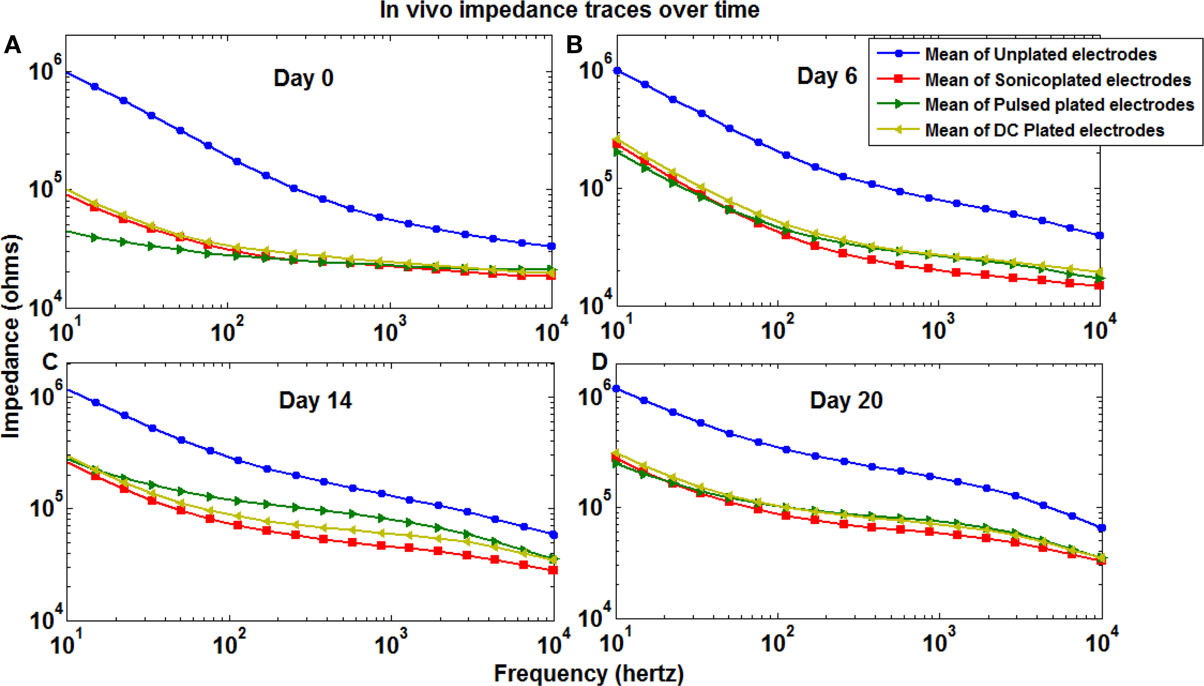
Figure 4. Mean impedance spectra of the three types of plated and unplated electrodes in an in vivo MMEA immediately after implantation (A) and after 6 (B), 14 (C) and 20 (D) days.
Single Unit Activity Recorded on Electroplated Electrodes
To confirm that the electroplated Pt black increased the surface area of electrodes without compromising single-unit selectivity (e.g. from an increase in the electrode’s physical extent), we looked at 5 min of spontaneous recording on the plated and unplated electrodes. Clustering of spontaneous action potentials recorded on each electrode was performed using Wave_clus (Quiroga et al., 2004 ). Each type of electroplated electrode recorded normal single unit action potential waveforms similar to the unplated electrodes indicating that the increase in electrode surface is achieved without sacrificing single-unit selectivity (Figure 5 ). Although Pt black electroplating did not compromise single-unit selectivity, it did not improve it either.
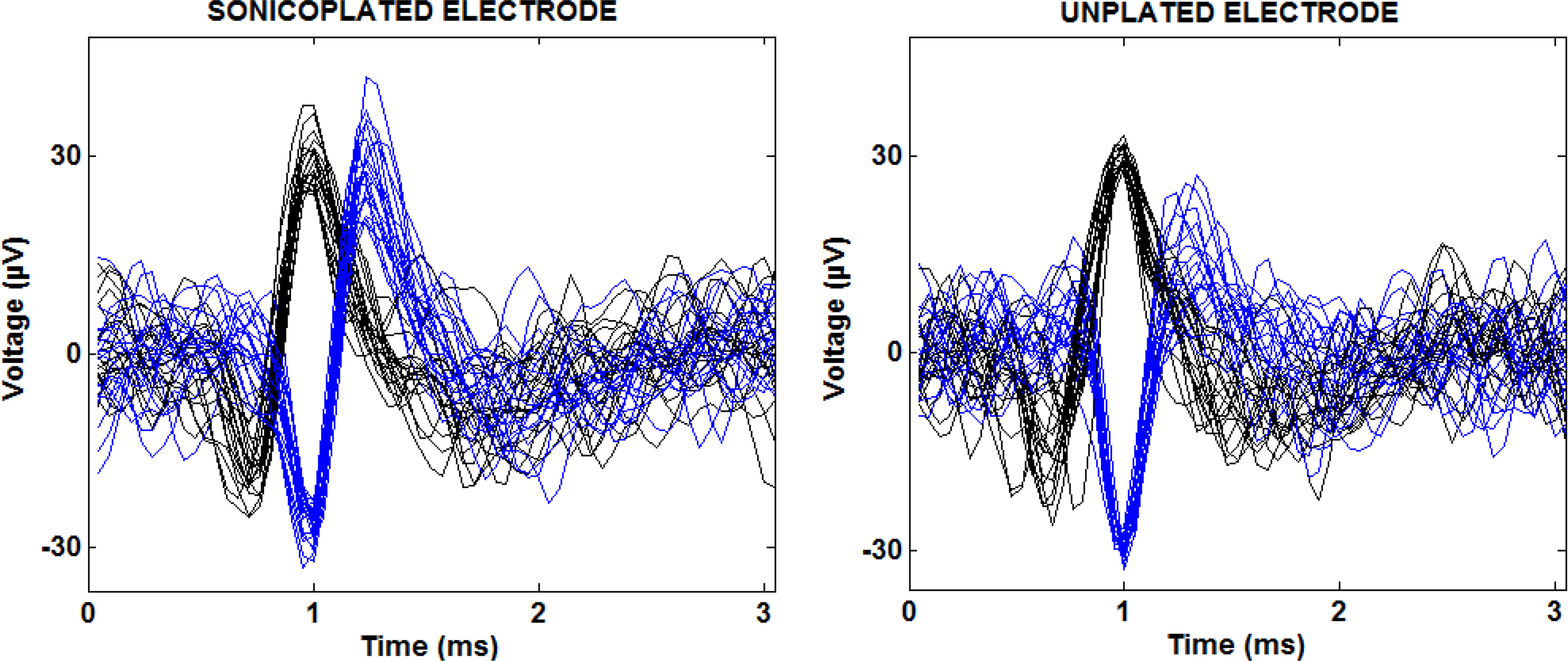
Figure 5. Multiple separable spike waveforms recorded on a single sonicoplated and an unplated electrode in a 5 min spontaneous recording. The blue and black traces show two distinct units recorded on a single electrode with twenty of their action potential waveforms overlaid.
Reduction in Stimulation Voltage
By Ohm’s law, the stimulation voltage required to pass a given current is directly proportional to the electrode impedance. Therefore, lowering impedance would directly translate to lowering the stimulation voltage required to evoke a response. This was verified experimentally in a chronically implanted MMEA as depicted in Figure 6 . The sonicoplated electrodes had the lowest mean impedance of the three types of plating, and as expected had the maximum reduction in stimulation voltage. For a stimulation current of 10 μA, the unplated electrodes required a mean voltage of about 1.13 V, whereas the sonicoplated electrodes required a mean voltage less than 0.64 V. This is a 43% reduction in stimulation voltage.
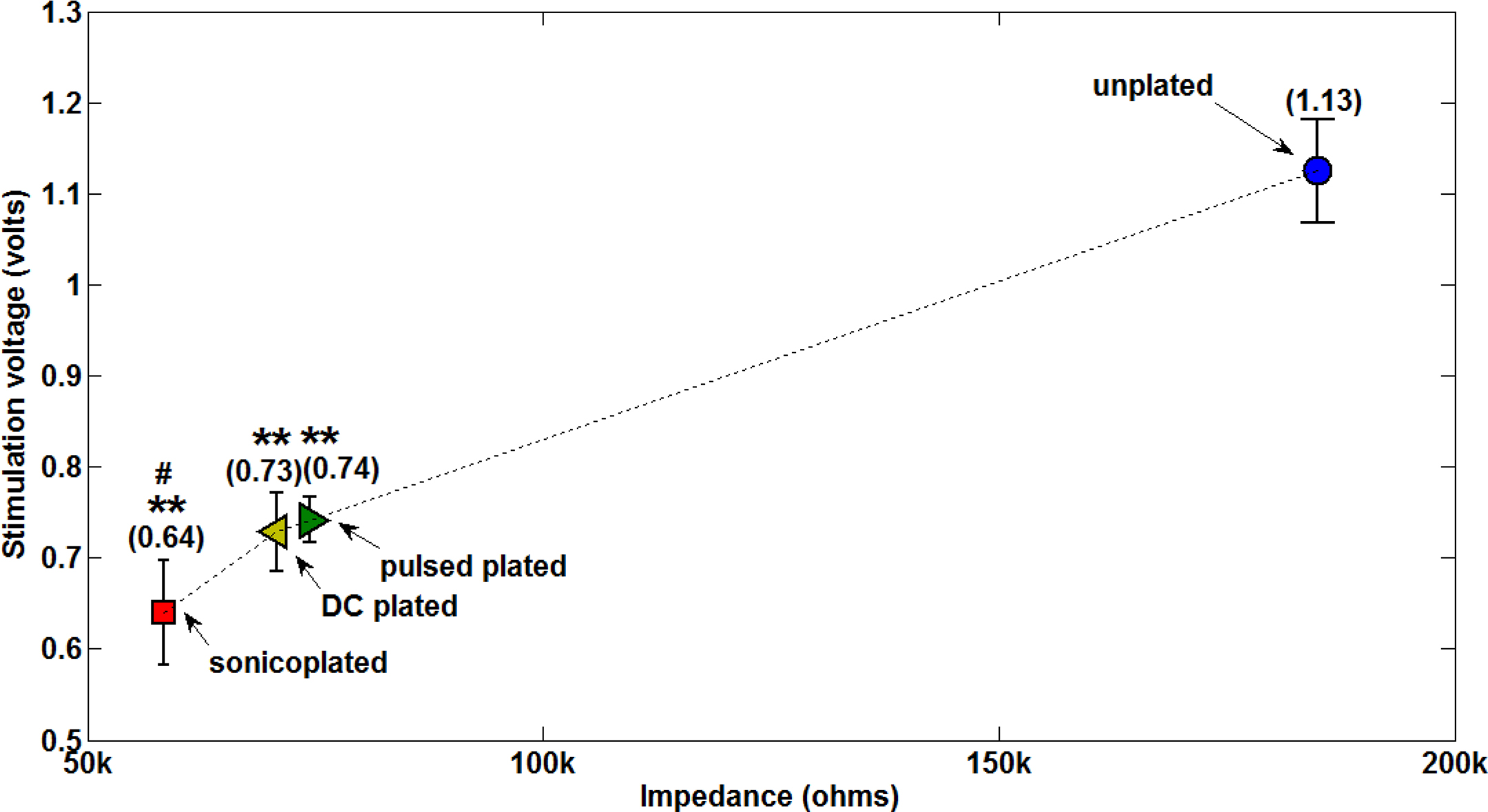
Figure 6. Stimulation voltages required on electrodes of different impedances to deliver an output current of 10 μA. For a fixed output current set in NeuroRighter, the stimulation voltage was measured on all electrodes on Day 20 post implantation. Data represents mean ± standard error on the four electrodes that have the same type of plating. Values in parentheses show the mean. **p < 0.003 compared with unplated electrodes; #p < 0.21 compared with pulsed plated and DC plated electrodes.
Reduction of Stimulation Artifacts
Extracellular electrical stimuli (∼1 V) are typically five orders of magnitude larger than extracellularly recorded neural signals (∼10 μV). This makes recording spikes evoked by stimuli difficult due to large stimulation artifacts. Capacitive charge accumulation between the stimulating electrode and the surrounding tissue impedes or prevents the detection of spikes for the time period for which the stimulation artifacts persist. In many cases, recording electronics become saturated for tens of milliseconds post stimulation (Rolston et al., 2009 ). As shown in Figure 7 , a substantial reduction in the impedance on the stimulating electrode can reduce stimulation artifacts to a great extent. Since the sonicoplated electrodes require the lowest voltage for a 10 μA stimulus, compared to the other types of plating, they have the least stimulation artifact (in terms of amplitude and duration). The amplitudes and durations of the stimulation artifacts for the different types of plated electrodes compared to the unplated electrodes are quantified in Figure 8 . The durations of the artifacts were reduced to about 8.6 ms on the sonicoplated electrodes compared to 482 ms in the unplated case. This is a 98% reduction in the duration of stimulation artifacts on the sonicoplated electrodes (p < 0.01). The amplitude of the artifacts was also reduced by 83% (p < 0.005). Similar reductions were observed on the unplated and DC plated electrodes too, but the results were best on the sonicoplated electrodes. These results were obtained in vivo, 20 days after implantation.
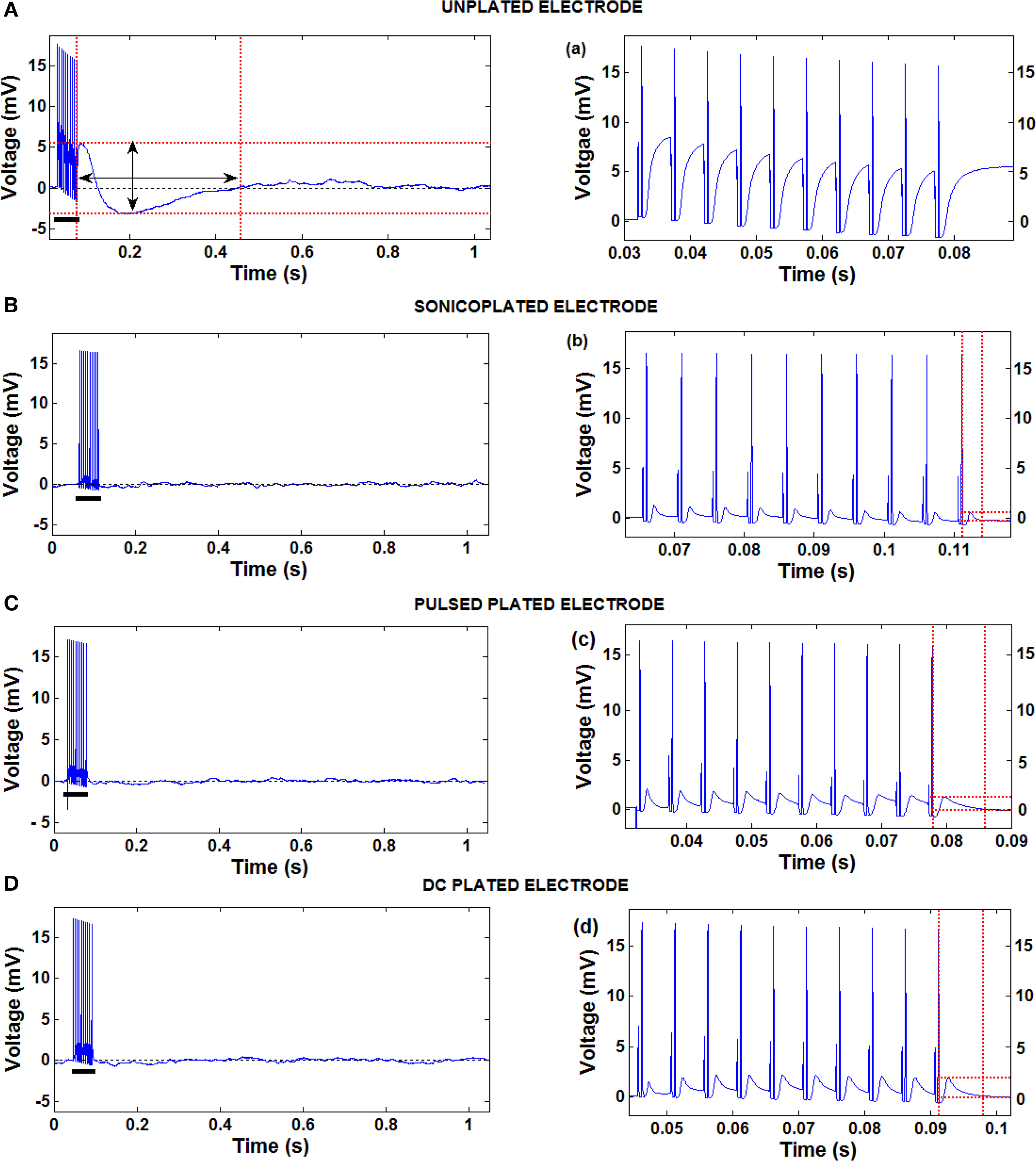
Figure 7. Stimulation artifacts on electrodes produced by a pulse train of ten 10-μA, 800-μs pulses on the same electrode. (A–D) Stimulation artifacts on one each of the three types of plated and the unplated electrodes. (a–d) Zoomed in recordings of the high frequency part of the stimulation artifacts of the respective images on the left (shown with black bars). The dotted red lines show the amplitude and duration of the stimulation artifacts. Amplitude of the stimulation artifact was measured as the difference between the local maxima and local minima following the last pulse delivered. Duration was measured as the time between the last pulse delivered and the time for the voltage to return to 1% of the baseline voltage. The pulses are clipped at 18 mV due to the limitations of our recording system.
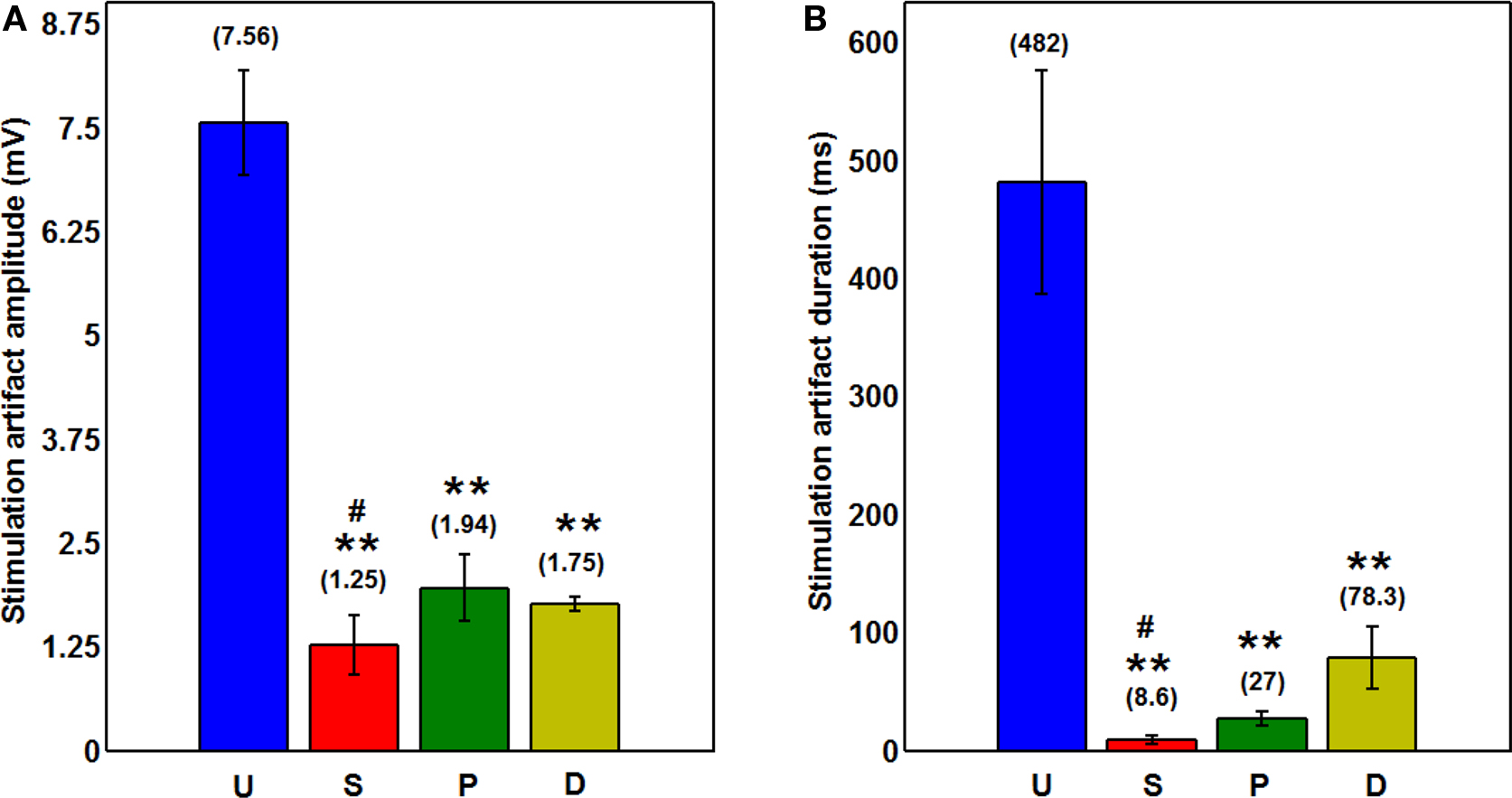
Figure 8. (A) Amplitude of the stimulation artifact on the three types of plated and unplated electrodes after ten 10-μs pulses are delivered. Mean ± standard error values on the four electrodes of each type of plating are shown graphically. Values in parentheses show the mean.**p < 0.005 compared to unplated electrodes; #p < 0.27 compared to pulsed plated and DC plated electrodes. (B) Duration of the stimulation artifacts with mean in parentheses and error bars showing standard error.**p < 0.01 compared to unplated electrodes; #p < 0.07 compared to pulsed plated and sonicoplated electrodes.
Thermal or Johnson-Nyquist Noise
Thermal noise is the electronic noise generated by the thermal agitation of the charge carriers (usually electrons) inside an electrical conductor at equilibrium, which happens regardless of any applied voltage and depends on the electrode impedance. Thermal noise is commonly believed to be one of the main contributors to noise in MEA recordings (Heuschkel et al., 2002 ).
Thermal noise is quantified by the formula

where v is the noise amplitude (in units of volts per √Hz), kB is Boltzmann’s constant, T is the temperature, and Z is the impedance. Hence, noise varies with the square root of the impedance of the electrode. So, decreasing the impedance of the electrodes should decrease the thermal noise. We made a spontaneous recording on an unplated electrode in an awake and behaving rat and compared this with recordings on the same electrode made after the animal was euthanized by an injection of euthasol. Our intention was to eliminate all biological sources of noise while keeping the physical environment surrounding the electrode constant. We observed an action-potential free recording on an unplated electrode to have an RMS amplitude of about 120 μV in an awake and behaving animal (The RMS includes frequencies in the 1 Hz to 9 kHz range). We also noticed that movement artifacts don’t contribute much to recorded activity.
A continuous recording was made before and after a lethal dose of euthasol. Figure 9 A shows brain activity ceasing ∼13 min post injection. At this time, the total noise recorded on the same unplated electrode had an RMS amplitude of about 9 μV. Because brain activity ceases within 13 min after circulation ceases, it can be safely assumed that most of the 9 μV noise observed is thermal noise and noise due to electromagnetic interference (EMI).
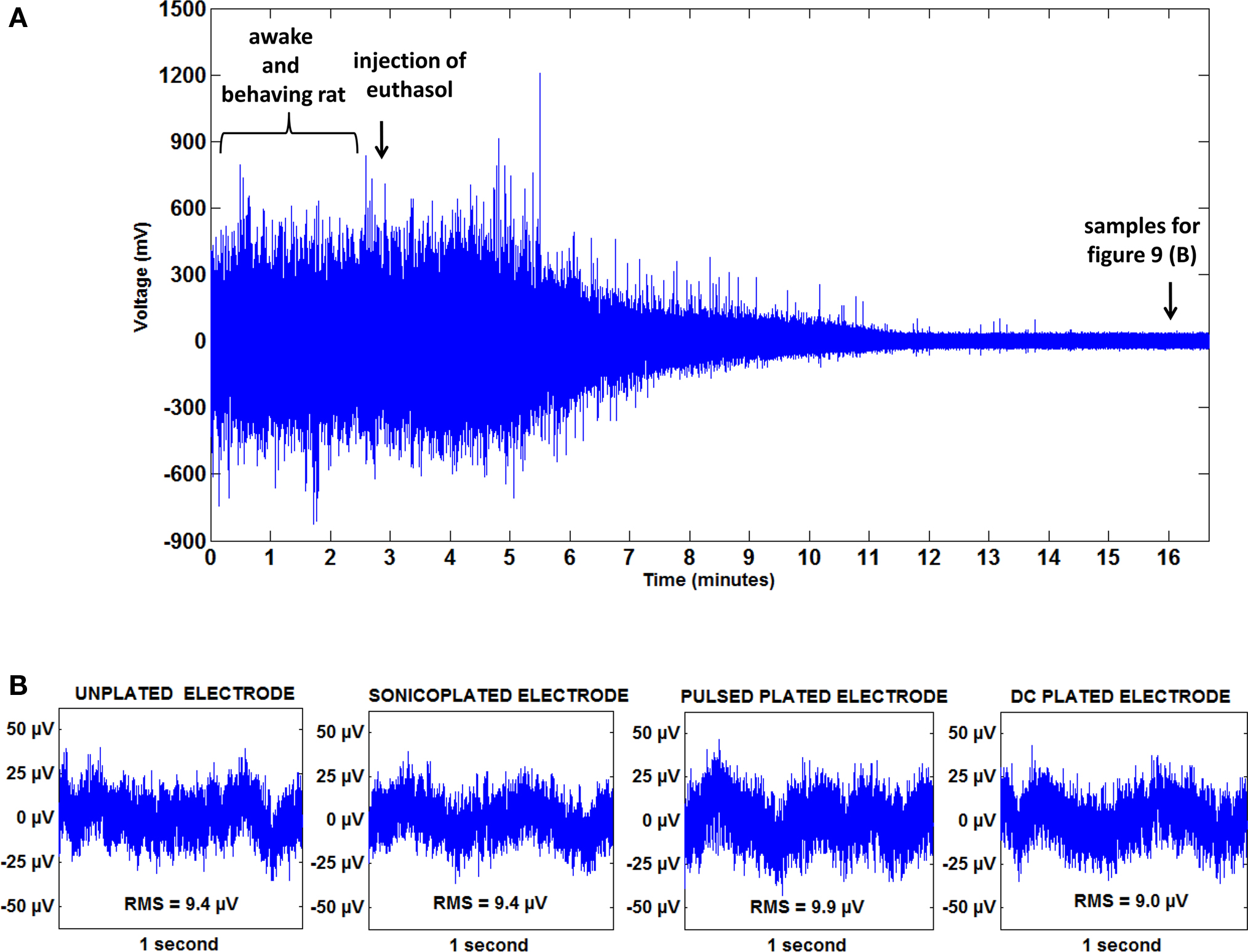
Figure 9. Thermal noise and EMI together contribute less than 10% of the total noise in an in vivo recording (A) A 17 min recording from a rat on an unplated electrode showing the cessation of neural activity after an injection of euthasol. (B) (L–R) recording on an unplated, sonicoplated, pulsed plated and DC plated electrode in a euthanized rat. Mean RMS noise levels on the three types of plated and unplated electrodes are shown below the respective plots. No significant difference (0.3 < p < 0.6) is seen in the noise levels on the three types of plated and unplated electrodes.
Hence, thermal noise and EMI together contribute less than 10% to the total noise. We compared noise levels on the three types of plated electrodes and the unplated electrodes in a euthanized animal (Figure 9 B). As can be seen from the figure, there is no significant difference (0.3 < p < 0.6) between the noise levels on the different types of plated and unplated electrodes in a euthanized animal, showing that a decrease in thermal noise levels is not measurable and may be obscured by noise from EMI.
Discussion and Conclusion
We have introduced and characterized the technique of sonicoplating (plating under ultrasonic agitation) of Pt black on MMEAs for increased durability compared to traditional plating techniques.
A test for durability was performed by subjecting MMEAs (whose electrode impedances were reduced to the same extent by the sonicoplating method and the traditional DC and pulsed plating methods) to an hour of ultrasonic agitation in a standard saline solution. Sonicoplated electrodes were able to withstand this durability test much better than those plated by the other two methods. Improved durability is important, especially in chronic studies, where it is required to record or stimulate in the same regions of the brain sometimes even over the period of a few months. Even in acute studies, the plating has to be durable enough to withstand the process of being implanted into the brain, penetrating through pia mater and brain tissue. Poor durability has been one of the main reasons why Pt black-plated MEAs are seldom used.
Lowering impedance on MMEAs has a direct effect on lowering the required stimulation voltage in current controlled stimulations. This can have two important consequences. Firstly, reduced voltage while stimulating would mean less power is dissipated in the brain in the form of heat, leading to less tissue damage (power is directly proportional to electrode impedance). This can be of great practical importance for experiments or therapeutic treatments requiring persistent or high-frequency stimulation. Secondly, since stimulation voltage is reduced by this method, stimuli are less likely to exceed the water window that occurs at voltages of above 1 V (at which oxidation of the electrode begins) or below −0.8 V (at which hydrogen evolution begins) (Rozman et al., 2000 ) causing the irreversible breakdown of water into O2 and H2 gases (Merrill et al., 2005 ). Hence, lowering impedance will increase the range of currents that one can use without hitting the water window and causing irreversible electrolytic damage in the brain.
Stimulation artifacts result because of charge accumulation in the interface between the electrodes and the surrounding tissue immediately after stimulation. These artifacts can often last 500 ms or even longer (Figure 8 ) and have amplitudes that are more than ten times the amplitude of physiological action potentials, making spike detection difficult or even impossible immediately after stimulation. Evoked responses can occur in as little as 1 ms after a stimulation (Wagenaar and Potter, 2002 ; Rolston et al., 2009 ), hence it is important to reduce the duration of stimulation artifacts to as short as possible. A substantial reduction in the electrode impedance can greatly reduce the problem of stimulation artifacts. Since sonicoplating of Pt black maintains low impedance values for long periods of time, this technique helps get rid of stimulation artifacts, potentially making spike detection possible even a few milliseconds after stimulation on the stimulating electrode (Figure 8 ), and even sooner on non-stimulation electrodes.
Thermal noise or Johnson-Nyquist noise, electromagnetic interference (EMI) from nearby electronics and biological signals of no interest to the investigator are believed to be the main contributors to noise in neural recordings. We have shown that contributions from thermal noise and electromagnetic interference make up less than 10% of the total noise when using electrodes with typical microwire impedances and that no significant reduction in thermal and EMI noise is observed with lowered impedances. Hence, a reduction in the thermal noise (if any) is obscured by effects from EMI.
This is only the first basic analysis of the benefits of sonicoplating for chronic MMEAs. Similar sonicoplating techniques that Potter and Pine developed in the mid 1990s have proven useful for recording or stimulating cultured networks using planar MEAs in vitro (Pancrazio et al., 1998 ; Maher et al., 1999 ; Ross et al., 2004 ). We continued to record action potentials from our longest-living cortical culture (Potter and DeMarse, 2001 ) for well over a year, from MEA electrodes that were sonicoplated. One study demonstrated the efficacy of a sonicoplated polyimide sieve electrode at recording and stimulating re-grown peripheral nerves, weeks after implantation (Ramachandran et al., 2006 ). However, they did not conduct an analysis of the long-term effects of sonication on the Pt coatings used. It is likely that sonicoplating can be extended to other high-surface-area conductive coatings than Pt black, for example, conductive polymers like PEDOT, which are also electrodeposited (Xiao et al., 2004 ).
As more closed-loop applications are used, in the laboratory and in the clinic (Arsiero et al., 2007 ), the ability to both stimulate and record from the same or nearby electrodes becomes more urgent. Sonicoplating can help overcome one hurdle for such stimulate-record applications, the stimulation artifact.
Since it has now proven useful on cyclic voltammetry electrodes, multiwire MEAs, polyimide sieve electrodes, and planar MEAs, it is likely that sonicoplating will be generally applicable to all electrode types in which a durable reduction in impedance is desirable. This may also include macroelectrodes used for deep brain stimulation (Gross et al., 2004 ).
Conflict of Interest Statement
The authors declare that this research was conducted in the absence of any commercial or financial relationships that could be construed as a potential conflict of interest.
Acknowledgments
This work was funded by the Wallace H. Coulter Foundation, an NIH Grant (NS05480) and an NSF EFRI COPN Grant (0836017). The authors wish to thank Dr. Robert E. Gross for providing resources related to animal work carried out in this paper.
References
Arsiero, M., Luscher, H. R., and Giugliano, M. (2007). Real-time closed-loop electrophysiology: towards new frontiers in in vitro investigations in the neurosciences. Arch. Ital. Biol. 145, 193–209.
Branner, A., Stein, R. B., and Normann, R. A. (2001). Selective stimulation of cat sciatic nerve using an array of varying-length microelectrodes. J. Neurophysiol. 85, 1585–1594.
Cogan, S. F. (2008). Neural stimulation and recording electrodes. Annu. Rev. Biomed. Eng. 10, 275–309.
Deadwyler, S. A., and Hampson, R. E. (2004). Differential but complementary mnemonic functions of the hippocampus and subiculum. Neuron 42, 465–476.
Dymond, A. M., Kaechele, L. E., Jurist, J. M., and Crandall, P. H. (1970). Brain tissue reaction to some chronically implanted metals. J. Neurosurg. 33:574–580.
Ganguly, K., Secundo, L., Ranade, G., Orsborn, A., Chang, E. F., Dimitrov, D. F., Wallis, J. D., Barbaro, N. M., Knight, R. T., and Carmena, J. M. (2009). Cortical representation of ipsilateral arm movements in monkey and man. J. Neurosci. 29, 12948–12956.
Gladstein, M., and Guterman, H. (2001). A novel method of controlling metal deposition during a pulse plating process. Plating Surf. Finishing 88, 78–79.
Gladstein, M., and Guterman, H. (2005). A new method of current density control during the pulse plating process. Trans. Inst. Met. Finishing 83, 148–153.
Gross, R. E., Jones, E. G., Dostrovsky, J. O., Bergeron, C., Lang, A. E., and Lozano, A. M. (2004). Histological analysis of the location of effective thalamic stimulation for tremor – Case report. J. Neurosurg. 100, 547–552.
Heuschkel, M. O., Fejtl, M., Raggenbass, M., Bertrand, D., and Renaud, P. (2002). A three-dimensional multi-electrode array for multi-site stimulation and recording in acute brain slices. J. Neurosci. Methods 114, 135–148.
Maher, M. P., Pine, J., Wright, J., and Tai, Y. C. (1999). The neurochip: a new multielectrode device for stimulating and recording from cultured neurons. J. Neurosci. Methods 87, 45–56.
Marrese, C. A. (1987). Preparation of strongly adherent platinum black coatings. Anal. Chem. 59, 217–218.
McCreery, D., Lossinsky, A., Pikov, V., and Liu, X. D. (2006). Microelectrode array for chronic deep-brain micro stimulation and recording. IEEE Trans. Biomed. Eng. 53, 726–737.
Merrill, D. R., Bikson, M., and Jefferys, J. G. R. (2005). Electrical stimulation of excitable tissue: design of efficacious and safe protocols. J. Neurosci. Methods 141, 171–198.
Nicolelis, M. A. L., Ghazanfar, A. A., Faggin, B. M., Votaw, S., and Oliveira, L. M. O. (1997). Reconstructing the engram: Simultaneous, multisite, many single neuron recordings. Neuron 18, 529–537.
O’Doherty, J. E., Lebedev, M. A., Hanson, T. L., Fitzsimmons, N. A., and Nicolelis, M. A. (2009). A brain-machine interface instructed by direct intracortical microstimulation. Front. Integr. Neurosci. 3, 20. doi:10.3389/neuro.07.020.2009.
Pancrazio, J. J., Bey, P. P., Loloee, A., Manne, S. R., Chao, H. C., Howard, L. L., Gosney, W. M., Borkholder, D. A., Kovacs, G. T. A., Manos, P., Cuttino, D. S., and Stenger, D. A. (1998). Description and demonstration of a CMOS amplifier-based-system with measurement and stimulation capability for bioelectrical signal transduction. Biosens Bioelectron 13, 971–979.
Polikov, V. S., Tresco, P. A., and Reichert, W. M. (2005). Response of brain tissue to chronically implanted neural electrodes. J. Neurosci. Methods 148, 1–18.
Potter, S. M., and DeMarse, T. B. (2001). A new approach to neural cell culture for long-term studies. J. Neurosci. Methods 110, 17–24.
Quiroga, R. Q., Nadasdy, Z., and Ben-Shaul, Y. (2004). Unsupervised spike detection and sorting with wavelets and superparamagnetic clustering. Neural. Comput. 16, 1661–1687.
Ramachandran, A., Schuettler, M., Lago, N., Doerge, T., Koch, K. P., Navarro, X., Hoffmann, K. P., and Stieglitz, T. (2006). Design, in vitro and in vivo assessment of a multi-channel sieve electrode with integrated multiplexer. J. Neural Eng. 3, 114–124.
Rolston, J. D., Gross, R. E., and Potter, S. M. (2009). A low-cost multielectrode system for data acquisition enabling real-time closed-loop processing with rapid recovery from stimulation artifacts. Front. Neuroengineering 2, 12. doi: 10.3389/neuro.16.012.2009.
Rose, T. L., and Robblee, L. S. (1990). Electrical-stimulation with pt electrodes.8. electrochemically safe charge injection limits with 0.2 ms pulses. IEEE Trans. Biomed. Eng. 37, 1118–1120.
Ross, J. D., O’Connor, S. M., Blum, R. A., Brown, E. A., and DeWeerth, S. P. (2004). Multielectrode impedance tuning: reducing noise and improving stimulation efficacy. Conference Proceedings 26th Annual International Conference of the IEEE Engineering in Medicine and Biology Society (IEEE Cat No04CH37558) 4115-4117 Vol.4116|4117 vol. (lxxxvii + 5459).
Rozman, J., Milosev, I., and Jenko, M. (2000). Platinum stimulating electrodes in physiological media. J. Med. Eng. Technol. 24, 123–128.
Rudge, J. S., Smith, G. M., and Silver, J. (1989). An invitro model of wound-healing in the CNS - Analysis of cell reaction and interaction at different ages. Exp. Neurol. 103, 1–16.
Shi, L. H., Luo, F., Woodward, D. J., McIntyre, D. C., and Chang, J. Y. (2007). Temporal sequence of ictal discharges propagation in the corticolimbic basal ganglia system during amygdala kindled seizures in freely moving rats. Epilepsy Res. 73, 85–97.
Venkatraman, S., Elkabany, K., Long, J. D., Yao, Y. M., and Carmena, J. M. (2009). A system for neural recording and closed-loop intracortical microstimulation in awake rodents. IEEE Trans. Biomed. Eng. 56, 15–22.
Vetter, R. J., Williams, J. C., Hetke, J. F., Nunamaker, E. A., and Kipke, D. R. (2004). Chronic neural recording using silicon-substrate microelectrode arrays implanted in cerebral cortex. IEEE Trans Biomed Eng 51, 896–904.
Wagenaar, D. A., and Potter, S. M. (2002). Real-time multi-channel stimulus artifact suppression by local curve fitting. J. Neurosci. Methods 120, 113–120.
Keywords: microelectrode arrays, impedance, platinum black, electroplating, stimulation artifact, thermal noise
Citation: Desai SA, Rolston JD, Guo L and Potter SM (2010) Improving impedance of implantable microwire multi-electrode arrays by ultrasonic electroplating of durable platinum black. Front. Neuroeng. 3:5. doi: 10.3389/fneng.2010.00005
Received: 25 December 2009;
Paper pending published: 25 March 2010;
Accepted: 07 April 2010;
Published online: 06 May 2010
Edited by:
Martin Stelzle, University of Tübingen, GermanyReviewed by:
Claus Burkhardt, University of Tübingen, GermanyDirk Jansen, University of Offenburg, Germany
Copyright: © 2010 Desai, Rolston, Guo and Potter. This is an open-access article subject to an exclusive license agreement between the authors and the Frontiers Research Foundation, which permits unrestricted use, distribution, and reproduction in any medium, provided the original authors and source are credited.
*Correspondence: Steve M. Potter, Laboratory for Neuroengineering, The Wallace H. Coulter Department of Biomedical Engineering, Georgia Institute of Technology, 313 Ferst Dr. NW, Atlanta, GA 30332-0535, USA. e-mail:c3RldmUucG90dGVyQGJtZS5nYXRlY2guZWR1