 Yuyan Wu
 Hae Young Noh
- Department of Civil and Environmental Engineering, Stanford University, Stanford, CA, United States
Introduction: Detecting road boundaries, the static physical edges of the available driving area, is important for safe navigation and effective path planning in autonomous driving and advanced driver-assistance systems. Traditionally, road boundary detection in autonomous driving relies on cameras and LiDAR. However, they are vulnerable to poor lighting conditions, such as nighttime and direct sunlight glare, or prohibitively expensive for low-end vehicles.
Methods: This paper introduces 4DRadarRBD, the first road boundary curve detection method based on 4D mmWave radar, which is cost-effective and robust in complex driving scenarios. The main idea is that road boundaries (e.g., fences, bushes, roadblocks) reflect millimeter waves, thus generating point cloud data for the radar. To overcome the challenge that the 4D mmWave radar point clouds contain many noisy points, we initially reduce noisy points via physical constraints for road boundaries and then segment the road boundary points from the noisy points by incorporating a distance-based loss which penalizes for falsely detecting the points far away from the actual road boundaries. In addition, we capture the temporal dynamics of point cloud sequences by utilizing each point’s deviation from the vehicle motion-compensated road boundary detection result obtained from the previous frame, along with the spatial distribution of the point cloud for point-wise road boundary segmentation.
Results: We evaluated 4DRadarRBD through real-world driving tests and achieved a road boundary point segmentation accuracy of 93%, with a median distance error of up to 0.023 m and an error reduction of 92.6% compared to the baseline model.
1 Introduction
Road boundary detection is important for autonomous driving and advanced driver-assistance systems to prevent collisions. Road boundaries are the static physical edges of drivable areas, including fences, bushes, and roadblocks, beyond which there is a risk of collision. Road boundary detection helps reduce the risk of collisions and allows navigation systems to maintain a safe distance from the road boundary in autonomous driving.
Current sensing methods for road boundary detection mainly include RGB cameras and LiDAR Sun et al. (2019); Kang et al. (2012); Zhang et al. (2015); Chen and Chen (2017); Wen et al. (2008); Taher et al. (2018). However, RGB cameras lack depth perception and struggle in poor lighting conditions, such as nighttime and direct sunlight glare. LiDAR provides accurate distance information but is costly and impractical for lower-end vehicles. Thus, autonomous driving systems require a cost-effective and robust road boundary detection method that performs reliably across various lighting conditions.
This paper introduces 4DRadarRBD, the first 4D mmWave radar-based road boundary curve detection system, which is cost-effective and robust for complex driving scenarios. The main idea of the system is that the radar emits millimeter waves, which get reflected by road boundaries (e.g., fences, bushes, and roadblocks). These reflections are captured as point clouds, which are then used to detect the road boundaries. Unlike 3D mmWave radar, which estimates range, azimuth, and Doppler velocity, 4D mmWave radar introduces elevation measurement, significantly enhancing its ability to differentiate between various objects. The inclusion of elevation data allows the radar to more accurately identify whether an object is an overhead structure that can be safely passed beneath or a road boundary that requires maintaining a safe distance.
However, there are two main challenges for road boundary detection using 4D mmWave radar. Firstly, in complex driving environments, the 4D mmWave radar point cloud contains a large number of noisy points from non-road boundary objects (e.g., vehicles, overpasses) and random ghost points. Secondly, it is difficult to capture the temporal dynamics of the point cloud sequences with the fast vehicle movement (up to 30 m/s) and the low radar sampling rate (
4DRadarRBD addresses these challenges and achieves road boundary detection with three modules. In the first module, the point cloud is preprocessed to extract point-wise features, reduce noise using physical constraints, and mitigate point cloud sparsity through frame fusion. In the second module, we segment the road boundary points from the noisy points and capture the temporal dynamics of the point cloud. Finally, the third module fits road boundary curves based on the segmented road boundary points, providing continuous road boundary estimates for control and planning tasks. The first challenge is addressed by first utilizing the physical constraints of the road boundary to reduce noisy points in the first module and then incorporating a distance-based loss to penalize points far away from the road boundary for being detected as road boundaries in the second module. To solve the second challenge, we capture the temporal dynamics of point cloud sequences with the deviation of each point in the current frame from the motion-compensated road boundary points of the previous frame. The deviation is incorporated as a feature in the point cloud segmentation framework in the second module, improving temporal consistency in road boundary detection.
The main contributions of 4DRadarRBD consist of:
• We introduce 4DRadarRBD, the first 4D mmWave radar-based road boundary curve detection system, which is cost-efficient and robust to complex driving scenarios.
• We mitigate the effects of noisy points and capture the temporal dynamics of point cloud sequences for robust road boundary detection.
• We evaluate the 4DRadarRBD system through real-world driving tests in complex scenarios and achieve accurate and robust road boundary detection results.
2 Related works
LiDAR and RGB cameras are mainly used for road boundary detection in autonomous driving. LiDAR systems provide high-resolution three-dimensional point clouds of the driving environment Medina and Paffenroth (2021); Sun et al. (2019), which contain rich environmental information, enabling effective road boundary detection. However, LiDAR sensors are expensive and not feasible for widespread deployment, particularly in low-cost vehicles. RGB cameras are widely used for road boundary detection due to their affordability and wide availability in autonomous vehicles Chen and Chen (2017); Wen et al. (2008); Taher et al. (2018). Cameras capture extensive environmental details to identify lane markings, road edges, and barriers. Nonetheless, cameras are vulnerable to occlusions from dirt and perform poorly under challenging lighting and weather conditions, such as nighttime or fog.
Previous studies have made preliminary attempts at mmWave radar-based road boundary detection methods Xu et al. (2020); Kingery and Song (2024); Patel and Elgazzar (2022); Guo et al. (2014); Patel and Elgazzar (2024); Mandlik et al. (2021); Popov et al. (2022). Xu et al. (2020); Kingery and Song (2024); Guo et al. (2014) employ RANSAC or Hough Transform algorithms to fit parametric curves representing road boundaries. However, these techniques rely on predefined curve models, limiting their robustness in complex or irregular boundary geometries. Other studies treat road boundary detection as a free-space segmentation task, generating bird’s-eye-view (BEV) maps that delineate drivable areas Popov et al. (2022); Liu et al. (2024); Southcott et al. (2023); Li et al. (2018). This formulation is flexible to diverse boundary shapes but often results in abrupt frame-to-frame temporal inconsistencies. Mandlik et al. (2021) addresses both arbitrary geometries and temporal consistency by maintaining a point cloud buffer of previous frames. Nonetheless, it provides the road boundary detection results as disconnected short line segments rather than continuous boundary curves, which limits its ability to reconstruct complete boundaries for downstream path-planning tasks. Therefore, a robust method is needed that accommodates diverse boundary geometries and captures the temporal dynamics of mmWave radar point clouds, providing smooth and consistent road boundary curve estimation for downstream path planning in real-world driving scenarios.
In the road boundary point segmentation module, 4DRadarRBD uses the PointNet++ structure, a point-based segmentation method suitable for the sparse 4D point cloud generated by 4D mmWave radar. Point cloud segmentation methods fall into three categories: point-based Zhu et al. (2021); Zhang et al. (2022); Wu et al. (2019), voxel-based He et al. (2021); Park et al. (2023), and projection-based Lang et al. (2019); Sun et al. (2024). Point-based methods, like PointNet++, directly use point cloud data as input. Voxel-based methods convert point clouds into a 3D voxel grid, enabling the use of 3D CNNs to learn spatial features. Projection-based methods transform 3D point clouds into depth images or 2D projections, allowing for standard 2D CNNs. While voxel-based and projection-based methods are good at capturing spatial details, they are less effective for sparse 4D mmWave point clouds, often resulting in many empty voxels or pixels at greater distances. Point-based methods, which directly process point clouds without altering their structure, are better suited for our road boundary segmentation task. Therefore, a point-based framework is used for road boundary segmentation.
3 4DRadarRBD system
In this section, we introduce the 4DRadarRBD system which detects road boundaries using point cloud data from 4D mmWave radar. The system mainly includes three modules: 1) point cloud preprocessing, 2) point-wise road boundary segmentation, and 3) curve-wise road boundary shape fitting (see Figure 1).
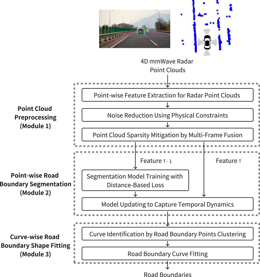
Figure 1. 4DRadarRBD system overview.
3.1 Module 1: Point cloud preprocessing
We first preprocess the point cloud obtained from 4D mmWave radar to extract point-wise features for the road boundary segmentation task while reducing noisy points and mitigating the sparsity of the point cloud.
3.1.1 Point-wise feature extraction for radar point clouds
The point-wise features of the point cloud are extracted from 4D mmWave radar signals and onboard sensors (GPS, IMU), including position coordinates (x, y, z), Doppler velocity, signal-to-noise ratio, range, vehicle velocity, and yaw rate. Among them, the first four features are derived from 4D mmWave radar, while vehicle velocity and yaw rate are obtained from GPS and IMU sensors. The position (x, y, z) is defined with respect to a coordinate system originating at the location of 4D mmWave radar, which is typically mounted near the front license plate of the vehicle. In this coordinate system, the x-axis extends to the right-hand side of the vehicle, the y-axis points forward along the vehicle’s driving direction, and the z-axis points upward. Position and range indicate the object’s location, while the signal-to-noise ratio provides insight into the material and surface properties of the object. Additionally, vehicle speed, yaw rate, and Doppler velocity collectively describe the object’s motion. These features contain critical information about the object reflecting millimeter waves and are important for accurately segmenting road boundary points.
3.1.2 Noise reduction using physical constraints
We apply physical constraints to filter out noisy points by excluding those that exceed the expected height or velocity range of static road boundaries. Since 4DRadarRBD is designed for standard vehicles, which typically do not exceed 3 m in height, points above 3 m (typically from overhead structures such as streetlights or overpasses) are excluded to reduce noise. Additionally, given typical mmWave radar mounting heights of 0.6–1.2 m above the ground, points below −1.5 m are filtered as they likely result from elevation measurement instability or multipath artifacts (ghost points). To further reduce noisy points, velocity-based filtering is applied to eliminate the points whose Doppler velocity significantly deviates from that of static road boundaries. Since road boundaries are stationary, points with substantial motion are unlikely to represent valid boundary detections. The velocity deviation is calculated as the difference between the measured Doppler velocity of a point and the expected Doppler velocity of a static object at the same position, derived from the vehicle’s velocity. Points with a deviation exceeding 1 m/s are excluded as noisy points. This threshold value is selected to compensate for uncertainties in Doppler velocity and azimuth measurements while effectively rejecting slow-moving vehicles. As shown in Figure 2, this filtering effectively removes noisy points, enhancing the clarity and detectability of road boundary features. The distance loss is particularly high for these false positive points, which helps mitigate the false positive detections. By jointly optimizing the BCE and distance losses (see Equation 2), the network effectively mitigates false-positive detections and enhances the robustness of boundary segmentation.
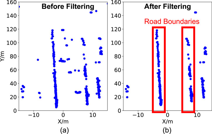
Figure 2. Comparison of point cloud data before and after filtering. (a) Raw data includes points from moving vehicles and street signs within the roadway. (b) After applying noise reduction based on physical constraints, non-road features are removed, enhancing the clarity of road boundary points.
3.1.3 Point cloud sparsity mitigation by multi-frame fusion
To mitigate the sparsity of the 4D mmWave radar point cloud, we fuse point clouds from three consecutive frames. First, we apply motion compensation by transforming the point cloud data from previous frames into the world coordinate system and then converting it back to the self-coordinate system of the current frame. The necessary transformation and rotation matrices for this conversion are obtained from the vehicle’s GPS sensor. In addition, during the fusion process, we introduce an index in the point-wise features to indicate the frame origin of each point: 0 for the current frame, 1 for the previous frame, and 2 for the frame before that. This index preserves temporal information for road boundary segmentation task.
3.2 Module 2: Point-wise road boundary segmentation
The point-wise road boundary segmentation module aims to distinguish road boundary points from noisy points. The segmentation is based on the PointNet++ framework, which efficiently captures the spatial distribution of point clouds and point-wise features Qi et al. (2017). The main innovations of our method are: 1) we reduce the false positive detections (i.e., falsely detecting non-road boundary points) by incorporating a distance-based loss, which penalizes detected points far away from the road boundary as road boundaries into the PointNet++ segmentation network and 2) we capture the temporal dynamics of the point cloud sequences by adding the vector representing point’s deviation from the motion-compensated road boundary detection result obtained from the previous frame into the point-wise features.
3.2.1 Segmentation model training with distance-based loss
To reduce false positive detections of noisy points, we incorporate a distance-based loss into the PointNet++ segmentation network to penalize such false positive detections. The PointNet++ network is selected as the basic structure of the point segmentation module due to its effectiveness in extracting hierarchical features and its adaptability to various spatial scales Qi et al. (2017). The original PointNet++ network uses only binary cross-entropy loss for point segmentation, which is inadequate for our task. This limitation arises because, after point cloud preprocessing, most noisy points are filtered out, leaving only a small fraction of distant noisy points compared to road boundary points. Consequently, their influence on the loss function is minimal. However, if these distant noisy points are misclassified as road boundary points (false positive detections), they can significantly degrade the boundary fitting process. To this end, we calculate the average Euclidean distance between each detected road boundary point and its nearest actual road boundary point as the distance loss (see Figure 3a). The distance loss is defined in Equation 1. Here,
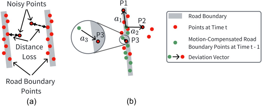
Figure 3. (a) Distance loss is calculated as the Euclidean distance between the detected and the actual road boundary points, which has a large value for the noisy points far away from the road boundaries; (b) The deviation vectors for each point in the current frame (e.g.,
3.2.2 Model updating to capture temporal dynamics
To capture the temporal dynamics of the point cloud sequences, we augment each point’s feature representation with a deviation vector, which encodes its direction and distance relative to the road boundary points detected in the previous frame. For each point in the current frame, this deviation vector is defined as the shortest vector originating from a motion-compensated road boundary point in the previous frame and terminating at the current point (see Figure 3b). P1, P2, and P3, along with their respective deviation vectors
Additionally, we incorporate the road boundary probability of the closest detected road boundary point from the previous frame (the starting point of the deviation vector) as a point-wise feature. This probability serves as a confidence measure in road boundary segmentation process. Without this confidence information, if a noisy point far away from the road boundaries is mistakenly detected as a road boundary point in one frame, it can lead to error propagation in subsequent frames. However, we observe that in such cases, incorrectly detected points generally have a lower road boundary probability than actual boundary points, indicating lower confidence in the segmentation result. By incorporating this probability, the model gains confidence awareness, effectively suppressing the propagation of false detections across frames.
3.3 Module 3: Curve-wise road boundary shape fitting
Point-wise road boundary segmentation only provides discrete points representing road boundaries. However, control and planning tasks in autonomous driving usually require continuous road boundary curves. To this end, we first identify the continuous curves from the detected road boundary points by clustering, and then fit the road boundary curves for each of the identified point cloud clusters.
3.3.1 Curve identification by road boundary points clustering
We employ the DBSCAN clustering method Ester et al. (1996) to identify continuous road boundary curves from the detected road boundary points. DBSCAN is chosen because it does not require a predefined number of clusters, which is suitable for situations where the number of road boundaries is uncertain. It is also capable of clustering road boundaries of various shapes, which is crucial in complex driving scenarios. Due to the short Euclidean distance between the left and right road boundaries, the algorithm often incorrectly clusters them into one cluster. To solve this problem, we divide the y-coordinate (representing the forward direction of vehicle motion) of the point cloud by a factor before clustering. This scaling factor is set to 5 based on empirical analysis of point cloud sparsity, which balances the trade-off between boundary fragmentation and over-merging. Smaller factors result in over-segmentation due to point sparsity, while factors exceeding 5 cause incorrect merging of opposite-side boundaries at intersections. Since road boundaries usually follow the direction of vehicle motion, this scaling helps the algorithm better cluster the road boundary curves. Without this scaling, the algorithm may incorrectly cluster left- and right-parallel road boundary curves into a single cluster due to their close Euclidean distance or split a single road boundary into multiple clusters due to the variation in the distance along the y-axis.
3.3.2 Road boundary curve fitting
We take subsamples from each cluster identified by the DBSCAN algorithm and use Gaussian Process Regression (GPR) to fit road boundary curves and provide 95
4 Evaluation with real-world driving test
We conducted a real-world driving test and collected a dataset comprising 30,424 frames of 4D mmWave radar point clouds from Changping District, China, for field evaluation.
4.1 Driving test and dataset description
The real-world driving dataset consists of 50 data clips, each approximately 40 s in duration, totaling 30,424 frames. During the driving tests, RGB cameras, 4D millimeter-wave (mmWave) radar, LiDAR, GPS, and IMU sensors are used to capture detailed driving scenario information. The 4D mmWave radar used in this study operates in a dual-band mode covering 76–79 GHz, comprising both long-range (76–77 GHz) and short-range (77–79 GHz) channels. The long-range channel provides extended detection capability with a narrower bandwidth, while the short-range channel offers higher resolution for near-field sensing. The horizontal field of view (FoV) of the radar is
4.2 Performance evaluation metrics
We evaluate the 4DRadarRBD system using point-wise road boundary segmentation accuracy, Chamfer distance (CD) error, and Hausdorff distance (HD) error between the detected and actual road boundaries. Chamfer distance and Hausdorff distance are calculated as the average and maximum closest point distance, respectively, between the sets of detected and actual road boundary points Borgefors (1986); Rockafellar and Wets (2009).
4.3 Evaluation results and ablation study
4DRadarRBD achieves 93
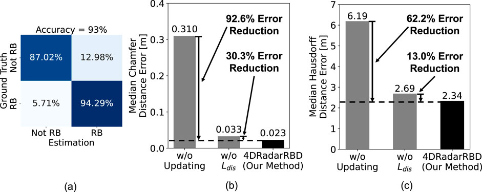
Figure 4. Overall Performance of 4DRadarRBD. (a) Confusion matrix for road boundary (RB) point segmentation (accuracy = 93
To evaluate the effectiveness of 4DRadarRBD, two ablation tests are conducted, including: 1) using the model without updating with the deviation vector obtained from the previous frame’s detection results (baseline model) and 2) using the model trained without the incorporation of distance loss. All model architectures, training procedures, and hyperparameters remain identical to our method except for the specified ablations. By updating the model with the deviation vector, 4DRadarRBD reduces the median Chamfer distance error by 92.6
4.4 Evaluation of system robustness
In this section, we evaluate the robustness of the 4DRadarRBD system to varying numbers of road boundary curves, varying types of noisy points, varying road boundary curve shapes, and the system’s temporal stability over driving time.
4.4.1 Effect of varying numbers of road boundary curves
4DRadarRBD is robust to varying numbers of road boundary curves. Figure 5 shows the road boundary detection results for three typical complex driving scenarios, including a highway situation with 2 road boundary curves (top), a fork road situation with 3 road boundary curves (middle), and a complex urban area situation with multiple road boundary curves (bottom). The left figures show the top view of the point cloud and the corresponding detection results, with the red dots representing the detected road boundary points and the blue dots representing the detected non-road boundary points. The right figures represent the corresponding RGB images. The 4DRadarRBD system can automatically detect varying numbers of road boundary curves and accurately fit the road boundary curves. Notably, in the third scenario, 4DRadarRBD successfully separates the two road boundary curves at the intersection instead of connecting them.
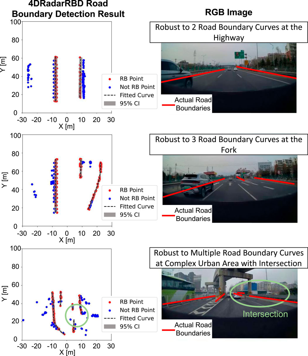
Figure 5. 4DRadarRBD successfully detects road boundaries (referred to as RB) with varying numbers of road boundary curves in: a simple scenario with two curves (top), a forked road intersection with three curves (middle), and a complex urban environment with multiple curves (bottom). In the complex urban area, 4DRadarRBD successfully detects the intersection.
4.4.2 Effect of noisy points in complex driving scenario
The 4DRadarRBD system successfully achieves robust road boundary detection with various environmental noisy points. On a highway with multiple overpasses and moving vehicles, we achieve up to 94
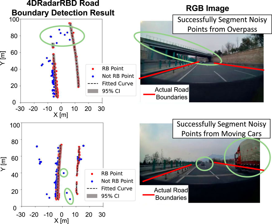
Figure 6. 4DRadarRBD successfully segments road boundary (RB) points with the noisy points from overpasses and moving vehicles, proving its robustness in complex driving scenarios.
4.4.3 Effect of road boundary curve shapes
4DRadarRBD is robust to various shapes of road boundary curves. Under the twisting driving conditions of mountainous roads, we achieve a point-wise road boundary segmentation accuracy as high as 91.2
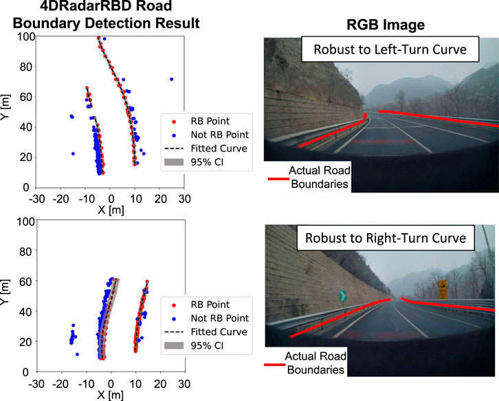
Figure 7. 4DRadarRBD achieves robust detection performance for various road boundary curve shapes.
4.4.4 Sytem temporal stability
Overall, 4DRadarRBD is robust with consistently high accuracy and low Chamfer and Hausdorff distance errors over continuous driving time. As illustrated in Figure 8, during approximately 20 min of continuous monitoring, the method achieves stable low error metrics for most of the duration. Around frame 85, a temporary drop in accuracy and an increase in distance errors occur due to the ground truth system (based on a LiDAR sensor) failing to capture the right-hand road boundary, as confirmed by manual inspection of the corresponding RGB images and point clouds. Notably, even under these circumstances, 4DRadarRBD correctly identifies the road boundaries.
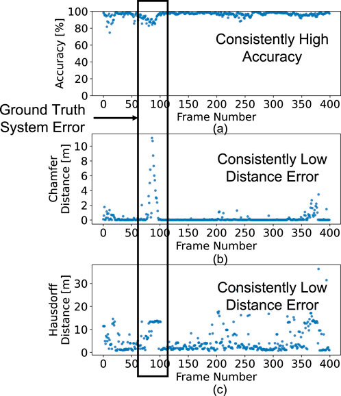
Figure 8. 4DRadarRBD consistently achieves (a) high segmentation accuracy, (b) low Chamfer distance error, and (c) low Hausdorff distance error for road boundary detection over time.
5 Discussion and future work
Our 4DRadarRBD system achieves promising performance in road boundary detection across most evaluated scenarios with a road boundary point segmentation accuracy of 93
Occlusion by vehicles: When the road boundary is occluded by other vehicles, especially large ones such as trucks, the radar signal is reflected back before reaching the road boundary. Consequently, the detected road boundary curve becomes segmented into two parts due to the absence of point cloud data in the occluded region. A potential solution is to develop a predictive model that leverages information from previous frames.
Interference from other radar sources: Another observed failure case occurs when nearby vehicles emit millimeter-wave (mmWave) signals. When such vehicles pass by, the interference generates spurious points in the point cloud with Doppler velocities characteristic of static objects. These artifacts may be misclassified as road boundaries, resulting in false detections.
For future work, we aim to extend our experiments to a broader range of driving environments and corner cases to assess system generalization. Additionally, integrating mmWave radar data with other sensing modalities, such as RGB cameras or LiDAR, represents a promising direction for enhancing robustness and reliability. Furthermore, improvement in radar hardware that provides denser and more precise point clouds with reduced ghost reflections is expected to further improve boundary detection accuracy.
6 Conclusion
In this paper, we introduce 4DRadarRBD, the first 4D mmWave radar-based road boundary detection system that is cost-efficient and robust for complex driving scenarios. We reduce the noisy points by filtering via physical constraints and then segmenting the road boundary points with a distance-based loss. In addition, we capture the temporal dynamics of the point cloud using the vector representing the deviation of the current point from the motion-compensated road boundary detection result from the previous frame. To evaluate 4DRadarRBD, we conducted a real-world driving test in Changping District, China. 4DRadarRBD achieves accurate and robust road boundary detection in various complex driving scenarios with 93
Data availability statement
The original contributions presented in the study are included in the article/Supplementary Material, further inquiries can be directed to the corresponding author.
Author contributions
YW: Conceptualization, Methodology, Validation, Visualization, Writing – original draft. HN: Funding acquisition, Project administration, Writing – review and editing.
Funding
The authors declare that financial support was received for the research and/or publication of this article. This research was funded by Stanford CEE Fellowship and Stanford Blume Center Fellowship.
Conflict of interest
The authors declare that the research was conducted in the absence of any commercial or financial relationships that could be construed as a potential conflict of interest.
Generative AI statement
The authors declare that Generative AI was used in the creation of this manuscript. Generative AI was used to correct grammar of human writing.
Any alternative text (alt text) provided alongside figures in this article has been generated by Frontiers with the support of artificial intelligence and reasonable efforts have been made to ensure accuracy, including review by the authors wherever possible. If you identify any issues, please contact us.
Publisher’s note
All claims expressed in this article are solely those of the authors and do not necessarily represent those of their affiliated organizations, or those of the publisher, the editors and the reviewers. Any product that may be evaluated in this article, or claim that may be made by its manufacturer, is not guaranteed or endorsed by the publisher.
Supplementary material
The Supplementary Material for this article can be found online at: https://www.frontiersin.org/articles/10.3389/frsip.2025.1667789/full#supplementary-material
References
Borgefors, G. (1986). Distance transformations in digital images. Comput. Vis. Graph. image Process. 34, 344–371. doi:10.1016/s0734-189x(86)80047-0
Chen, Z., and Chen, Z. (2017). “Rbnet: a deep neural network for unified road and road boundary detection,” in Neural Information Processing: 24th International Conference, ICONIP 2017, Proceedings, Part I 24, Guangzhou, China, November 14-18, 2017 (Springer), 677–687.
Ester, M., Kriegel, H.-P., Sander, J., and Xu, X. (1996). “A density-based algorithm for discovering clusters in large spatial databases with noise,” in Proceedings of the Second International Conference on Knowledge Discovery and Data Mining. (Portland, Oregon: AAAI Press), 226–231. doi:10.5555/3001460.3001507
Fan, H., Yang, Y., and Kankanhalli, M. (2021). “Point 4d transformer networks for spatio-temporal modeling in point cloud videos,” in Proceedings of the IEEE/CVF conference on computer vision and pattern recognition, Nashville, TN, USA, 20-25 June 2021 (IEEE), 14204–14213.
Guo, K.-Y., Hoare, E. G., Jasteh, D., Sheng, X.-Q., and Gashinova, M. (2014). Road edge recognition using the stripe hough transform from millimeter-wave radar images. IEEE Trans. Intelligent Transp. Syst. 16, 825–833. doi:10.1109/tits.2014.2342875
He, Y., Ma, L., Jiang, Z., Tang, Y., and Xing, G. (2021). “Vi-eye: semantic-based 3d point cloud registration for infrastructure-assisted autonomous driving,” in Proceedings of the 27th annual international conference on Mobile computing and networking, 573–586.
Kang, Y., Roh, C., Suh, S.-B., and Song, B. (2012). A lidar-based decision-making method for road boundary detection using multiple kalman filters. IEEE Trans. Industrial Electron. 59, 4360–4368. doi:10.1109/tie.2012.2185013
Kingery, A., and Song, D. (2024). “Road boundary estimation using sparse automotive radar inputs,” in 2024 IEEE/RSJ International Conference on Intelligent Robots and Systems (IROS), Abu Dhabi, United Arab Emirates, 14-18 October 2024 (IEEE), 13726–13733.
Lang, A. H., Vora, S., Caesar, H., Zhou, L., Yang, J., and Beijbom, O. (2019). “Pointpillars: fast encoders for object detection from point clouds. Proceedings of the IEEE/CVF conference on computer vision and pattern recognition. 12697–12705.
Li, M., Feng, Z., Stolz, M., Kunert, M., Henze, R., and Küçükay, F. (2018). High resolution radar-based occupancy grid mapping and free space detection. VEHITS, 70–81. doi:10.5220/0006667300700081
Liu, X., Yan, M., and Bohg, J. (2019). “Meteornet: deep learning on dynamic 3d point cloud sequences,” in Proceedings of the IEEE/CVF International Conference on Computer Vision, Seoul, Korea (South), 27 October 2019 - 02 November 2019 (IEEE), 9246–9255.
Liu, W., Wang, Y., Shi, J., Shi, Q., and Xu, Z. (2024). Vehicle road lane extraction using millimeter-wave radar imagery for self-driving applications. IEEE Sensors Lett. 8, 1–4. doi:10.1109/lsens.2024.3456120
Mandlik, M., Brazda, V., Paclik, M., Kvicera, M., Carvalho, N., Nouza, T., et al. (2021). “Automotive radar–road boundary estimation,” in 2021 International Symposium ELMAR (IEEE), Zadar, Croatia, 13-15 September 2021 (IEEE), 123–126.
Medina, F. P., and Paffenroth, R. (2021). Machine learning in lidar 3d point clouds. Adv. Data Sci., 113–133. doi:10.1007/978-3-030-79891-8_6
Park, J., Kim, C., Kim, S., and Jo, K. (2023). Pcscnet: fast 3d semantic segmentation of lidar point cloud for autonomous car using point convolution and sparse convolution network. Expert Syst. Appl. 212, 118815. doi:10.1016/j.eswa.2022.118815
Patel, D., and Elgazzar, K. (2022). “Road boundary detection using camera and mmwave radar,” in 2022 5th International Conference on Communications, Signal Processing, and their Applications (ICCSPA), Cairo, Egypt, 27-29 December 2022 (IEEE), 1–7.
Patel, D., and Elgazzar, K. (2024). Deep learning based road boundary detection using camera and automotive radar. IEEE Intell. Veh. Symp., 3235–3240. doi:10.1109/iv55156.2024.10588554
Popov, A., Gebhardt, P., Chen, K., Oldja, R., Lee, H., Murray, S., et al. (2022). Nvradarnet: real-time radar obstacle and free space detection for autonomous driving. arXiv preprint arXiv:2209.
Qi, C. R., Yi, L., Su, H., and Guibas, L. J. (2017). Pointnet++: deep hierarchical feature learning on point sets in a metric space. Adv. neural Inf. Process. Syst. 30. doi:10.5555/3295222.3295263
Rockafellar, R. T., and Wets, R. J.-B. (2009). Variational analysis, 317. Springer Science and Business Media.
Southcott, M. A., Zhang, L., and Liu, C. (2023). Millimeter wave radar-based road segmentation. Radar Sens. Technol. XXVII (SPIE) 12535, 200–205. doi:10.1117/12.2661942
Suleymanoglu, B., Soycan, M., and Toth, C. (2024). 3d road boundary extraction based on machine learning strategy using lidar and image-derived mms point clouds. Sensors 24, 503. doi:10.3390/s24020503
Sun, P., Zhao, X., Xu, Z., Wang, R., and Min, H. (2019). A 3d lidar data-based dedicated road boundary detection algorithm for autonomous vehicles. IEEE Access 7, 29623–29638. doi:10.1109/access.2019.2902170
Sun, L., Li, Y., and Qin, W. (2024). Pepillar: a point-enhanced pillar network for efficient 3d object detection in autonomous driving. Vis. Comput. 41, 1777–1788. doi:10.1007/s00371-024-03481-5
Taher, H. B., Hashem, K. M., and Sajet, F. A. (2018). Proposed method for road detection and following boundaries. J. Theor. Appl. Inf. Technol. 96.
Wang, G., Wu, J., He, R., and Tian, B. (2020). Speed and accuracy tradeoff for lidar data based road boundary detection. IEEE/CAA J. Automatica Sinica 8, 1210–1220. doi:10.1109/jas.2020.1003414
Wei, Y., Liu, H., Xie, T., Ke, Q., and Guo, Y. (2022). “Spatial-temporal transformer for 3d point cloud sequences,” in Proceedings of the IEEE/CVF winter conference on applications of computer vision, 1171–1180.
Wen, Q., Yang, Z., Song, Y., and Jia, P. (2008). “Road boundary detection in complex urban environment based on low-resolution vision,” in 11th Joint International Conference on Information Sciences. (Shenzhen, China: Atlantis Press), 208–214.
Williams, C., and Rasmussen, C. (1995). Gaussian processes for regression. Adv. neural Inf. Process. Syst. 8. doi:10.5555/2998828.2998901
Wu, J., Jiao, J., Yang, Q., Zha, Z.-J., and Chen, X. (2019). “Ground-aware point cloud semantic segmentation for autonomous driving,” in Proceedings of the 27th ACM international conference on multimedia, 971–979.
Xu, F., Wang, H., Hu, B., and Ren, M. (2020). Road boundaries detection based on modified occupancy grid map using millimeter-wave radar. Mob. Netw. Appl. 25, 1496–1503. doi:10.1007/s11036-019-01378-5
Xu, P., Liu, S., Zhang, Y., Wu, X., and Zhao, D. (2025). Urban road boundary detection method based on 3d lidar and road shape classification. Measurement 256, 118073. doi:10.1016/j.measurement.2025.118073
Zhang, Y., Wang, J., Wang, X., Li, C., and Wang, L. (2015). “3d lidar-based intersection recognition and road boundary detection method for unmanned ground vehicle,” in 2015 IEEE 18th International Conference on Intelligent Transportation Systems (IEEE), Gran Canaria, Spain, 15-18 September 2015 (IEEE), 499–504.
Zhang, Y., Zhu, Y., Liu, Z., Miao, C., Hajiaghajani, F., Su, L., et al. (2022). “Towards backdoor attacks against lidar object detection in autonomous driving,” in Proceedings of the 20th ACM conference on embedded networked sensor systems, 533–547.
Keywords: 4D mmwave radar, road boundary curve detection, point cloud, road boundary point segmentation, milimeter wave radar
Citation: Wu Y and Noh HY (2025) 4DRadarRBD: 4D mmWave radar-based road boundary detection in autonomous driving. Front. Signal Process. 5:1667789. doi: 10.3389/frsip.2025.1667789
Received: 17 July 2025; Accepted: 30 October 2025;
Published: 20 November 2025.
Edited by:
Jonatan Ostrometzky, Tel Aviv University, IsraelReviewed by:
Mohammed Jahangir, University of Birmingham, United KingdomAkanksha Sneh, Indraprastha Institute of Information Technology Delhi, India
Copyright © 2025 Wu and Noh. This is an open-access article distributed under the terms of the Creative Commons Attribution License (CC BY). The use, distribution or reproduction in other forums is permitted, provided the original author(s) and the copyright owner(s) are credited and that the original publication in this journal is cited, in accordance with accepted academic practice. No use, distribution or reproduction is permitted which does not comply with these terms.
*Correspondence: Yuyan Wu, d3V5dXlhbkBzdGFuZm9yZC5lZHU=