 Aníbal Moncada1,2*†
 Ivan P. Damians1,2,3†
- 1Department of Civil and Environmental Engineering (DECA), Universitat Politècnica de Catalunya·BarcelonaTech (UPC), Barcelona, Spain
- 2Geomechanics group, International Centre for Numerical Methods in Engineering (CIMNE), Barcelona, Spain
- 3VSL International Ltd., Barcelona, Spain
The present document presents a review on the use of the finite element software package CODE_BRIGHT to simulate reinforced soil structures (RSS). RSS are composed of longitudinal steel or polymeric materials, placed orthogonal to the main stress direction in a soil mass, acting as tension-bearing elements. A common application of RSS is in retaining structures, in the form of reinforced soil walls (RSWs). RSW are usually designed with analytical methods, which have limited capabilities when predicting a structure’s deformation response. To improve on this, the use of numerical tools allows to quantify the stress-strain response of complex, compound structures, such as RSWs. Several factors must be considered when modelling RSS, including reinforcement response, which can be non-linear under several circumstance (including time- and temperature-dependencies), soil-reinforcement interaction, soil-structure interaction, and soil response, all of which can be affected by the presence of moisture. Using laboratory measured data, the individual response of reinforcements (e.g., creep elongation), as well as the compound behaviour of soil-reinforcement material (e.g., pullout response) can be simulated to explore individual and compound response. Depending on the modelled phenomena, numerical simulations may include 2D and 3D representations. For full-scale reinforced soil walls, the stress-strain response within the soil mass, reinforcements, concrete facing panels, and connections can be studied in magnitude and distribution. Details regarding special considerations of how to model such structures with CODE_BRIGHT and other commercially available software are provided. Insights on the thermo-hydraulic repone of RSWs are covered. Advantages, limitations and future lines of research in the use of CODE_BRIGHT are explored.
1 Introduction
CODE_BRIGHT (Olivella et al., 1996; CODE_BRIGHT, 2024) is a finite element software package intended to analyse the thermo-hydro-chemo-mechanical (THCM) response of geological media. CODE_BRIGT (from here on, referred as CB) is most often used in the analysis of expansive soils (e.g., Alonso and Olivella, 2008; Ramon et al., 2017), nuclear waste depositories (e.g., Damians et al., 2019; Toprak et al., 2024) and gas migration problems (e.g., Damians et al., 2020; Tamayo-Mas et al., 2024). Nevertheless, as with many finite element packages, CB can be used in many different structural applications.
The soil-structure interaction of compound structures has proved to be one of cornerstones in many numerical simulations. With this in mind, reinforced soil structures (RSSs), which usually combine several different structural materials, stand out as complex numerical problems. RSS are commonly used in the civil, geotechnical, and mining industry as earth retaining structures, slope reinforcement, and basal reinforcement. Said structures are composed of a compacted material (usually cohesionless, high quality granular soil) with intercalated reinforcement layers perpendicular to the main stress direction (most often than not, horizontal, see Figure 1A). Reinforcement elements can be discrete (e.g., straps) or continuous (e.g., grids or mats), and be made of steel or polymeric (also referred as geosynthetic) materials. One of the most frequent applications of reinforced soil are reinforced soil walls (RSWs). This structured are often used in highway and railway embankments, and general retaining wall solutions (see Figure 1B).
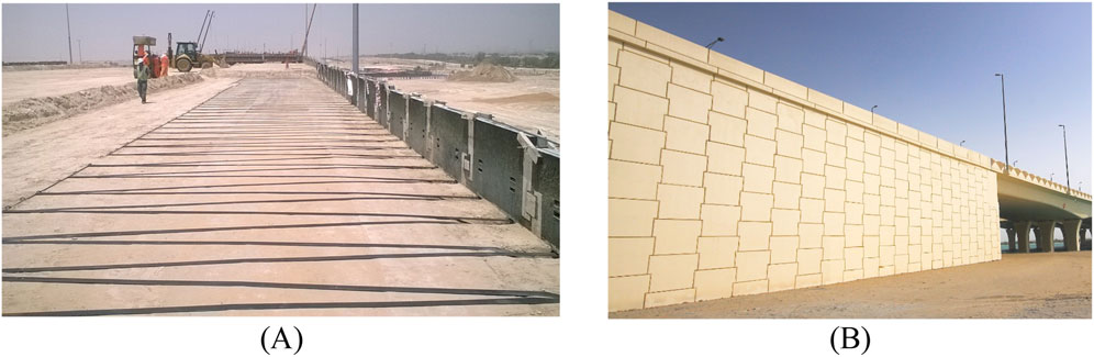
Figure 1. (A) Horizontal geostrap reinforcement layout and (B) finished view of a reinforced soil wall (courtesy of VSL International).
Numerical tools have a proven record in modelling RSWs. As retaining structures, RSW are expected to present relatively small displacements, which fits quite well into numerical techniques such as the finite element method (Augarde et al., 2021). Different software packages, using either finite difference and finite element methods, can be found in the literature, for both metallic and polymeric reinforcements (e.g., Bathurst and Hatami, 2001; Hatami and Bathurst, 2005; Huang et al., 2009; Yu et al., 2015; Cristelo et al., 2016; among others). The advantage of using numerical tools to analyse RSS relies on properly quantifying the stress-strain distributions along the reinforcement elements, as the main internal failure mechanisms are directly related to the maximum reinforcement tension (i.e., reinforcement rupture failure), the soil-reinforcement interaction (i.e., pullout failure), and the tension at the connections (i.e., connection rupture failure) (AASHTO, 2024; BS8006-1, 2016). In the latest revision of the European design standard for design of geotechnical structures (EN-1997, 2025), numerical models are now allowed as primary design tools, rather than just verification or secondary design methods. Malekmohammadi and Damians (2024) provided a thorough literature review of reinforced soil walls related topics, in which numerical analyses were found to be a consistently relevant topic in past and recent years. Complex solutions such as back-to-back walls, tiered walls, and bridge abutments stand out as more recent research topics, which goes hand-in-hand with the use of numerical tools, as many complex structures usually fall outside the scope of standard analytical methods. Thus, a literature review to describe the uses of CB in the numerical modelling of RSS seems rather natural, as to provide further tools for practitioners, designers, and researchers.
Numerical tools such as FLAC have a proven record in modelling reinforced soil structures (see Bathurst, 2014). While having an ample backlog of soils and rocks constitutive models, CB has been scarcely used to simulate structural applications such as reinforced soil structures The aim of this study is to review past examples of reinforced soil applications using the finite element tool CODE_BRIGHT, with focus on the specific materials and components (i.e., discrete facing elements, discrete and/or continuous reinforcement layer, retained and reinforced soil, and connection elements) as well as the compound response of full-scale reinforced soil structures in order to motivate its future use for structural applications. Literature examples are used to evidence the capabilities of CB in tackling the complex, compound, response of reinforced soil structure using different assumptions and techniques. The main focus of the review are RSWs.
2 Methodology
The present work used the Scopus database as a primary source of data. The search method included the original publication of CB (i.e., Olivella et al., 1996) as a first filter, from which 585 in-English publications were found. As the focus of this document are reinforced soil structures, search results were narrowed done using specific keywords, including: reinforcement; reinforced soil; mechanically stabilized earth (MSE); geosynthetics; polymeric materials, pullout failure; and soil-reinforcement interaction. Using specific keywords lead to a total of seven documents related to the numerical modelling of reinforced soil structures using CB. Table 1 shows the main aspects of the publications relevant to the use of CB included in this review. Due to the low number of search outcomes, conferences and journal publications were included. Publications regarding reinforced soil structures account for under 2% of the total publications which refer to the use of CB. All publications belong to the same research group at Universitat Politècnica de Catalunya·BarcelonaTech (UPC) and International Centre for Numerical Methods in Engineering (CIMNE), meaning that the use of CB in reinforced soil applications is still niche. Mentioned articles were published within the last 5 years, which implies that CB has only recently begun to be used in the simulation of reinforced soil structures. This can also be said after analysing the papers content, as only basic, idealized structures are modelled, leaving out more complex configurations such as tiered walls and bridge abutments. The numerical approach used in the published articles (i.e., CB software) is qualitatively compared with relevant and current research related to the field of reinforced soil structures, gathered, mainly, from the literature reviews carried out by Malekmohammadi and Damians (2024) and Paiva et al. (2024).
Table 1. Search results for articles related to numerical modelling of reinforced soil structures using CODE_BRIGHT.
3 Soil-structure interactions
In compound geotechnical structures, the soil-structure interaction plays a vital role in the proper simulation of the systems response. For RSWs, the system’s response will vary depending on the soil-facing and soil-reinforcement interaction. Most numerical tools rely on three methods to simulate the interaction between materials, those are zero-thickness (or virtual thickness) (e.g., PLAXIS, 2024), spring elements (e.g., FLAC, Itasca, 2024), and continuum elements (applicable in most numerical tools) (see Figure 2). For zero-thickness elements, a reduction factor (Ri) is applied to strength and stiffness properties of the adjacent soil, assigned to a (usually non-modifiable) virtual thickness, in which the corresponding nodes of the two adjacent materials share the same coordinates. Spring elements are commonly defined by a normal and shear stiffness. For continuum elements, equivalent strength and stiffness properties can be separately assigned to a real thickness (Damians et al., 2022). Assigning properties over a specific domain, rather than a virtual thickness, has the advantage of using user defined element sizes and shapes, as well as different constitutive material properties based on the value of Ri.
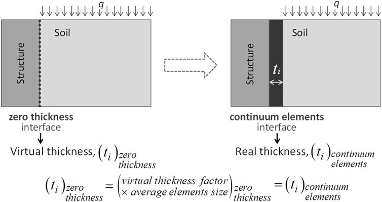
Figure 2. Zero-thickness and continuum elements modelling approach (adapted from Damians et al., 2015).
Damians et al. (2022) performed extensive modelling work to validate the use of continuum elements for soil interfaces. Using a reduced model of a soil block with a concrete facing, simulations were undergone to show the effect of mesh sizes, elements type, strength and stiffness reduction factor, and interface thickness. Analyses were carried out in 2D and 3D representation, used to further validate plane-strain assumptions. Continuum elements were simulated using PLAXIS, FLAC, and CODE_BRIGHT. Results showed a proper agreement of simulated results, in 2D, for normal and shear stresses across three numerical tools (see Figure 3). The influence of mesh size and element type over total shear strains was studied using 3D representations, in which minor differences were observed between scenarios (see Figure 4). Increasing the value of Ri (i.e., stiffer interfaces) resulted in reduced shear strains and relative displacements. Variations of interface thickness was judged to have negligible influence as long as material properties were adjusted accordingly Reasonable agreement was observed between 2D and 3D interface response when using continuum elements, in which the effects of mesh size and element type showed to be equally relevant, if not more, than the model dimensions (i.e., 2D or 3D).
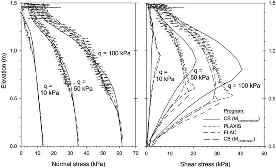
Figure 3. Load transfer from backfill soil to facing panel using 2D continuum element interfaces with a reduction factor Ri = 0.8 using CODE_BRIGHT (CB), PLAXIS, and FLAC (adapted from Damians et al., 2022).
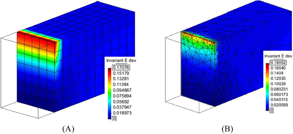
Figure 4. Total shear strains for a surcharge of 100 kPa, interface thickness of 18 mm, and reduction factor of Ri = 0.8 using (A) hexahedron structured medium mesh and (B) tetrahedron unstructured irregular mesh (adapted from Damians et al., 2022).
Overall, when simulating mechanical problems, the use of continuum or zero-thickness elements does not appear to provide a substantial advantage of one over the other. Zero-thickness elements results in limited capabilities for the user to define material properties. The use of continuum elements to simulate interfaces requires from users to adapt the geometry of the problem to include the equivalent thicknesses. Thus, an increased number of nodes (and elements) can result in increased calculations times.
In coupled problems (e.g., hydro-mechanic), interface zones can accumulate large displacements or shear deformations, which can lead to a large concentration of, for example, pore pressures. As zero-thickness elements are made up of a single node, convergency issues could arise due to the pressure differences with the neighbouring soil element. On the other hand, continuum elements, having an equivalent thickness and a larger node count (e.g., five element thick interfaces would have four nodes) allow for a gradient across the nodes within the equivalent thickness, as well as more control over hydraulic and/or thermal properties of the interface, possibly removing said numerical issues.
One of the main internal failure modes of RSWs is the pullout of reinforcement due to failure of the soil-reinforcement interface (AASTHO, 2024). The shear response of the soil-reinforcement interface is commonly studied using pullout tests. Said tests can be undergone in-situ, using pre-installed samples which will not affect the structures integrity, or using specialized laboratory equipment (see Figure 5A), which allow the replication of in-situ soil conditions. Likewise, numerical simulations of pullout tests can allow for representative results (Palmeira, 2009) given that the domain is properly modelled (see Figure 5B), including all equipment details (e.g., front-opening with metal sleeve (see Figure 5C), and a suitable soil-reinforcement interface using, for example, continuum elements (see Figure 5D). As shown by Damians et al. (2024), special care must be put into the number of elements that conform the equivalent interface thickness when using continuum elements (see Figure 6A).
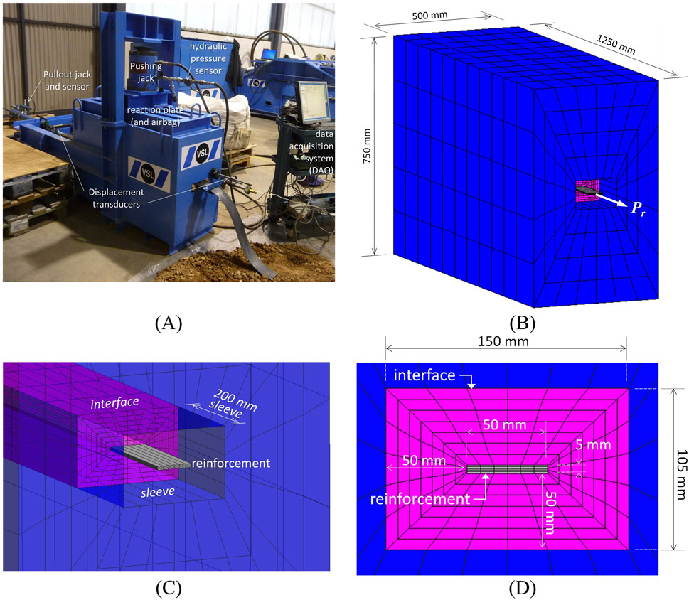
Figure 5. (A) Physical pullout box equipment, (B) pullout box domain geometry, (C) front opening and sleeve, and (D) soil-reinforcement interface mesh details (adapted from Damians et al., 2024).
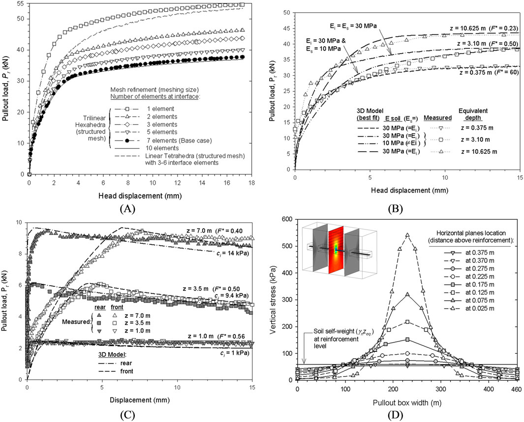
Figure 6. (A) Reinforcement pullout load versus axial displacement with regards to interface mesh refinement, calibrated displacement and pullout load from measured and modelled pullout tests results with (B) steel ladders and (C) polymeric straps, and (D) vertical stress development at the interface in a cross-section plane at the end of the pullout test (adapted from Damians et al., 2024).
Depending on the reinforcement material (i.e., metallic or polymeric), the pullout response can be expected to be significantly different. Extensible (i.e., polymeric) materials present a gradual stretching along the reinforcement’s length as stress increases, while inextensible (i.e., metallic) reinforcements have an instantaneous stress-strain response along the whole reinforcement’s length (Abdelouhab et al., 2010; Miyata et al., 2018). With this in mind, the capability of finite element tools in simulating the pullout response of different reinforcement materials has already been evidenced in past research (e.g., Hussein and Meguid, 2020). An example of this is the work of Damians et al. (2024). They used 3D representations in CB to simulate the stress-strain response of pullout failures of different reinforcement materials. After a thorough calibration (as with any numerical simulation) the inextensible response of steel ladder (see Figure 6B) and the extensible response of polymeric straps (both at front- and tail-end) (see Figure 6C) was found to be in proper agreement with physical results for different simulated depths (z). More details on the modelling of polymeric reinforcement elements can be found in the follow sections.
An added advantage of using 3D models to simulating pullout response is the visualization of the transversal stress profile (and consequent vertical displacements) along the reinforcement’s length (see Figure 6D). As described by Alfaro and Pathak (2005), and shown by numerical results, the effect of dilatancy is significant in pullout failure. The use of calibrated numerical tools allows for a thorough understanding of the soil-reinforcement response without the need of numerous (and costly) physical tests. Further details regarding the soil-reinforcement and soil-facing interface modelling using CB can be found in Damians et al. (2021), Damians et al. (2022), and Damians et al. (2024).
Several examples of pullout response simulations using different numerical tools can be found in the literature (e.g., Amirhosseini et al., 2022). In the case of a purely mechanical response, CODE_BRIGHT results as a viable alternative, with no particular advantages or disadvantages compared to other numerical tools. In the case of ribbed elements, such as extruded geogrid reinforcements, the use of discrete element models (DEM) could provide further information on the mechanical response due to the discrete nature of the reinforcement itself (e.g., Verma et al., 2025). Finally, understanding of thermal influences over pullout response is a novel research topic (e.g., Lin et al., 2024; Han et al., 2025), which could take advantage of the coupled formulation of CODE_BRIGHT.
4 Reinforcements
Reinforcement elements can be broadly categorized in extensible and inextensible materials. Steel elements fall in the inextensible materials, while polypropylene and polyethylene materials, usually in the form of grids and mats, fall in the extensible category. Polyester (PET) materials (e.g., PET geostraps), while usually having higher stiffness values compared to polyolefins, still fall within the extensible category (Miyata et al., 2018).
Inextensible reinforcements can be easily modelled using linear elastic models, in which a single elastic modulus adequately represents the response of, say, steel ladders, with plenty of examples available in the literature (e.g., Abdelouhab et al., 2011; Damians et al., 2013; Yu et al., 2015; among others).
In the case of extensible reinforcements, the correct numerical representation is not trivial. Polymeric materials are proven to be rate-dependent, that is, their short- and long-term response will depend on load, time, and in-soil temperature (Koerner et al., 1988; Hsuan et al., 2008; Greenwood et al., 2012). Short-term response can be highly non-linear as strains increased, while the long-term will depend on complex phenomena such as creep and stress-relaxation. Kaliakin and Bathurst (2005) recognized that most (if not all) constitutive models for polymeric materials are phenomenological in nature and require extensive curve-fitting procedures. A straightforward and commonly used method to account for the changes of strength and stiffness in time is the use of isochronous stiffness curves. By means of laboratory creep test data, the stiffness for, say, 1,000 h (i.e., common time of completion for RSWs construction) and 2% strain (i.e., maximum expected strain under service conditions), can be calculated and in analytical and numerical models (Bathurst and Naftchali, 2021). Chenari and Bathurst (2023) used finite difference method together with a two-component hyperbolic stiffness model to evaluate the effects of reinforced foundation layers placed atop a soft clay layer. Their results showed how increased reinforcement stiffness can increase ultimate bearing capacity. Nevertheless, the long-term response will depend heavily on the stiffness reduction in time. By using PCF/FLAC, Tizpa et al. (2023), reached similar conclusion when analyzing the problem of a granular fill over a void, where increased reinforcement stiffness yields increased bearing capacity.
If the scope of the simulation is the continuous response over time rather than at a specific moment (e.g., end of construction), sophisticated constitutive models are required. One alternative is the use of viscoplastic constitutive models, in which a fluidity (or hardening) parameter can be defined as load-, strain-, time-, and/or temperature-dependent. Moncada et al. (2024a) proposed and implemented a constitutive model based on Perzyna (1966) viscopalstic formulation, allowing the simulation of primary and secondary stage creep response. Similar viscoplastic constitutive models have been used to model geosynthetics response (e.g., Eldesouky and Brachman, 2020; Deng and Huangfu, 2021; Zhao et al., 2024). A downside of this approach is the extensive calibration process required prior to the modelling of each material. Moncada et al. (2024a) simulated the rate-dependent response using a double viscosity function based on accumulated plastic strains. For this, creep measured results from PET strap reinforcements (see Figure 7A) were used. Model parameters were calibrated for load- (i.e., individual creep curve results) (Figure 7B) and product-specific scenarios (i.e., overall response for a, say, grade 50, PET geostrap reinforcement) (Figure 7C) using laboratory measured creep curves from an ample dataset. If only one mechanism required (e.g., primary creep), one of the two viscous components can be deactivated (see Figure 7D). This can be useful when modelling GRSW’s service conditions, as secondary creep can be expected to occur only if load conditions surpass loads of 50% of the material ultimate tensile strength, approximately, while service loads can be expected to fall under 10% of said value (Miyata et al., 2018). Idealized scenarios showed the capabilities of the model to modify the creep response with varying temperature (see Figure 8A) and relative humidity (se Figure 8B) boundary conditions. Additionally, the implemented model was shown to be capable of simulating stress-relaxation response while under constant rate of strain conditions (see Figure 8C). There is scarce evidence in the literature of rate-dependent models used in full-scale RSWs simulations, and even less so of coupled scenarios. The implementation of such models within CB can pave the way for future pioneering case studies.
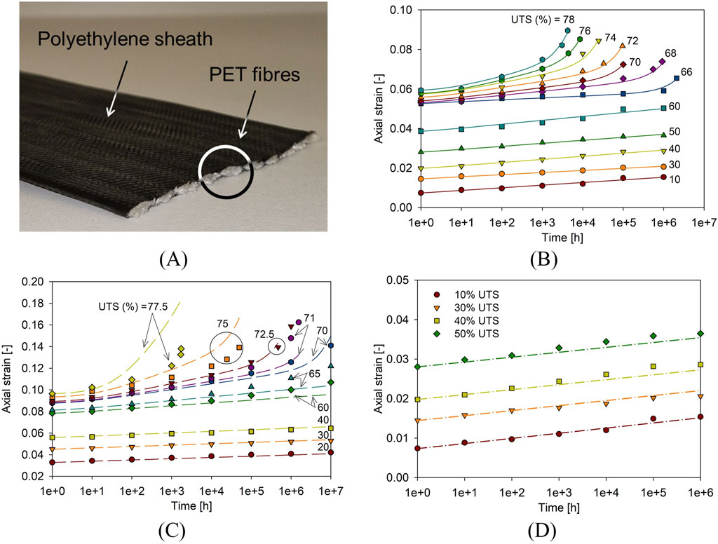
Figure 7. (A) PET strap reinforcement sample and comparison of measured (symbols) and model results (lines) with CODE_BRIGHT for (B) load-specific calibration, (C) product-specific calibration, and (D) primary creep only model for various grade 50 polymeric strap (i.e., ultimate tensile strength of 50 kN/strap) (adapted from Moncada et al., 2024a).
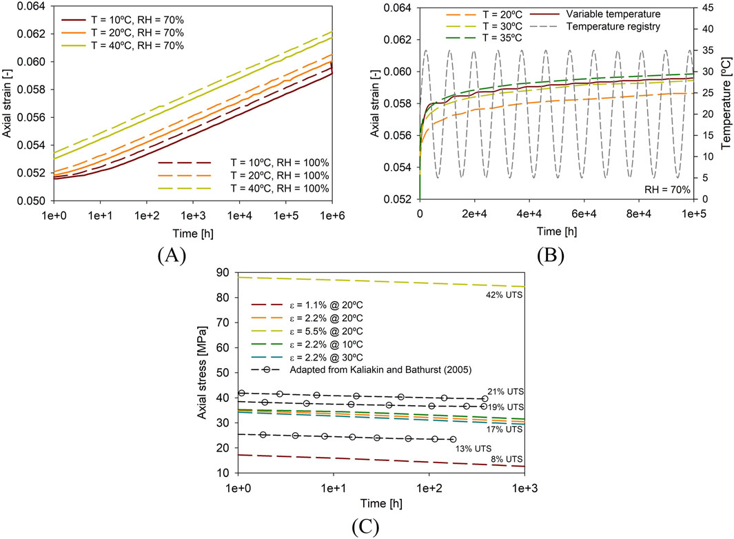
Figure 8. Finite element model results using CODE_BRIGHT for (A) different fixed temperatures and relative humidity values, (B) varying boundary conditions, and (C) stress-relaxation (adapted from Moncada et al., 2024a).
5 Facing panel and connections
The facing and connection elements are a fundamental aspect of reinforced soil structures, particularly for retaining wall solutions. Depending on the facing and reinforcement typology, connections elements can vary from bodkin-type connections, to steel rods and pins, or void-formed segments, among other solutions. In the case of precast concrete panels and polymeric strap reinforcements, a common solution is prefabricated void sections, by which the polymeric strap can be passed through (see Figure 9A).
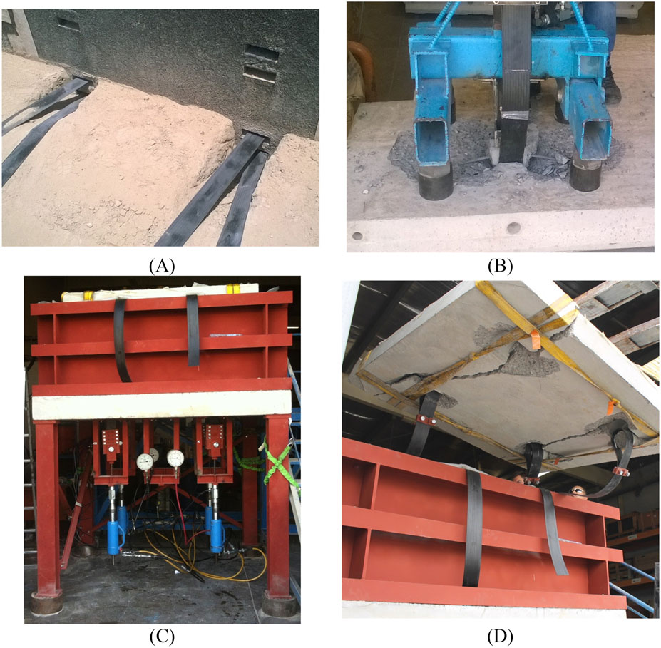
Figure 9. (A) Detail of void-formed connections, and concrete panels physical tests of (B) single connection pullout, (C) whole panel pullout, and (D) post-failure conditions. (adapted from Damians, 2022).
Regardless of the type, connections must be design and tested accordingly. Laboratory tests should be design in such a way that on-site conditions are properly simulated. Single connection pullout tests can be carried out to evaluate the isolated response (see Figure 9B), while whole panel pullout tests can allow to properly assess the response of the complete system (Figure 9C), including the influence of surrounding soil and the compound response (and failure) of several connections (see Figure 9D).
Due to the geometric characteristic of the facing-reinforcement system, physical tests can be hard to come by. As shown by Damians (2022), numerical tools are a useful alternative to physical tests. By using CB, the global (see Figure 10A) and local (see Figure 10B) failure response can be analysed, which provides useful insight on the systems loads and deformations without the need of an extensive campaign of expensive and technically challenging physical tests. As concrete and steel materials are usually modelled with linear elastic models in geotechnical structures, at first glance, using CB does not provide any advantages.
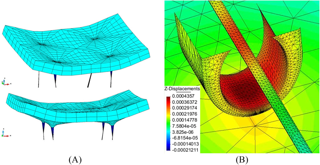
Figure 10. Modelling of (A) global panel response and (B) individual void-form connection displacement response using CODE_BRIGHT (adapted from Damians, 2022).
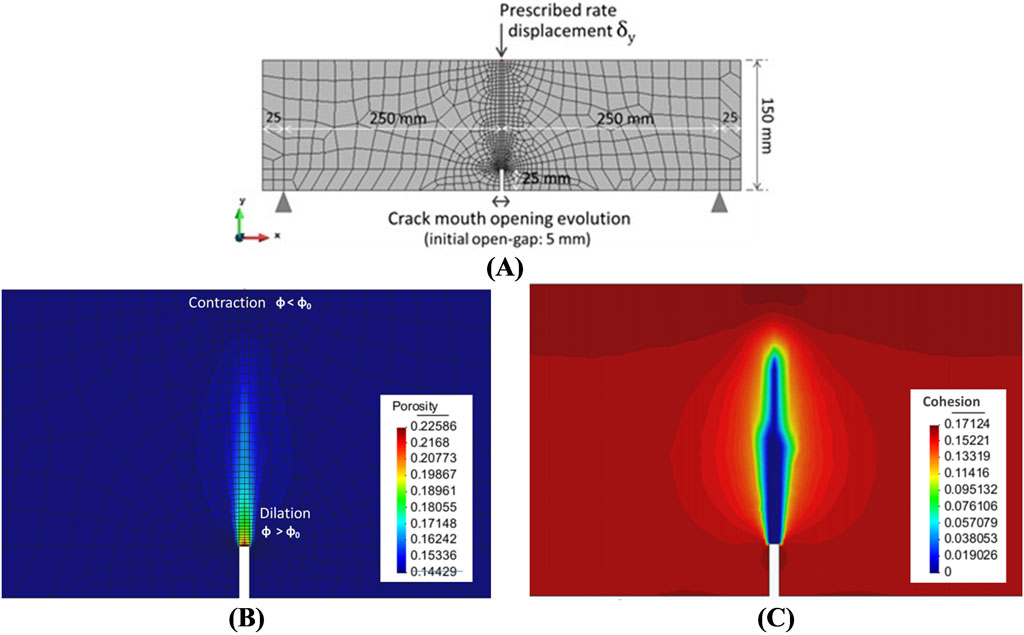
Figure 11. Numerical simulation of a flexural test of a fibre-reinforced concrete sample with a porosity dependent constitutive model to simulate reinforcing fibres: (A) mesh domain, (B) porosity variations, and (C) loss of cohesion after test simulation (adapted from Damians et al., 2018).
A viable alternative to reduce reinforcing steel in facing panels is the use of fibre-reinforced concrete. This type of material not only has increased strength, but also can reduce the shrinkage phenomena curing the strengthening process. For this, fibres are included in the wet concrete mix and can help reduce material and installation costs. Figure 11A shows a concrete sample subjected to a flexural test (as per EN 14651, 2008). In this case, the constitutive model used for the concrete includes a resisting parameter (i.e., additional cohesion) as a function of porosity which provides added strength, simulating the embedded fibres. As porosity increases due to cracking of the sample (see Figure 11B), the additional strength is reduced, until a critical porosity value in which the fibres do not provide any additional strength (see Figure 11C). Fibre reinforced concrete could be used for different facing elements of reinforced soil structures, such as precast concrete panels, or, in shotcrete layers commonly used in geotextile-covered facings. Outside of reinforced soil structures, the use of fibre-reinforced concrete could be used to model tunnel applications. An example is the work of Damians et al. (2018), in which a porosity-dependent constitutive model was used to model a tunnel section with a 6.26 m radius within a rock mass (see Figure 12A). The tunnel sections include an invert, shotcrete lining (see Figure 12B), and steel trusses (see Figure 12C), all of which are constructed in sequence after equilibrium and excavation stages. Numerical simulations allow to compare the stress-strain response of the underground structure and compare between non-reinforced and fibre-reinforced solutions. Likewise, displacement fields can be analysed (see Figure 12D).
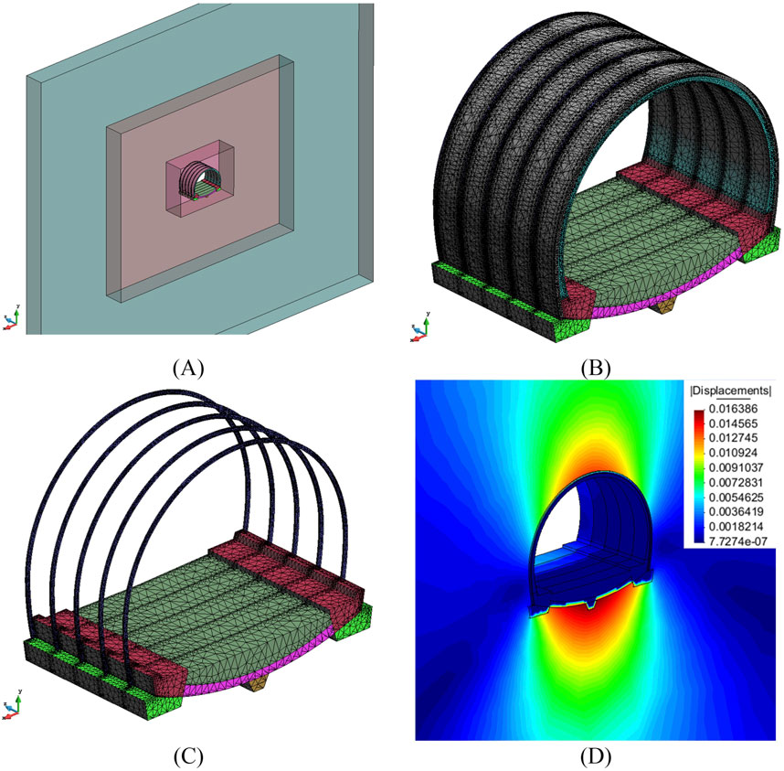
Figure 12. CODE_BRIGHT simulation of a (A) Tunnel section domain, (B), tunnel section detail with shotcrete cover, (C), steel arches detail, and (D) simulated displacements (m) after construction (adapted from Damians et al., 2018).
6 Full scale reinforced soil walls
To simulate a full-scale RSW all the previously describe elements (interfaces, reinforcements, connections) must be accounted for. Damians et al. (2021) used CB to simulate a 3D, 6-m-hight, and 1-m-wide strip-reinforced soil wall (see Figure 13A) to study the influence of reinforcement type. Among their main conclusions, no practical advantage of 3D models over 2D representations for planar reinforcement arrangements (e.g., sheets and grids) and no surcharge conditions. On the contrary, for discrete reinforcement layers (e.g., ladders and straps), 2D plain-strain conditions do not allow to correctly simulate the stress-strain distributions in the vicinity of the reinforcement, while 3D models allow for a more realistic outcomes (see Figure 13B), albeit, at a considerably higher computational cost. Finally, for global stability analyses, or if calibrated 2D models are available, the use of 3D models does not provide further benefits. Akbar et al. (2024) developed a 3D RSW model using the finite element tool ABAQUS (2016) and reached similar conclusions. Another modelling approach can be the use of finite element limit analysis (FELA) Fathipour et al. (2021) used FELA to model geosynthetic reinforced soil walls and clouded, in a similar manner to Damians et al. (2021), the location of the maximum tensile load of reinforcement layers being in proximity to the facing elements, mostly due to the relative displacements of the stiff facing and the compressible soil. When comparing past modelling attempts of full-scale structures, CB appears to be a viable tool, with no particular benefits for purely mechanical simulations.
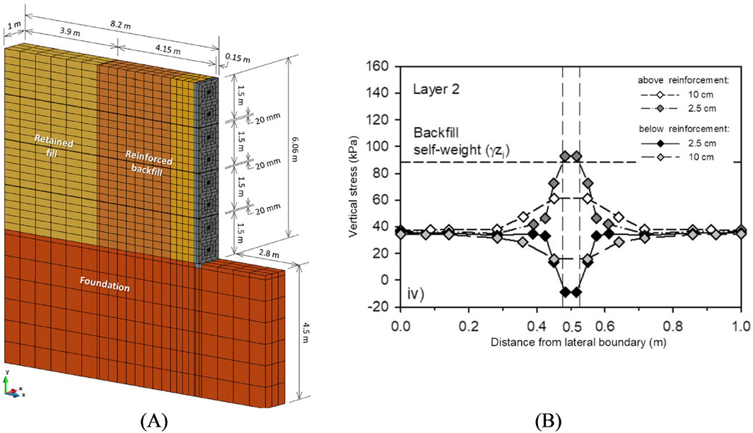
Figure 13. (A) 3D model overview of a full-scale reinforced soil wall, and (B) vertical pressure distribution at and in the vicinity of the reinforcement strip at 0.25 m back from the facing element for a steel reinforcement (adapted from Damians et al., 2021).
Another topic of interest in RSW with discrete facing elements is the use of different bearing elements in between panels. The purpose of bearing pads is to avoid cracking caused by the direct contact between panels. Depending on the stiffness of the pads (given by the used material and the number of placed pads), the displacements of the facing will vary and, to some extent, the system’s loads. Commercial software (e.g., PLAXIS; FLAC) are frequently used to simulate the response of full-scale walls (e.g., Mirmoradi et al., 2021). In this regard, CB does not offer a particular numerical advantage compared to other numerical software when modelling mechanical response by itself (i.e., non-coupled problems). As with most numerical tools, when properly selecting material properties CB has been shown to be able to properly reproduce the compound response of complex geotechnical structures such as full-scale reinforced soil walls Damians et al. (2021).
Modelling more complex reinforced soil structures, such as back-to-back walls and bridge abutments, requires robust numerical tools. In a thorough literature review of geosynthetic reinforced soil integrated bridge abutments, Abdullah et al. (2023) highlights that most of the recent research focus on numerical modelling uses PLAXIS or FLAC software. An example of this is the work of Shen et al. (2020), in which FLAC was used to study working stress conditions of a geosynthetic reinforced bridge abutment subjected to bridge slab loading.
A noticeable difference with other numerical tools is in the form of structural elements. CB relies on assigning material properties over a user-defined geometry (and mesh), which, while allowing more control over the system properties and response, increases the required expertise to carry out simulations. Using continuum elements to define materials can be done in most commercial software but is not a common technique. Most commercial software (e.g., PLAXIS, FLAC, among others) have plate, beam, joint, hinge, or other type of elements which simulate structural components such as reinforcement layers and connection materials. These materials have properties specific, such as only carrying axial loads, which make the modelling process more straightforward and reduces the required input from the user when assigning material properties. An example of this is the previously described zero-thickness and continuum interfaces.
Plenty of design tools are usually based on limit equilibrium analysis, in which safety margins can be easily calculated (e.g., RSWall, Rocscience Inc, 2025). In the case of numerical methods, software can have in-built design tools to optimize or calculate margins of safety. An example of this is the software PLAXIS, which, by using the c-phi reduction method, can calculate the global factor of safety for a given set of conditions. Moncada et al. (2023) used CB to manually simulate the strength reduction process following the latest European design guidelines (EN 1997-3, 2025) for an idealized geosynthetic RSW. Their results show how a possible shear failure was generated across the reinforced fill structure as soil properties were reduced. Having said that, unlike other numerical tools, CB lacks automatic optimization tools.
Reinforced soil walls are flexible structures which have proven their performance in seismic conditions. Research has shown that reinforcement stiffness is one of the key factors affecting the seismic performance of reinforced soil walls (Sabermahani et al., 2009; Panah et al., 2015). An example of dynamic response of reinforced soil structures using finite element models is the work of Ren et al. (2024). They observed that reinforcement layout and distribution directly relates to the dynamic performance. A clear limitation of CODE_BRIGHT is the lack of seismic-related options. Even though CB’s constitutive model library has cyclic strength of stiffness degradation models, current boundary conditions do not allow for dynamic analyses.
Due to economic, environmental, or functional requirements, different types of soils and materials could be considered as backfill. Recycle concrete aggregates and marginal soils (i.e., granular soils with high fines content, often excavation within the construction site) stand out as two popular alternatives for reinforced soil structures (e.g., Vieira and Pereira, 2015; Samtani and Nowatzki, 2021; Palmeira et al., 2021). These types of materials are usually considered a more sustainable solution compared to quarried granular material, hence, the ability to model their response must not be disregarded. Whichever the alternative material might be, hydraulic and thermal parameters can vary (e.g., a higher fines content results in a lower intrinsic permeability, while the composition and size distribution of concrete aggregates could affect thermal conductivity), hence, special care must be taken when selecting model properties. No published work regarding the use of alternative fill materials using CB was found.
There are several examples of numerical tools being used to simulate the response of basal reinforcements using various types of soil material (e.g., Jamshidi Chenari and Bathurst, 2023; Badakhshan et al., 2024; Luo et al., 2025; among others) which evidence the viability of numerical methods for this type of structures. Nevertheless, based on the found literature, the modelling of other types of reinforced soil structures, such as basal reinforcement and paved roads is yet to be explored using CB.
7 Atmospheric conditions over reinforced soil walls
Geosynthetic materials have a rate-dependent response (McGown et al., 1984), that is, their mechanical characteristics will depend on load, time, and more interestingly, temperature and moisture conditions. Consequently, depending on the geographic location (and resulting exposure to different atmospheric conditions) the long-term response of the reinforced soil structures can present variations. Design manuals, such as AASTHO (2024), state that, when design temperature exceeds 35°C (for permanent structures), special design considerations must be taken. Moncada et al. (2024b) simulated the prolonged effect of different atmospheric conditions over idealized reinforced soil walls using CB. Boundary conditions included daily temperature, relative humidity, and precipitation registries from four distinct climates (i.e., mediterranean, desert, continental, and tropical). Different numerical meshes and permeable or impermeable contours were considered (see Figure 14). Rain infiltration showed a reduction of approximately 1°C in mean in-soil temperatures. Relative humidity values showed constant values of 100% for an exposed soil mass (i.e., mesh from Figure 14A), while oscillating between 70% and 100% for a protected soil mass (i.e., meshes from Figures 14B, C). Numerical results from Kasozi et al. (2015) showed that, as distance to one of the two exposed boundaries increased, temperature fluctuations decreased. Similar results were obtained using CB, where, depending on the exposed boundary material (i.e., soil or concrete) the distance at which temperature fluctuations were deemed significant varied. In the worst-case scenario, significant temperature fluctuations were restricted within the first 2–3 m of distance from the horizontal and vertical boundaries (see Figures 14D, E). In-depth temperature distributions were in accordance to previous in-situ measurements by Segrestin and Jailloux (1988).
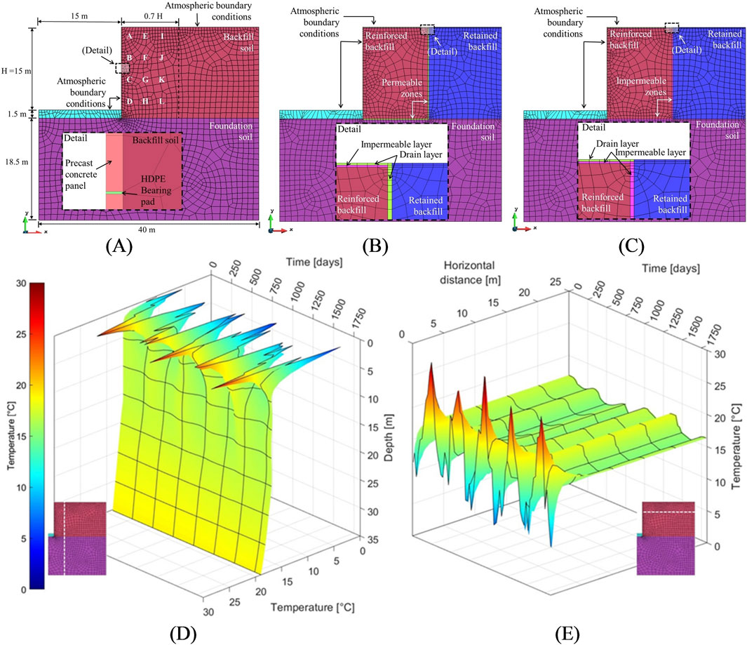
Figure 14. Finite element mesh used in the (A) exposed scenario, (B) drain contour scenario, and (C) impermeable contour scenario for the thermos-hydraulic analysis of reinforced soil walls and ttemperature-time-depth evolution of a soil profile at 5 m from the exposed (D) vertical and (E) horizontal boundary, respectively (adapted from Moncada et al., 2024b).
The use of rate-dependent constitutive models together with variable atmospheric conditions could allow to properly model the complex compound response of reinforced soil structures using varying atmospheric conditions. This is of special interest due to the possible effects of climate change. An example of the soil-atmosphere interaction is freeze-thaw cycles. This topic has already been addressed using other numerical tools in the past (e.g., Ding et al., 2023; Woo and Go, 2024) but remains to be explored using CB. While Nishimura et al. (2009) implemented the required constitutive laws within the software, no further of the use of CB for freeze-thaw simulations was found.
Further applications of the coupled formulation of CB in structural problems were not found, thus, its usefulness is yet to be proven.
8 Concluding remarks
Due to its coupled thermo-hydro-chemo-mechanical formulation, CODE_BRIGHT (CB) has ample uses in gas migration, unsaturated soils, and deep rock excavations systems, among other geotechnical problems. Having said that, CB is still amply capable of simulating civil and geotechnical engineering structures, such as reinforced soil structures, foundation systems or other compound structures. Depending on the material properties and boundary conditions, problems can require only mechanical solutions, or coupled analyses, including thermal, hydraulic, and chemical dependencies. The present work is a compilation of past research regarding the numerical modelling of reinforced soil structures, mainly reinforced soil walls, using the CB finite element software package. Modelling RSS poses several difficulties, from details such as the soil-reinforcement interface, to the overall facing displacement profile.
A bibliographic search through Scopus gave 585 publications which report the use of CODE_BRIGHT. From these results, only seven documents were related to structural modelling of reinforced soil structures, all of which focus on reinforced soil walls. Search results reveal that, while CB appears to be a well-established numerical tool, it is not yet used to simulate reinforced soil structures. Compared to other commercially available numerical tools, such as PLAXIS and FLAC, the number of articles which use CB to model reinforced soil structures is negligible. Reasons behind this can be the higher barrier of entry regarding user interface and default options compared to other commercially available software, which have a larger focus on simple user interfaces and user engagement. Other structural applications of reinforced soil, such as basal and slope reinforcements, were not found to be covered yet. Literature highlights related to the use of CB are as follow:
• A noticeable different of CODE_BRIGHT with other numerical software is the lack of material specific elements (e.g., plate and beam elements). Nevertheless, CB contains numerous constitutive models, all of which are assigned over the finite element mesh domain, providing more than enough tools to model soil and structural components.
• The use of continuum elements to simulate material interfaces, be it soil-reinforcement or soil-concrete, has showed suitable results when compared to zero-thickness elements. Continuum elements allow users to define element size, type, and material properties to the interfaces, while increasing overall node and element count and requiring the adjustment of the model geometry. Both alternatives are available in CB, as with several other commercial software.
• Full-scale models using CB were found to show adequate results, comparable to other commercially available numerical tools. No particular benefits or disadvantages to other software were observed. More complex scenarios, such as integral bridge abutments, are yet to be modelled using CB.
• The coupled formulation of CB allows to study the atmospheric effects of exposed structures, including in-soil temperature and moisture distributions. Properly assessing the effects of atmospheric variations is key when using rate dependent materials, such as geosynthetics.
Based on the available literature and to the best of the authors knowledge, CODE_BRIGHT can be a suitable tool for the numerical modelling of reinforced soil structures. If only a mechanical response is required, results are expected to be comparable with other commercially available software, without any noteworthy advantage. However, if coupled analysis are required, be it thermal, hydraulic, and/or chemical simulations, the use of CB is particularly encouraged.
Regarding future lines of research, according to the authors, the following areas could be developed, be it with CODE_BRIGHT or comparable numerical tools:
• All of the publications found were related to modelling reinforced soil walls, hence, future research and modelling attempts could be focussed on other reinforced soil applications, such as basal reinforcement (e.g., reinforced soil foundations and pavement basal reinforcement). Said structures are exposed to different stress-strain conditions than reinforced soil walls, with reinforced foundations having larger stress demands, and pavement basal reinforcement being exposed to recurring cyclic load scenarios.
• While available in CB, zero-thickness elements still remain to be tested as soil-reinforcement interfaces. Proper validation of zero-thickness elements in coupled (e.g., THM) numerical problems is encouraged, particularly for the response of soil and extensible materials (i.e., geosynthetics).
• Advance with the thermo-hydro-mechanical modelling of reinforced soil structures using coupled constitutive models for reinforcement materials subjected to varying thermal and hydraulic conditions.
• While several flux and force conditions are available, together with constitutive models with strength or stiffness degradation, currently, CB lacks options to perform dynamic analyses. Implementation of dynamic simulations is encouraged as a future line of work.
• Due to sustainability concerns, different types of fill materials (e.g., recycled construction or waste materials, marginal fills, among others) can be considered. Alternative materials can have varying mechanical, thermal, and hydraulic properties.
• Due to varying geographic locations, studies which involve structures sensitive to freeze-thaw cycles could take advantage of coupled formulation of CODE_BRIGHT.
• As with other numerical tools, being a standalone executable software, CB allows for the implementation of external algorithms to automate and iterate over numerical results. Although numerical simulations can be considerably expensive time-wise, recursive algorithms could be used to automate model calibration, validation, and prediction processes. Having said that, CB lacks design optimization tools (e.g., integrated c-phi reduction method).
Overall, numerous numerical tools are available nowadays, all of which provide comparable results. The choice of software will usually depend on user-experience and availability within the company/research centre. For standard mechanical problems, CB does not stand out as a particularly favourable or unfavourable tool. For more complex coupled problems, CB appears to be a capable and underused tool. For seismic problems, CB does not offer a viable methodology yet.
Author contributions
AM: Methodology, Writing – original draft, Writing – review and editing, Conceptualization, Investigation. ID: Writing – review and editing, Conceptualization, Supervision.
Funding
The author(s) declare that no financial support was received for the research and/or publication of this article.
Acknowledgments
The authors wish to acknowledge the support of GECO Industrial (Korea, Rep), VSL Construction Systems (Spain), the Department of Civil and Environmental Engineering (DECA) of Universitat Politècnica de Catalunya\xB7BarcelonaTech (UPC) (Spain), and the International Centre for Numerical Methods in Engineering (CIMNE) (Spain). The authors would also like to extend their sincere thanks to the reviewers during the submission process, who provided valuable feedback which substantially improved the present manuscript.
Conflict of interest
Author ID was employed by VSL International Ltd.
The remaining author declares that the research was conducted in the absence of any commercial or financial relationships that could be construed as a potential conflict of interest.
Generative AI statement
The author(s) declare that no Generative AI was used in the creation of this manuscript.
Publisher’s note
All claims expressed in this article are solely those of the authors and do not necessarily represent those of their affiliated organizations, or those of the publisher, the editors and the reviewers. Any product that may be evaluated in this article, or claim that may be made by its manufacturer, is not guaranteed or endorsed by the publisher.
References
AASHTO (2024). LRFD bridge design specifications. 10th Edn. Washington, DC, USA: American Association of State Highway and Transportation Officials AASHTO.
ABAQUS (2016). Abaqus analysis user's guide version 6.14, 2015. France: Dassault Systèmes, Simulia Corporation.
Abdelouhab, A., Dias, D., and Freitag, N. (2010). Physical and analytical modelling of geosynthetic strip pullout behaviour. Geotext. Geomembranes 28 (1), 44–53. doi:10.1016/j.geotexmem.2009.09.018
Abdelouhab, A., Dias, D., and Freitag, N. (2011). Numerical analysis of the behaviour of mechanically stabilized earth walls reinforced with different types of strips. Geotext. Geomembranes 29 (2), 116–129. doi:10.1016/j.geotexmem.2010.10.011
Abdullah, N. H. H., Ng, K. S., Jais, I. B. M., and Idrus, J. (2023). Use of geosynthetic reinforced soil-integrated bridge system to alleviate settlement problems at bridge approach: a review. Phys. Chem. Earth, Parts A/B/C 129, 103304. doi:10.1016/j.pce.2022.103304
Akbar, M., Huali, P., Huang, J., Arshid, M. U., uz Zaman Khan, Q., Guoqiang, O., et al. (2024). Seismic response comparison of various geogrid reinforced earth-retaining walls: based on shaking table and 3D FE analysis. Sci. Rep. 14 (1), 24168. doi:10.1038/s41598-024-64203-4
Alfaro, M. C., and Pathak, Y. P. (2005). Dilatant stresses at the interface of granular fills and geogrid strip reinforcements. Geosynth. Int. 12 (5), 239–252. doi:10.1680/gein.2005.12.5.239
Alonso, E. E., and Olivella, S. (2008). “Modelling tunnel performance in expansive gypsum claystone,” in Proceedings of the 12th international conference of international association for computer methods and advances in geomechanics, Goa, India, October, 2008, 1–6.
Amirhosseini, I., Toufigh, V., Toufigh, M. M., and Ghazavi-Baghini, E. (2022). Three-dimensional modeling of geogrid pullout test using finite-element method. Int. J. Geomechanics 22 (3), 04021297. doi:10.1061/(asce)gm.1943-5622.0002218
Augarde, C. E., Lee, S. J., and Loukidis, D. (2021). Numerical modelling of large deformation problems in geotechnical engineering: a state-of-the-art review. Soils Found. 61 (6), 1718–1735. doi:10.1016/j.sandf.2021.08.007
Badakhshan, E., Noorzad, A., Vaunat, J., and Veylon, G. (2024). A coupled effect of eccentric loading and upward seepage on collapse settlement of strip footings on reinforced sand. Int. J. Geomechanics 24 (8), 04024160. doi:10.1061/ijgnai.gmeng-9348
Bathurst, R. J. (2014). “Challenges and recent progress in the analysis, design and modelling of geosynthetic reinforced soil walls, Giroud Lecture,” in CD Proceedings of the 10th International Geosynthetics Conference, Berlin, 21-25 September 2014, 38.
Bathurst, R. J., and Hatami, K. (2001). “Review of numerical modeling of geosynthetic reinforced soil walls,” in Invited theme paper, Computer Methods and Advances in Geomechanics: 10th International Conference of the International Association for Computer Methods and Advances in Geomechanics, Tucson, Arizona, USA, 7-12 January 2001, 1223–1232.
Bathurst, R. J., and Naftchali, F. M. (2021). Geosynthetic reinforcement stiffness for analytical and numerical modelling of reinforced soil structures. Geotext. Geomembr. 49 (4), 921–940. doi:10.1016/j.geotexmem.2021.01.003
BS8006-1 (2016). Code of practice for strengthened/reinforced soils and other fills. Milton Keynes, UK: BSI.
Chenari, R. J., and Bathurst, R. J. (2023). Influence of geosynthetic stiffness on bearing capacity of strip footings seated on thin reinforced granular layers over undrained soft clay. Geotext. Geomembranes 51 (1), 43–55. doi:10.1016/j.geotexmem.2022.09.006
CODE_BRIGHT User’s Guide (2024). Department of Civil and Environmental Engineering, Barcelona School of Civil Engineering, Universitat Politècnica de Catalunya ·BarcelonaTech (UPC) and International Center for Numerical Methods in Engineering (CIMNE). Available online at: https://deca.upc.edu/en/projects/code_bright.
Cristelo, N., Félix, C., Lopes, M. L., and Dias, M. (2016). Monitoring and numerical modelling of an instrumented mechanically stabilised earth wall. Geosynth. Int. 23 (1), 48–61. doi:10.1680/jgein.15.00032
Damians, I. P. (2022). Modelización numérica de muros de suelo reforzado con bandas poliméricas. XI Simposio Nacional de Ingeniería Geotécnica - La Geotecnia en apoyo de la seguridad y la sostenibilidad. Escuela Politécnica de Mieres. Spain: Universidad de Oviedo, 753–778. (Available in Spanish).
Damians, I. P., Bathurst, R. J., Josa, A., Lloret, A., and Albuquerque, P. J. R. (2013). Vertical-facing loads in steel-reinforced soil walls. J. geotechnical geoenvironmental Eng. 139 (9), 1419–1432. doi:10.1061/(ASCE)GT.1943-5606.0000874
Damians, I. P., Bathurst, R. J., Olivella, S., Lloret, A., and Josa, A. (2021). 3D modelling of strip reinforced MSE walls. Acta Geotech. 16 (3), 711–730. doi:10.1007/s11440-020-01057-w
Damians, I. P., Moncada, A., Olivella, S., Lloret, A., and Josa, A. (2024). Physical and 3D numerical modelling of reinforcements pullout test. Sci. Rep. 14, 7355. doi:10.1038/s41598-024-57893-3
Damians, I. P., Olivella, S., Bathurst, R. J., Lloret, A., and Josa, A. (2022). Modeling soil-facing interface interaction with continuum element methodology. Front. Built Environ. 8, 842495. doi:10.3389/fbuil.2022.842495
Damians, I. P., Olivella, S., and Cots, C. (2018). Modelling of fibre reinforced concrete and application cases. 10th workshop on CODE_BRIGHT users. Univ. Politècnica Catalunya·BarcelonaTech (UPC).
Damians, I. P., Olivella, S., and Gens, A. (2020). Modelling gas flow in clay materials incorporating material heterogeneity and embedded fractures. Int. J. Rock Mech. Min. Sci. 136, 104524. doi:10.1016/j.ijrmms.2020.104524
Damians, I. P., Olivella, S., and Pintado, X. (2019). Three dimensional thermo-hydraulic modelling for KBS-3H alternative. Geomechanics Energy Environ. 17, 47–56. doi:10.1016/j.gete.2018.07.002
Damians, I. P., Yu, Y., Lloret, A., Bathurst, R. J., and Josa, A. (2015). “Equivalent interface properties to model soil-facing interactions with zero-thickness and continuum element methodologies,” in Proceedings of the XV Pan-American Conference on Soil Mechanics and Geotechnical Engineering (XV PCSMGE): From Fundamentals to Applications in Geotechnics, Buenos Aires, Argentina, 15th–18th November 2015, 1065–1072.
Deng, A., and Huangfu, Z. (2021). Limit state and creep behaviour of high-density polyethylene geocell. Int. J. Geosynth. Ground Eng. 7 (2), 28. doi:10.1007/s40891-021-00269-8
Ding, L. Q., Cui, F. L., and Xiao, C. Z. (2023). Numerical simulation of the performance of GRS walls considering freeze-thaw cycles. Geosynth. Int. 31 (3), 296–313. doi:10.1680/jgein.22.00368
Eldesouky, H. M. G., and Brachman, R. W. I. (2020). Viscoplastic modelling of HDPE geomembrane local stresses and strains. Geotext. Geomembr. 48 (1), 41–51. doi:10.1016/j.geotexmem.2019.103503
EN 14651 (2008). “Test method for metallic fibre concrete - measuring the flexural tensile strength (limit of proportionality (LOP), residual),” in EUROPEAN STANDARD. European committee for standardization, technical committee CEN/TC 229 “precast concrete products”.
EN 1997-3 (2025). Eurocode 7 — geotechnical design — Part 3: geotechnical structures. EUROPEAN STANDARD, ref. No. EN 1997-3, march, 2025. Brussels, Belgium: CEN European Committee for Standardization.
Fathipour, H., Payan, M., and Chenari, R. J. (2021). Limit analysis of lateral earth pressure on geosynthetic-reinforced retaining structures using finite element and second-order cone programming. Comput. Geotechnics 134, 104119. doi:10.1016/j.compgeo.2021.104119
Greenwood, J. H., Schroeder, H. F., and Voskamp, W. (2012). Durability of geosynthetics (publication 243). CUR Comm. C 187. Build. Infrastruct.
Han, H., Xiao, C., Zhu, N., and Ding, L. (2025). Effect of temperature on geogrid-soil interface performance based on pullout test. Geosynth. Int., 1–17. doi:10.1680/jgein.24.00136
Hatami, K., and Bathurst, R. J. (2005). Development and verification of a numerical model for the analysis of geosynthetic-reinforced soil segmental walls under working stress conditions. Can. Geotechnical J. 42 (4), 1066–1085. doi:10.1139/t05-040
Hsuan, Y. G., Schroeder, H. F., Rowe, K., Müller, W., Greenwood, J., Cazzuffi, D., et al. (2008). “Long-term performance and lifetime prediction of geosynthetics,” in Proceedings of the 4th European Conference on Geosynthetics, Edinburgh, September. Keynote paper.
Huang, B., Bathurst, R. J., and Hatami, K. (2009). Numerical study of reinforced soil segmental walls using three different constitutive soil models. J. Geotechnical Geoenvironmental Eng. 135 (10), 1486–1498. doi:10.1061/(ASCE)GT.1943-5606.0000092
Hussein, M. G., and Meguid, M. A. (2020). Improved understanding of geogrid response to pullout loading: insights from three-dimensional finite-element analysis. Can. Geotechnical J. 57 (2), 277–293. doi:10.1139/cgj-2018-0384
Itasca (2024). FLAC: fast Lagrangian analysis of continua, user’s guide. Minneapolis, USA: Itasca Consulting Group, Inc.
Jamshidi Chenari, R., and Bathurst, R. J. (2023). Bearing capacity of strip footings seated on unreinforced and geosynthetic-reinforced granular layers over spatially variable soft clay deposits. J. Geotechnical Geoenvironmental Eng. 149 (6), 04023034. doi:10.1061/jggefk.gteng-10889
Kaliakin, V. N., and Bathurst, R. J. (2005). Review of numerical models for geosynthetics in reinforcement applications. Comput. Methods Adv. Geomechanics 11th Int. Conf. Int. Assoc. Comput. Methods Adv. Geomechanics, Torino, Italy 4, 407–416.
Kasozi, A. M., Siddharthan, R. V., and Mahamud, R. (2015). Temperature distribution in mechanically stabilized earth wall soil backfills for design under elevated temperature conditions. J. Therm. Sci. Eng. Appl. 7 (2), 021004. doi:10.1115/1.4029354
Koerner, R. M., Lord Jr, A. E., and Halse, Y. H. (1988). Long-term durability and aging of geotextiles. Geotext. Geomembr. 7 (1-2), 147–158. doi:10.1016/0266-1144(88)90022-2
Lin, H., Gong, X., Zeng, Y., and Zhou, C. (2024). Experimental study on the effect of temperature on HDPE geomembrane/geotextile interface shear characteristics. Geotext. Geomembranes 52 (4), 396–407. doi:10.1016/j.geotexmem.2023.12.005
Luo, Z., Ding, X., Ou, Q., Zhang, T., and Zhang, X. (2025). Bearing capacity and deformation behavior of shallow footing loads on geogrid reinforced marine coral sand. Eng. Geol. 352, 108069. doi:10.1016/j.enggeo.2025.108069
Malekmohammadi, K., and Damians, I. P. (2024). A bibliometric review of reinforced soil wall research topics. Int. J. Geosynth. Ground Eng. 10, 42. doi:10.1007/s40891-024-00537-3
McGown, A., Z Andrawes, K., C Yeo, K., and Dubois, D. (1984). “The load-strain-time behaviour of Tensar geogrids,” in Polymer grid reinforcement (Thomas Telford Publishing), 11–17.
Mirmoradi, S. H., Ehrlich, M., and Magalhães, L. F. O. (2021). Numerical evaluation of the effect of foundation on the behaviour of reinforced soil walls. Geotext. Geomembranes 49 (3), 619–628. doi:10.1016/j.geotexmem.2020.11.007
Miyata, Y., Bathurst, R. J., and Allen, T. M. (2018). Evaluation of tensile load model accuracy for PET strap MSE walls. Geosynth. Int. 25 (6), 656–671. doi:10.1680/jgein.18.00032
Moncada, A., Damians, I. P., and Olivella, S. (2024a). Thermo-hydro-mechanical viscoplastic constitutive model for polyester strap reinforcement long-term response. Comput. Geotechnics 175, 106695. doi:10.1016/j.compgeo.2024.106695
Moncada, A., Damians, I. P., Olivella, S., and Bathurst, R. J. (2023). “Comparison of geosynthetic reinforced soil wall solutions using analytical design methods and numerical modelling,” in Proceeding of the GeoSaskatoon 2023 Conference – Bridging Infrastructure and Resources, Saskatoon, Canada, 1–4 October 2023, 1–8.
Moncada, A., Damians, I. P., Olivella, S., and Bathurst, R. J. (2024b). Thermo-hydraulic numerical modelling of in-soil conditions in reinforced soil walls. Geosynth. Int. 31, 808–823. doi:10.1680/jgein.23.00026
Nishimura, S., Gens, A., Olivella, S., and Jardine, R. J. (2009). THM-coupled finite element analysis of frozen soil: formulation and application. Géotechnique 59 (3), 159–171. doi:10.1680/geot.2009.59.3.159
Olivella, S., Gens, A., Carrera, J., and Alonso, E. E. (1996). Numerical formulation for a simulator (CODE_BRIGHT) for the coupled analysis of saline media. Eng. Comput. 13 (No.7), 87–112. doi:10.1108/02644409610151575
Paiva, L., Pinho-Lopes, M., Paula, A. M., and Valente, R. (2024). 3D numerical modeling of geosynthetics for soil reinforcement: a bibliometric analysis and literature review. Geotechnics 4, 673–692. doi:10.3390/geotechnics4020036
Palmeira, E. M. (2009). Soil–geosynthetic interaction: modelling and analysis. Geotext. geomembranes 27 (5), 368–390. doi:10.1016/j.geotexmem.2009.03.003
Palmeira, E. M., Araújo, G. L. S., and Santos, E. C. G. (2021). Sustainable solutions with geosynthetics and alternative construction materials — a review. Sustainability 13, 12756. doi:10.3390/su132212756
Panah, A. K., Yazdi, M., and Ghalandarzadeh, A. (2015). Shaking table tests on soil retaining walls reinforced by polymeric strips. Geotext. Geomembranes 43 (2), 148–161. doi:10.1016/j.geotexmem.2015.01.001
Perzyna, P. (1966). Fundamental problems in viscoplasticity. Adv. Appl. Mech. 9, 243–377. doi:10.1016/S0065-2156(08)70009-7
PLAXIS (2024). Reference manual, 2D - version 2024.2. Dublin: Bentley Systems International Limited. Available online at: https://bentleysystems.service-now.com/community?id=geostudio_plaxis_landing.
Ramon, A., Alonso, E. E., and Olivella, S. (2017). Hydro-chemo-mechanical modelling of tunnels in sulfated rocks. Géotechnique 67 (11), 968–982. doi:10.1680/jgeot.sip17.p.252
Ren, F., Huang, Q., Zhang, F., and Wang, G. (2024). Numerical study on seismic performance of tiered reinforced soil retaining walls. Soil Dyn. Earthq. Eng. 181, 108672. doi:10.1016/j.soildyn.2024.108672
Rocscience Inc (2025). RSWall: retaining wall analysis and design software. Available online at: https://www.rocscience.com/software/rswall (Accessed April, 2025).
Sabermahani, M., Ghalandarzadeh, A., and Fakher, A. (2009). Experimental study on seismic deformation modes of reinforced-soil walls. Geotext. Geomembranes 27 (2), 121–136. doi:10.1016/j.geotexmem.2008.09.009
Samtani, N. C., and Nowatzki, E. A. (2021). Mechanically stabilized earth (MSE) wall fills—a framework for use of local available sustainable resources (LASAR); publication No. FHWA-HIN-21-002; U.S. Department of transportation. Washington, DC, USA: Federal Highway Administration.
Segrestin, P., and Jailloux, J. M. (1988). Temperature in soils and its effect on the ageing of synthetic materials. Geotext. Geomembranes 7 (1/2), 51–69. doi:10.1016/0266-1144(88)90018-0
Shen, P., Han, J., Zornberg, J. G., Tanyu, B. F., Christopher, B. R., and Leshchinsky, D. (2020). Responses of geosynthetic-reinforced soil (GRS) abutments under bridge slab loading: numerical investigation. Comput. Geotechnics 123, 103566. doi:10.1016/j.compgeo.2020.103566
Tamayo-Mas, E., Harrington, J. F., Damians, I. P., Olivella, S., Radeisen, E., Rutqvist, J., et al. (2024). Advective gas flow in bentonite: development and comparison of enhanced multi-phase numerical approaches. Geomechanics Energy Environ. 37, 100528. doi:10.1016/j.gete.2023.100528
Tizpa, P., Chenari, R. J., and Payan, M. (2023). PFC/FLAC 3D coupled numerical modeling of shallow foundations seated on reinforced granular fill overlying clay with square void. Computers and Geotechnics 161, 105574. doi:10.1016/j.compgeo.2023.105574
Toprak, E., Olivella, S., Pintado, X., and Niskanen, M. (2024). 3D THM modelling of Finnish spent nuclear fuel repository. Front. Built Environ. 10, 1465051. doi:10.3389/fbuil.2024.1465051
Verma, H., Mishra, P. N., Manna, B., and Williams, D. (2025). Backfill-geogrid interaction: insights from pullout tests and numerical simulation. Acta Geotech., 1–22. doi:10.1007/s11440-025-02566-2
Vieira, C. S., and Pereira, P. M. (2015). Use of recycled construction and demolition materials in geotechnical applications: a review. Resour. Conservation Recycl. 103, 192–204. doi:10.1016/j.resconrec.2015.07.023
Woo, H. J., and Go, G. H. (2024). Mechanical behavior assessment of retaining wall structure due to frost heave of frozen ground. Int. J. Geo-Engineering 15 (1), 7. doi:10.1186/s40703-024-00210-8
Yu, Y., Bathurst, R. J., and Miyata, Y. (2015). Numerical analysis of a mechanically stabilized earth wall reinforced with steel strips. Soils Found. 55 (3), 536–547. doi:10.1016/j.sandf.2015.04.006
Keywords: CODE_BRIGHT, reinforced soil structures, numerical modelling, geotechnical structures, coupled analysis, geosynthetics
Citation: Moncada A and Damians IP (2025) Structural applications of CODE_BRIGHT: a review on numerical modelling of reinforced soil structures. Front. Built Environ. 11:1553500. doi: 10.3389/fbuil.2025.1553500
Received: 30 December 2024; Accepted: 30 April 2025;
Published: 19 May 2025.
Edited by:
Jie Han, University of Kansas, United StatesReviewed by:
Shaymaa T. Kadhim, University of Technology, IraqReza Jamshidi Chenari, University of Guilan, Iran
Copyright © 2025 Moncada and Damians. This is an open-access article distributed under the terms of the Creative Commons Attribution License (CC BY). The use, distribution or reproduction in other forums is permitted, provided the original author(s) and the copyright owner(s) are credited and that the original publication in this journal is cited, in accordance with accepted academic practice. No use, distribution or reproduction is permitted which does not comply with these terms.
*Correspondence: Aníbal Moncada, YW5pYmFsLm1vbmNhZGFAdXBjLmVkdQ==
†ORCID: Aníbal Moncada, orcid.org/0000-0001-5054-0513; Ivan P. Damians, orcid.org/0000-0002-0333-7296