 Cameron R. Rusnak
 Sherif A. Elfass
 Allen J. Rivas
- 1Department of Science, Technology, and Mathematics, Lincoln University Missouri, Jefferson City, MO, United States
- 2Department of Civil and Environmental Engineering, University of Nevada, Reno, NV, United States
Fire suppression piping systems utilize threaded connections to join pipes with fittings, such as elbows and tees, enabling the distribution of water throughout a structure. These fittings are essential for directional changes and navigating complex building designs. However, while prior research has examined the mechanical behavior of threaded connections at the pipe-fittings interface, limited attention has been given to the structural performance of the threaded fittings themselves. This study addresses this gap by investigating the mechanical behavior, rotational capacity, and failure modes of threaded cast iron fittings under quasistatic loading. Experimental testing was conducted at the University of Nevada, Reno, involving twenty-seven tests on elbows and tees with diameters of 1-inch, 1.5-inches, and 2-inches. The fittings were subjected to quasi-static loading to evaluate their structural response, particularly their rotational capacity and failure mechanisms. Results indicate that leakage at the pipe-fitting interface is the primary failure mode, despite significant rotation occurring within the fitting body. The average rotational capacity was approximately 28 kip-ft per radian within the fitting and 8 kip-ft per radian at the pipe/fitting interface. Additionally, larger diameter fittings demonstrated significantly reduced deformation compared to smaller fittings, with an average reduction of approximately 63% in capacity relative to the next smallest size. Based on these findings, damage states were defined, rotational capacities established, and seismic fragility models were developed for each fitting size. These results provide critical insights into the structural performance of threaded cast iron fittings, contributing to improved design guidelines and safety assessments for fire suppression piping systems.
1 Introduction
Seismic events have historically demonstrated that damage to non-structural components frequently results in greater losses than damage to structural elements, particularly in critical infrastructures such as hospitals, laboratories, and power plants. Failures in these non-structural systems not only pose significant safety risks but also hinder evacuation efforts during emergencies. Non-structural components in buildings are typically classified into architectural, mechanical, electrical, and hydraulic systems (Zito et al., 2022; Filiatrault and Sullivan, 2014; Gillengerten and Naeim, 2001). Within the mechanical category, the fire suppression piping system stands out as one of the most essential systems. A well-designed, properly installed, and diligently maintained fire suppression system plays a crucial role in minimizing losses from accidental fires, safeguarding both property and, more importantly, human life.
In the aftermath of the 1994 Northridge earthquake, Ayers & Ezer Associates conducted a comprehensive evaluation of non-structural damage, with a particular focus on pressurized piping systems, including fire sprinklers, HVAC, and domestic water systems (Fleming, 1998). Their report revealed that failures in these systems led to the evacuation of multiple hospitals and the closure of three facilities (Ayres and Ezer, 1996; OSHPD, 1995; Todd et al., 1994). Similarly, the 2010 Chile earthquake caused widespread non-structural damage across commercial, residential, industrial, and healthcare sectors, resulting in substantial economic losses. This damage affected fire suppression systems, suspended ceilings, and light fixtures (Miranda et al., 2012). Surveys conducted on 217 multistory buildings following the Christchurch Earthquake on 22 February 2011, and a post-event assessment of the 2016 Central Italy Earthquake highlighted the significant vulnerability of nonstructural components to seismic forces (Baird et al., 2014; Perrone et al., 2019). The 2011 Tohoku earthquake further emphasized the vulnerability of fire suppression piping systems, which accounted for nearly 49% of the total economic losses attributed to system failures. Reports also identified water leakage in 42% of damaged fire suppression systems. Figure 1 depicts a pie chart detailing the breakdown of fire suppression system component failures during the 2011 Tohoku earthquake (Mizutani et al., 2012).
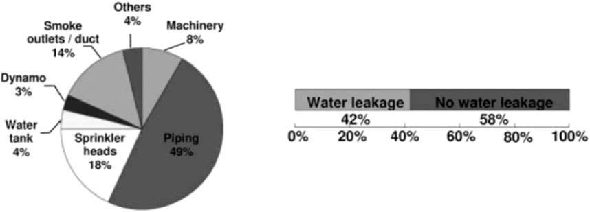
Figure 1. Fire suppression system component loss from the 2011 Tohoku earthquake (Mizutani et al., 2012).
Numerous studies have investigated the complexities of piping systems and their associated fittings. Wang et al. (2019) conducted an extensive evaluation of grooved fit joints using a quasi-static loading protocol on twelve joints to assess their seismic performance. Their findings indicated several damage states, including initial pressure drops, significant leakage, and a reduction of water pressure to 0 MPa. The observed failure modes included fractures of the grooved fittings and complete disconnections at the pipe-fitting interface. Based on these results, fragility models were developed, revealing that all joints exhibited substantial rotational capacities. Soroushian et al. (2015a) and Soroushian et al. (2015b) examined threaded and grooved-fit joints under reverse cyclic loading to determine their rotational capacities and fragility. Gutierrez and Antaki (Gutierrez and Antaki, 2012) performed a series of static and shake table tests on various pipe joint types—pressurized threaded, brazed, and mechanical—monitoring deflections and measuring loads post-testing. In a related study, Antaki and Guzy explored 16 pressurized pipe specimens featuring different tee joints using a four-point bending approach (Antaki and Guzy, 1998). Qu et al. (2018) investigated the behavior of Polypropylene Random Copolymer (PPR) pipes and galvanized steel pipes, conducting cyclic loading tests on 72 specimens to develop associated fragility curves. Sabbaghian and Mirshams (Mirshams and Sabbaghian, 2003) analyzed the failure modes of elbow tube fittings, while Zaghi et al. (2012) studied hospital piping assemblies subjected to seismic loading. Their findings showed that no leakage occurred in the welded assemblies up to a drift ratio of 4.3%, while the threaded piping experienced minor leaks at a drift ratio of 2.2%. At the University of Buffalo, Tian et al. (2013) performed an experimental seismic study on pressurized fire sprinkler piping subsystems, focusing specifically on threaded tee joints of various sizes, employing a test setup akin to that used by Wang et al. (2019). This investigation yielded insights into rotational capacities, damage states, and fragility characteristics. Rusnak et al. (2024a) highlighted the distinct performance of threaded versus welded connections in pipe fitting assemblies, emphasizing the necessity of treating threaded connections differently due to their unique mechanical and geometric properties. Yoshizaki et al. (2000) explored the behavior of buried low-angle elbow pipelines subjected to permanent ground deformation, developing a method to calculate the angle change post-deformation. Their study revealed notable differences in behavior between the closing and opening modes of the system, supported by Finite Element (FE) modeling that aligned well with the experimental results.
The investigation of threaded connections in pipes, including those formed by screws, have been a subject of prior research. Liang et al. (2018a) and Liang et al. (2018b) conducted two separate studies in July and November of 2018, focusing on the monitoring of loosening in threaded pipe connections through various techniques. In their initial study, they employed a time reversal technique combined with piezoceramic transducers to effectively monitor the loosening conditions of threaded connections. This approach demonstrated significant promise in detecting changes in joint integrity. In their subsequent study, the researchers adopted a different methodology utilizing the electro-mechanical impedance technique, further validated by both experimental and numerical analyses. The results mirrored the conclusions of their first study, reinforcing the robustness of their monitoring techniques. Additionally, Lu et al. (2019) investigated the axial forces distributed across threaded connections in bolted assemblies. Their findings, which showcased strong consistency between finite element analysis and experimental results, underscore the reliability of their conclusions and contribute valuable insights into the behavior of threaded connections under axial loading.
Historically in the United States, fire suppression systems have predominantly utilized threaded connections at the interface between pipes and fittings (Gibson and Forbes, 2001). These connections rely on the “screwing” of pipes together to achieve a water-tight seal, facilitated by National Pipe Thread (NPT) engineered threads. These threads are available in a range of pipe sizes, from a minimum of 1/8 inch to as large as 24 inches, although the latter size may not always be applicable in practice (Archtoolbok, 2023).
Despite the comprehensive guidelines established by NFPA codes (NFPA 13, 2022) and prior research on the design and performance of fire suppression systems, a gap persists in understanding the mechanical behavior of threaded cast iron fittings. Previous investigations have primarily focused on the rotational behavior and failure modes of the pipe-thread interface, often assuming the fittings to be rigid components. This oversimplification neglects the contributions of fitting deformation and rotational capacity to the overall system response, particularly under seismic loading conditions The study by Qu et al. (2018) illustrates distinct fractures in the fitting body, where the evaluated engineering damage parameter was solely the rotation at the pipe-fitting interface. This damage suggests that bending within the fitting may contribute to the observed fractures. Techniques applied in earlier works, such as those by Yoshizaki et al. (2000), WSSC (WSSC Water, 2019), and Chapman Electric Supply (Chapman Electric Supply and INC, 2024), commonly assume a rigid connection at the pipe/fitting interface, potentially overlooking the fitting’s bending influence. This gap necessitates an investigation into the performance of the fitting.
This study investigates the rotational capacity, failure modes, and seismic fragility of threaded cast iron fittings—specifically elbows and tees—across three nominal sizes (1-inch, 1.5-inch, and 2-inch diameters). A series of 27 quasi-static tests were performed to characterize the mechanical behavior of the fittings, identify critical damage states, and derive fragility curves for each size and configuration. Relevant Engineering Demand Parameters (EDPs) observed during testing were utilized to evaluate the seismic vulnerability of these connections, providing essential insights into their performance under loading conditions representative of seismic events.
2 Methodology of the quasi-static testing program on threaded cast iron pipe fittings
2.1 Threaded pipe-fitting joints
Gray threaded cast iron fittings are available in various forms, including elbows, degree bends, tees, and reducer-tees. The quasi-static testing program in this study focused specifically on elbow and tee fittings. The elbow fittings feature a 90-degree elbow joint, enabling a directional change in water flow at a right angle (refer to Figure 2A). In contrast, tee fittings comprise two 90-degree joints connected to a single pipe at the center. This design enables the smooth transition of water between distribution lines and a header line (refer to Figure 2B). All fittings were cast to adhere to the dimensions specified by Anvil and ASME standards (ASC, 2021; ASME B16.4-2016, 2016) for each nominal pipe diameter. Thread tolerances were cast in accordance with ASME standards (ASME B1.20.1-2013, 2013). The cast iron fittings are connected to carbon steel pipes, which are subsequently linked to valves and couplers. For a comprehensive understanding of the material properties of the fittings, pipes, valves, and couplers, refer to the following databases: Fitting (Matweb, 2023b), Pipe (Luz et al., 2022), and Valve/Coupler (Matweb, 2023a).
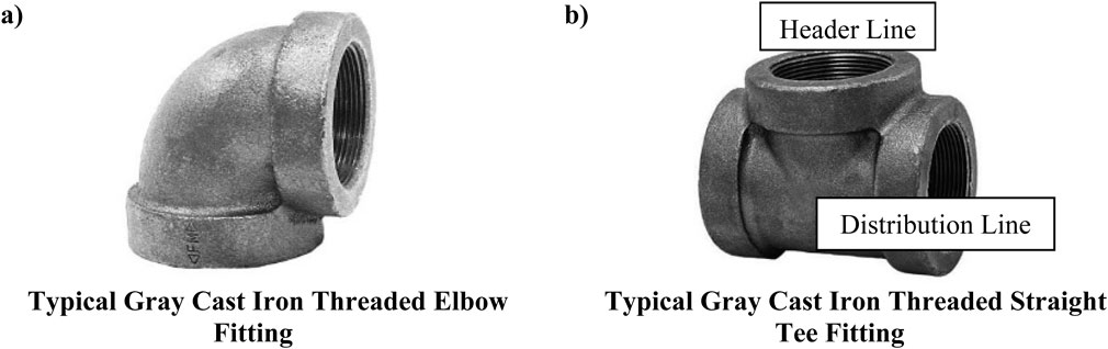
Figure 2. Typical Gray Cast Iron Threaded Connections Tested. (a) Typical Gray Cast Iron Threaded Elbow Fitting. (b) Typical Gray Cast Iron Threaded Straight Tee Fitting.
2.2 Experimental setup and loading protocol
The study involved a total of twenty-seven (27) individual tests, distributed across three (3) distinct size ranges. Each size range featured three (3) unique configurations: an elbow-pipe assembly, a tee-pipe assembly loaded from the header pipe (designated as the primary configuration), and a tee-pipe assembly loaded from one of the two distribution pipes (designated as the secondary configuration). To ensure the robustness of the results, each test configuration was repeated three (3) times, emphasizing repeatability and bolstering confidence in the results The typical test setup for each of the three (3) configurations, along with laboratory photos illustrating these configurations, is depicted in Figure 3. For clarity within this paper, P1 represents the distribution pipe connected to reinforcement Block A in the primary configuration and serves as the loading pipe in the secondary configuration. P2 refers to the header pipe loaded in the elbow configuration for the primary setup and is connected to reinforcement Block A in the secondary configuration. P3 designates the distribution pipe linked to reinforcement Block B in all tee configurations.
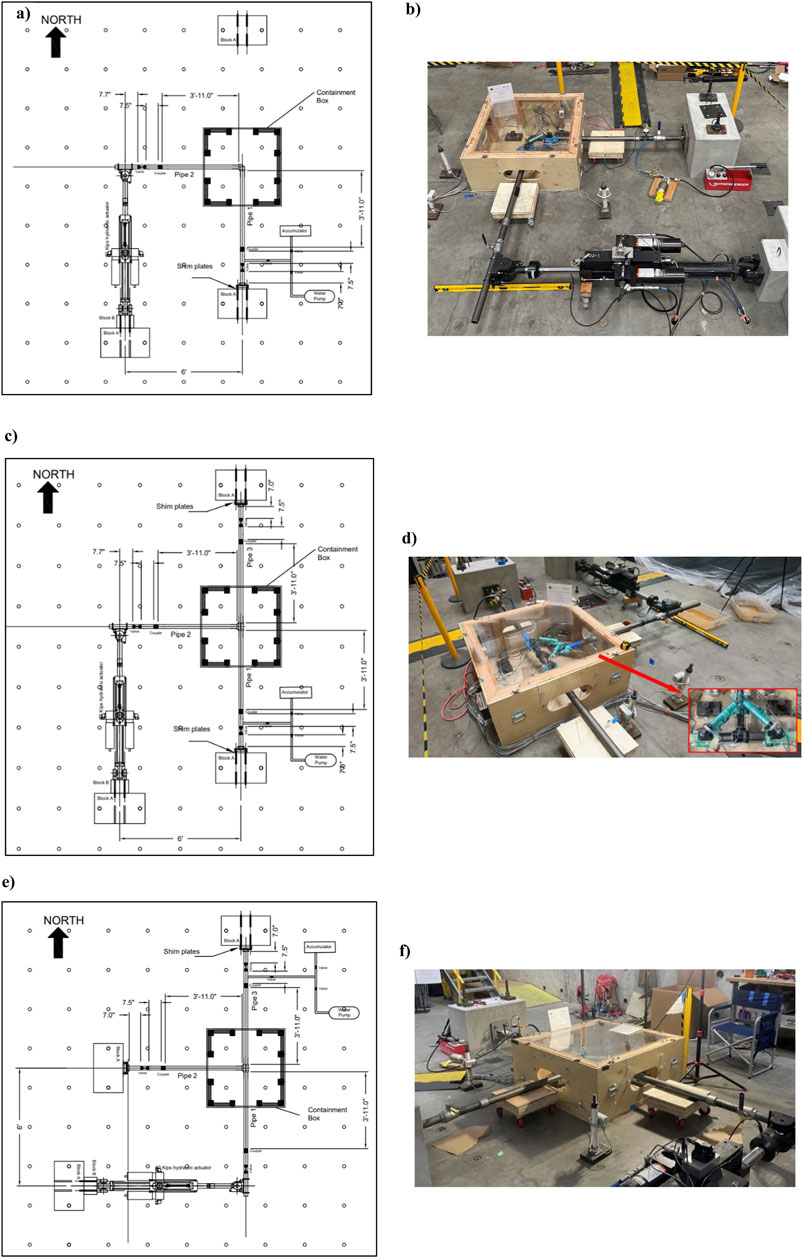
Figure 3. Test Setups and Laboratory Photos. (a) Elbow-Pipe Assembly Test Setup. (b) Elbow-Pipe Assembly Laboratory Photo. (c) Tee-Pipe Assembly in Primary Configuration Test Setup. (d) Tee-Pipe Assembly in Primary Configuration Laboratory Photo. (e) Tee-Pipe Assembly in Secondary Configuration Test Setup. (f) Tee-Pipe Assembly in Secondary Configuration Laboratory Photo.
The assemblies were mounted to a 22-kip servo-hydraulic actuator using a hinged connection, which effectively released the end moment at the loading point. This design allowed for unrestricted deflection of the assembly in the direction of loading. To provide moment support and enhance system stability, the opposite end(s) of the assembly were secured to reinforced concrete blocks, which were anchored to the floor with fixed attachments. The connection between the baseplates and the concrete blocks was secured using slip-critical bolts, ensuring no slippage occurred during experimentation. Shimming plates were incorporated at the ends of the reaction blocks to facilitate precise adjustments as necessary. Each assembly utilized a new set of pipes and fittings for every test iteration. To ensure safety during testing, a containment box was placed around the assembly. This precaution mitigated the risk of flying debris, projections, and splash hazards.
The pipe lengths on each end of the fitting were determined based on ensuring that the boundary effects from the reaction blocks, hinge supports, and servo-hydraulic actuator did not influence the observed response of the fittings. The minimum lengths were calculated to be sufficient to allow unrestricted development of the bending moment and displacement within the pipe segment without reflecting constraints back onto the fitting. While FEMA 461 (FEMA 461, 2007) does not explicitly specify minimum pipe lengths, its guidelines emphasize the importance of realistic loading conditions and minimizing artificial constraints. Consistent with these principles and prior experimental studies, the pipe lengths were chosen to be at least 10 times the pipe diameter, sufficient to prevent the boundary conditions from influencing the mechanical behavior of the fittings.
Certified Journeyman Plumbers from Deer Plumbing LLC (License # 0069124) installed the assemblies, adhering to the “skill of craft” standard commonly employed in the plumbing industry. This assembly method was chosen due to its alignment with practical installation practices typically encountered in field applications. Each assembly construction began from one of the reinforcement blocks, with pipes interconnected using a valve and coupler system. Prior to installing the fittings, a thread compound was applied to the threads of both the fitting and the pipe to ensure a watertight seal. The fittings were then tightened according to the “skill of craft” standards, followed by the systematic installation of the remaining components of the assembly. Detailed representations of the as-built structures are provided in Figure 3 for a more comprehensive understanding. While each configuration adhered to a similar assembly procedure, variations were present in dimensions such as pipe diameter, fitting size, and coupler/valve size.
Before the application of loading, each assembly underwent a hydrostatic pressure test (HPT) to verify the integrity of the construction and identify any potential leaks. The HPT was conducted after the complete assembly was finalized. During the test, pressure was maintained at 200 ± 5 psi for a continuous duration of two hours. Upon successful completion of the HPT, the pressure was subsequently reduced to the designated operating pressure of 140 ± 5 psi (NFPA 13, 2022), which was sustained throughout testing.
The reverse-cyclic testing protocol applied to the assemblies utilized a quasi-static loading approach with progressively increasing amplitudes, closely following “Interim Protocol I” outlined in FEMA 461 (FEMA 461, 2007). This protocol is specifically designed to evaluate the seismic performance characteristics of both structural and nonstructural components, facilitating the quantification of damage states and the identification of demand parameters. The testing protocol comprised 17 steps, each corresponding to distinct displacement amplitudes, with two (2) cycles performed for each displacement increment. The maximum displacement achieved during testing was 8 inches (20.32 cm). At the beginning of the 4-inch (10.16 cm) cycle, the loading rate increased from 2.5 inches (6.35 cm) per minute to 5 inches (12.7 cm) per minute, a modification implemented to reduce the overall test duration. For a detailed breakdown of the loading protocol, refer to Table 1, and a visual representation can be found in Figure 4.
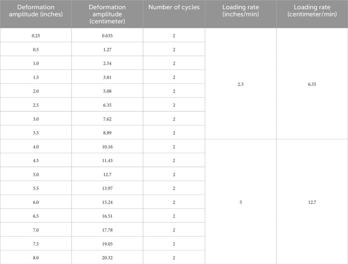
Table 1. Quasi-static cyclic test with increasing deformation amplitude.
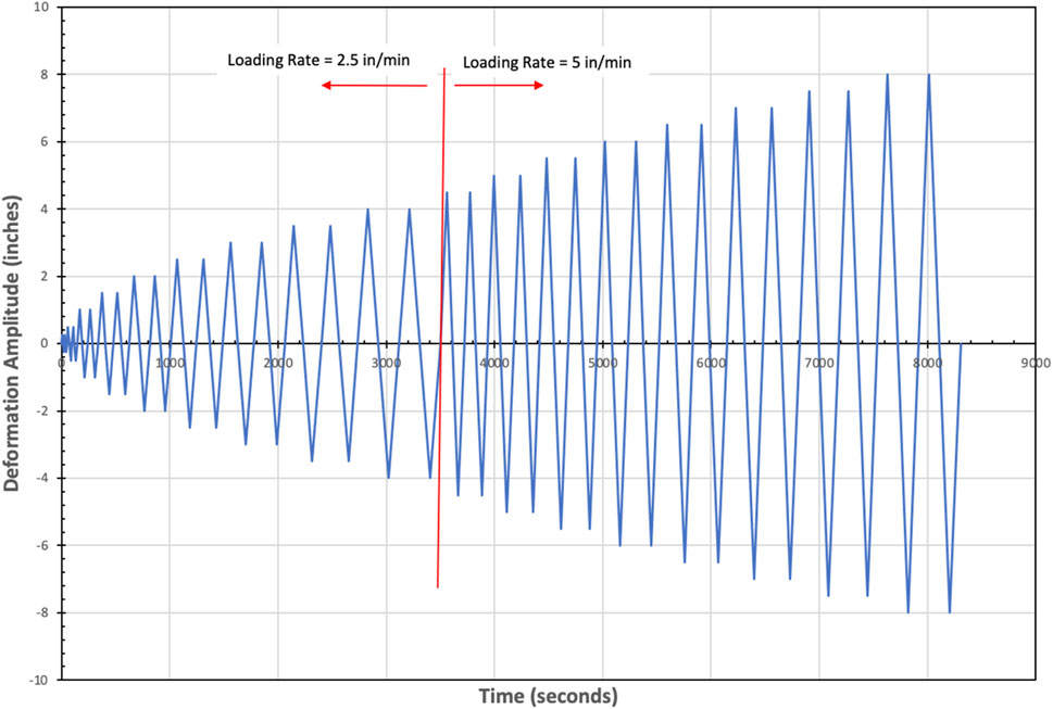
Figure 4. Graphical representation of the quasi-static cyclic test.
Testing was concluded when any of the following conditions were met:
1. Structural failure of the fitting or pipe;
2. Water leakage at the pipe-fitting interface equating to 2 ounces of water collected over the test duration; or
3. Successful completion of the loading protocol without any failure, resulting in a standard termination.
It is important to note that conditions 1 and 2 indicate a form of failure within the assembly and serve as indicators of its overall capacity. In contrast, condition 3 signifies the conclusion of the experiment without providing further insights into the assembly’s capacity.
2.3 Applicable measurements
Relevant measurements were captured using a range of sensors integrated into the National Instruments data acquisition system. These sensors were essential for monitoring various parameters, including water pressure, actuator displacement, actuator load, displacement relative to the face of the fitting, relative displacement between pipes, and the weight of the collected water.
Displacement measurements at the face of the fitting and between pipes were obtained using two distinct types of Linear Position Sensors (LPS): a standard Linear Variable Differential Transformer (LVDT) sensor and a Linear Rod Type Series (LWG) sensor. Lateral pipe rotation relative to the face of the fitting was monitored using LVDT sensors, while the LWG sensor, which was magnetically affixed to each set of perpendicular pipes, enabled the assessment of relative displacement between them. For an illustration of the typical LPS setup, focused on an elbow assembly, refer to Figure 5. It is important to note that the only significant difference between the elbow and tee configurations is the addition of a third pipe and the corresponding increase in the number of sensors.
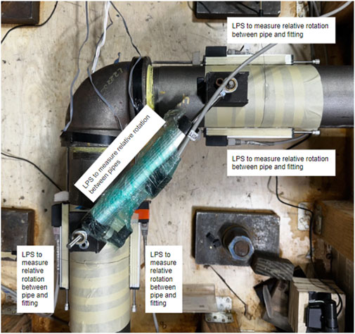
Figure 5. Typical LPS setup to capture rotation on an elbow assembly.
The actuator was equipped with internal sensors to continuously monitor both displacement and load. Water pressure was tracked using a calibrated sensor integrated into the data acquisition system, while a pressure gauge was affixed to provide a real-time visual display of water pressure during the test. To quantify any leakage, a collection pan was mounted onto a high-precision load cell positioned beneath the fitting, allowing for accurate measurement of the amount of water collected.
2.4 Applicable calculations
2.4.1 Bending moment
The bending moment (M) used to generate the results was calculated using Equation 1, where “F” denotes the load applied by the actuator and “DL” represents the applicable moment arm. Given the interest in both the rotation at the face of the fitting and the rotation of the fitting itself, two distinct moment arms were utilized. The first moment arm was defined as the distance from the center of the fitting to the loading point and was employed for the “Fitting Bending” analysis. The second moment arm was defined as the distance from the face of the fitting to the loading point and was used in the “Pipe Rotation” analysis.
2.4.2 Fitting bending calculation
The research team employed a method developed by Rusnak et al. (2024b) to calculate the bending of the fitting. This method utilizes geometric principles to comprehensively account for all rotational and bending phenomena occurring in a threaded fitting connected to pipes subjected to external forces. It provides a detailed understanding of the fitting’s rotational behavior while remaining straightforward to apply.
In this study, the rotation of the pipe relative to the face of the fitting is referred to as “pipe rotation,” while the deformation of the fitting is termed “fitting bending.” Figure 6A illustrates the deformed shape of an elbow after a “pull” cycle, while Figure 6B depicts the deformed shape following a “push” cycle. These figures represent a fitting-joint, defined as the applicable components related to pipe rotation and fitting bending, including all local pipes and the fitting itself. In the figures, the black color denotes the undeformed shape of the elbow, red represents the deformed shape post-loading, and blue indicates the variables described in the equations.
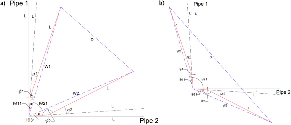
Figure 6. Deformation Shapes of an Elbow Regarding Fitting Bending. (a) Deformed Shape of an Elbow in a “Pull” Orientation. (b) Deformed Shape of an Elbow in a “Push” Orientation.
The explanation of fitting bending will reference these figures. For tee configurations, the process is reiterated using the two adjacent pipes (Pipe 1 to Pipe 2 and Pipe 2 to Pipe 3), incorporating all relevant sensors. Table 2 lists the variables used in calculating fitting bending, with values in the equations followed by the number “3” being applicable only for tees and denoted by an asterisk “*” in the equation.
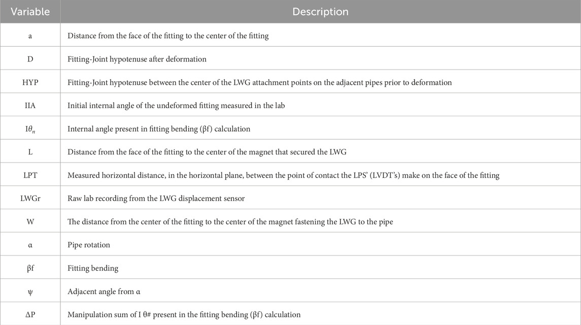
Table 2. Variables used in Fitting Bending Calculation.
The process begins with the determination of the respective pipe rotation (α) relative to the face of the fitting, as outlined in Equations 2–4*. This calculation employs two Linear Position Sensors (LVDTs) mounted on the sides of the pipes to measure the relative displacement between the fitting and the pipes. Specifically, LVDT1 and LVDT2 are positioned adjacent to Pipe 1, LVDT3 and LVDT4 adjacent to Pipe 2, and LVDT5 and LVDT6 adjacent to Pipe 3. The measured distance, denoted as LPT, is specified in Table 2. This method, analogous to the approach utilized by Tian et al. (2013), facilitates the calculation of pipe rotation.
Upon calculating the pipe rotation (α), the adjacent angle (ψ) can subsequently be determined using Equations 5–7*.
The deformed hypotenuse of the Fitting-Joint, denoted as “D,” is calculated using Equations 8, 9*. In this context, D1 represents the deformed hypotenuse between Pipe 1 and Pipe 2, while D2 corresponds to the deformed hypotenuse between Pipe 2 and Pipe 3.
The segment “W” is calculated using Equations 10–12*, derived from the angles established in Equation 5 through Equation 7*. This process is repeated for all applicable “W” distances corresponding to each fitting. The distance “L” was measured as a direct linear span, as any deviation due to bending in the pipe across this length was negligible and can be considered insignificant for practical purposes.
Geometrically, three distinct triangles are involved: triangle a-L-W1, triangle W1-W2-D, and triangle a-L-W2. From these triangles, the internal angle
At this point, the sum of “
In the final step, the calculated displacement Δ is compared to the initial internal angle (IIA). This comparison allows for the determination of the rotational bending experienced by the fitting, denoted as
3 Experimental results of the threaded cast iron pipe fittings
3.1 Physical damage of the threaded cast iron pipe fittings
Table 3 summarizes the damage observations recorded during the laboratory testing, with corresponding photographic documentation depicted in Figure 7. The predominant failure mode occurred at the interface between the pipe and the fitting, characterized by progressive water leakage that intensified throughout the testing process. Additionally, thread shearing was observed in several cases. Another significant failure mode involved structural failure localized at the reduced cross-section of the pipe threads. Water leakage was consistently noted across all three size categories and configurations, whereas structural failure was specifically observed in the 1-inch diameter tee fittings tested under the secondary configuration.
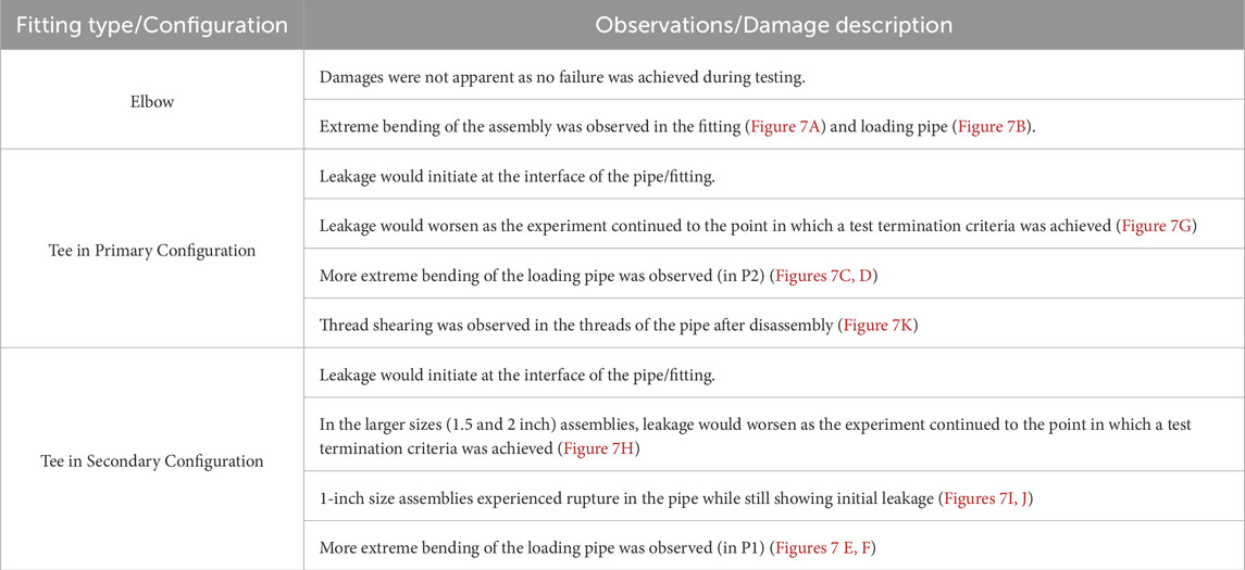
Table 3. Observed physical damages and their descriptions of the threaded cast iron fitting assemblies.
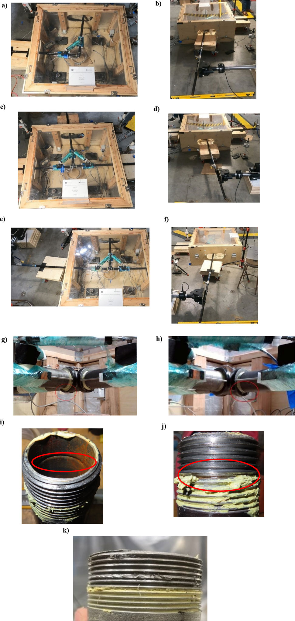
Figure 7. Observed laboratory damages. (a) Visual Deformation of Elbow Assembly (Fitting) (b) Visual Deformation of Elbow Assembly (Loading Pipe) (c) Visual Deformation of a Tee in the Primary Configuration (Fitting) (d) Visual Deformation of a Tee in the Primary Configuration (Loading Pipe) (e) Visual Deformation of a Tee in the Secondary Configuration During Testing (Fitting) (f) Visual Deformation of a Tee in the Secondary Configuration During Testing (Loading Pipe) (g) Substantial Leak Observed in the Tee Fittings (Tee in Primary Configuration) (h) Substantial Leak Observed in the Tee Fittings (Tee in Secondary Configuration) (i) 1-inch Tee Secondary Configuration Pipe Fracture (View from the Inside of the Pipe) (j) 1-inch Tee Secondary Configuration Pipe Fracture (View from the Outside of the Pipe) (k) Sheared Threads Observed After Disassembly.
3.2 Damage states and rotational capacity of the threaded cast iron pipe fittings
Three distinct damage states (DS) were defined based on the test results of the threaded cast iron fittings and are presented in Table 4. The average rotational capacities were computed for each configuration and size range, accounting for both fitting bending (rotation of the fitting) and the pipe rotation about the fitting’s face.
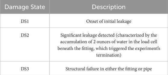
Table 4. Damage states.
All elbow fittings remained undamaged throughout testing. Figure 8A presents the calculated fitting bending rotations for the assemblies, while Figure 8B depicts the rotations of the pipe about the fitting face. Subsection (A) of both figures displays the measured rotations for the elbow tests, with the 1-inch elbow fittings demonstrating the highest rotational capacity. As the assembly size increased, the calculated rotations decreased. Tee fittings tested in both the primary and secondary configurations showed comparable rotational capacities. Damage states progressed consistently across all tee fittings, from DS1 to DS2, except for the 1-inch tees in the secondary configuration, which transitioned directly from DS1 to DS3, bypassing DS2. Subsection (B) of the figures illustrates the measured rotations for tees in the primary configuration, while subsection (C) details the measured rotations for tees in the secondary configuration. These results reflect both fitting bending and pipe rotation relative to the fitting face, offering a comprehensive view of the rotational capacities and damage mechanisms across the tested assemblies.
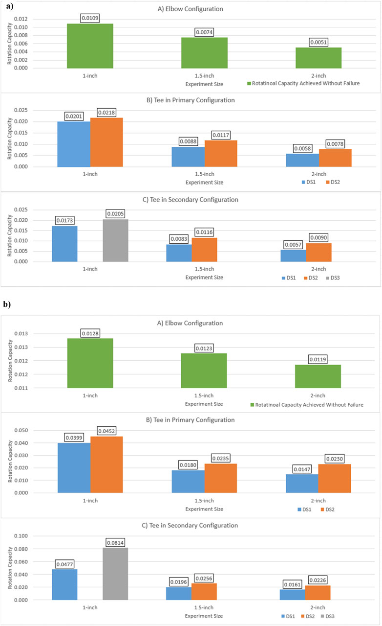
Figure 8. Measured Rotations for Assemblies Tested (A) Elbow Configuration (B) Tee in Primary Configuration (C) Tee in Secondary Configuration (Unit: rad). (a) Fitting. (b) Pipe about the Face of the Fitting.
3.3 Moment-rotation response of the threaded cast iron pipe fittings
Figure 9 displays the hysteresis loops illustrating the moment versus rotation behavior of the threaded cast iron fittings. The moment versus rotation hysteresis loops were obtained by computing the average response of the three tested specimens. Figures 9A–F, depict the response curve for the 1-inch diameter fittings, Figures 9G–L, depict the response curve for the 1.5-inch diameter fittings, and Figures 9M–R, depict the response curve for the 2-inch diameter fittings. These plots capture both the rotation of the fitting (fitting bending) and the rotation of the loading pipe about the fitting face (pipe rotation). The rotation of the loading pipe is particularly significant as it correlates directly with the onset of DS1 and DS2. Moment values were computed using Equation 1, while the corresponding rotations were determined according to the procedures described in the “Section 2.4” section. In the plots, cycles preceding any damage state are represented by solid black lines. The initiation of DS1, identified by the onset of initial leakage, is marked by a transition from the black line to a blue line. When significant leakage is detected (DS2), the test is terminated, and this is indicated by the end of the blue line, which is marked by a red star. In cases where DS2 is bypassed, leading directly to structural failure, the end of the experiment is similarly marked by a red star. Tables 5, 6 present the maximum moment, rotation, and rotational capacity for fitting bending and pipe rotation of the tested threaded assemblies. The values are presented in the imperial unit system in Table 5 and in the International System of Units (SI) in Table 6.

Figure 9. Moment-rotation response curves. (a) Moment-Rotation Response in the 1-inch Elbows (Behavior in the Fitting). (b) Moment-Rotation Response in the 1-inch Elbows (Behavior of the Loading Pipe). (c) Moment-Rotation Response in the 1-inch Tees in the Primary Configuration (Behavior in the Fitting). (d) Moment-Rotation Response in the 1-inch Tees in the Primary Configuration (Behavior of the Loading Pipe). (e) Moment-Rotation Response in the 1-inch Tees in the Secondary Configuration (Behavior in the Fitting). (f) Moment-Rotation Response in the 1-inch Tees in the Secondary Configuration (Behavior of the Loading Pipe). (g) Moment-Rotation Response in the 1.5-inch Elbows (Behavior in the Fitting). (h) Moment-Rotation Response in the 1.5-inch Elbows (Behavior of the Loading Pipe). (i) Moment-Rotation Response in the 1.5-inch Tees in the Primary Configuration (Behavior in the Fitting). (j) Moment-Rotation Response in the 1.5-inch Tees in the Primary Configuration (Behavior of the Loading Pipe). (k) Moment-Rotation Response in the 1.5-inch Tees in the Secondary Configuration (Behavior in the Fitting). (l) Moment-Rotation Response in the 1.5-inch Tees in the Secondary Configuration (Behavior of the Loading Pipe). (m) Moment-Rotation Response in the 2-inch Elbows (Behavior in the Fitting). (n) Moment-Rotation Response in the 2-inch Elbows (Behavior of the Loading Pipe). (o) Moment-Rotation Response in the 2-inch Tees in the Primary Configuration (Behavior in the Fitting). (p) Moment-Rotation Response in the 2-inch Tees in the Primary Configuration (Behavior of the Loading Pipe). (q) Moment-Rotation Response in the 2-inch Tees in the Secondary Configuration (Behavior in the Fitting). (r) Moment-Rotation Response in the 2-inch Tees in the Secondary Configuration (Behavior of the Loading Pipe).
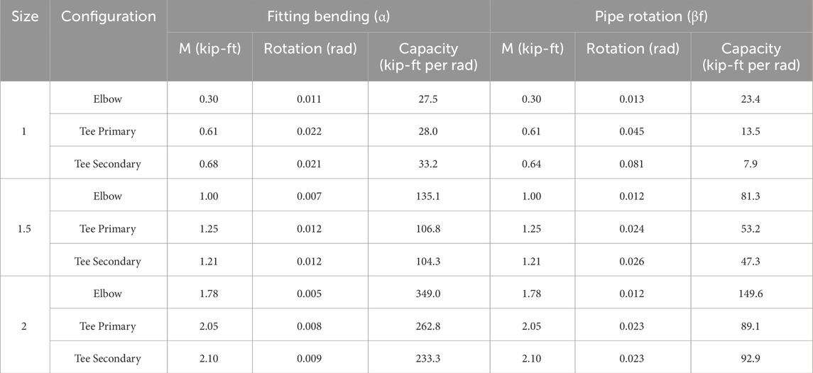
Table 5. Maximum moment, rotation and rotational capacity (imperial).
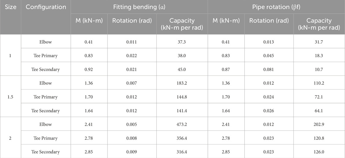
Table 6. Maximum moment, rotation and rotational capacity (SI).
3.4 Experimental fragility analysis of the threaded cast iron pipe fittings
The experimental results were processed to develop seismic fragility models for the threaded cast iron fittings. Each fragility curve was derived using three experimental tests per fitting size and configuration. The key governing factor in the fittings’ behavior, across all damage states (DS), was identified as the rotation of the loading pipe relative to the fitting face (referred to as pipe rotation), which served as the primary “Engineering Demand Parameter” (EDP). To quantify the fragility of the fittings across the defined damage states (DS1, DS2, and DS3), a methodology consistent with FEMA P58 (FEMA P58, 2018) and a method proposed by Porter et al. (2007) was applied. Fragility functions were developed for fittings that reached a damage state during testing, as illustrated in Figure 8. The fragility function, F(θ), was determined using by Equation 19, where φ represents the standard normal cumulative distribution function, θm denotes the median rotational capacity corresponding to the onset of each damage state, and β represents the logarithmic standard deviation.
Equations 20–22 are utilized to calculate both θm and β. In these equations, θi represents the i-th measured rotational capacity from a given experiment, and M denotes the total number of tests conducted within a specific size range (with M = 3 in this study). To account for the uncertainty associated with the quality of the test data—reflecting the condition of the components within the system—an uncertainty factor, βu, is introduced in the calculation of the logarithmic standard deviation. Given the limited number of experiments conducted per size range (fewer than five) and the consistent loading history experienced by all assemblies, βu was assigned a value of 0.25, in accordance with the methodology outlined in FEMA P58 FEMA P58 (2018) and Porter et al. (2007).
Table 7 provides a summary of the experimental results, while Figure 10 depict the associated fragility curves. Figures 10A–C depicts the fragility curves for the Tees tested in the primary configuration, and Figures 10D–F depicts the fragility curves for the Tees tested in the secondary configuration. It is important to note that fragility parameters and curves are not provided for the elbow experiments. This exclusion is attributed to the lack of any observed damage states in the elbow assemblies during testing, which yields a zero probability of damage state occurrence across the tested rotational capacities. It is worth noting that more tests are needed for detailed comparison to consider the influence of pipe diameter and pipe wall thickness.
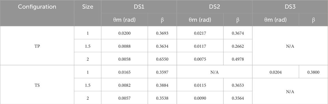
Table 7. Summary of fragility parameters.
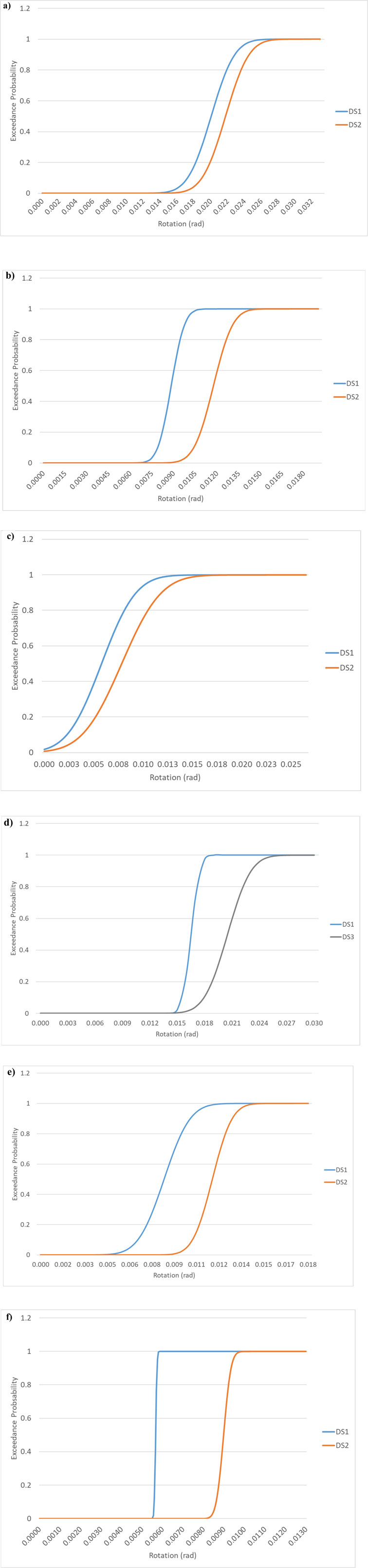
Figure 10. Fragility curves. (a) 1-inch Tee Primary Fragility Curve for Tees in the Primary Configuration. (b) 1.5-inch Tee Primary Fragility Curve for Tees in the Primary Configuration. (c) 2-inch Tee Primary Fragility Curve for Tees in the Primary Configuration. (d) 1-inch Tee Secondary Fragility Curve for Tees in the Secondary Configuration. (e) 1.5-inch Tee Secondary Fragility Curve for Tees in the Secondary Configuration. (f) 2-inch Tee Secondary Fragility Curve for Tees in the Secondary Configuration.
4 Discussion
Quasi-static tests were performed on 27 assemblies, each containing threaded cast iron fittings, to evaluate their seismic performance. This study defined three distinct damage states (DS1, DS2, and DS3), calculated rotational capacities, and developed fragility curves based on the test outcomes. The principal findings are summarized as follows:
1. The testing revealed that the predominant failure mode was leakage at the pipe-fitting interface, classified as DS1 for initial leakage and DS2 for the collection of 2 ounces of water. The secondary failure mode, identified as DS3, involved structural failure occurring within the thread channels of the pipe or in the fitting body. This structural failure was observed exclusively in the 1-inch tee under secondary configuration loading.
2. Threaded cast iron elbow fittings demonstrated no discernible damage states throughout the testing. Consequently, a probabilistic seismic fragility analysis was not performed for the elbows, as they exhibited a zero probability of experiencing any damage state during the testing conditions.
3. The calculated rotational capacities of threaded cast iron elbows do not represent their true limits, as no damage was observed during testing.
4. The maximum rotational thresholds observed across all fittings varied from 0.0057 to 0.0218 radians within the fittings and from 0.0161 to 0.0814 radians at the pipe/fitting interface. Larger fittings displayed smaller rotational capacities, while smaller assembly sizes exhibited increased capacities, with 1-inch diameter fittings demonstrating the most significant rotations prior to sustaining any damage as depicted in Figure 8.
5. Analysis of the damage states indicated that DS1 typically initiated during the “return” phase of a cycle, occurring near zero moment. This behavior can be attributed to cumulative damage accrued throughout the testing. An exception was noted with the 1-inch tees under secondary loading configurations, where DS1 was achieved, followed by an exacerbation of rotations in subsequent cycles until DS2 or DS3 was reached, ultimately leading to test termination. This trend was particularly pronounced in tees subjected to secondary loading configurations. Furthermore, the pipe rotation consistently exceeded or matched the rotation of the fitting.
6. Hysteresis loops depicting the moment versus rotation response exhibited larger rotations in smaller-sized assemblies, corroborating earlier observations. In general, the rotation of the pipe at the fitting face consistently surpassed that of the fitting itself, with the exception of elbow fittings, where the rotations were comparable.
7. The robustness of the fittings is demonstrated through both the hysteresis loops and the data presented in Tables 5, 6.
a. The hysteresis loops exhibit consistent stability across multiple loading cycles, with particular emphasis on the elbows, which did not exhibit any failure over the course of testing.
b. As shown in Tables 5, 6, the larger fitting sizes demonstrated a substantial resistance to rotational movement, as evidenced by their higher rotational capacity.
8. Larger diameter fittings exhibited a marked reduction in deformation compared to smaller fittings, with an average decrease of 75% in deformation between the 1-inch and 1.5-inch fitting assemblies, and a 52% reduction between the 1.5-inch and 2-inch fitting assemblies.
9. The logarithmic standard deviation (β) values derived from the fragility analysis quantify the inherent variability in the rotational capacities at defined damage states (DS1, DS2, and DS3). This variability accounts for uncertainties arising from material heterogeneity, manufacturing tolerances, and assembly conditions. Larger fittings exhibited higher β values, reflecting increased dispersion in their rotational thresholds, which can be attributed to greater geometric tolerances. The incorporation of β into fragility modeling enables a probabilistic characterization of system behavior, allowing for more robust seismic performance predictions and informing design practices to accommodate a range of potential demands.
10. The fragility curves presented in Figure 10 depict the relationship between pipe rotation and the probability of reaching each defined damage state (DS1, DS2, and DS3). These curves reveal that larger fittings tested exhibit lower rotational thresholds for the initiation and progression of damage, while smaller fittings demonstrate higher rotational capacities before reaching failure. Additionally, the figures underscore the variability across different configurations, with fittings in secondary configurations showing a heightened vulnerability to severe damage (DS3) when compared to those in primary configurations.
11. The developed fragility curves offer a data-driven approach to evaluating the seismic vulnerability of fire suppression systems. These models can support performance-based seismic design, guide risk assessments, and inform retrofitting strategies for critical infrastructure, such as hospitals and emergency facilities, where system failure can have severe consequences. Additionally, the fragility data provide a valuable reference for validating finite element models, helping to improve the accuracy of simulations that predict how fire suppression piping networks respond to seismic forces.
12. In comparison to previous studies on threaded cast iron fittings, such as the work by Tian et al. (2013), the fragility curves derived in this study predicted both initial and substantial leakage at larger rotational capacities. This difference can be attributed to variations in experimental setup and study focus. While Tian et al. primarily examined leakage at the pipe-fitting interface, our study accounted for the performance of the fitting itself, incorporating substantial leakage and structural failure in the fitting as distinct damage states (DS). Despite these differences, our fragility trends align with prior research, particularly the finding that larger diameter fittings exhibit lower rotational capacities at equivalent probabilities of exceedance. Additionally, limited code provisions explicitly define fragility-based performance thresholds for fire suppression fittings under seismic loading. While NFPA 13 provides design guidelines for seismic bracing, it does not establish rotational fragility limits for threaded fittings. Similarly, FEMA P58 (FEMA P58, 2018) and ASCE 7 (ASCE 7-2022, 2022) offer performance-based seismic assessment methodologies, but further work is needed to integrate fragility data from experimental studies like ours into these models.
5 Conclusion
This study demonstrates that threaded cast iron fittings in fire suppression systems exhibit significant rotational capacity, with leakage at the pipe-fitting interface emerging as the primary failure mode rather than structural failure of the fittings themselves in sizes ranging from 1-inch to 2-inch in diameter. The developed fragility curves provide a probabilistic framework for assessing the seismic vulnerability of these systems, offering critical insights for performance-based design, risk assessment, and infrastructure resilience.
The quality and mechanical performance of the fittings were assessed through their rotational capacity and failure characteristics. The maximum rotational thresholds ranged from 0.0057 to 0.0218 radians within the fittings and from 0.0161 to 0.0814 radians at the pipe/fitting interface. Larger fittings exhibited greater resistance to rotational movement but reached failure at lower rotational capacities compared to smaller fittings. The logarithmic standard deviation (β) values, ranging from 0.266 to 0.655, highlight variability in performance due to material properties and manufacturing tolerances. Notably, the observed damage thresholds exceed the conventional drift capacity limit of 2.5% of a building’s story height (ASCE 7-2022, 2022), suggesting that these fittings can accommodate substantial deformation before failure, provided they remain unconstrained. While cast iron is inherently brittle, the interaction between the pipe threads and fittings enhances system flexibility, allowing for greater resilience under seismic loading.
These findings have direct implications for engineering practice and infrastructure resilience. The observed rotational limits suggest that current design assumptions regarding fitting rigidity may need revision, particularly for seismic applications where excessive rotation could lead to leakage failures. The fragility models developed in this study provide a valuable reference for improving building codes and standards, including NFPA and ASCE guidelines, ensuring that fire suppression systems are designed with a more accurate representation of their seismic behavior.
From a research perspective, this study establishes a foundation for further investigations into the behavior of threaded fittings under different conditions, such as varying pipe materials, wall thicknesses, and internal pressure levels. Additionally, the experimental data serve as a benchmark for validating computational models, enhancing the predictive accuracy of finite element simulations for fire suppression piping networks.
Ultimately, this study challenges conventional assumptions of rigid fittings by highlighting the role of fitting deformation, rotational variability, and system flexibility in seismic performance. By integrating these insights into design, modeling, and code development, engineers can enhance the resilience of fire suppression systems, reducing failure risks and improving the safety of critical infrastructure during seismic events.
Data availability statement
The data that support the findings of this study, including test results, rotational measurements, and moment-rotation response curves for threaded cast iron fittings, are available from the corresponding author upon reasonable request. Experimental protocols, calibration data for sensors, and setup specifications are documented within the article.
Author contributions
CR: Conceptualization, Data curation, Formal Analysis, Investigation, Methodology, Project administration, Software, Supervision, Validation, Visualization, Writing–original draft, Writing–review and editing. SE: Conceptualization, Data curation, Formal Analysis, Funding acquisition, Investigation, Methodology, Project administration, Resources, Software, Validation, Writing–review and editing. AR: Data curation, Formal Analysis, Methodology, Validation, Visualization, Writing–original draft, Writing–review and editing.
Funding
The author(s) declare that financial support was received for the research, authorship, and/or publication of this article. This research received financial support from the Los Alamos National Laboratory. The opinions, findings, and conclusions presented in this paper are solely those of the authors.
Conflict of interest
The authors declare that the research was conducted in the absence of any commercial or financial relationships that could be construed as a potential conflict of interest.
Generative AI statement
The author(s) declare that no Generative AI was used in the creation of this manuscript.
Publisher’s note
All claims expressed in this article are solely those of the authors and do not necessarily represent those of their affiliated organizations, or those of the publisher, the editors and the reviewers. Any product that may be evaluated in this article, or claim that may be made by its manufacturer, is not guaranteed or endorsed by the publisher.
References
Antaki, G., and Guzy, D. (1998). Seismic testing of grooved and threaded fire protection joints and correlation with NFPA seismic design provisions. ASME Proc. Press. Vessels Pip. Div. 364, 69–75.
Archtoolbok (2023). Standard pipe dimensions. Materials and systems, plumbing. Aggregate Digital LLC. Online Article.
ASCE 7-2022 (2022). Minimum design loads for buildings and other structures. Reston, Virginia: The American Society of Civil Engineers.
ASME B1.20.1-2013 (2013). Pipe threads general purpose (inch). New York City, New York: The American Society of Mechanical Engineers. [Revision of ASME B1.20.1-1983 (R2006)].
ASME B16.4-2016 (2016). Gray iron threaded fittings, classes 125 and 250. New York City, New York: The American Society of Mechanical Engineers. [Revision of ASME B16.4-2011].
Ayres, J. M.Ezer (1996). Associates Inc. Northridge earthquake hospital water damage study, office of statewide health planning and development. Sacramento, CA: Division of Facilities Development.
Baird, A., Tasligedik, A. S., Palermo, A., and Pampanin, S. (2014). Seismic performance of vertical nonstructural components in the 22 february 2011 Christchurch earthquake. Earthq. Spectra 30, 401–425. doi:10.1193/031013eqs067m
Chapman Electric Supply, INC. (2024). Formulas for calculation conduit and pipe bends. Chapman Electric Supply, INC. A Division of Eckart Supply.
FEMA 461 (2007). Interim testing protocol for determining the seismic performance characteristics of structural and nonstructural components. Washington, D.C: Federal Emergency Management Agency. Applied Technology Council.
FEMA P58 (2018). Seismic performance assessment of buildings. Volume 1 – Methodology Second Edition. Washington, D.C: Federal Emergency Management Agency. Applied Technology Council.
Filiatrault, A., and Sullivan, T. (2014). Performance-based seismic design of nonstructural building components: the next frontier of earthquake engineering. Earthq. Eng. Eng. Vib. 13, 17–46. doi:10.1007/s11803-014-0238-9
Fleming, R. P. (1998). Analysis of fire sprinkler systems performance in the Northridge earthquake. Gaithersburg, MD: National Institute of Standards and Technology. NIST-GCR-98–736.
Gibson, D., and Forbes, I. (2001). Fire suppression in historic buildings. Cathedr. Commun. Ltd. 2019, Online Artic. doi:10.69554/VKCF8526
Gillengerten, J. (2001). “Design of nonstructural system and components,” in The seismic design handbook. Editor F. Naeim (Boston, MA: Springer), 681–721.
Gutierrez, B., and Antaki, G. (2012). “Seismic capacity of threaded, brazed and grooved pipe joints,” in ASME 2012 Pressure Vessels and Piping Conference.
Liang, Y., Feng, Q., and Li, D. (2018a). Loosening monitoring of the threaded pipe connection using time reversal technique and piezoceramic transducers. MDPI Sensors 18 (Issue 7), 2280. doi:10.3390/s18072280
Liang, Y., Feng, Q., Li, D., and Cai, S. (2018b). Loosening monitoring of a threaded pipe connection using the electro-mechanical impedance technique- experimental and numerical studies. MDPI Sensors 18 (Issue 11), 3699. doi:10.3390/s18113699
Lu, S., Hua, D., Li, Y., Cui, F., and Li, P. (2019). “Stiffness calculation model of threaded connection considering friction factors,” in Hindawi computational methods in design and manufacturing processes volume 2019. Article ID: 8424283.
Luz, G. (2022). ASTM A 106 Properties (Chem., Mech. and Ranking). Materials by Gleson Luz 2023, Online Article
Matweb (2023b). Overview of materials for Gray cast iron. Matweb Mater. Prop. Data, Online Database.
Miranda, E., Mosqueda, G., Retamales, R., and Pekcan, G. (2012). Performance of nonstructural components during the 27 February 2010 Chile earthquake. Earthq. Spectra 28, S453–S471. doi:10.1193/1.4000032
Mirshams, R., and Sabbaghian, M. (2003). Failure analysis of an elbow tube fitting. Eng. Fail. Anal. 10, 215–221. doi:10.1016/s1350-6307(02)00042-0
Mizutani, K., Kim, H., Kikuchihara, M., Nakai, T., Nishino, M., and Sunouchi, S. (2012). “The damage of the building equipment under the 2011 Tohoku pacific earthquake,” in 9th International Conference on Urban earthquake engineering and 4th Asia Conference on earthquake engineering (Tokyo: Tokyo Institute of Technology).
NFPA 13 (2022). Automatic sprinkler systems handbook. Quincy, MA: National Fire Protection Association.
OSHPD (1995). The Northridge Earthquake: a report to the hospital building safety board on the performance of hospitals. Sacramento, CA: Office of Statewide Health Planning and Development, Facilities, Development Division.
Perrone, D., Calvi, P. M., Nascimbene, R., Fischer, E. C., and Magliulo, G. (2019). Seismic performance of non-structural elements during the 2016 Central Italy earthquake. Bull. Earthq. Eng. 17, 5655–5677. doi:10.1007/s10518-018-0361-5
Porter, K., Kennedy, R., and Bachman, R. (2007). Creating fragility functions for performance based earthquake engineering. Earthq. Spectra 23, 471–489. doi:10.1193/1.2720892
Qu, Z., He, S. W., and Ye, L. H. (2018). “Seismic fragility of water supply pipelines under static and dynamic cyclic loading,” in 4th Huixian International forum on earthquake engineering for young researchers. Shanghai, China: Tongji University.
Rusnak, C., Elfass, A., and Rivas, A. (2024b). “Total rotational capacity of threaded connections in pipe-fitting assemblies,” in Pressure vessels and piping conference 2024. The American Society of Mechanical Engineers, PVP2024–123390.
Rusnak, C., Rivas, A., and Elfass, S. (2024a). “Comparison between the performance of threaded connections versus welded connections in pipe-fitting assemblies,” in ASME 2024 Pressure Vessels and Piping Conference, PVP2024–123494.
Soroushian, S., Zaghi, A. E., Maragakis, M., Echevarria, A., Tian, Y., and Filiatrault, A. (2015a). Analytical seismic fragility analyses of fire sprinkler piping systems with threaded joints. Earthq. Spectra 31, 1125–1155. doi:10.1193/083112eqs277m
Soroushian, S., Zaghi, A. E., Maragakis, M., Echevarria, A., Tian, Y., and Filiatrault, A. (2015b). Seismic fragility study of fire sprinkler piping systems with grooved fit joints. J. Struct. Eng. 141, 04014157. doi:10.1061/(asce)st.1943-541x.0001122
Tian, Y., Filiatrault, A., and Mosqueda, G. (2013). Experimental seismic study of pressurized fire sprinkler piping subsystems. Buffalo, NY: University at. (April 2013) Technical Report MCEER-13-0001.
Todd, D., Carino, N., Chung, R., Lew, H., Taylor, A., and Walton, W. (1994). Northridge earthquake: Performance of structures, Lifelines and fire protection systems, NIST interagency/internal report (NISTIR). Gaithersburg, MD: National Institute of Standards and Technology.
Wang, T., Jichao, L., Chen, X., and Li, J. (2019). Experiments and fragility analyses of piping systems connected by grooved fit joints with large deformability. Front. Built Environ. 5, 5–2019. doi:10.3389/fbuil.2019.00049
WSSC Water (2019). Water design guidelines. Part One, section 13. Rotation of fittings. WSSC, part one section 13.
Yoshizaki, K., Hamada, A., and O’Rourke, T. D. (2000). Large deformation behavior of buried pipelines with low-angle elbows subjected to permanent ground deformation. Struct. Eng./Earthquake Eng. JSCE 18 (1). 41s-52s, 2001. (J. Struct. Mech. Earthquake Eng., JSCE, No. 675/I-55. doi:10.2208/JSCEJ.2001.675_41
Zaghi, A. E., Maragakis, E. M., Itani, A., and Goodwin, E. (2012). Experimental and analytical studies of hospital piping assemblies subjected to seismic loading. Earthq. Spectra 28, 367–384. doi:10.1193/1.3672911
Zito, M., Nascimbene, R., Dubini, P., D’Angela, D., and Magliulo, G. (2022). Experimental seismic assessment of nonstructural elements: testing protocols and novel perspectives. Buildings 12 (11), 1871. doi:10.3390/buildings12111871
Appendix A
To assist readers in interpreting the results, the following table (Table A1) provides conversions between imperial and SI units for the key parameters used in this study.
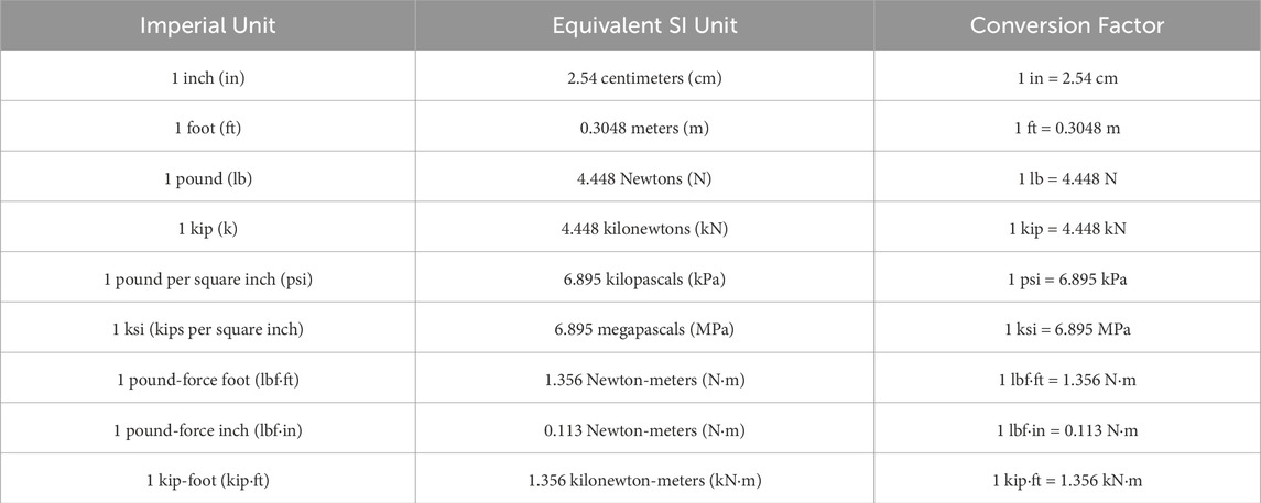
TABLE A1. Unit Conversion Table.
Keywords: piping system, threaded cast iron pipe fitting, rotational capacity, quasi-static testing, damage states, probabilistic seismic fragility analysis
Citation: Rusnak CR, Elfass SA and Rivas AJ (2025) Experimental and fragility analysis of threaded cast iron pipe fittings utilized in a fire suppression system. Front. Built Environ. 11:1565894. doi: 10.3389/fbuil.2025.1565894
Received: 23 January 2025; Accepted: 04 March 2025;
Published: 28 April 2025.
Edited by:
Roberto Nascimbene, IUSS - Scuola Universitaria Superiore Pavia, ItalyReviewed by:
Chaminda Senarathne Bandara, University of Peradeniya, Sri LankaDanilo D’Angela, University of Naples Federico II, Italy
Copyright © 2025 Rusnak, Elfass and Rivas. This is an open-access article distributed under the terms of the Creative Commons Attribution License (CC BY). The use, distribution or reproduction in other forums is permitted, provided the original author(s) and the copyright owner(s) are credited and that the original publication in this journal is cited, in accordance with accepted academic practice. No use, distribution or reproduction is permitted which does not comply with these terms.
*Correspondence: Cameron R. Rusnak, cnVzbmFrY0BsaW5jb2xudS5lZHU=