 Jason T. DeJong1*
 Daniel W. Wilson1
 Alejandro Martinez2
 Katerina Ziotopoulou2Soo-Min Ham2
 Ross W. Boulanger2
- 1Department of Civil and Environmental Engineering, Center for Geotechnical Modeling, University of California, Davis, CA, United States
- 2Department of Civil and Environmental Engineering, University of California, Davis, CA, United States
The Natural Hazards Engineering Research Infrastructure facility at the University of California at Davis (UC Davis) is equipped with 9-m- and 1-m-radius geotechnical centrifuges that provide unique, world-class facilities for scaled modeling of complex systems. This national, open access research facility allows scientific and engineering communities to realize major advances in understanding, predicting, and improving the performance of civil infrastructure and natural systems. Large-scale centrifuge modeling of systems-level problems is particularly effective in advancing fundamental knowledge, upscaling and testing new technologies at the prototype scale, developing engineering analysis and design methods, and validating advanced computational models. The capabilities and unique role of large-scale centrifuge modeling are illustrated through four example research projects. These are followed by a discussion of envisioned future research directions and opportunities on how hypergravity modeling can be used to address natural and anthropogenic-induced loadings on civil infrastructure and natural systems.
1 Introduction
1.1 UC Davis Centrifuge facility
UC Davis has been operating geotechnical centrifuges for 5 decades, with the 1-m centrifuge acquired in 1975 and the 9-m centrifuge installed in 1986. The Center for Geotechnical Modeling (CGM) was established in 1983 to develop and manage the 9-m “National Geotechnical Centrifuge.” The CGM continues to operate the centrifuges as a national shared-use facility that is accessible to any researcher requiring hypergravity to execute their research program. The 1-m centrifuge can subject ∼50 kg of soil (container ∼178 mm deep, ∼560 mm long, and ∼280 mm wide) to a centrifugal acceleration of 100 g. The 9-m centrifuge can subject ∼1,550 kg of soil (container ∼686 mm deep, ∼1,722 mm long, and ∼686 mm wide) to a centrifugal acceleration of 80 g, representing prototype soil depths of up to ∼50 m. Both centrifuges are equipped with shaking tables that enable the simulation of earthquake-like ground motions, the designs of which have been replicated at many other facilities. A more detailed discussion on the history of the facility, including the important developments enabled by the National Science Foundation (NSF) Network for Earthquake Engineering Simulation (NEES) equipment award, is detailed in Boulanger et al. (2020).
The pair of CGM centrifuges are used synergistically to support hypergravity research. The 9-m centrifuge containers enable sensor-dense, detailed, complex models that provide high fidelity measurements of system performance. These large experiments often have more than 120 sensors and require months of effort from the start of model building through test completion. In contrast, the smaller 1-m centrifuge can prove advantageous for parametric exploration of mechanisms where a low sensor count and small model size are appropriate and time efficient. Here, tests can be completed in a few days. Researchers also often choose to perform 1-m tests to refine designs and train personnel for upcoming 9-m tests. To support this synergistic use, the CGM manages the two centrifuges to operate as similarly as possible from sensor inventory to model building and loading protocols and resources.
The systems investigated by researchers and the characteristics of the tests have evolved with time as research interests have diversified and new testing capabilities have been developed. To date, more than 100 separate research projects, with a total funding of more than $100M (2024 USD), have used the CGM, each performing one to dozens of centrifuge tests on the 1-m and/or 9-m centrifuges. The development of servo-hydraulic shaking tables in the 1980s and 1990s and the uniquely large model container size of the 9-m centrifuge allowed making advances in seismic applications, and to this day it remains one of only two centrifuges worldwide able to subject models with over 1,500 kg of soil to seismic motions. Consequently, up until the 2010s the majority of centrifuge research programs at the CGM focused on problems related to geotechnical earthquake engineering, with topics including liquefaction (triggering, lateral spreading, levee/embankment deformations, quay wall deformations), ground improvement (densification, drainage, grouting, soil-cement reinforcements), soil-structure interaction (shallow and deep foundations in soft or liquefiable soils for buildings, bridges, tanks, wharves, quay walls), buried structures (lateral pressures and kinematic demands on basements, culverts, subway tunnels and stations), seismic site response (sands, soft clays, organic soils), mechanically stabilized earth retaining walls, geosynthetic liner systems for waste containment, and water-structure-soil interaction for buried reservoirs. Common test characteristics drove numerous developments, including sand model construction techniques (e.g., Stringer et al., 2014), saturation with viscous fluids (e.g., Stewart et al., 1998), dense sensor arrays (e.g., Wilson et al., 2002), scaling and design of structure models (e.g., Kutter and Wilson, 2006), and scaling of ground motions (e.g., Mason et al., 2010), as well as associated data analysis and interpretation techniques (e.g., Kutter and Balakrishnan, 1998; Wilson and Almond, 2014).
The breadth of research topics being performed at the CGM has recently expanded to address new engineering challenges, shifts in national research priorities, diversification of researcher interests, and the now established efficacy of centrifuge modeling based on successful past projects. This expanding breadth includes offshore foundation systems (wave, wind, and seismic loading of jacket structures, suction caissons, subsea manifolds, anchors; e.g., Litton et al., 2014; Huang et al., 2024), in-situ characterization of challenging soils (gravelly soils, intermediate soils, mine tailings, fly ash, interbedded soils; e.g., Carey et al., 2022; Price et al., 2019; Madabhushi et al., 2023; Chen and Martinez, 2025; Khosravi et al., 2022, respectively), and tsunami effects on coastal stability (e.g., Exton et al., 2019). Associated with this diversification of research topics have been corresponding developments in modular hydraulic and electro-mechanical actuation systems, including CPT (Carey et al., 2018) and full-flow in situ penetrometers, foundation installation hammers and screw-in techniques (Martinez and O’Hara, 2021); advanced soil preparation techniques for clays, intermediate soils, and gravels (Sturm, 2019); novel embedded and non-contact sensors for measuring soil response and system deformations (e.g., Sinha et al., 2023a); and systems to evaluate the effect of drainage and rewetting on soil response (Chen and Martinez, 2025). Since 2010, the growth of biogeotechnics has led to biomediated (microbially-induced calcite precipitation, microbially-induced desaturation and precipitation; e.g., Darby et al., 2019; San Pablo et al., 2024; Hall et al., 2018) and bioinspired (e.g., snakeskin-inspired piles, tree root-inspired anchors; e.g., O’Hara and Martinez, 2022; 2024; Kim et al., 2024) research projects, which have driven new developments in prototype fabrications using 3D printers, sensors for partially saturated conditions, and model construction protocols with finite improved zones (e.g., Ham et al., 2024b). These experiences have demonstrated that capability development for hypergravity testing is often effectively achieved through the pursuit of new research topics where researchers can “champion” advances in partnership with the CGM.
1.2 Scaled hypergravity modeling
The hypergravity field imposed during a centrifuge test allows for stress similitude between the model and full-scale prototype, such that the response of a scaled centrifuge model to different loadings is representative of the response expected under field-scale conditions. For example, the profile of vertical effective stress in a 0.5-m-high embankment at 100 g is equivalent to the profile of vertical effective stress in a 50-m-tall embankment in the field (i.e., at 1g). Centrifuge modeling offers similarity advantages for physical processes where self-weight body forces are important, including various porous media, fluid, and gas related phenomena (e.g., Taylor, 1995). Scaling laws and equations of similitude have accordingly been developed for a wide range of physical phenomena (e.g., Schofield, 1981; Kutter, 1995; Garnier et al., 2007).
The use of scaled hypergravity modeling creates an accessible research domain that is expansive and arguably provides a larger parameter space to explore than is possible in 1g model space or in the field, as indicated in Figure 1. In this figure the “field space” domain represents the breadth of conditions present in the built and natural environments. The “field data” is a subdomain of the “field space” where the built and natural environment has been observed and the characteristics and behaviors have been captured through quantitative measurements for scientific and engineering purposes. The ability to capture measurements for critical conditions, such as in post-disaster reconnaissance efforts, is limited, as much of the critically valuable information is time-sensitive (perishable) or is not accessible (due to the lack of monitoring systems and limited post-event investigations) (e.g., Bray et al., 2019; Wartman et al., 2020). Simulations of realistic conditions in the lab in “1g model space” for soils and other stress-dependent materials is challenging as soil stiffness, strength, and dilatancy are all directly dependent on the effective confining stress. The domain space where 1g modeling of shallow geotechnical systems may be realistic (i.e., fall within the broader “field space”) is relatively small, while scaled modeling of more complex systems in 1g models, such as deep foundations, is realized in a parameter space that exists outside the domain observed in the field for the built environment. Nonetheless, 1g scaled modeling can be used successfully when accounting for how the effective stress profile in the model influences the stress-dilatancy response of sand and the undrained strength profile in clay (e.g., LeBlanc et al., 2010; Bradshaw et al., 2016).
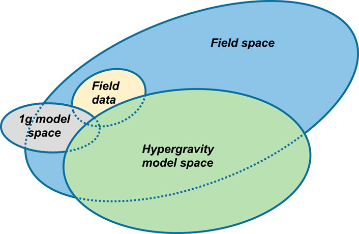
Figure 1. Schematic indicating the overlap and interrelationships between the real built and natural environment (“field space”), the subset of real space where data is collected (“field data”), and the accessible domain at 1g (“1g model space”) and using hypergravity (“hypergravity model space”).
The “hypergravity model space,” including the effective use of the scaling relationships, provides the opportunity to more accurately model a larger portion of the domain of full-scale field conditions that exist in the natural and built environments (indicated by large overlap with “field space”) and to explore a broad range of conditions that may not exist in the natural environment (i.e., outside the field space). This enables two approaches in the design of a research program. Commonly, the hypergravity environment and scaling laws are used to model field-scale systems with reasonable accuracy, following best practices in applying model scaling laws (e.g., Schofield, 1981; Kutter, 1995; Garnier et al., 2007) and appropriately managing aspects that cannot be scaled exactly. Alternatively, the hypergravity environment allows the gravitational field to be activated as another test variable, where experiments can be designed to ensure that representations of bio-thermo-hydro-chemo-mechanical processes, as often posed in dimensionless groups, have appropriately captured the effect of the gravitational field on the phenomenon being investigated. The former is more often used when researching the built environment, while the latter can be an effective tool for examining fundamental processes. Collectively, this makes the hypergravity environment an effective research tool for advancing knowledge in engineering and science.
1.3 Research approach to experimental design and validation of numerical simulations
Hypergravity experiments can be particularly effective in advancing fundamental knowledge, upscaling and testing new technologies at the system prototype scale, developing engineering analysis and design methods, and validating advanced computational models. Figure 2 illustrates the process through which a hypergravity experiment may be designed and the generated results used to advance analysis and design methods or validate advanced computational models.
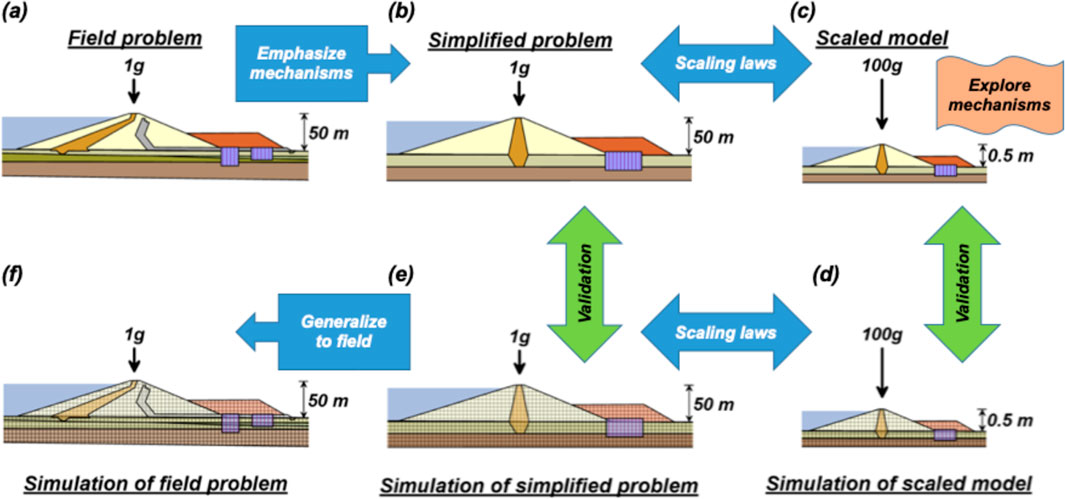
Figure 2. Workflow approach from (a) the specific field problem, to (b) a simplified problem that emphasizes the critical mechanisms, to (c) a scaled model that is explored through hypergravity modeling, to simulations of the hypergravity test to validate the numerical simulations at either (d) Ng or at (f) 1g, and then (f) the translation of the validated model to the motivating project field problem.
Consider a hypothetical full-scale 50-m-high embankment dam with a complex cross-section, a newly identified seismic risk from liquefaction susceptibility of an alluvial foundation deposit, and an extensive proposed seismic remediation scheme (Figure 2a). An engineer performing analyses on this complex section (Figure 2f) may face questions regarding the reasonableness of their analysis due to a lack of physical data for validating their numerical model, especially given limited understanding of fundamental interaction mechanisms for many remediation schemes. To address this, the complex system with its proposed improvements can be acceptably simplified for study by retaining mechanisms critical to seismic system behavior and simplifying features that do not control the mechanisms being investigated (Figure 2b). A reduced-scale physical model of the simplified problem (Figure 2c) is built following the scaling laws and tested by subjecting it to various seismic loads to explore the critical mechanisms. Scaling laws can then be used to express the observed physical behaviors at real-world (i.e., prototype) scale for easy comparison with field-scale experiences. The engineer can then analyze the simplified problem using design tools to verify that they accurately capture critical behaviors. This comparison can be performed at 1g or Ng (Figures 2e,d, respectively). Comparisons at 1g are easier to compare to real-world systems while comparisons at Ng directly capture the physics and can avoid potential conflicts in scaling laws. Finally, the engineer can generalize their analysis to the field problem, translating their validated understanding and analysis techniques to the specific project of interest (Figure 2f) with confidence.
1.4 Overview of paper
The UC Davis Center for Geotechnical Modeling has been described as a national, open access research facility with the 1-m and 9-m centrifuges. A brief history was presented, and general concepts of hypergravity modeling were introduced. In the remainder of this paper, four examples are used to highlight the breadth of research programs supported by the facility in the past 5 years, including renewable energy systems, pile performance in liquefiable soils, large deformation flow problems, and advancement of biogeotechnical technologies. Finally, envisioned future research directions and opportunities related to natural and anthropogenic-induced loadings on the civil infrastructure and natural systems using the facility are broadly discussed.
2 Research example: renewable energy systems–shared mooring configurations for anchors for offshore wind turbines
The energy harnessed from renewable and sustainable sources, such as solar, wind, and thermal, has increased significantly during the last two decades. About 10% of the energy in the US is now produced from onshore wind (United States Energy Information Administration, 2024). Meanwhile, offshore wind (OW) offers significant potential advantages over onshore. Wind resources are stronger and more consistent offshore, and offshore deployments do not occupy valuable land. In Europe, 28GW of OW energy have been installed as of 2021 (Komusanac et al., 2022), while the US has committed to installing 30GW by 2030 (United States Department of Energy, 2021). Despite its benefits, the cost of OW energy is high compared to other renewable sources due to the cost of installation of the turbines and supporting infrastructure. A key opportunity to improving the cost competitiveness of OW energy is decreasing the cost of the turbine foundations, which can account for 25%–35% of the total construction cost (DNV, 2023).
Approximately 65% of the US’ wind resources are in deep water locations where floating offshore wind turbines (FOWTs) are required. In FOWTs, the turbine is maintained in position by subsea anchors and mooring lines. Conventionally, each turbine is connected to three anchors and each anchor is connected to only one turbine. One emerging alternative for reducing the cost of FOWTs is to use a shared mooring configuration where each subsea anchor is shared by three turbines (i.e., each turbine connected to three anchors, each anchor connected to three turbines), as described in Fontana et al. (2018). Anchor sharing can reduce the number of anchors by up to a factor of three in comparison with the conventional configuration. Meanwhile, a recently developed ring anchor design offers additional potential benefits over common types of FOWT anchors such as driven piles, suction caissons, and plate anchors (Aubeny, 2017), due to its compact size which can simplify shipping and installation logistics, deep embedment which provides a high capacity, and symmetric geometry which is amenable to shared configurations (Lee et al., 2020). Figure 3 depicts the installation process and loading of a shared ring anchor.
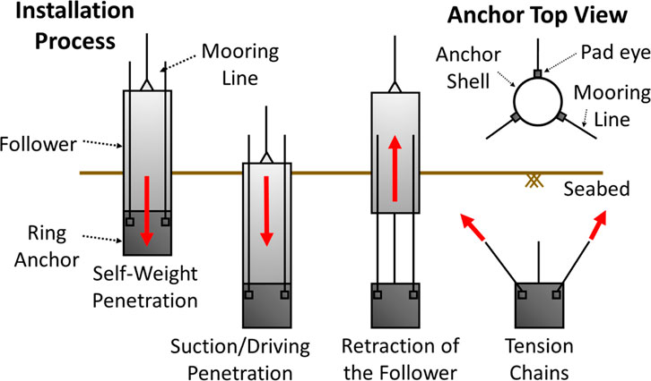
Figure 3. Schematic of the installation process and loading of a ring anchor.
Despite the compelling economic and efficiency arguments of shared anchor configurations, research is required because shared anchors are subjected to more complex loading conditions than conventional anchors. Specifically, the individual vertical loads from the three turbines add up, while having multiple turbines connected to a single anchor can lead to changing horizontal load direction which can reduce the soil’s strength and stiffness. These complexities are in addition to the cyclic environmental loads from the wind, waves, and tides, which also introduce considerable uncertainty in creating stable designs.
Given the remote location of offshore wind turbines and their very large size, load testing to verify anchor or foundation capacity is in most cases unfeasible. Centrifuge testing provides an opportunity to systematically examine the response of anchor and foundation systems in conditions that are representative of the field. This enables investigation of the effect of factors such as soil strength and stiffness, embedment depth, and geometry on short- and long-term anchor stability. Centrifuge testing can also be used to verify the behavior of existing and newly developed anchor and foundation technologies, as presented here for the ring anchors. At the UC Davis CGM, equipment has been developed to test subsea anchors in shared and conventional configurations. Specifically, a system capable of applying loads to a buried anchor has been built to perform tests at gravities as high as 70g. This system is composed of three electromechanical actuators that can be controlled in sync to apply representative loads from three individual FOWTs. This system is shown in Figure 4a, showing a buried anchor in a soil deposit being loaded by the three actuators simultaneously. Each actuator can be programmed to produce specific monotonic or cyclic loads. The actuators can apply up to 8 kN in model scale to simulate environmental loads, which is equivalent to 39 MN in prototype scale at 70g. The force and displacement of each line are measured with load cells and linear potentiometers, while the evolution of the line angle is measured with inclinometers. The steel wires connecting the actuators to the buried anchors have a nylon coating to reduce the friction with the soil. This actuator system can also be configured to test anchors in a conventional, non-shared configuration, in which an anchor is loaded by an individual actuator, as shown in Figure 4b.
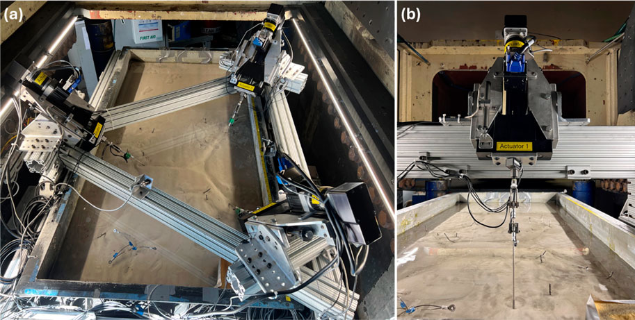
Figure 4. Photographs of the actuator system built for load testing (a) shared and (b) not shared anchors in the 9-m centrifuge.
The loads applied to the anchors during centrifuge load tests were determined using numerical simulations of reference FOWTs and load cases representative of specific locations off the coast of California, as described in detail in Davis (2023) and Coughlan (2024). Monotonic and cyclic load tests have been performed on ring anchors in deposits of sandy and clayey soils. These tests have characterized the effect of parameters including the line angle, out of plane angle, embedment depth, and magnitude of static and cyclic loads on the ultimate capacity and accumulation of displacements of ring anchors. Figure 5a shows the cyclic loads applied to an anchor in a clay deposit under a Service Limit State (SLC) scenario, indicating precise control of the actuators. Figure 5b shows the position of the anchor during application of the loads, showing that as the load out of plane angle (i.e., on the horizontal plane) is changed, the anchor’s displacement evolves accordingly. The figure shows the progressive loss of embedment of the anchor, which should be taken into consideration in assessing long-term stability.
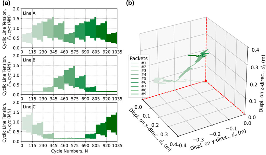
Figure 5. Results of a cyclic load test on a shared anchor: (a) applied line loads and (b) evolution of anchor displacement.
Centrifuge testing has been essential in verifying the performance of the novel ring anchor under static loads at varying line angles (Huang et al., 2024; 2025b), and current work is assessing the stability of ring anchors subjected to cyclic loads (Huang et al., 2025a). The satisfactory performance of the ring anchors in centrifuge tests has helped their Technology Readiness Level (TRL) to advance to “field testing in the near future” (i.e., Level 6). Continued developments for testing of offshore wind energy applications in the centrifuge will include expansion of actuator systems to apply different types of loads, assessment of seismic events on anchor and foundation stability using the centrifuges’ shake tables, and evaluation of the effect of different installation methods on the response of anchors and foundations.
3 Research example: soil-structure interaction–response of axially loaded piles under post-liquefaction reconsolidation downdrag
Many bridges, critical to transportation infrastructure, are constructed at sites with underlying layers of liquefiable sand. During earthquakes, these sands can liquefy and subsequently reconsolidate, causing significant ground settlement. To prevent excessive bridge settlement and to resist the accompanying downdrag forces on foundation piles, engineers typically extend these piles through the liquefiable layers to reach stronger, deeper soil strata. Determining appropriate pile dimensions presents a challenging optimization problem. Engineers must account for both the bridge’s weight and the substantial downdrag forces that develop as settling soil generates downward friction along the pile shaft. This combined loading must be safely transferred to the soil surrounding the pile tip. However, increasing pile diameter to increase load carrying capacity at depth also increases the induced downdrag force by increasing the pile’s surface area where the soil liquefies and settles. These increased forces then require longer piles to reach deeper bearing layers, significantly increasing construction costs. This interdependency between pile dimensions and downdrag forces has long been a critical design issue affecting bridge economics.
Research and practice have offered several approaches to analyze pile behavior during and/or after liquefaction (e.g., Boulanger and Brandenberg, 2004; Rollins and Strand, 2007; Fellenius and Siegel, 2008; Hannigan et al., 2016; Muhunthan et al., 2017). The simplest are force-based analyses, which, while straightforward, neglect the displacements of the soil and pile. More sophisticated load-transfer methods (e.g., neutral plane methods) incorporate various factors like skin friction mobilization and modify soil spring properties to account for liquefaction effects, though they fail to capture the problem’s dynamic nature. Fully coupled nonlinear dynamic analyses (NDAs) can model the underlying mechanisms but often lack experimental validation. Regardless of the analytical approach chosen, fundamental uncertainties persist regarding three critical aspects: the temporal evolution of excess pore pressure (both generation and dissipation), the reduction and subsequent recovery of shaft friction at the soil-pile interface, and the mechanical response of the pile tip under these conditions. An extensive research program was pursued at the CGM, starting with large-scale dynamic centrifuge model tests and followed by the development and validation of advanced numerical analyses and the development of a design framework that overall advanced the profession’s understanding of this problem (Sinha et al., 2023b).
To investigate pile behavior under liquefaction-induced downdrag, Sinha et al. (2021a); Sinha et al. (2021b) performed two comprehensive series of tests using the 9-m centrifuge. The experiments utilized 1/40th-scale models tested at 40 g centrifugal acceleration to accurately simulate full-scale field conditions. The model configurations consisted of heavily instrumented closed-ended aluminum pipe piles, which at prototype scale represented 635-mm-diameter piles. The first test series (Sinha et al., 2021a; 2022a), shown in Figure 6a, examined a simplified soil profile: a liquefiable loose sand layer sandwiched between a low-permeability clay crust above and a dense sand bearing layer below. The second series (Sinha et al., 2021b; Ziotopoulou et al., 2022), shown in Figure 6b, featured more complex soil stratigraphy to better represent typical field conditions. Throughout both series, the loose sand layers were prepared at relative densities between 40% and 45% to simulate highly liquefiable conditions commonly encountered in practice.
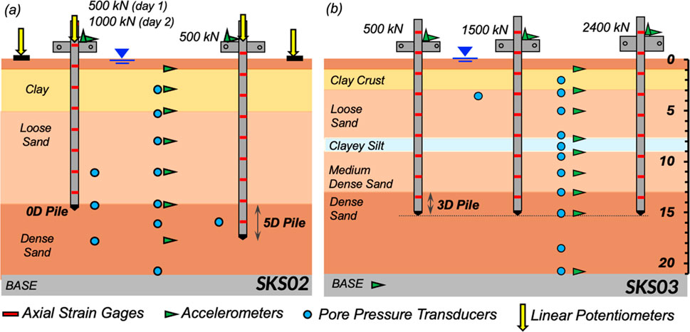
Figure 6. Centrifuge model tests (a) SKS02 and (b) SKS03 including soil layering, instrumentation and instrument locations, and pile properties (embedment depths 0D, 5D, and 3D corresponding to number of pile diameters into the dense sand; and pile head loads defining factors of safety).
The centrifuge model tests were designed to investigate both typical field conditions and extreme scenarios through systematic variation of key parameters. A primary focus was the pile embedment depth into the dense sand layer, which allowed the research team to quantify how end-bearing conditions influenced downdrag load magnitudes and settlement behavior. The piles were also subjected to different levels of static axial load, applied as a lumped mass at the pile head, to assess the role of factor of safety on the pile response. The static factors of safety, defined as the ratio of the ultimate pile capacity to the applied load, spanned from 1.6 to 12.0, the range commonly used in practice. To simulate seismic conditions, the models were subjected to a sequence of scaled earthquake motions which covered a range of intensities, with peak base accelerations varying from 0.02 g to 0.6 g. The sequential application of multiple shaking events allowed the investigation of how prior seismic history influenced the development of downdrag forces, addressing an important aspect often overlooked in design practice. Between shaking events, sufficient time was allowed for complete soil reconsolidation, confirmed through excess pore pressure measurements from the installed instrumentation.
The centrifuge tests employed state-of-the-art instrumentation to capture high-resolution data on the complex coupled response of the soil-pile system (Sinha et al., 2021c, 2023a, Figure 7). Strain gauge bridges installed at multiple elevations inside the piles provided continuous measurements of axial load distribution. To monitor liquefaction behavior, vertical arrays of pore pressure transducers were densely positioned throughout the soil profile, tracking the generation, dissipation, and redistribution of excess pore pressures during and after seismic events. An innovative aspect of the experimental setup was the implementation of non-contact measurement systems for settlement monitoring. This approach employed laser lines projected onto the model surface and high-contrast markers, with high-speed cameras capturing their movements. Specialized software processed these visual data to yield settlement measurements with sub-millimeter precision. This contactless technique represented a significant advancement over traditional methods, as it allowed highly accurate displacement measurements without introducing sensors that could interfere with the model’s dynamic response.
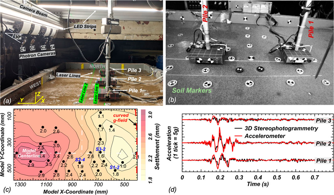
Figure 7. Contactless displacement tracking with high-speed cameras, laser lines, and markers in the centrifuge: (a) view of centrifuge model test SKS03, (b) north section of the model with placed target markers as viewed from camera C2, (c) contours of surface settlement after strong shaking event obtained from settlements measured at soil target markers (shown as dots), and (d) comparison of acceleration in piles obtained from 3D stereophotogrammetry with measurements from accelerometers for shaking event in SKS03.
The results illuminated the mechanics of liquefaction-induced downdrag on piles and allowed important conclusions to be drawn regarding how the various processes interact (Sinha et al., 2022a; 2024). Even modest soil settlements, around 1%–2% of the pile diameter, proved sufficient to generate substantial negative skin friction, with significant downdrag loads developing at excess pore pressure ratios well below full liquefaction (i.e., excess pore pressure ratio of 100%) (Figure 8). During seismic events, the generation of excess pore pressures temporarily alleviates these downdrag forces, but the subsequent reconsolidation phase often sees them return to or exceed their pre-shaking magnitudes. Most of the pile settlement occurs during the shaking phase, when the combined loss of shaft and tip capacity leads to significant displacements. The data also demonstrated that pile embedment depth plays a key role in controlling these settlements: piles extending well into the dense sand layer experienced minimal settlement, provided that the tip is not compromised by the generation of excess pore pressures. The latter was observed due to the redistribution of pore pressures from the loose layers (Sinha et al., 2024). Beyond individual pile behavior, the study emphasized the importance of differential settlement between the pile and surrounding soil, particularly for bridge structures where such differences can compromise functionality. These observations culminate in two essential design considerations: the pile’s response to inertial loading during shaking with reduced resistance, and the evolution of downdrag loads during post-liquefaction reconsolidation. Additionally, the results suggest that separate serviceability criteria should be established for total and differential settlements to ensure structural functionality.
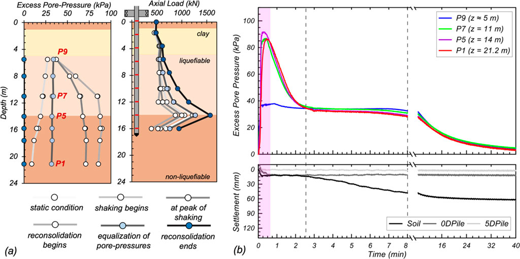
Figure 8. Indicative results from centrifuge model test SKS02: (a) distributions of excess pore pressures and axial loads along 5D pile at different time instants during and after shaking, and (b) time histories of excess pore pressures at pore pressure transducers and settlements of soil and piles.
The experimental data from the centrifuge tests paved the way for the development and validation of an improved load-transfer (neutral plane) numerical modeling procedure for analyzing piles subject to liquefaction-induced downdrag. This was achieved by accounting for changes in the stiffness and capacity of the pile’s shaft friction and tip resistance in liquefiable soils. Sinha et al. (2022b) developed a TzQzLiq analysis method, built upon the OpenSees finite element platform (McKenna et al., 2010), which incorporates interface elements to capture the dependence of pile shaft and tip load transfer on the excess pore pressure ratio in the surrounding soil. The TzLiq and QzLiq interface elements utilize extended versions of conventional t-z and Q-z curves that degrade the pile resistances according to a power law function of excess pore pressure ratio. When validated against centrifuge test results, the TzQzLiq analysis accurately reproduced the recorded time histories of axial load distribution and pile head settlement during both shaking and post-shaking reconsolidation phases. Building upon these insights, Sinha et al. (2023b) developed a displacement-based design procedure for piles in liquefiable soils that, unlike the force-based framework in AASHTO (2020), rationally integrates the key mechanisms governing the combined seismic and liquefaction response of piles. The method uses TzQzLiq analysis to generate pile head settlement versus length design curves for given earthquake motions by systematically varying pile length while keeping other parameters constant. This allows designers to select pile lengths that satisfy project-specific settlement criteria, potentially realizing economic savings compared to traditional approaches that treat liquefaction as an equivalent consolidation problem without considering shaking-induced settlements and excess pore pressure effects on pile resistances.
Enabled by the well-instrumented test series at the CGM, this body of work marked a significant step forward in the profession’s ability to rationally evaluate and design pile foundations to withstand liquefaction-induced downdrag. The high-quality experimental data from the centrifuge tests, obtained using advanced and newly developed instrumentation techniques, provided an unprecedented characterization of the complex soil-pile-interaction mechanisms at play. In addition, the contributions to the development of contactless displacement tracking methods and data processing are poised to enable future work on remaining questions (e.g., pile groups and pile caps, effect of lateral confinement).
4 Research example: large deformation flow problems–runout behavior of waste materials
Mining operations for extracting ore and coal burning for generating electricity produce particulate waste materials that can be harmful to human health and the environment. These materials must be contained in engineered storage facilities that are stable during construction and closure as well as during natural events such as intense rainfall and earthquakes. Large quantities of these waste materials are produced worldwide; the dams containing these materials can reach heights of over 250 m (e.g., Las Tortolas in Chile, Dyncrude in Canada, Pena Negra in Peru). Failures of storage facilities in many countries in the last 30 years have resulted in significant life and economic loss and environmental degradation effects (Santamarina et al., 2019). Failure of a containment structure can trigger flow of the waste material downstream for several kilometers, as was the case in Brumadinho (Brazil), Merriespruit (South Africa), Kingston (United States), and Mount Polley (Canada).
The complex behavior of these waste materials combined with changing or unknown geologic and hydraulic conditions complicates the full understanding of the processes leading to initial failure and subsequent runout. Centrifuge testing has emerged as a useful tool for isolating the mechanisms that lead to triggering of failures, such as a rising water table (e.g., Ng et al., 2023) and generation of excess pore pressures in contractive materials (i.e., static liquefaction) (Madabhushi et al., 2023). Such research can isolate processes that govern failure and flow of material to inform the development of constitutive models for material behavior at both small and large deformations. In addition, these centrifuge experiments can be used to calibrate and validate numerical models to subsequently investigate a broader set of conditions numerically (as shown in Figure 2).
Equipment to model large deformation processes in geomaterials was designed, built, and commissioned at the UC Davis CGM between 2018 and 2020. The new equipment enables modeling the runout behavior of waste materials as confinement is rapidly lost at applied accelerations of up to 60 g. The equipment consists of a container in which the waste material is placed, two doors that can be rapidly opened to release the material using a pair of hydraulic actuators, and an interchangeable runout basin. Figure 9a shows a schematic of the main components of the equipment, while Figure 9b details mechanisms that keep the doors closed during centrifuge spin up and then rapidly open the doors to release the material. The material response is monitored using pore pressure transducers and electrical permittivity sensors mounted on the inner side walls of the container, while the evolution of the runout process is measured using high-speed and depth-sensing cameras. This system also allows mounting sensors in the runout basin to elucidate processes such as pore pressure generation and material entrainment or deposition. Additionally, cone penetration tests (CPTs) can be performed in flight to characterize the initial properties of the waste material before the doors are opened. Detailed information of this equipment and sample results are provided in Madabhushi et al. (2022).
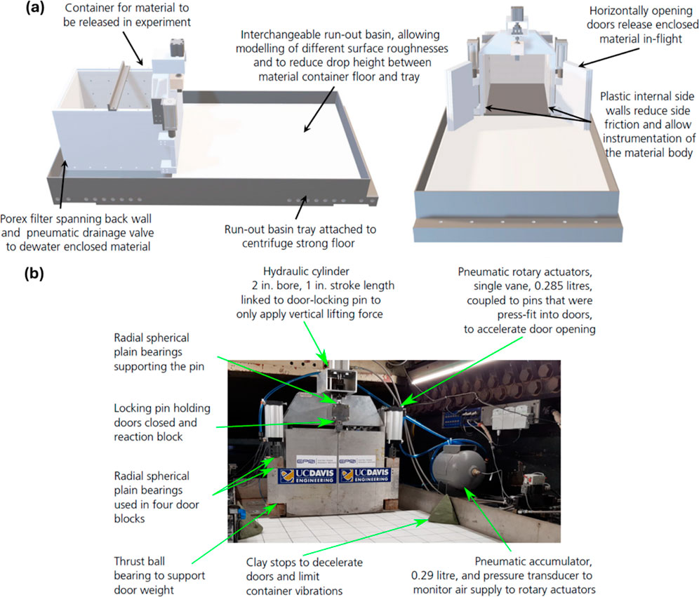
Figure 9. (a) Schematic and (b) photograph of the container for modeling runout of waste materials for the 9-m centrifuge at the UC Davis CGM.
Given the significant challenges in obtaining data from a containment facility failure in the field and the uncertainty in the initial geological and hydraulic settings and material properties, centrifuge testing can offer unique datasets to better understand material behavior at high deformations and to guide the continued development of numerical tools to predict systems level behavior. A series of experiments were performed at 60 g to investigate how the susceptibility to flow failure and severity of runout deformations depend on the initial density of waste material, the location of the water table within the material deposit, and the type of waste material (Madabhushi et al., 2023). The results showed that initially loose, saturated deposits, characterized by high void ratios and low CPT penetration resistances, are prone to static liquefaction, leading to rapid failures and large runout distances upon loss of confinement. Figure 10 shows a series of high-speed video frames showing the rapid failure characterized by intense material deformation over a period of about one second. In contrast, denser materials failed in a slope instability mode and exhibited runout distances approximately equal to their initial height. Figure 11 shows data from the depth-sensing cameras on the test on the denser deposit, clearly showing the evolution of the runout process over tens of minutes. These results are being used to help better define the conditions that can lead to failures with large runout distances and to develop procedures for field evaluations based on CPT data.
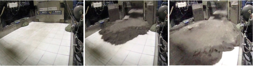
Figure 10. Sequence of failure of a saturated, loose deposit of coal ash tested at 60 g. The images were taken during a time period of about 1 s.
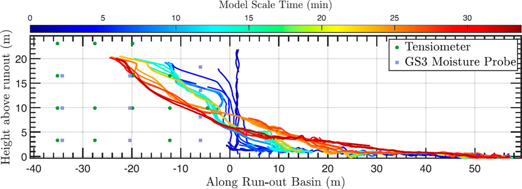
Figure 11. Evolution of runout of a deposit of saturated, dense coal ash at 60 g.
These waste runout events share characteristics with other processes, such as long runout landslides and debris flows due to precipitation or wildfires (e.g., Kean et al., 2019). The capabilities built at the UC Davis CGM expand on those developed in previous investigations (e.g., Bowman et al., 2010) by enabling modeling a wider range of initial conditions of the material, including the height of the deposit, location of the water table, and density of the material. Future investigations can expand on this work to explore the material response while it runs across the basin by including pore pressure transducers and net pressure sensors. Additionally, the equipment can be modified in the future to consider different initial failure conditions, such as an embankment with a rising water table or a sudden increase in pore pressure within the soil.
5 Research example: upscaling of MICP technology
Biogeotechnics, especially biomediated and bioinspired geotechnical engineering, focuses on improving geotechnical systems through natural pathways. This emerging domain has advanced significantly over the past two decades, establishing itself as one of the most rapidly evolving fields within geotechnics. As the field advances, there is an increasing demand to investigate new engineering techniques at various scales to evaluate their practicality and effectiveness for real-world applications. For example, microbially induced calcium carbonate precipitation (MICP) is a promising novel technology that improves the behavior of sands by enhancing particle-particle contacts, creating surface coatings on particles, and modifying particle angularity (DeJong et al., 2022). Biomediation with MICP depends on calcium carbonate precipitation to create a cemented soil that enhances resistance to liquefaction. While particle- and lab-scale studies have shown significant improvements in reducing liquefaction triggering and its consequences, the transition to practical field applications requires a deeper understanding of system-level response. To address this gap, the synergistic use of the 1-m and 9-m centrifuges at the UC Davis CGM has provided unique opportunities to investigate MICP technology at progressively larger scales, addressing critical challenges in upscaling and implementation. The centrifuges have enabled researchers to examine key factors such as treatment formulation, dynamic response, soil stratigraphy, and soil-structure interaction under realistic stress conditions, providing essential guidance for future field application of these technologies. Six complementary centrifuge studies investigating MICP biomediation described herein highlight the collective contribution of centrifuge technologies toward addressing challenges in practical design and implementation of this emerging technology (Figure 12).
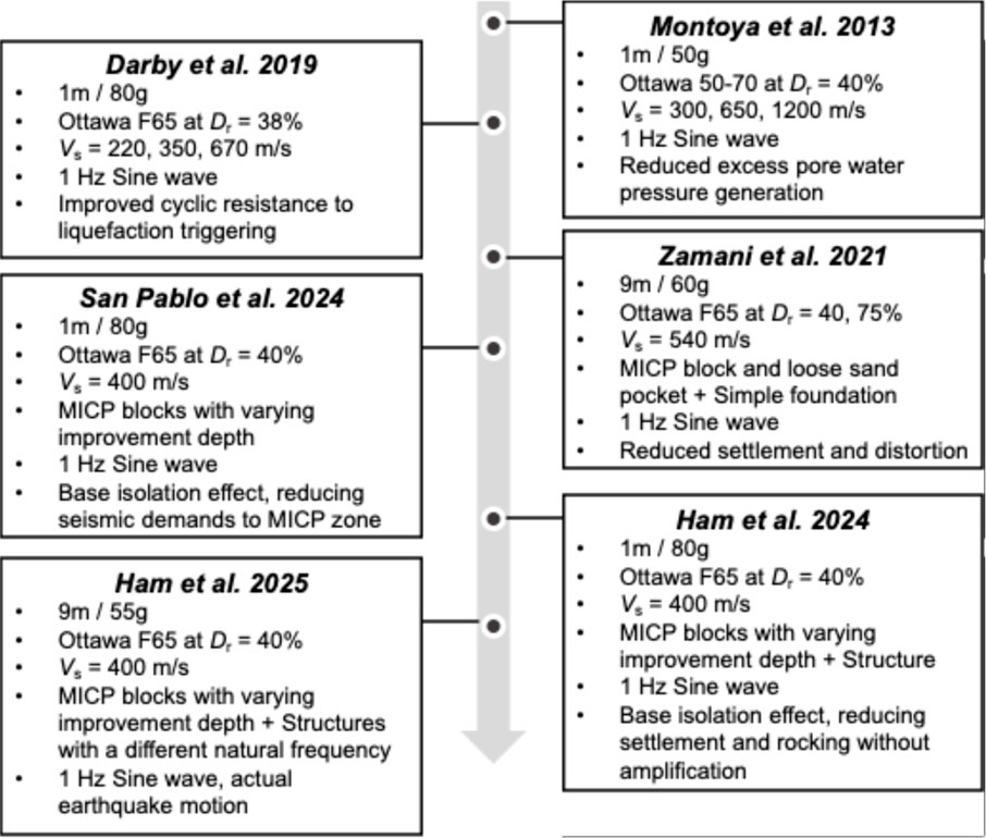
Figure 12. Synergistic use of 1-m and 9-m centrifuges to advance MICP ground improvement technology towards the field scale.
The investigation into the use of MICP treatment to mitigate liquefaction triggering and subsequent consequences started with 1-m centrifuge tests. Studies by Montoya et al. (2013) and Darby et al. (2019) used the 1-m centrifuge to systematically investigate the fundamental mechanisms and behavior of MICP treated soils under controlled loading conditions. Simple, small-scale models allowed for efficient testing, making it suitable for exploring fundamental principles, improving model construction protocols, and establishing reliable in-flight characterization methods, such as cone penetration testing and shear wave velocity measurements. These studies marked the first-ever measurements of critical mechanisms, demonstrating that the MICP treatment significantly reduced pore water pressure generation and enhanced cyclic resistance under dynamic loading. Additionally, the degradation of MICP treated soil was analyzed using bender elements, providing valuable insights into how cyclic loading impacts MICP bonding and the effectiveness of MICP treatment after degradation. These initial studies were necessary for building scientific knowledge and guiding the development of larger-scale experiments and practical applications.
Building on insights from the 1-m centrifuge tests, Zamani et al. (2021) upscaled to the 9-m centrifuge to explore more complex geotechnical scenarios including stratified soil profiles and finite treatment zones. The 1-m tests, while effective in understanding fundamental behaviors, had limitations due to the small size of the model container and limited resources available onboard the centrifuge. These limitations included treating the entire container with MICP—a condition not representative of future real-world field applications—and limitations in measurement capabilities, particularly in capturing higher shear strains. The 9-m centrifuge, having enhanced capabilities and a larger physical model size, enabled examining the effect of MICP on finite liquefiable pockets in a stratified soil profile and assessing the performance of simple foundation structures on soils with varying relative densities and MICP treatment. Two MICP treated blocks representing finite treatment zones at different depths were implemented to evaluate impact on soil and foundation performance. A new model preparation method was introduced to enable this advanced testing that involved placing precast MICP treated blocks into the centrifuge model (Ham et al., 2024b). The MICP blocks were created in PVC molds and carefully lifted, inverted, and positioned onto the soil model at the target depth using a vacuum lifting system (Figure 13a) before being buried. Instrumentation, including accelerometers, pore pressure transducers, bender elements, and displacement sensors, monitored the responses of the soil and foundations during and after dynamic loading. These experiments provided essential insights into the system-level performance of MICP treatments, revealing their potential to enhance foundation performance by reducing settlement and rotation significantly. A notable advantage of the large-scale test was the ability to facilitate direct comparisons across different treatment strategies within a single experimental setup, ensuring consistency in soil preparation and applied shaking conditions.
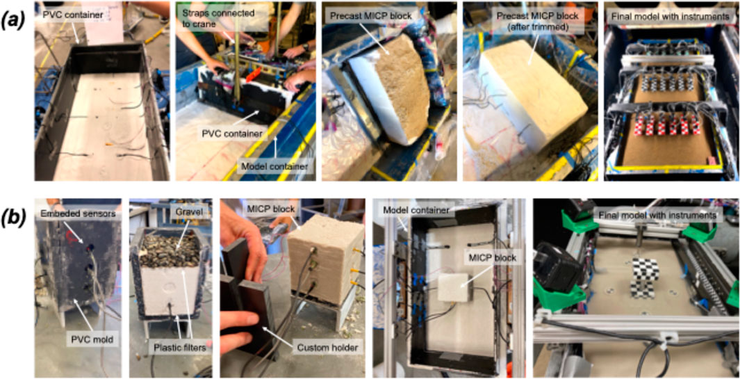
Figure 13. Model preparation process with discrete MICP-treated blocks: (a) 9-m centrifuge model and (b) 1-m centrifuge model.
While the 9-m centrifuge test provided valuable insights into a complex geotechnical scenario, the complexity of combining varying soil stratigraphy, finite MICP treated zones, and soil structure interaction in one system highlighted a need for additional focused experiments to isolate specific mechanisms. San Pablo et al. (2024) returned to using 1-m centrifuge tests to focus on the fundamental influence of discrete MICP treatment depth in loose soils on liquefaction resistance, especially surface settlement, ground surface acceleration, and MICP degradation. Single discrete MICP treated blocks were created to represent realistic localized treatment zones for each of several soil models. The preparation methodology for the 1-m centrifuge models was similar to that of the 9-m test outlined above (Ham et al., 2024b). The simplified tests explored varying the depth of MICP treatment within a liquefiable soil profile, ranging from untreated to fully and partially treated layers (Figure 13b). The results revealed a base isolation effect from the untreated loose sand below the MICP treated blocks which mitigated accelerations transmitted to the model surface. The isolation tended to balance settlement reduction and reduced dynamic load effects compared to the untreated base case. Fully treated soil layers where MICP treatment extended the full depth of the soil achieved the most significant decrease in settlement but transferred higher accelerations to the surface due to increased stiffness. Partially treated layers demonstrated a compromise, with reduced surface accelerations at the cost of slightly increased settlement.
Most recently, researchers have been extending the work of San Pablo et al. (2024) by adding aspects of soil-structure interaction with discrete MICP treated zones using both the 1-m and 9-m centrifuges. Simple tests using single structures on the 1-m centrifuge focused on understanding the balance between increased structural demands from shaking energy transferred through the MICP treated zone with reduced settlement and tilting due to soil stabilization. Ham et al. (2024a) introduced a high-speed camera system on the 1-m centrifuge to monitor structural behavior and soil settlement, addressing the challenge of wire interference in small-scale tests, especially at higher g-levels. A checkerboard-marked structure and soil markers were placed to enable precise tracking of movements using high-speed cameras, as shown in Figure 14a. The results demonstrated that partial improvement of a liquefiable layer with MICP treatment can effectively minimize structural settlement and rocking without amplifying accelerations with the base isolation effect. However, the limitations of using a single structure and input motion highlighted the need for further research to generalize these findings. A subsequent 9-m centrifuge test was performed to explore soil-structure interaction under more realistic conditions. This test included structures with varying natural frequencies to represent a broader range of dynamic behavior. Like the 1-m test, high-speed cameras and 3D photogrammetry were used to monitor structural responses (Figure 14b) (Sinha et al., 2021d). The larger scale of the 9-m centrifuge allowed for a more comprehensive investigation, highlighting the trade-offs between minimizing structural settlement and reducing dynamic accelerations through MICP treatment (Ham et al., 2025).
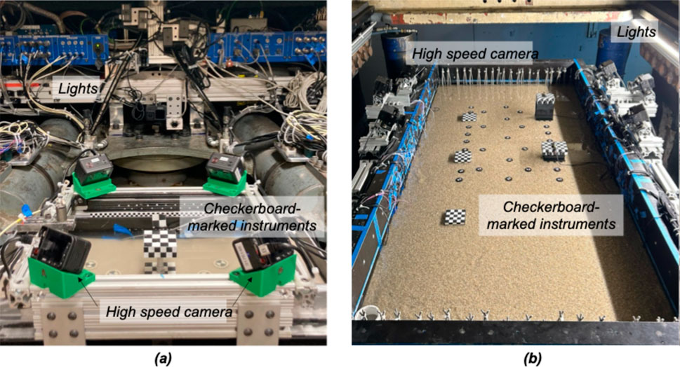
Figure 14. Experimental setup with high-speed cameras, structure markers, and soil markers: (a) component level model for testing on the 1-m radius centrifuge, and (b) system level model for testing on the 9-m radius centrifuge.
The synergistic use of the 1-m and 9-m centrifuges supported the progression of biogeotechnical engineering from relatively simple tests to increasingly complex larger-scale system investigations. The 1-m centrifuge facilitated efficient parametric studies and the isolation of critical mechanisms, while the 9-m centrifuge enabled realistic modeling of complex geotechnical scenarios, including varying soil stratigraphy, discrete MICP treated zones, and diverse structural configurations. These studies collectively demonstrate the potential of MICP in balancing structural stability with dynamic response, paving the way for the practical application of this innovative technology in real-world scenarios. Centrifuge testing will continue to bridge the gap between laboratory studies and practical design, advancing MICP treatment to transform ground improvement practices and support resilient geotechnical solutions.
6 Future directions and research opportunities
Over the past few decades, hypergravity modeling has transformed the field of geotechnical engineering by enabling researchers to examine system-level performance and the respective underlying mechanisms within a controlled laboratory environment where test conditions can be specified and controlled while remaining realistic. Centrifuge modeling has advanced from a niche research tool to one of the preferred approaches for prototyping new technologies at the system scale, advancing engineering analysis and design methods, and validating advanced computational models (e.g., Travasarou, 2024). This transformation has been enabled by rigorous implementation of research fundamentals and principles (e.g., Schofield, 1981; Kutter, 1995; Garnier et al., 2007), collaboration and sharing of best practices between centrifuge facilities (e.g., the International Journal and the International Conference series of Physical Modelling in Geotechnics, IJPMG and ICPMG), researcher and staff exchanges, coordinated research efforts (e.g., Verification of Liquefaction Analysis by Centrifuge Studies, Arulanandan and Scott, 1993; Liquefaction Experiments and Analysis Project; Manzari et al., 2018), and collective brainstorming and envisioning of the future of hypergravity modeling (e.g., Kutter et al., 2021). The combined experience and knowledge base, combined with the innate attributes of hypergravity scaled physical modeling, position this research approach to extend efficiently and effectively into new science and engineering research topics where existing approaches are deficient.
The role of hypergravity modeling in geotechnical engineering is likely to continue to increase given that the understanding and performance prediction of numerous challenging soils remain (e.g., silts, tailings, volcanics, glauconite, carbonates), geotechnical infrastructure is becoming increasingly larger, more complex, and multi-functional (e.g., Mitchell and Kopmann, 2013), and the impacts of anthropogenic-induced loading conditions are just starting to be considered (Bridges, 2024). This is in addition to numerous seismic-related issues that have yet to be sufficiently resolved (e.g., basin effects), the remaining opportunities in the young field of biogeotechnics, and that capabilities for addressing other issues with hypergravity modeling have yet to be developed (e.g., creation of models with fine depositional variability). Consensus of some of major remaining and upcoming challenges have been detailed in three editions of the NHERI Science Plan (Boulanger et al., 2017; Edge et al., 2020; Robertson et al., 2023), which highlights challenges related to earthquakes, windstorms, and associated hazards, and the NHERI Decadal Vision Plan (Schneider and Kosters, 2024), which highlights impacts of climate change on natural hazards research and use-inspired and translational research. Collectively, the breadth and complexity of challenges that remain in geotechnical engineering is both significant and well-suited to be addressed by hypergravity modeling.
New applications at the CGM are rapidly being developed to enable critical climate related research, where problems like thawing permafrost have major impacts on civil infrastructure and a lack of fundamental knowledge affects the ability to predict and thus respond to changes in the Artic and Antarctic. The CGM is seeing considerable investment developing new environmental control capabilities to study these processes. For example, Gardner et al. (2024) is piloting modeling the effects of permafrost thawing and its effect on foundation performance, and the National Science Foundation has made recent NSF awards to Khosravi (CMMI 2400391) and Khosravi (CMMI 2228271) to support the development of a new container for the 9-m centrifuge and supporting infrastructure (e.g., onboard chillers) to actively control cryosphere conditions.
In addition, significant growth opportunities exist more broadly outside the general domain of geotechnical engineering. The role of hypergravity modeling across engineering and science was explored through a recent international workshop. Kutter et al. (2021) assembled a diverse group of scientists and engineers to identify significant opportunities for collaboration between centrifuge experts and researchers in fields where hypergravity techniques are not yet generally accepted or used. Gravity affects many physical quantities including weight, buoyancy, convection, pressure, stress, pressure gradients, and potential energy. These in turn affect secondary quantities such as flow rate, frictional resistance, stability, advection, and consolidation. These secondary quantities play roles in many processes such as the large-scale behavior and stability of granular materials, tectonic structures, combustion and fire, thermal oceanic circulation, and nuclear waste disposal. The ability to adjust gravity can also be a valuable tool by which experiments illuminate microscale phenomena such as crystallization, the stability of liquid bridges between particles, and interactions between gravity forces and interparticle cohesive forces. Opportunities for new hypergravity research thus span a wide range of engineering and scientific disciplines, including many subdisciplines of civil and mechanical engineering, materials science, geosciences, glaciology, artic sciences, oceanography, combustion sciences, and plant physiology.
7 Concluding remarks
The Natural Hazards Engineering Research Infrastructure (NHERI) facility at the University of California at Davis is equipped with 9-m and 1-m radius geotechnical centrifuges that provide unique, world-class facilities for scaled modeling of systems and hypergravity environments. This national, open access research facility allows the scientific and engineering communities to realize major advances in the ability to understand, predict, and improve the performance of civil infrastructure and natural systems. Four research projects were used to illustrate the facility’s capabilities and the complementary roles of the 9-m and 1-m centrifuges. The examples included renewable energy systems, pile performance in liquefiable soils, large deformation flow problems, and advancement of biogeotechnical technologies, reflecting the increasing diversity of topics being researched using the CGM facility. A broader discussion of the envisioned future research directions and opportunities using hypergravity modeling was then presented, concluding that there remain significant opportunities within geotechnical engineering, particularly related to natural and anthropogenic-induced loadings, and that the opportunities more broadly in engineering and science are just beginning to be realized and explored.
Data availability statement
The original contributions presented in the study are included in the article/supplementary material, further inquiries can be directed to the corresponding author.
Author contributions
JD: Writing – original draft, Writing – review and editing. DW: Writing – original draft, Writing – review and editing. AM: Writing – original draft, Writing – review and editing. KZ: Writing – original draft, Writing – review and editing. S-MH: Writing – original draft, Writing – review and editing. RB: Writing – review and editing.
Funding
The author(s) declare that financial support was received for the research and/or publication of this article. The National Science Foundation (NSF) has supported the development and operation of the geotechnical centrifuge facilities at UC Davis through the Network for Earthquake Engineering Simulation (NEES) program, award numbers CMS-0086566, CMMI-0402490, and CMMI-0927178, and the Natural Hazards Engineering Research Infrastructure (NHERI) program, award number CMMI 1520581 and 2037883. Additional support for facility development has been provided by Obayashi Corporation, Caltrans, and the University of California at Davis. The four research examples presented herein were supported by the US National Science Foundation (CMMI-1936939 and EEC-1449501), Caltrans (Agreement 65A0688), and the Electric Power Research Institute. Any opinions, findings and conclusions or recommendations expressed in this material are those of the author(s) and do not necessarily reflect those of the above organizations.
Acknowledgments
Contributions to facility developments were provided by past CGM Directors Bruce Kutter, Jim Cheney, and I. M. Idriss as well as all former and current CGM staff and graduate students.
Conflict of interest
The authors declare that the contents of this paper were prepared in the absence of any commercial or financial relationships that could be construed as a potential conflict of interest.
Generative AI statement
The author(s) declare that no Generative AI was used in the creation of this manuscript.
Publisher’s note
All claims expressed in this article are solely those of the authors and do not necessarily represent those of their affiliated organizations, or those of the publisher, the editors and the reviewers. Any product that may be evaluated in this article, or claim that may be made by its manufacturer, is not guaranteed or endorsed by the publisher.
References
Arulanandan, K., and Scott, R. F. (1993). Project VELACS—control test results. ASCE J. Geotechnical Eng. 119 (8), 1276–1292. doi:10.1061/(ASCE)0733-9410(1993)119:8(1276)
Aubeny, C. (2017). Geomechanics of marine anchors. 1st ed. Boca Raton, FL: CRC Press. doi:10.4324/9781351237376
Boulanger, R. W., and Brandenberg, S. J. (2004). “Neutral plane solution for liquefaction-induced down-drag on vertical piles,” in Geotechnical engineering for transportation projects (Reston, VA: ASCE), 470–478. doi:10.1061/40744(154)32
Boulanger, R. W., Bray, J. D., Deierlein, G. G., Irish, J. L., Lizundia, B., Masters, F. J., et al. (2017). Natural hazards engineering research infrastructure, 5-year science plan, multi-hazard research to make a more resilient world. First Edition. DesignSafe-CI. Available online at: https://www.designsafe-ci.org/media/filer_public/20/6f/206f5d4a-5f7d-4ab6-b837-7c5f89c7b251/varwwwdesignsafe-ciorgmediacms_page_media595nheri_science_plan_july_2017.pdf.
Boulanger, R. W., Wilson, D. W., Kutter, B. L., DeJong, J. T., and Bronner, C. E. (2020). NHERI centrifuge facility: large-scale centrifuge modeling in geotechnical research. Front. Built Environ. 6. doi:10.3389/fbuil.2020.00121
Bowman, E. T., Laue, J., Imre, B., and Springman, S. M. (2010). Experimental modelling of debris flow behaviour using a geotechnical centrifuge. Can. Geotechnical J. 47 (7), 742–762. doi:10.1139/T09-141
Bradshaw, A. S., Giammp, J. R., Gerkus, H., Jalilvand, S., Fanning, J., Nanda, S., et al. (2016). Scaling considerations for 1-g model horizontal plate anchor tests in sand. ASTM Geotechnical Test. J. 39 (6), 20160042. doi:10.1520/gtj20160042
Bray, J. D., Frost, J. D., Rathje, E. M., and Garcia, F. E. (2019). Recent advances in geotechnical post-earthquake reconnaissance. Front. Built Environ. 5, 5–2019. doi:10.3389/fbuil.2019.00005
Bridges, C. A. (2024). “Climate change inpacts on geotechnical infrastructure,” in XVIII European conference on soil mechanics and geotechnical engineering, Lisbon, Portugal, 2838–2841. doi:10.1201/9781003431749-553
Carey, T. J., Chiaradonna, A., Love, N. C., Wilson, D. W., Ziotopoulou, K., Martinez, A., et al. (2022). Effect of soil gradation on embankment response during liquefaction: a centrifuge testing program. Soil Dyn. Earthq. Eng. 157, 107221. doi:10.1016/j.soildyn.2022.107221
Carey, T. J., Gavras, A. G., Kutter, B. L., Haigh, S. K., Madabhushi, S. P. G., Okamura, M., et al. (2018). A new shared miniature cone penetrometer for centrifuge testing. London, United Kingdom. 293, 298. doi:10.1201/9780429438660-38
Chen, J., and Martinez, A. (2025). A centrifuge modelling setup for dewatering, rewetting, and characterising soil deposits. Inter. J. Phys. Modell. Geotech. 25, 86, 101. doi:10.1680/jphmg.24.00027
Coughlan, K. (2024). Mooring systems for floating offshore wind: mooring design, biocolonisation, and shared anchors. Amherst, MA: University of Massachusetts. PhD thesis.
Darby, K. M., Hernandez, G. L., DeJong, J. T., Boulanger, R. W., Gomez, M. G., and Wilson, D. W. (2019). Centrifuge model testing of liquefaction mitigation via microbially induced calcite precipitation. ASCE J. Geotechnical Geoenvironmental Eng. 145 (10), 04019084. doi:10.1061/(ASCE)GT.1943-5606.0002122
Davis, M. (2023). Loads analysis of fixed-bottom and floating offshore wind structures. MS thesis. Amherst (MA): University of Massachusetts.
DeJong, J. T., Gomez, M. G., San Pablo, A. C. M., Graddy, C. M. R., Nelson, D. C., Lee, M., et al. (2022). “State of the Art: MICP soil improvement and its application to liquefaction hazard mitigation,” in Proc. of the 20th ICSMGE-state of the art and invited lectures. Sydney, Australia.
Edge, B., Ramirez, J., Peek, L., Bobet, A., Holmes, W., Robertson, I., et al. (2020). Natural hazards engineering research infrastructure, 5-year science plan, multi-hazard research to make a more resilient world, Second Edition. DesignSafe-CI. doi:10.17603/ds2-4s85-mc54
Exton, M., Harry, S., Kutter, B. L., Mason, H. B., and Yeh, H. (2019). Simulating tsunami inundation and soil response in a large centrifuge. Sci. Rep. 9, 11138. doi:10.1038/s41598-019-47512-x
Fellenius, B. H., and Siegel, T. C. (2008). Pile drag load and downdrag in a liquefaction event. J. Geotech. Geoenviron. Eng. 134 (9), 1412–1416. doi:10.1061/(ASCE)1090-0241(2008)134:9(1412)
Fontana, C. M., Hallowell, S. T., Arwade, S. R., DeGroot, D. J., Landon, M. E., Aubeny, C. P., et al. (2018). Multiline anchor force dynamics in floating offshore wind turbines. Wind Energy 21 (11), 1177–1190. doi:10.1002/we.2222
Gardner, M. H., Khan, H., Buttery, S., Ham, S.-M., DeJong, J. T., and Wilson, D. W. (2024). Hypergravity testing of thawing rates in permafrost. American geophysical union conference, San Francisco, CA, December 12, 2024. Available online at: https://agu.confex.com/agu/agu24/meetingapp.cgi/Paper/1559696.
Garnier, J., Gaudin, C., Springman, S. M., Culligan, P. J., Goodings, D., Konig, D., et al. (2007). Catalogue of scaling laws and similitude questions in geotechnical centrifuge modelling. Int. J. Phys. Model. Geotech. 7 (3), 01–23. doi:10.1680/ijpmg.2007.070301
Hall, C. A., Hernandez, G., Darby, K. M., van Paassen, L., Kavazanjian, E., DeJong, J. T., et al. (2018). “Centrifuge model testing of liquefaction mitigation via denitrification-induced desaturation,” in Proc., geotechnical earthquake Engineering and soil dynamics V, geotechnical special publication 290. Editors S. J. Brandenberg, and M. T. Manzari (ASCE), 127–137.
Ham, S., San Pablo, A. C. M., Caisapanta, J. L., and DeJong, J. T. (2024a).“Centrifuge modeling of soil-structure interaction with MICP improved soil,” Proc., Geo-Congress 2024, Vancouver, BC, February 25-28, 2024, 87–95. doi:10.1061/9780784485330.010
Ham, S., San Pablo, A. C. M., Wilson, D. W., and DeJong, J. T. (2024b). “Development of model preparation procedure for MICP-treated sand in centrifuge tests,” in Proc., 5th European Conference on physical Modelling in Geotechnics, Delft, Netherlands, October 2-4, 2-24.
Ham, S. M., Caisapanta, J. L., San Pablo, A. C. M., and DeJong, J. T. (2025). MICP ground improvement design to support structures founded on liquefiable soils. Biogeotechnics, in review.
Hannigan, P. J., Rausche, F., Likins, G. E., Robinson, B. R., and Becker, M. L. (2016). Design and construction of driven pile foundations. FHWA-NHI-16-009. Woodbury, MN: Federal Highway Administration.
Huang, L., Coughlan, K., Martinez, A., Wilson, D., Aubeny, C., Arwade, S., et al. (2025a). Centrifuge modelling of shared ring anchors for floating wind turbines subjected to cyclic loading in clay. Proc. 5th Int. Sym. Front. Off. Geotech, , Nantes, France, June 9-13, 2025. 6.
Huang, L., Martinez, A., Aubeny, C., Awade, S., DeGroot, D., and Beemer, B. (2025b). Centrifuge modelling of the monotonic capacity of offshore ring anchors in clay. Geotech. Frontiers. 290–299. doi:10.1061/9780784486009.030
Huang, L., Martinez, A., Aubeny, C., DeGroot, D., Arwade, S., and Beemer, R. (2024). Centrifuge modeling of the monotonic capacity of offshore ring anchors in sand. Deep Found. Inst. J. 18 (1). doi:10.37308/dfijnl.20230915.297
Kean, J. W., Staley, D. M., Lancaster, J. T., Rengers, F. K., Swanson, B. J., Coe, J. A., et al. (2019). Inundation, flow dynamics, and damage in the 9 January 2018 Montecito debris-flow event, California, USA: opportunities and challenges for post-wildfire risk assessment. Geosphere 15 (4), 1140–1163. doi:10.1130/GES02048.1
Khosravi, M., DeJong, J. T., Boulanger, R. W., Khosravi, A., Hajialilue-Bonab, M., Sinha, S. K., et al. (2022). Centrifuge tests of cone-penetration test of layered soil. ASCE J. Geotechnical Geoenvironmental Eng. 148 (4), 04022002. doi:10.1061/(ASCE)GT.1943-5606.0002716
Kim, Y. A., Burrall, M., Jeon, M. K., DeJong, J. T., Martinez, A., and Kwon, T. H. (2024). Pullout behavior of tree root-inspired anchors: development of root architecture models and centrifuge tests. Acta Geotech. 19 (3), 1211–1229. doi:10.1007/s11440-023-02077-y
Komusanac, I., Brindley, G., Fraile, D., and Lizet, R. (2022). Wind energy in europe: 2021 statistics and the outlook for 2022–2026. Brussels, Belgium: WindEurope. Available online at: https://windeurope.org/intelligence-platform/product/wind-energy-in-europe-2021-statistics-and-the-outlook-for-2022-2026/.
Kutter, B. L. (1995). Recent advances in centrifuge modeling of seismic shaking. International conferences on recent advances in geotechnical earthquake engineering and soil dynamics, St. Louis, Missouri, April 2-67, 1995, 2.
Kutter, B. L., and Balakrishnan, A. (1998). Dynamic model test data from electronics to knowledge. International Conference Centrifuge 98, 931–943. Available online at: https://www.issmge.org/uploads/publications/53/115/P00121.pdf
Kutter, B. L., Fragaszy, R. J., Gaudin, C., Carey, T. J., Chen, Y., De, A., et al. (2021). Frontiers for hypergravity experiments and model tests. UC Davis CGM Rep. UCD/CGM-21/02. Available online at: https://ucdavis.box.com/s/fqs8srl0v0091p417s4c39jyt9lij34c (Accessed December 1, 2024).
Kutter, B. L., and Wilson, D. W. (2006). Physical modelling of dynamic behavior of soil-foundation-superstructure systems. Int. J. Phys. Model. Goetechnics 6 (1), 01–12. doi:10.1680/ijpmg.2006.060101
LeBlanc, C., Houlsby, G. T., and Byrne, B. W. (2010). Response of stiff piles in sand to long-term cyclic lateral loading. Géotechnique 60 (2), 79–90. doi:10.1680/geot.7.00196
Lee, J., Khan, M., Bello, L., and Aubeny, C. (2020). “Cost analysis of multiline ring anchor system for offshore wind farm,” in 45th Annual Conf. on Deep Foundations, October 13-16, 2020.
Litton, R. W., Stringer, M. E., Clukey, E. C., Chen, J.-Y., Kutter, B. L., Wilson, D. W., et al. (2014). Centrifuge study of offshore platform response to earthquake excitations. Houston, Texas: Offshore Technology Conference. doi:10.4043/25206-MSOffshore Technol. Conf.
Madabhushi, S. S. C., Follett, S. B., O'Hara, K. B., Wilson, D. W., Kutter, B. L., and Martinez, A. (2023). Centrifuge modeling of the run-out behavior of fly ash deposits subjected to a loss of confinement. Can. Geotech. J. 61 (3), 375–399. doi:10.1139/cgj-2022-0585
Madabhushi, S. S. C., Martinez, A., Wilson, D. W., and Kutter, B. L. (2022). Design and instrumentation of a novel centrifuge container for fly ash run-out experiments. Int. J. Phys. Mod. Geotech. 23 (3), 129–149. doi:10.1680/jphmg.21.00044
Manzari, M. T., El Ghoraiby, M., Kutter, B. L., Zeghal, M., Abdoun, T., Arduino, P., et al. (2018). Liquefaction experiment and analysis projects (LEAP): summary of observations from the planning phase. Soil Dyn. Earthq. Eng. 113, 714–743. doi:10.1016/j.soildyn.2017.05.015
Martinez, A., and O'Hara, K. B. (2021). Skin friction directionality in monotonically- and cyclically-loaded bio-inspired piles in sand. Deep Found. Inst. J. 15 (1). doi:10.37308/DFIJnl.20200831.222
Mason, H. B., Kutter, B. L., Bray, J. D., Wilson, D. W., and Choy, B. Y. (2010). “Earthquake motion selection and calibration for use in a geotechnical centrifuge,” Proc. Int. Conf. Physical Modelling in Goetechnics. Zürich, June 2010, 361–366. doi:10.1201/b10554-56
McKenna, F., Scott, M. H., and Fenves, G. L. (2010). Nonlinear finite element analysis software architecture using object composition. J. Comput. Civ. Eng. 24 (1), 95–107. doi:10.1061/(asce)cp.1943-5487.0000002
Mitchell, J. K., and Kopmann, J. (2013). The future of geotechnical engineering. Blacksburg, VI, United States: Virginia tech center for geotechnical research and practice, Report #70.
Montoya, B. M., DeJong, J. T., and Boulanger, R. W. (2013). Dynamic response of liquefiable sand improved by microbial-induced calcite precipitation. Géotechnique 63 (4), 302–312. doi:10.1680/geot.SIP13.P.019
Muhunthan, B., Vijayathasan, N. V., and Abbasi, B. (2017). Liquefaction induced downdrag on drilled shafts. WA-RD 865.1. Pullman, WA: Washington State DOT.
Ng, C. W. W., Crous, P. A., and Jacobsz, S. W. (2023). Centrifuge and numerical modeling of liquefied flow and nonliquefied slide failures of tailings dams. J. Geotechnical Geoenvironmental Eng. 149 (9). doi:10.1061/jggefk.gteng-10800
O'Hara, K. B., and Martinez, A. (2022). Load transfer directionality of snakeskin-inspired piles during installation and pullout in sands. J. Geotech. Geoenv. Eng. 148 (12). doi:10.1061/(asce)gt.1943-5606.0002929
O'Hara, K. B., and Martinez, A. (2024). Cyclic axial response and stability of snakeskin-inspired piles in sand. Acta Geotech. 19 (3), 1139–1158. doi:10.1007/s11440-023-02007-y
Price, A. B., Boulanger, R. W., and DeJong, J. D. (2019). Centrifuge modeling of variable-rate cone penetration in low-plasticity silts. ASCE J. Geotechnical Geoenvironmental Eng. 145 (11), 04019098. doi:10.1061/(ASCE)GT.1943-5606.0002145
Robertson, I., Bobet, A., Edge, B., Holmes, W., Johnson, D., LaChance, M., et al. (2023). Natural hazards engineering research infrastructure, science plan, multi-hazard research to make a more resilient world, Third Edition. DesignSafe-CI. doi:10.17603/ds2-abbs-0966
Rollins, K. M., and Strand, S. R. (2007). Liquefaction mitigation using vertical composite drains: full-scale testing for pile applications. Washington, DC: Transportation Research Board.
San Pablo, A. C. M., DeJong, J. T., and Carey, T. J. (2024). Influence of biocementation treatment extent on dynamic system performance: a centrifuge liquefaction study. Soil Dyn. Earthq. Eng. 183, 108792. doi:10.1016/j.soildyn.2024.108792
Santamarina, J. C., Torres-Cruz, L. A., and Bachus, B. S. (2019). Why coal ash and tailings dam disasters occur. Science 364 (6440), 526–528. doi:10.1126/science.aax1927
Schneider, N., and Kosters, J. (2024). “U.S. National science foundation natural hazards engineering research infrastructure (NHERI) decadal visioning study 2026–2035,” in U.S. National science foundation natural hazards engineering research infrastructure (NHERI) decadal visioning study 2026–2035. DesignSafe-CI. doi:10.17603/ds2-afza-m544
Schofield, A. N. (1981). Cambridge geotechnical centrifuge operations. Geotechnique 25 (4), 743–761.
Sinha, S. K., Kutter, B. L., Wilson, D. W., Carey, T. J., and Ziotopoulou, K. (2021c). Use of Photron cameras and TEMA software to measure 3D displacements in centrifuge tests. Report No. UCD/CGM-21/01. Davis, CA: Center for Geotechnical Modeling, Department of Civil and Environmental Engineering, University of California, 76.
Sinha, S. K., Kutter, B. L., and Ziotopoulou, K. (2023a). Measuring vertical displacement using laser lines and cameras. Int. J. Phys. Model. Geotechnics 23 (1), 3–15. doi:10.1680/jphmg.21.00038
Sinha, S. K., Ziotopoulou, K., and Kutter, B. L. (2021a). “SKS02: centrifuge test of liquefaction-induced downdrag in uniform liquefiable deposit,” in DesignSafe-CI PRJ-2828 “Centrifuge testing of liquefaction-induced downdrag on axially loaded piles. doi:10.17603/ds2-d25m-gg48
Sinha, S. K., Ziotopoulou, K., and Kutter, B. L. (2021b). “SKS03: centrifuge test of liquefaction-induced downdrag in interbedded soil deposits,” in DesignSafe-CI PRJ-2828 “Centrifuge testing of liquefaction-induced downdrag on axially loaded piles. doi:10.17603/ds2-wjgx-tb78
Sinha, S. K., Ziotopoulou, K., and Kutter, B. L. (2022a). Centrifuge model tests of liquefaction-induced downdrag on piles in uniform liquefiable deposits. ASCE J Geotech and Geoenv Eng 148 (7). doi:10.1061/(asce)gt.1943-5606.0002817
Sinha, S. K., Ziotopoulou, K., and Kutter, B. L. (2022b). Numerical modeling of liquefaction-induced downdrag: validation against centrifuge model tests. ASCE J Geotech and Geoenv Eng 148 (12). doi:10.1061/(asce)gt.1943-5606.0002930
Sinha, S. K., Ziotopoulou, K., and Kutter, B. L. (2023b). Displacement-based design of axially loaded piles for seismic loading and liquefaction-induced downdrag. ASCE J Geotech and Geoenv Eng 149 (9). doi:10.1061/JGGEFK.GTENG-1117
Sinha, S. K., Ziotopoulou, K., and Kutter, B. L. (2024). Effects of excess pore pressure redistribution in liquefiable layers. ASCE J Geotech and Geoenv Eng 150 (4). doi:10.1061/jggefk.gteng-11857
Stewart, D. P., Chen, Y.-R., and Kutter, B. L. (1998). Experience with the use of methylcellulose as a viscous pore fluid in centrifuge models. Geotechnical Test. J. GTJODJ 21 (4), 365–369. doi:10.1520/gtj11376j
Stringer, M. E., Pedersen, L., Nuss, B. D., and Wilson, D. W. (2014). Design and use of a rotating spiral pluviator for creating large sand models. ICPMG 2014. doi:10.1201/b16200-29
Sturm, A. P. (2019). On the liqueaction potential of gravelly soils: characterization, triggering and performance. PhD dissertation. Davis (CA): University of California Davis, 528.
Taylor, R. N. (1995). Geotechnical centrifuge technology. London: Blackie Academic and Professional, an imprint of Chapman and Hall.
Travasarou, T. (2024). Geotechnical earthquake engineering in ASCE JGGE: from raising awareness to shaping the state of practice. Geo-Institute ASCE. Available online at: https://www.youtube.com/watch?v=rEKc59GL1Fs (Accessed December 04, 2024).
United States Department of Energy (2021). How were moving to net-zero by 2050. Available online at: https://www.energy.gov/articles/how-were-moving-net-zero-2050 (Accessed January 21, 2025).
United States Energy Information Administration (2024). Where wind power is harnessed - U.S. Energy Information Administration (EIA). Available online at: https://www.eia.gov/energyexplained/wind/where-wind-power-is-harnessed.php (Accessed January 21, 2025).
Wartman, J., Berman, J., Bostrom, A., Miles, S., Olsen, M., Gurley, K., et al. (2020). Research needs, challenges, and strategic approaches for natural hazards and disaster reconnaissance. Front. Built Environ. 6, 6–2020. doi:10.3389/fbuil.2020.573068
Wilson, D. W., and Allmond, J. D. (2014). Advancing geotechnical earthquake engineering knowledge through centrifuge modeling. Phys. Model. Geotechnics, 125–137. doi:10.1201/b16200-11
Wilson, D. W., and Kutter, B. L. (2002). “Dense instrumentation arrays,” in Proc. Int. Conf. On Physical Modelling in Geotechnics 2002, St. Johns, Canada, 10–12 July 2002. Editors P. Guo, R. Phillips, and R. Popescu Lisse, Netherlands: Balkema, pp 131–136.
Zamani, A., Xiao, P., Baumer, T., Carey, T. J., Sawyer, B., DeJong, J. T., et al. (2021). Mitigation of liquefaction triggering and foundation settlement by MICP treatment. J. Geotech. Geoenviron. Eng. 147 (10), 04021099. doi:10.1061/(ASCE)GT.1943-5606.0002596
Ziotopoulou, K., Sinha, S. K., and Kutter, B. L. (2022). “Liquefaction-induced downdrag on piles: insights from a centrifuge and numerical modeling program,” in Invited theme paper and lecture. Performance based design IV (PBD-IV) earthquake geotechnical engineering. Beijing, China: Springer. doi:10.1007/978-3-031-11898-2_40
Keywords: centrifuge, physical modeling, geotechnical, inverse analyses, natural hazards
Citation: DeJong JT, Wilson DW, Martinez A, Ziotopoulou K, Ham S-M and Boulanger RW (2025) NHERI centrifuge facility: systems-scale hypergravity modeling in engineering and scientific research. Front. Built Environ. 11:1568832. doi: 10.3389/fbuil.2025.1568832
Received: 30 January 2025; Accepted: 17 June 2025;
Published: 08 August 2025.
Edited by:
Julio Alfonso Ramirez, Purdue University, United StatesReviewed by:
Aritra Banerjee, South Dakota State University, United StatesGuillaume Veylon, Institut National de recherche pour l’agriculture, l’alimentation et l’environnement (INRAE), France
Copyright © 2025 DeJong, Wilson, Martinez, Ziotopoulou, Ham and Boulanger. This is an open-access article distributed under the terms of the Creative Commons Attribution License (CC BY). The use, distribution or reproduction in other forums is permitted, provided the original author(s) and the copyright owner(s) are credited and that the original publication in this journal is cited, in accordance with accepted academic practice. No use, distribution or reproduction is permitted which does not comply with these terms.
*Correspondence: Jason T. DeJong, amRlam9uZ0B1Y2RhdmlzLmVkdQ==