 Priyanka K.
 Suganya O. M.*
- School of Civil Engineering, Vellore Institute of Technology, Vellore, India
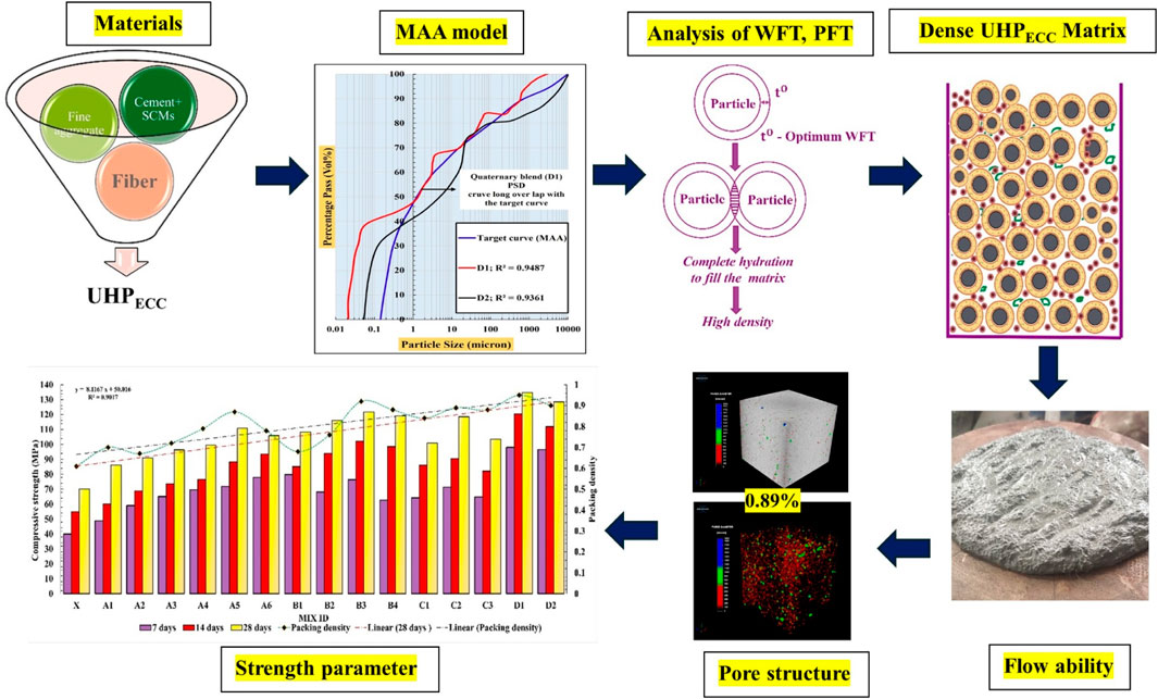
This paper presents the development of Ultra High Performance Engineered Cementitious Composites (UHPECC) through optimized Supplementary Cementitious Materials (SCMs) blends with cement and silica sand. Utilizing the Modified Andreasen and Andersen (MAA) model with Water Film Thickness (WFT) and Paste Film Thickness (PFT) analysis improves flowability and strength, reducing experimental trials. Experimental results showed that optimizing mix proportions using WFT and PFT evaluations increased packing density by up to 35.78% and reduced pore volume by 88.2% in the UHPECC matrix. CT scan analysis revealed a pore percentage of 7.5% and a compressive strength of 70 MPa in the conventional mix (X). However, incorporation of SCMs in composites significantly decreased pore percentage from 7.5% to 0.89% and achieved a compressive strength of 134.72 MPa. This study highlights the important role of SCMs selection and optimal quantity in enhancing properties of UHPECC, including packing density, mechanical performance, and porosity reduction.
1 Introduction
In traditional concrete, cement primarily serves as a binding material. In the 1990s, Victor Li pioneered the development of Engineered Cementitious Composites (ECC) by incorporating cement and Supplementary Cementitious Materials (SCMs) in a binary blend, resulting in a compressive strength of 70–90 MPa, which exceeded that of traditional concrete (Li and Leung, 1992). Further advancements in material mix design for cementitious composites, utilizing the Particle Packing Model (PPM) for optimization, have improved compressive strength beyond 120 MPa, leading to the development of Ultra High Performance Engineered Cementitious Composites (UHPECC) which are used in various applications such as shotcrete, off-site precasting, and the extrusion of structural members. Achieving excellent performance in UHPECC requires careful selection and optimization of material combinations to create a dense matrix (Li, 2007; Li, 2019). These combinations typically include SCMs such as glass powder, fly ash, marble dust, slag, iron ore powder, silica fume, silica sand, and both synthetic and steel fibers, which collectively enhance the composites’ mechanical strength and durability (Liu et al., 2017; Li et al., 2019; Huang et al., 2021; Abbass and Iqbal Khan, 2022; Wu et al., 2022; Zhao et al., 2023; Chen et al., 2024; Salahaddin et al., 2024).
Traditional UHPECC mix designs rely on trial-and-error, leading to high costs. To optimize material proportions, novel approaches focus on dense particle packing enhancing workability and mechanical strength (Shanmugasundaram and Praveenkumar, 2021; Alani et al., 2022). For instance, (Zhu et al., 2020; Yin et al., 2023 proposed a mix proportion based on the Modified Andersen and Andreasen (MAA) model, achieving 155 MPa compressive strength with good flowability. The MAA model utilizes a continuous particle distribution, optimizing particle arrangement from small to large, which enhances mechanical strength and durability. Similarly, (Fan et al., 2022 proposed a solid-liquid base packing model optimizing Water Film Thickness (WFT), reducing matrix porosity by 7.07%. Utilizing the MAA model, a reduced water-to-binder ratio resulted in an optimal WFT, minimized total pore volume, and significantly improved compressive strength, which increased from 52.31% to 58.38% (Fung and Kwan, 2010). For instance, (Wu et al., 2022), examined waste glass powder (WGP) as a partial binder replacement (≤30%, <75 µm) in ultra-high-strength cementitious composites. A 10% WGP replacement enhanced compressive strength beyond 150 MPa, whereas a 30% replacement increased cracking and reduced strength. Similarly, Salahaddin et al. (2024) replaced 20% cement with WGP, enhancing microstructure, and added 0.75% basalt fiber, achieving >100 MPa strength and excellent fresh properties. These studies underscore the eco-benefits of waste-based SCMs in UHPECC. Furthermore, Abbass and Iqbal Khan (2022) incorporated SCMs in a ternary blend (fly ash, silica fume, and quartz) with polyvinyl alcohol (PVA) fibers, resulting in excellent mechanical strength. Additionally, Zhao et al. (2023) validated the mechanical behaviour of ECC incorporating 2% of PVA fiber with crumb rubber and fly ash. These findings from the results contributed to waterproof reinforcement applications. The addition of glass powder and silica fume effectively improved packing density, with typical replacement levels ranging from 5% to 30%. Glass powder (GP) fills the gaps between cement particles, while silica fume (SF) occupies spaces between cement and glass powder particles, thereby enhancing packing density (Zhang et al., 2024). Similarly, Fan et al. (2020) designed a low-carbon UHPC using gold tailings, SF, and limestone powder, optimizing the mix design with the MAA model to achieve a dense matrix with minimal porosity, resulting in a compressive strength exceeding 130 MPa. A binder combination using cement with SF and quartz filler (median size of 3.5 µm) achieved a compressive strength exceeding 90 MPa while reducing the matrix pore volume (Alyousef et al., 2023; Liu et al., 2020) utilized recycled concrete powder and silica sand (particle size below 120 µm) as fillers in UHPECC. The results showed that fully replacing silica sand achieved higher strength compared to other filler combinations. Further, Wang et al. (2019) added river sand with a particle size less than 1.8 mm to UHPC, achieving excellent workability and compressive strength of over 120 MPa. Similarly, Fan et al. (2020) used river sand with particles less than 1.25 mm, and in a quaternary blend, this improved packing density and reduced porosity.
1.1 Mechanism behind the water film thickness and paste film thickness
Optimized water content and reactive cementitious materials play a crucial role in improving the strength (German, 1989; Indhumathi et al., 2022; Wang et al., 2023). Importantly, in UHPECC matrix consist of meso to macro size solid particles and liquid phase (water and HRWR). During the hydration process the water are formed thin layer around the solid particles is called WFT. The thickness of the water film is categorized as large (tL), and optimal (tO) described in Figure 1. An excessively large WFT (tL), typically resulting from a high w/b ratio, increases the spacing between C-S-H particles, dilutes the C-S-H gel with excess water, and reduces the packing density (Jones et al., 2002; Kwan and Li, 2014). Such conditions are commonly observed in conventional cementitious compositions. Conversely, when the WFT is optimal, hydration products effectively fill the pores in the matrix, contributing to the formation of a dense paste film thickness (Kwan et al., 2010; Salahaddin et al., 2024). At the nano- and micro-scale, the optimal WFT facilitates the filling of pores through the formation of C-S-H gel, thereby enhancing the overall matrix density.
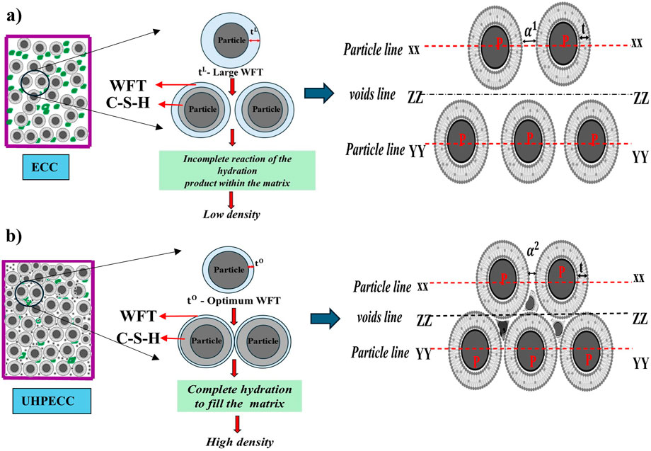
Figure 1. Schematic illustration of the effect of WFT on the density of the (a) ECC (b) UHPECC matrices.
Furthermore, the arrangement of particles within the UHPECC matrix is crucial for achieving a dense structure (German, 1989). detailed the segment-wise particle arrangement in the overall packing mixture. A high packing density was achieved by varying the particle sizes within each segment. He also introduced the concepts of random and dense pack lines, indicating that particles arranged in strings with large gaps between them result in lower packing density while particles arranged with smaller gaps in strings result in higher packing density (Jones et al., 2002). Figures 1a,b depict the packing system of normal cementitious composites and the enhanced packing system of UHPECC. Consider three lines in the matrix: the particle line at the top layer (XX), the voids line (ZZ), and the particle line at the bottom (YY). The particle line refers to the number of particles aligned either closely or exactly on the same line (German, 1989). The voids line indicates no particle present in the zone (ZZ), considered as voids. Distances α1and α2 denote the distance between two WFT around the particles. This distance is higher in normal composites due to excess water, resulting in a thicker film than in UHPECC described in Figure 1 (Kwan and McKinley, 2014). The hydration system in UHPECC, characterized by multi-size WFT around the cementitious particles due to the addition of different-sized particles, enhances the density of hydration products (Paul and John, 2023; Gayathiri and Praveenkumar, 2024). Therefore, particle packing analysis is vital to determining the optimal material usage in UHPECC for developing sustainable and eco-friendly concrete (Om, 2024; Shi et al., 2020).
The process for determining WFT is defined as the ratio of the excess water to the specific surface area of all solid ingredients, as shown in Equation 1 (Li and Kwan, 2013; Maalej et al., 2005). Additionally, the excess water ratio is calculated from the Equation 4. Furthermore, the amount of paste required to develop the surface layer of aggregates is referred to as the paste film thickness (PFT), defined as the ratio of excess binder paste to the specific surface area of the aggregate, as described in Equation 2 (Liu et al., 2020).
where
In traditional construction methods, structural deterioration issues such as permeability, shrinkage, spalling, and cracking reduce the strength and durability. The formation of pores and cracks is influenced by loose particle alignment, the selection of SCMs, and a low amount of hydration products in the matrix. Identifying these problems through microstructure and porosity analysis helps enhance structural stability. This research focuses on improving matrix densification by optimizing the solid particle and liquid phase distribution using the MAA particle packing model, WFT and PFT. Additionally, it explores the efficient utilization of silica fume (SF), marble dust (MD), glass powder (GP), silica sand, and 2% PVA fiber in UHPECC production. The mix proportion is validated using the goodness of fit (R2) through the least squares method to ensure optimization reliability. This study evaluates the fresh and mechanical properties and microstructure of UHPECC. Furthermore, CT scan analysis is conducted to verify matrix densification and porosity reduction achieved through the incorporation of SCMs.
2 Experimental program
2.1 Materials characterization
This study explored the incorporation of silica fume (SF), marble dust (MD), and glass powder (GP) as SCMs in UHPECC. Table 1 detailed the chemical compositions and physical properties of the cementitious materials used in this study. Figure 2 represent the methodology of material characterization for UHPECC. Ordinary Portland cement (OPC) was utilized following the Indian Standard IS 12269:2013. The particle sizes of binder were determined using a Malvern 2000 laser diffraction particle size analyzer, following ISO 13320–2020 standards, with the results presented in Figure 3a. Notably, SF and GP exhibit the highest silica content, at 92.5% and 70.38%, respectively. X-ray Diffraction (XRD) and Field Emission Scanning Electron Microscopy (FE-SEM) analyses reveal that both SF and GP are predominantly amorphous, while MD also shows amorphous characteristics and contains a significant amount of calcium carbonate (CaCO3), as illustrated in Figure 3b,4. The BET surface area analysis provided data on the fineness of the binders. Silica sand was employed as the fine aggregate with a maximum particle size of 300 μm. Additionally, polyvinyl alcohol (PVA) fiber, with a diameter of 39 μm and a length of 8 mm, were included in the mix, as specified in Table 2. A poly carboxylic ether based High Range Water Reducer (HRWR) was used to achieve the desired workability with various water/binder ratio.
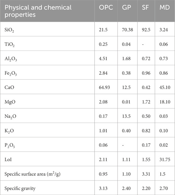
Table 1. The weight percentages of various chemical compositions and physical properties of the cementitious materials used in this study.
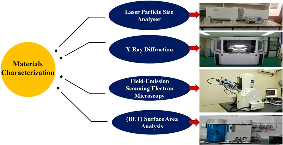
Figure 2. Methodology for material characterization for UHPECC.
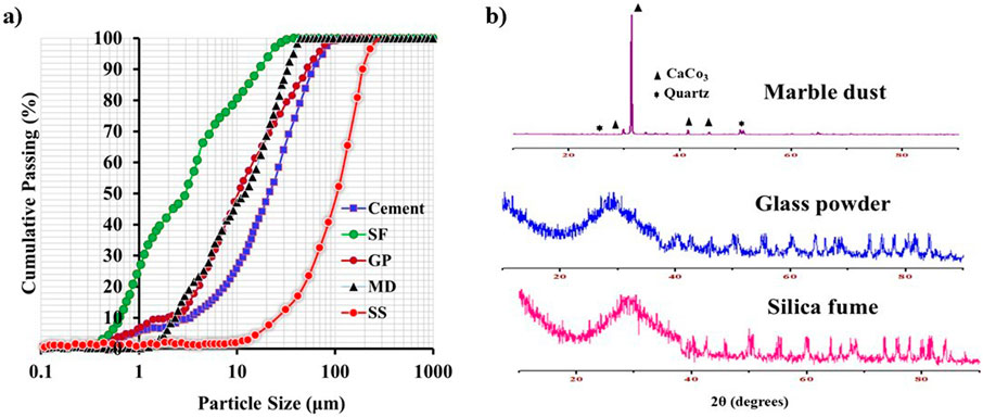
Figure 3. (a) Particle size distribution and (b) X-ray diffraction (XRD) analysis of cementitious materials.
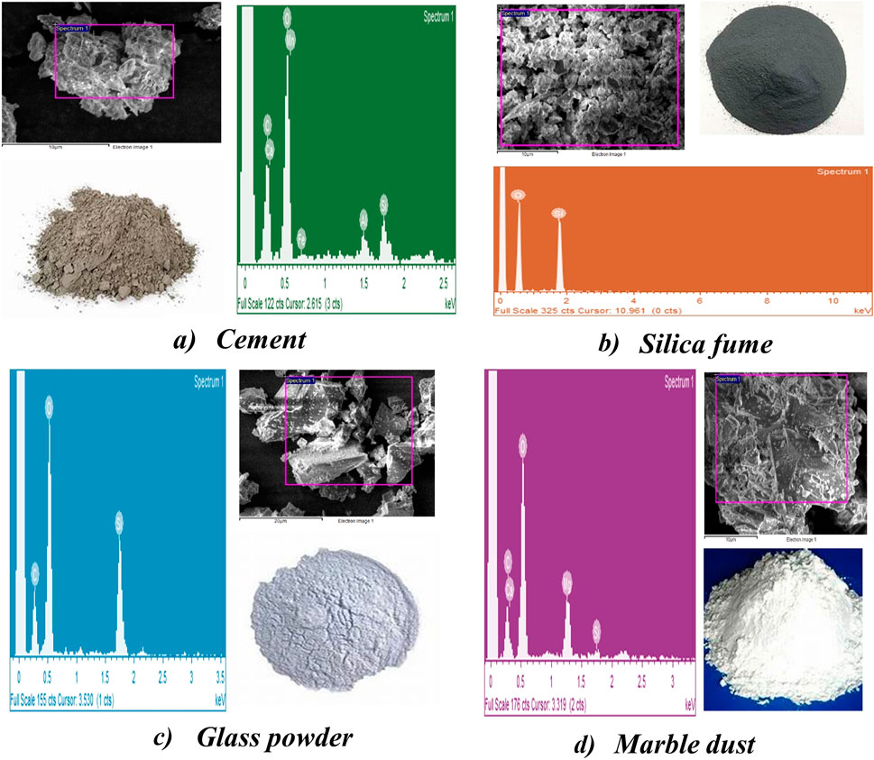
Figure 4. FE-SEM image of cementitious materials used in UHPECC development. (a) Cement (b) silica fume (c) glass powder (d) marble dust.

Table 2. Properties of PVA fiber.
2.2 Mix design
The MAA model is the effective packing model for determining the materials composition for a dense matrix (Karadumpa and Pancharathi, 2021; Santhanam, 2003). This approach combines particles of various sizes to fit as densely as possible, thereby minimizing void (EMMA User Guide Version 1 User Guide Elkem Materials Mixture Analyser-EMMA, 2025). Equation 5, known as the MAA equation, is used to calculate the high packing density for a multi-blend composition of raw materials:
In this equation, the distribution modulus (q) varies from 0.2 to 0.3 and is associated with the mix’s rheological properties. A higher q value indicates a coarser, less workable mix, while a q value is low, more finer and more workable mix. In this study of the mix design of UHPECC, the distribution modulus q is set at 0.23 (Santhanam, 2003). CPP refers to the cumulative percentage of particles finer than the D, Dmax, Dmin, refer to the composed material’s maximum and minimum particle sizes, respectively. After determining the optimal mix proportion and comparing it with the target curve, the fit is assessed using the Least Squares Method (LSM), with the fitting degree R2 expressed in Equation 6. An R2 value near 1 indicates that the PSD curve of the composed material closely fits the target curve, signifying dense packing.
where PR and TC represent the predicted and target cumulative percentage of particles. T is the mean of the target cumulative percentage.
2.3 UHPECC sample preparation process and curing condition
A portable mixer machine operating at low, medium, and high speeds prepared all the mixes in this study. All raw materials, including GP, SF, MD, cement, and silica sand, were first premixed in a dry state at low speed. Then, 75% of the water was added to the dry mix and blended at medium speed to ensure uniformity. The remaining 25% of water and the HRWR were added in to mix. Finally, the PVA fibers were slowly introduced, and the mixture was blended at high speed to achieve the desired consistency (Huang et al., 2021), as depicted in the mixing timeline shown in Figure 5a. To evaluate the rheological properties of the fresh paste, a mini flow table test was conducted according to ASTM C1856 (Standard Practice for Fabricating and Testing Specimens of Ultra-High-Performance Concrete, 2017). The fresh UHPECC was poured into molds. After 24 h, the specimens were placed in a hot water curing chamber. During the initial phase, known as the preheating stage, the temperature was gradually increased over 2 h. The specimens were then subjected to a temperature of 90°C for 8 h and cooled to room temperature as detailed in Figure 5b. The specimens were then moved to standard curing conditions until the final testing age (Shen et al., 2019).
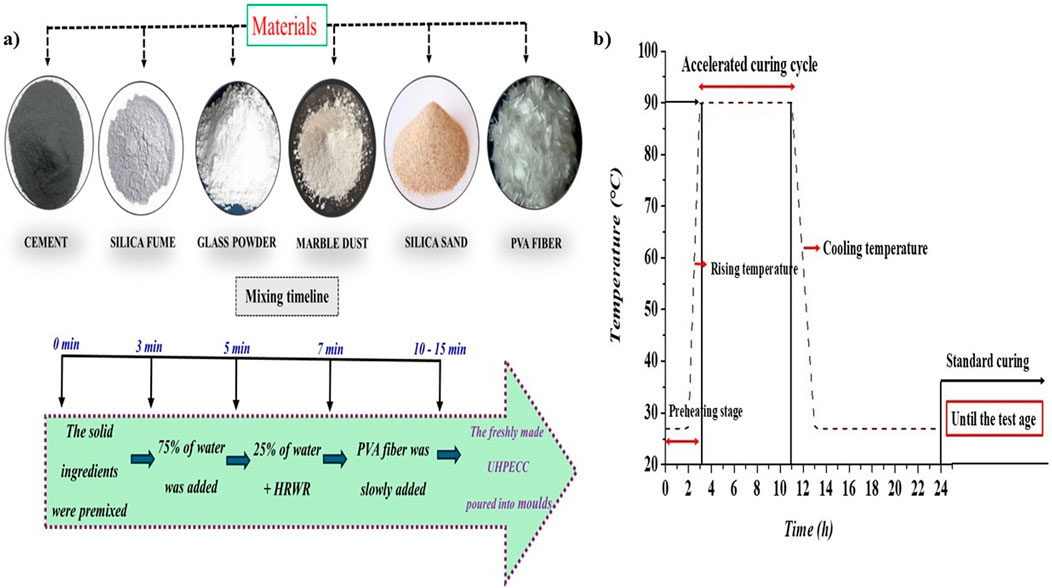
Figure 5. (a) The production process and (b) Curing cycle history of UHPECC.
3 Test setup for pore percentage evaluation of UHPECC
In this study, the analysis of pores within UHPECC was conducted using a CT scan with specimen size 50 × 50 × 50 mm, as described in Figure 6. The CT scan offers a significant advantage in evaluating the internal structure of UHPECC. For example, Wang et al. (2019) utilized X-ray CT scans to analyze the pore sizes of UHPC specimens, focusing on pores larger than 50 µm. They concluded that employing the particle packing method helps to reduce pore formation in the UHPECC matrix. Similarly, Qiu et al. (2020) investigated crack patterns in engineered cementitious composites with fiber reinforcement by examining specimens cut from tested uniaxial tensile samples analyzing crack patterns and flaw widths after testing. Their analysis demonstrated that adding fly ash along with PVA fiber reduces crack formation. In this study, the UHPECC specimens were scanned using the Bruker SkyScan 1273 industrial CT scanner, as shown in Figure 6. This system is specifically designed for analyzing the internal structure of materials such as metals and concrete. It utilizes an X-ray source with a focused beam, typically set at an energy level of 130 kV and 115 μA, which is capable of penetrating the dense UHPECC matrix. The UHPECC specimen is carefully positioned on a rotating stage within the scanner. As X-rays pass through the specimen, they interact with the material, being absorbed or scattered depending on the density of the UHPECC matrix. Based on the differences in X-ray intensity, it helps to detect the pores and solid phase. A tungsten detector captures these variations from that reflect X-ray signals rays passing through different parts of the sample, layer by layer, and converts them to digital data. The SkyScan 1273 system processes this digital data and reconstructs it into a 3D image. All UHPECC specimens were examined using the CT scan and their internal structures were compared with strength parameters. This testing method is applied for various purposes, including protective barriers for defense applications, anti-corrosion applications for marine and coastal structures (Qiu et al., 2020) and repair and rehabilitation of infrastructure (Choucha et al., 2018).
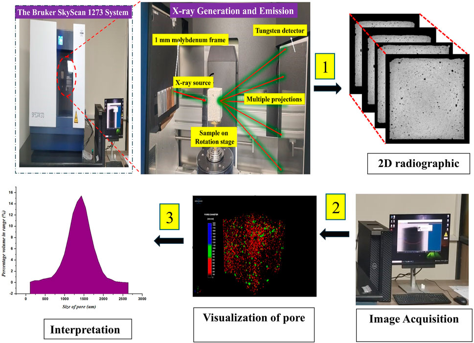
Figure 6. Schematic diagram of the CT-Scan analysis process.
4 Result and discussion
4.1 Validation of mix optimization using PPM
The packing density of UHPECC with the addition of SCMs was simulated using the Elkem Materials Mixture Analyzer (EMMA), which incorporates the MAA particle packing model. In this simulation, mix combinations were divided into three phases: binary, ternary, and quaternary levels of binder, as shown in Table 3. Based on the EMMA analysis, 15 mix proportions were designed with varying amounts of SCMs and cement. The water/binder ratios ranged from 0.14 to 0.22, and the HRWR content varied up to 5.2% of the binder proportion. Additionally, 2% PVA fiber was included in the total mix volume, as indicated in Table 3. The table reveals cement replacements with various types of SCMs, ranging from 7.5% to 30%. The binder pastes volume (BPV) the sum of the volumes of binder, water, and HRWR varied from 42% to 65%.
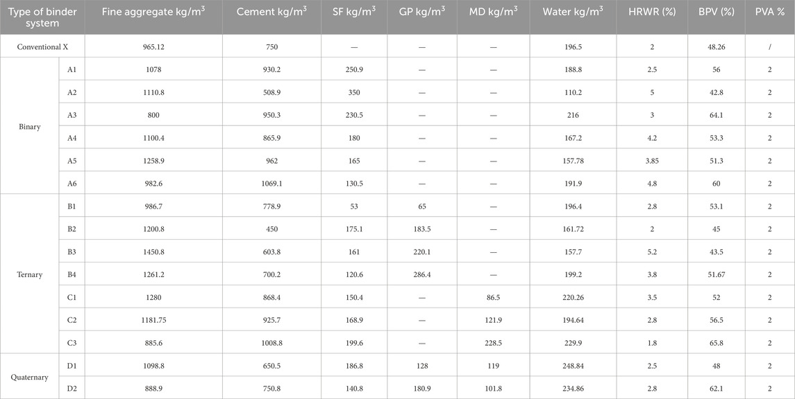
Table 3. Material proportion for UHPECC.
Figure 7a illustrates the binary blend of particle size distribution (PSD) curves aligning with the smooth blue target curve, using materials such as cement, SF, and silica sand as filler. The PSD curves for different mixes A1, A2, A3, A4, A5, and A6 show that curve A5 fits closer to the target curve than other binary mix PSD curves by adjusting the quantities of binder and filler materials. The goodness of fit (R2) values for curves A1 to A6 range from 0.89 to 0.92 using the least squares method, with the A5 binary mix PSD curve achieving an R2 of 0.92. The next set of ternary blends of material mix PSD curves is shown in Figures 7b,c. Ternary binders like cement, SF and GP are labelled B1, B2, B3, and B4, while ternary binders with cement, SF, and MD are labelled C1, C2, and C3. Figure 7b show that PSD curves B3 achieve R2 values of 0.9256 compare than all ternary mix. Finally, the quaternary mix with cement, MD, GP, and SF, labelled D1 and D2, demonstrates good correlation with all binder combinations, achieving R2 values of 0.94 and 0.93, with more overlap with the target curve, as shown in Figure 7d. The incorporation of GP in ternary and quaternary blends, guided by the MAA model, allows for tailored particle size distributions that closely align with the target curve. As seen in the R2 values of up to 0.94 in quaternary mixes, these materials effectively improve packing density and reduce voids.
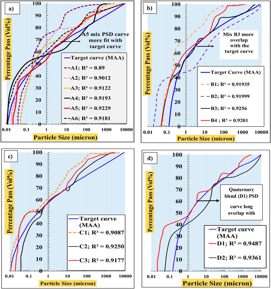
Figure 7. Graphical output of MAA model: (a) Binary Mix Proportion (cement +SF) (b) Ternary Mix Proportion (cement+GP+SF) (c) Ternary Mix Proportion (cement+MD+SF) (d) Quaternary Mix Proportion (cement+MD+SF+GP).
4.2 Flow spread
UHPECC exhibits unique properties and has various practical applications, with flowability being one of the key properties (Salahaddin et al., 2024). In this study, the flowability of fresh UHPECC mixtures was evaluated using the mini flow table test according to ASTM C 1856 (Standard Practice for Fabricating and Testing Specimens of Ultra-High-Performance Concrete, 2017). During the test, the spread diameter of the fresh UHPECC was measured in different flow directions, and the mean values of these measurements were calculated to determine the spread values. Figure 8 illustrates the spread values for binary, ternary, and quaternary binder blends, which range from 176 mm to 245.
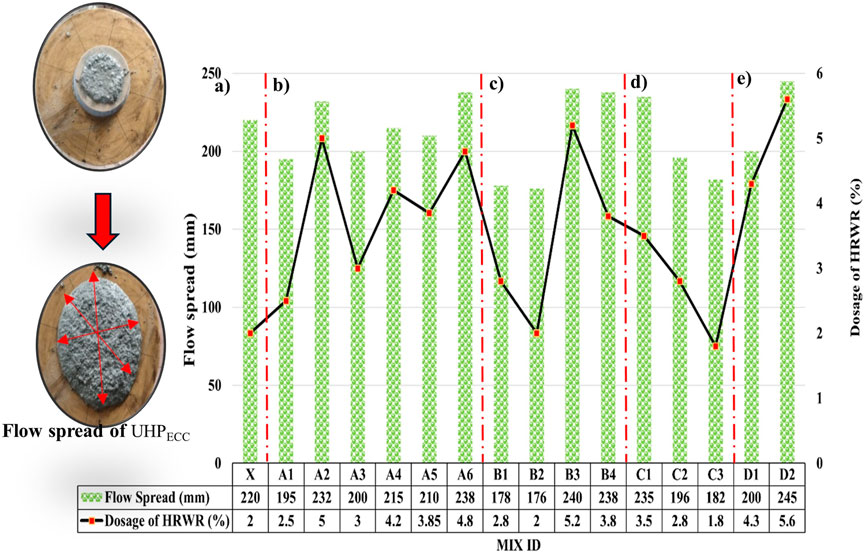
Figure 8. Flow spread for fresh UHPECC (a) Conventional mix, (b) binary blends, (c,d) ternary blend, and (e) quaternary blend.
In Figure 8a, the conventional mix achieved a spread value of 220 mm with 2% HRWR and the absence of SCMs. Figure 8b presents the spread values for binary blends (cement + SF) of UHPECC with HRWR dosages ranging from 2.5% to 5%. The binary blend A6 achieved a high spread value of 238 mm with the addition of 4% HRWR and 7.5% SF. Conversely, mix A1 exhibited a lower spread value due to the combination of a high SF content and a low HRWR dosage. Furthermore, the spread values for ternary blends, from mix B1 to C3, ranged from 176 mm to 240 mm, as detailed in Figures 8c, d. Among the ternary blends, mix B3 achieved the highest spread value compared to all binary and ternary combinations by adjusting the material proportions to 7.76% SF, 9.73% GP, and 5.2% HRWR. The optimal amounts of SF and GP reduced inter-particle friction and provided a smoother surface compared to cement, MD and fine aggregates. Finally, the quaternary blends D1 and D2 achieved spread values of 200 mm and 245 mm, respectively, as shown in Figure 8e. In the observed test, the Mix D2 achieved a smooth flow with a longer spread dimension. In conclusion, the mini flow table test results indicate that mix A6 (binary blend), B3 (ternary blend), and D2 (quaternary blend) achieved high spread values, which suggests superior transport properties.
4.3 WFT and PFT
4.3.1 Effect of WFT and PFT on flow spread
To analyze the Water Film Thickness (WFT) and Paste Film Thickness (PFT), material properties such as particle size and specific surface area are determined using laser particle size analysis and BET analysis, which are incorporated into Equations 1,2, for calculating WFT and PFT. Additionally, WFT, PFT, excess paste ratio, and excess water ratio are influenced by factors such as packing density, water content, HRWR dosage, fiber content, and the physical properties of solid materials (Liu et al., 2020). Notably, analyzing WFT and PFT plays a crucial role in improving the ultra-high strength and fresh properties of UHPECC mixtures (Kwan and Li, 2014). Table 4 shows the specific values for WFT and PFT for UHPECC mixtures.
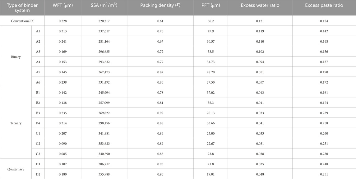
Table 4. Flowability vs WFT and PFT.
The data shows that as the water content increased from 110.2 to 229.9 kg/m3, the WFT also increased progressively from 0.085 to 0.241 µm. Additionally, Figure 9 demonstrate the relationship between WFT, PFT, and flow spread. The data points in Figure 9a indicate that a rise in the WFT measurement had a significant impact on the increase in flow spread. The conventional mixture achieved WFT 0.228 μm and achieved a flow spread of 220 mm. According to ASTM C 1856 (Standard Practice for Fabricating and Testing Specimens of Ultra-High-Performance Concrete, 2017), the flow spread for ultra-high-performance cementitious composites should typically range from 200 to 250 mm. In the binary combination (cement+SF), mixes A1 to A6 showed WFT values ranging from 0.145 to 0.238 µm, with mix A6 achieving the highest WFT and flow spread compared to other binary mixes. The addition of GP and MD further increased WFT and flow spread. In the quaternary combination of cement+SF+GP+MD, mix D2 achieved the highest flow spread with the WFT of 0.180 µm, compare than binary and ternary mixtures. The values for PFT and excess paste ratio shown in Table 4 vary from 19.01 to 56.2 μm. The results from the mini flow table test indicate that the WFT, PFT, and flow spread are interdependent. The formation of WFT and PFT depends on the absorption and dispersion of water and HRWR around the surface of solid particles. High WFT and PFT increase the flow spread but reduce the packing density, as detailed in Figure 9b. High WFT results in larger particle spacing, which decreases the capacity for close packing. Determining the optimum WFT and PFT is crucial for achieving high packing density. The conventional mix X, achieves a low packing density of 0.61 due to its high PFT. Optimization using the MAA packing model, with the addition of supplementary cementitious materials (SCMs), improves the packing density up to 0.95. Mix D1, a quaternary combination of 11.5% SF, 7.8% GP and 7.03% MD, achieves a high packing density with a flow spread of 200 mm and a PFT of 21.8 µm. Furthermore, the optimum WFT and PFT values were validated by examining the strength parameters and pore reduction. The upcoming section discusses the improvement in mechanical strength and the reduction in pore percentage in the UHPECC matrix.
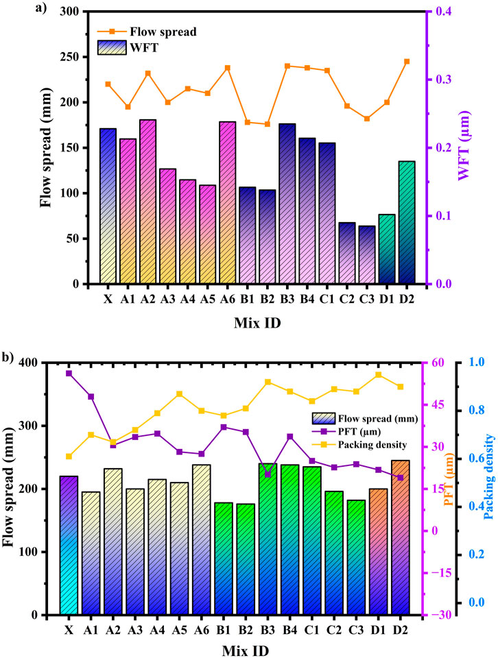
Figure 9. Relation between (a) WFT vs flow spread (b) PFT Vs Packing density.
4.4 Results on compressive strength
Figure 10 presents the compressive strength results of conventional, binary, ternary, and quaternary mixtures of UHPECC under accelerated curing conditions. Accelerated curing reduces the amount of unhydrated product in matrix and increases strength. To demonstrate the reliability of the MAA packing model, it is crucial to validate the mechanical strength of optimized UHPECC. Figure 10 illustrated the correlation between the packing density and compressive strength at 28 days, achieving an R2 value of 0.9017.
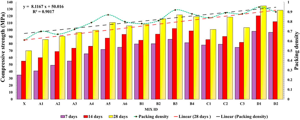
Figure 10. Compressive strength of UHPECC specimen.
Compared to the conventional mix, the mixtures with SCMs increase in compressive strength was observed. The conventional mix of UHPECC was achieved 70 MPa. Among binary blends A1 - A6, A5 achieved the highest compressive strength, with a 36.78% increase and a packing density of 0.87, compared to other binary and conventional mix. The A5 mix, optimized using the MAA packing model, included 8.75% SF, 55.41% fine aggregate, and 2% PVA fiber. Furthermore, the addition of GP in the UHPECC matrix enhanced packing density and improved strength parameters. The B3 mix achieved a compressive strength of 121.8 MPa with a packing density of 0.92, surpassing both binary and conventional UHPECC mixes. This mix contained 9.73% GP and 7.76% SF, optimized by the MAA packing model. The optimal combination of GP and SF contributed to the pozzolanic reaction, reducing calcium hydroxide production during hydration. However, a reduction in compressive strength of 28 days was observed in ternary blends of MD with SF compared to the GP+SF combination. The strength reduction is attributed to MD primary composition of CaCO3, which has a lower pozzolanic activity than other SCMs, leading to reduced C-S-H production compared to the GP-SF combination. The results indicate that mix D1 achieved the highest compressive strength at 134.72 MPa, with a quaternary combination of cement (31.88%), MD (7.03%), GP (7.8%), and SF (11.5%). The appropriate proportions of SCMs and PVA fiber in UHPECC resulted in dense packing and high compressive strength. Similarly, PFT and WFT play an important role in strength development. In this study, mix D1 achieved a high compressive strength with a water film thickness (WFT) of 0.119 μm and a paste film thickness (PFT) of 25.8 μm, as illustrated in Figure 11. Although some mixtures exhibited higher PFT values than D1, this led to excessive slurry formation and reduced compressive strength. For example, mix X exhibited a high PFT in the absence of SCMs. This is because cement, having relatively larger particle sizes, becomes the primary binder component in the absence of SCMs, resulting in an increased volume of paste coating around sand particles and fibers. The addition of blended materials such as SF, GP and MD optimized using the MAA model, significantly improved packing density, achieved optimal WFT and PFT, and enhanced compressive strength. Analyzing the relationships among WFT, PFT, fresh properties, and mechanical performance provides valuable insights into the sustainable development of UHPECC. The following section discusses CT scan test results, which demonstrate pore reduction achieved through the MAA model optimization.
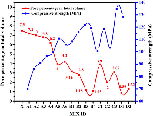
Figure 11. Relation between compressive strength with packing density and PFT.
5 Porosity and structure distribution analysis
In this study, CT scan analysis is employed to evaluate the thickness distribution within the internal matrix of UHPECC. This technique allows for the visualization and quantification of pores across different layers of the UHPECC structure. Figure 13 illustrates the different structure thicknesses in the UHPECC matrix, including dense matrix, clinker, and pores at the mesoscopic scanning level. Additionally, Figure 13a presents the structure thickness distribution for conventional and binary blends of UHPECC. The CT-scan revealed that the range of structure thickness exceeded 2500 μm, indicating a high presence of pores and unhydrated cement clinkers. To reduce the pores, the addition of GP and MD to the cement and SF combination in the ternary mix was evaluated. Figures 13b,c show that mesoscopic structure thickness was higher than microscopic thickness, suggesting the reduction of micro-pores due to the filling effect of GP and MD. In this combination, mix B3 achieved a high compressive strength of 121.8 MPa and decreased pore percentage to 1.18%, as detailed in Figures 12, 14. In the quaternary blend of cement + MD + GP + SF, Figure 13d show that a high percentage of structure thickness fell between 1 nm and 200 μm, and the pore percentage was reduced to 0.89%. Figure12 illustrates the relationship between pore percentage and compressive strength, confirming that the MAA packing model effectively reduces pores and enhances UHPECC performance. The highest compressive strength of 134.72 MPa with a low pore percentage of 0.89% was achieved in the quaternary blend (Mix D1). The 3D pore structure of the UHPECC specimen, as depicted in Figure 14, highlights the benchmark mixes of UHPECC for effective pore reduction across binary, ternary, and quaternary combinations.
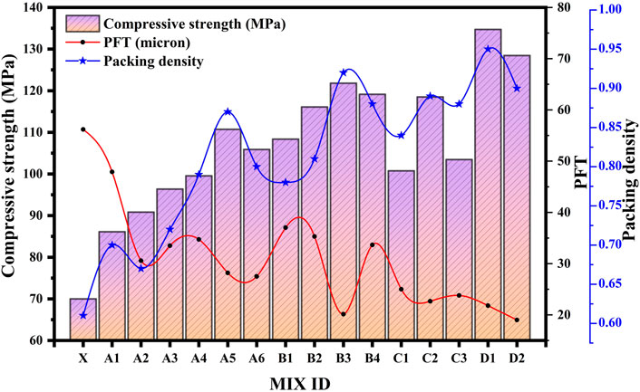
Figure 12. Relation between pore percentage and compressive strength of UHPECC.
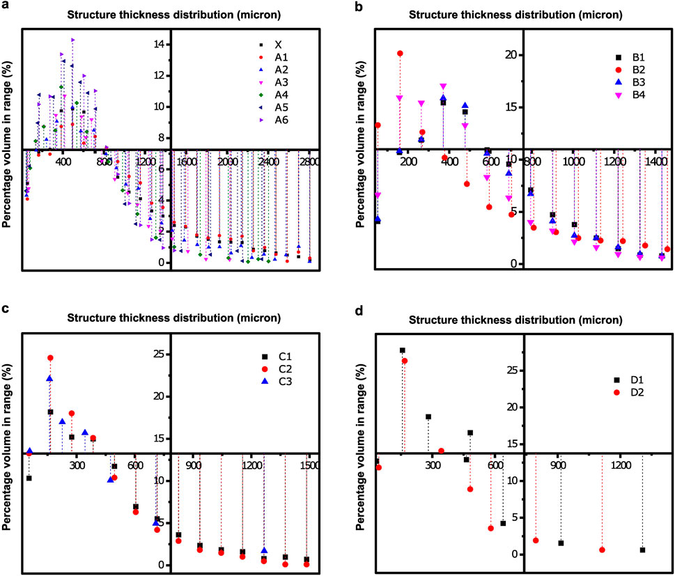
Figure 13. The structure thickness of specimen (a) conventional and binary mix (cement + SF), (b) ternary mix (cement+SF+GP), (c) ternary mix (cement+SF+MD), (d) quaternary mix (cement+SF+GP+MD).
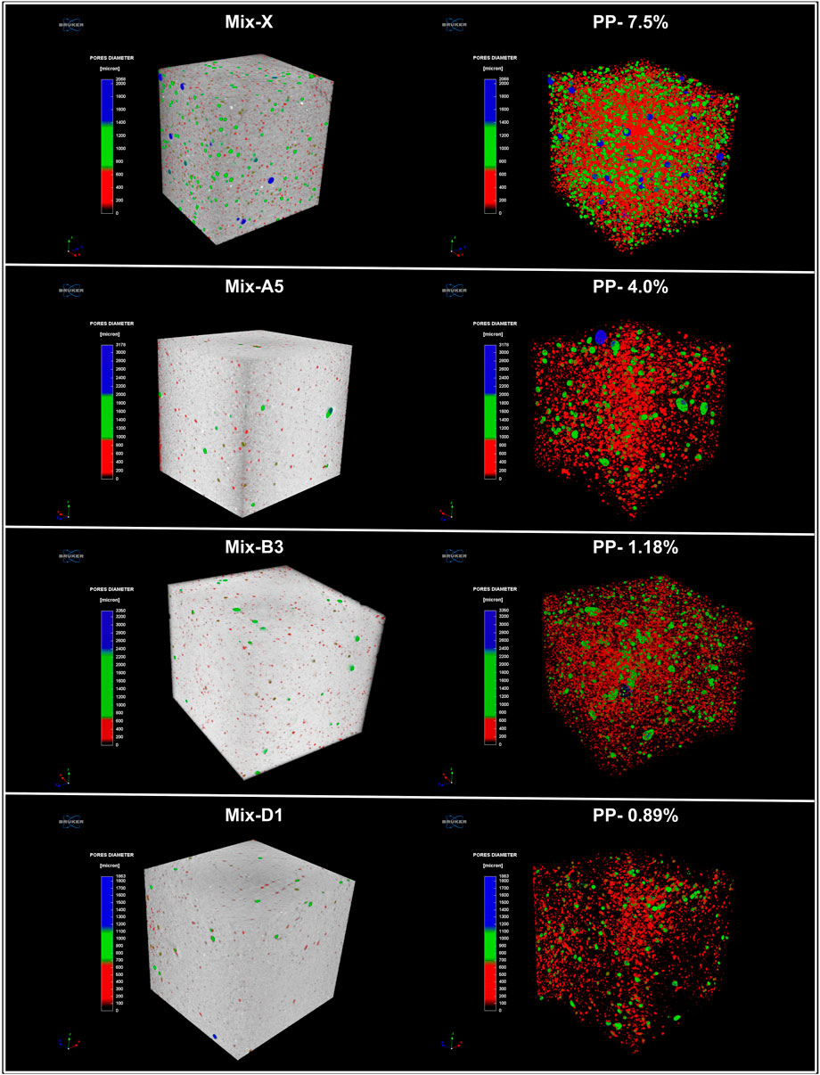
Figure 14. 3D visualization of a CT-scanned UHPECC specimen highlights the pore reduction benchmark, such as MIX ID–X, A5, B3 and D1. (PP- Pore Percentage).
6 Microstructure
Scanning electron microscopy (SEM) analysis was utilized to investigate the microstructure of the UHPECC matrix and to evaluate the roles of SCMs and PVA fibers, as depicted in Figure 15. Figure 15a illustrates the microstructure of the conventional UHPECC mix (Mix ID X), revealing a cluster of pores near the aggregate-paste interface. These pores result from insufficient particle packing due to the absence of SCMs, leading to increased porosity and lower compressive strength compared to all other mixes. This phenomenon was further confirmed by CT scan pore size analysis, which measured a 7.5% pore in the conventional mix.
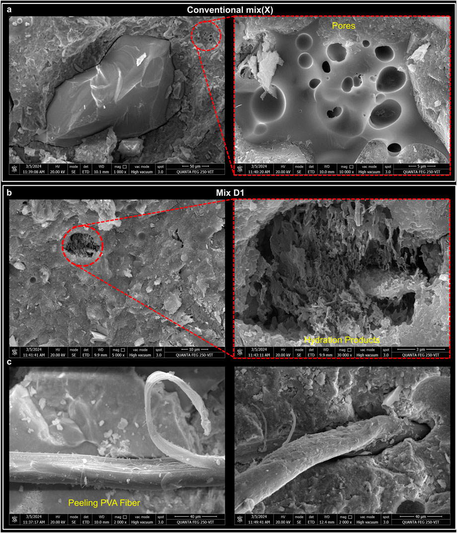
Figure 15. SEM image of the hardened UHPECC (a) mix ID X, (b,c) Mix D1.
On the other hand, the incorporation of SCMs such as SF, GP and MD enhanced the production of C-S-H gel, which gradually increased the compressive strength by up to 48% compared to conventional mixes. Additionally, hot water curing accelerated the reaction between calcium and silica present in the SCMs, promoting further hydration product precipitation around cement particles. Specifically, Mix D1, incorporating a quaternary combination of SCMs, showed significant improvement in pore filling, with hydration products distinctly observed in Figure 15b. The CT scan analysis further validated this finding, revealing a reduced pore percentage of 0.89% for Mix D1. The Figure 15c provides a detailed view of UHPECC with PVA fibers under compressive load. The SEM images clearly show fiber peeling, as well as hydration products on fiber surface. During compression, PVA fibers effectively absorbed and transferred load-induced energy. Notably, no visible cracks were observed near the hardened paste after failure, contributing to a compressive strength of 134.72 MPa. Furthermore, no fiber agglomeration was detected, confirming the uniform dispersion of fibers during the mixing process. Based on SEM and CT scan analyses, it can be concluded that the incorporation of SCMs significantly refined the pore structure, thereby improving both mechanical strength and durability of UHPECC.
7 Conclusion
The study achieved minimal porosity and enhanced compressive strength using the MAA packing concept. Optimized SCMs, cement, low W/C ratio, HRWR, and fine aggregates further improved UHPECC performance. WFT and PFT analysis confirmed a denser microstructure with reduced porosity. The key conclusions are as follows:
• The EMMA optimization in the MAA packing model achieved a 0.95 packing density, reducing pore volume by up to 80%.
• The analysis of WFT and PFT helped to determine the optimal dosage of liquid components in the UHPECC mix and enhanced the microstructure.
• PVA fibers enhanced UHPECC compressive strength by improving matrix-fiber interaction and slowing crack propagation.
• The quaternary mix D1, consisting of 31.88% cement, 7.03% MD, 7.8% GP and 11.5% SF, achieved a dense microstructure with structural thicknesses ranging from 1 nm to 200 μm. This mix achieved compressive strength up to 134 MPa.
• This study optimized UHPECC mix design using the MAA packing model, increasing compressive strength and reducing porosity, as confirmed by CT scans and SEM analysis. Future research will focus on the tensile and flexural performance and durability under aggressive conditions.
Data availability statement
The original contributions presented in the study are included in the article/supplementary material, further inquiries can be directed to the corresponding author.
Author contributions
PK: Conceptualization, Data curation, Methodology, Resources, Software, Validation, Visualization, Writing – original draft, Writing – review and editing. SO: Investigation, Supervision, Validation, Visualization, Writing – review and editing.
Funding
The author(s) declare that no financial support was received for the research and/or publication of this article.
Acknowledgments
The authors wish to thank the School of Civil Engineering at Vellore Institute of Technology (Vellore) and the Department of Science and Technology, New Delhi, India, for providing support for the CT-scan facility through “Promotion of University Research and Scientific Excellence (PURSE)” under grant No. SR/PURSE/2020/34 (TPN56960) and carry out the necessary facilities for this research work.
Conflict of interest
The authors declare that the research was conducted in the absence of any commercial or financial relationships that could be construed as a potential conflict of interest.
Generative AI statement
The author(s) declare that no Generative AI was used in the creation of this manuscript.
Publisher’s note
All claims expressed in this article are solely those of the authors and do not necessarily represent those of their affiliated organizations, or those of the publisher, the editors and the reviewers. Any product that may be evaluated in this article, or claim that may be made by its manufacturer, is not guaranteed or endorsed by the publisher.
References
Abbass, W., and Iqbal Khan, M. (2022). Experimental and numerical investigation of flexural behavior of hybrid fiber reinforced high strength incorporating binary and ternary blend of ultra fines. Structures 42, 53–64. doi:10.1016/j.istruc.2022.05.116
Alani, A. H., Azmi Megat Johari, M., Tareq Noaman, A., Muhamad Bunnori, N., and Majid, T. A. (2022). Effect of the incorporation of PET fiber and ternary blended binder on the flexural and tensile behaviour of ultra-high performance green concrete. Constr. Build. Mater 331, 127306. doi:10.1016/j.conbuildmat.2022.127306
Alyousef, R., Abbass, W., Aslam, F., and Gillani, S. A. A. (2023). Characterization of high-performance concrete using limestone powder and supplementary fillers in binary and ternary blends under different curing regimes. Case Stud. Constr. Mater. 18, e02058. doi:10.1016/j.cscm.2023.e02058
Chen, Y., Tong, J., Li, Q., Xu, S., and Shen, L. (2024). Application of high-performance cementitious composites in steel–concrete composite bridge deck systems: a review. J. Intelligent Constr. 2, 1–23. doi:10.26599/jic.2024.9180012
Choucha, S., Benyahia, A., Ghrici, M., and Mansour, M. S. (2018). Effect of natural pozzolan content on the properties of engineered cementitious composites as repair material. Front. Struct. Civ. Eng. 12, 261–269. doi:10.1007/s11709-017-0394-x
EMMA User Guide Version 1 User Guide Elkem Materials Mixture Analyser-EMMA (2025). Available online at: www.elkem.com.
Fan, D., Tian, W., and Yu, R. (2022). Incorporation of liquid phase into solid particle packing model for precise design of low water/binder cement-based composites (LW/B-CC): modelling and experiments. Compos B Eng. 242, 110070. doi:10.1016/j.compositesb.2022.110070
Fan, D., Yu, R., Fu, S., Yue, L., Wu, C., Shui, Z., et al. (2021). Precise design and characteristics prediction of Ultra-High Performance Concrete (UHPC) based on artificial intelligence techniques. Cem. Concr. Compos 122, 104171. doi:10.1016/j.cemconcomp.2021.104171
Fan, D. Q., Yu, R., Shui, Z. H., Wu, C. F., Song, Q. L., Liu, Z. J., et al. (2020). A new design approach of steel fibre reinforced ultra-high performance concrete composites: experiments and modeling. Cem. Concr. Compos 110, 103597. doi:10.1016/j.cemconcomp.2020.103597
Fung, W. W. S., and Kwan, A. K. H. (2010). Role of water film thickness in rheology of CSF mortar. Cem. Concr. Compos 32, 255–264. doi:10.1016/j.cemconcomp.2010.01.005
Gayathiri, K., and Praveenkumar, S. (2024). Quaternary blended eco high performance concrete utilizing high volumes of siliceous additives. Constr. Build. Mater 430, 136389. doi:10.1016/j.conbuildmat.2024.136389
Huang, B. T., Weng, K. F., Zhu, J. X., Xiang, Y., Dai, J. G., and Li, V. C. (2021). Engineered/strain-hardening cementitious composites (ECC/SHCC) with an ultra-high compressive strength over 210 MPa. Compos. Commun. 26, 100775. doi:10.1016/j.coco.2021.100775
Indhumathi, S., Praveen Kumar, S., and Pichumani, M. (2022). Reconnoitring principles and practice of Modified Andreasen and Andersen particle packing theory to augment Engineered cementitious composite. Constr. Build. Mater 353, 129106. doi:10.1016/j.conbuildmat.2022.129106
Jones, M. R., Zheng, L., and Newlands, M. D. (2002). Comparison of particle packing models for proportioning concrete constituents for minimum voids ratio. Mater. Struct. 35, 301–309. doi:10.1617/13818
Karadumpa, C. S., and Pancharathi, R. K. (2021). Influence of particle packing theories on strength and microstructure properties of composite cement–based mortars. J. Mater. Civ. Eng. 33. doi:10.1061/(asce)mt.1943-5533.0003848
Kwan, A. K. H., Fung, W. W. S., and Wong, H. H. C. (2010). Water film thickness, flowability and rheology of cement-sand mortar. Adv. Cem. Res. 22, 3–14. doi:10.1680/adcr.2008.22.1.3
Kwan, A. K. H., and Li, L. G. (2014). Combined effects of water film, paste film and mortar film thicknesses on fresh properties of concrete. Constr. Build. Mater 50, 598–608. doi:10.1016/j.conbuildmat.2013.10.014
Kwan, A. K. H., and McKinley, M. (2014). Effects of limestone fines on water film thickness, paste film thickness and performance of mortar. Powder Technol. 261, 33–41. doi:10.1016/j.powtec.2014.04.027
Li, L. G., and Kwan, A. K. H. (2013). Concrete mix design based on water film thickness and paste film thickness. Cem. Concr. Compos 39, 33–42. doi:10.1016/j.cemconcomp.2013.03.021
Li, P. P., Cao, Y. Y. Y., Brouwers, H. J. H., Chen, W., and Yu, Q. L. (2019). Development and properties evaluation of sustainable ultra-high performance pastes with quaternary blends. J. Clean. Prod. 240, 118124. doi:10.1016/j.jclepro.2019.118124
Li, V. C. (2007). Engineered cementitious composites (ECC)-Material, structural, and durability performance.
Li, V. C. (2019). “Applications of engineered cementitious composites (ECC),” in Engineered cementitious composites (ECC) (Springer Berlin Heidelberg), 313–369. doi:10.1007/978-3-662-58438-5_9
Li, V. C., and Leung, C. K. Y. (1992). Steady-state and multiple cracking of short random fiber composites. J. Eng. Mech. 118, 2246–2264. doi:10.1061/(asce)0733-9399(1992)118:11(2246)
Liu, H., Sun, X., Du, H., Lu, H., Ma, Y., Shen, W., et al. (2020). Effects and threshold of water film thickness on multi-mineral cement paste. Cem. Concr. Compos 112, 103677. doi:10.1016/j.cemconcomp.2020.103677
Liu, H., Zhang, Q., Gu, C., Su, H., and Li, V. (2017). Self-healing of microcracks in Engineered Cementitious Composites under sulfate and chloride environment. Constr. Build. Mater 153, 948–956. doi:10.1016/j.conbuildmat.2017.07.126
Maalej, M., Ser, , Quek, T., and Zhang, J. (2005). Behavior of hybrid-fiber engineered cementitious composites subjected to dynamic tensile loading and projectile impact. J. Mater. Civ. Eng. 17, 143–152. doi:10.1061/ASCE0899-1561200517:2143
Om, S. (2024). A review on the influence of particle packing theory and materials on characteristics of ECC. J. Build. Eng. 98, 111079. doi:10.1016/j.jobe.2024.111079
Paul, A., and John, E. (2023). Study on the optimisation of cement and binder content to develop a sustainable high-performance concrete. Mater Today Proc. doi:10.1016/j.matpr.2023.12.012
Qiu, Q., Zhu, J., and Dai, J. G. (2020). In-situ X-ray microcomputed tomography monitoring of steel corrosion in engineered cementitious composite (ECC). Constr. Build. Mater 262, 120844. doi:10.1016/j.conbuildmat.2020.120844
Salahaddin, S. D., Haido, J. H., and Wardeh, G. (2024). Rheological and mechanical characteristics of basalt fiber UHPC incorporating waste glass powder in lieu of cement. Ain Shams Eng. J. 15, 102515. doi:10.1016/j.asej.2023.102515
Santhanam, M. (2003). Particle packing theories and their application in concrete mixture proportioning: a review. Available online at: https://www.researchgate.net/publication/286840879.
Shanmugasundaram, N., and Praveenkumar, S. (2021). Influence of supplementary cementitious materials, curing conditions and mixing ratios on fresh and mechanical properties of engineered cementitious composites – a review. Constr. Build. Mater 309, 125038. doi:10.1016/j.conbuildmat.2021.125038
Shen, P., Lu, L., He, Y., Wang, F., and Hu, S. (2019). The effect of curing regimes on the mechanical properties, nano-mechanical properties and microstructure of ultra-high performance concrete. Cem. Concr. Res. 118, 1–13. doi:10.1016/j.cemconres.2019.01.004
Shi, J., Liu, B., He, Z., Wu, X., Tan, J., Chen, J., et al. (2020). Properties evolution of high-early-strength cement paste and interfacial transition zone during steam curing process. Constr. Build. Mater 252, 119095. doi:10.1016/j.conbuildmat.2020.119095
Standard Practice for Fabricating and Testing Specimens of Ultra-High Performance Concrete (2017). doi:10.1520/C1856_C1856M-17
Wang, S., Xia, P., Chen, K., Gong, F., Wang, H., Wang, Q., et al. (2023). Prediction and optimization model of sustainable concrete properties using machine learning, deep learning and swarm intelligence: a review. J. Build. Eng. 80, 108065. doi:10.1016/j.jobe.2023.108065
Wang, X., Yu, R., Song, Q., Shui, Z., Liu, Z., Wu, S., et al. (2019). Optimized design of ultra-high performance concrete (UHPC) with a high wet packing density. Cem. Concr. Res. 126, 105921. doi:10.1016/j.cemconres.2019.105921
Wu, J. D., Guo, L. P., Cao, Y. Z., and Lyu, B. C. (2022). Mechanical and fiber/matrix interfacial behavior of ultra-high-strength and high-ductility cementitious composites incorporating waste glass powder. Cem. Concr. Compos 126, 104371. doi:10.1016/j.cemconcomp.2021.104371
Yin, T., Liu, K., Fan, D., and Yu, R. (2023). Derivation and verification of multilevel particle packing model for Ultra-High Performance Concrete (UHPC): modelling and experiments. Cem. Concr. Compos 136, 104889. doi:10.1016/j.cemconcomp.2022.104889
Zhang, W., Zhang, Y., Bao, S., Yan, K., Duan, L., and Zeng, K. (2024). Mechanical strength and microstructure of ultra-high-performance cementitious composite with glass powder substituted cement/silica fume. Struct. Concr. 25, 3662–3681. doi:10.1002/suco.202300876
Zhao, Y., Chen, X., Wang, Z., Zhang, Y., and Leng, Y. (2023). An experimental study on the influence of fly ash and crumb rubber on the mechanical property and permeability of Engineered Cementitious Composite (ECC). J. Build. Eng. 76, 106998. doi:10.1016/j.jobe.2023.106998
Keywords: UHPECC, MAA model, WFT, PFT, emma, pore reduction
Citation: K. P and O. M. S (2025) Optimizing UHPECC properties using MAA-based particle packing techniques with SCMs. Front. Built Environ. 11:1588145. doi: 10.3389/fbuil.2025.1588145
Received: 05 March 2025; Accepted: 15 April 2025;
Published: 12 May 2025.
Edited by:
Yucheng Zhong, Wuhan University of Technology, ChinaCopyright © 2025 K. and O. M. This is an open-access article distributed under the terms of the Creative Commons Attribution License (CC BY). The use, distribution or reproduction in other forums is permitted, provided the original author(s) and the copyright owner(s) are credited and that the original publication in this journal is cited, in accordance with accepted academic practice. No use, distribution or reproduction is permitted which does not comply with these terms.
*Correspondence: Suganya O. M, b21zdWdhbnlhQHZpdC5hYy5pbg==