 Meysam Bayat
 Konstantinos Daniel Tsavdaridis
 Andrés Alonso-Rodriguez
- 1Department of Engineering, School of Science and Technology, City St George’s, University of London, London, United Kingdom
- 2Faculty of Engineering, Universidad la Gran Colombia, Bogotá, Colombia
A sustainable and resilient built environment requires structural solutions that minimise the use of high-environmental impact materials, while ensuring sound structural behaviour to extreme events. This study presents a seismic retrofit strategy employing reduced web section (RWS) connections to ensure inelastic behaviour initiates into the beam web within a designated protected zone, effectively protecting joints from stress concentration, while optimising the use of structural steel. RWS connections maintain flange integrity, allowing larger moment capacities to those cutting flanges while limiting out-of-plane instability to a greater extent. This method also allows for retrofitting from the level below, avoiding floor demolition. However, improper positioning or sizing of the web opening can lead to a non-compliant RWS connection compromising the capacity to withstand drift demands and altering the connection classification from fully restrained to partially restrained. To address these fine issues, this paper studies detailed finite element models aimed at optimising welded RWS connection designs subjected to AISC 341 loading protocol, while focusing on beam-column interface spacing and perforation diameter. This improves the state of the art by extending knowledge from bolted RWS to their welded counterparts, employing capacity design principles. Moreover, current literature lacks definitive guidance on optimal knowledge and diameter ranges for RWS connections. This study addresses this gap by performing a parametric analysis of ninety finite element models with fixed boundary conditions in ABAQUS to identify the optimal geometrical parameters for Circular-cut RWS connections using IPE270 beams. The results show that specimens within the proposed range achieved ultimate drift demands over 4%, meeting AISC criteria for special moment frames with less than 20% strength degradation. The findings highlight that RWS connections are plausible solutions for seismic retrofit low-rise dwellings.
1 Introduction
The construction of new steel structures exacerbates the climate crisis. According to the World Steel Association, the steel industry is responsible for approximately 7%–9% of global direct CO2 emissions (World Steel Association, 2023). As such, retrofitting existing steel buildings is more sustainable and economical than demolition and new construction on many occasions (Alba-Rodríguez et al., 2017). Various studies have explored different retrofitting techniques and their effectiveness in enhancing existing buildings’ structural integrity performance. Joint strengthening and beam weakening are the most widespread approaches for enhancing ductility and improving the behaviour of buildings to earthquake-induced ground motion (FEMA 350, 2001; Uang and Bruneau, 2018).
Reduced web section connection (aka RWS connection) is a beam-weakening strategy that allows for a protected region (i.e., the zone where inelastic action clusters away from locations where fragile behaviour could happen) by performing cuts in the beam web. This is practical in construction as access is only required from the floor below, thus avoiding slab demolition. Moreover, the laying of utilities and equipment is eased as they can go through the openings. Finally, the moment of inertia of the cross-section is larger overall compared to what is observed if the flanges are trimmed. Thereby, out-of-plane stability is less likely to happen (Davarpanah et al., 2020a).
The first approach for RWS in seismic design was Mark Amos Aschheim’s patent in 2000 (Aschheim, 2000), which used web voids to create dissipative zones that function as structural fuses, preventing excessive stress at connections and enhancing the structure’s seismic resilience. Comprehensive studies have further demonstrated that RWS connections can achieve high ductility and maintain stable hysteresis cycles, making them an efficient option for seismic retrofitting. This has been validated by both numerical simulations and laboratory testing (Tsavdaridis and Papadopoulos, 2016; Tsavdaridis and Papadopoulos, 2022; Vesmawala and Mehta, 2024; Naughton et al., 2017; Shin et al., 2017; Momenzadeh et al., 2017). Similarly, Tsavdaridis and his collaborators, effectuated an experimental campaign showing how RWS connections outperformed RBS connections without seismic detailing, suggesting they may be more suitable for structural retrofitting in regions with low seismic hazard (Tsavdaridis et al., 2021). Furthermore, their studies showed that RWS connections on low-rise buildings can achieve stable hysteresis loops without significant strength degradation due to the occurrence of the Vierendeel mechanism in the beams, protecting the beam-column connection. In Davaranpanah et al. experimental campaign, they compared RWS connections with RBS connections finding that the former achieved enhanced strength, stiffness, ductility, and lateral-torsional stability (Davarpanah et al., 2020a). Tabar et al. showed that improved behaviour at meso-scale led to enhanced seismic performance of low-rise buildings. This was corroborated by effectuating incremental dynamic analyses on simulations having RWS and RBS connections. They found that models furnished with limited-ductility RWS connections without capacity design principles have at least 25% lower chances of exceeding 1%, 2%, and 4% inter-story drifts than RBS connections within the same structure and with comparable detailing. Additionally, their collapse probabilities were one-third lower (Moslehi Tabar et al., 2022).
Although there are guidelines for assessing the structural capacity of beams with web openings subject to monotonic loads (Lawson and Hicks, 2011; Fares et al., 2017), specifications for design considering earthquake actions for moment frames are lacking, regardless of ample evidence of the capabilities of RWS for enabling stable inelastic action. For example, the Recommended Seismic Design Criteria for New Steel Moment Frame Buildings (SAC Joint Venture), also known as FEMA 350, focuses on prequalified connections that modify the beam’s flanges or strengthen the beam-column connection using plates (FEMA 350, 2001). However, RWS connections are not prequalified in the guidelines yet and is highlighted that “an understanding of the utility of this system for enduring seismic actions is developing” (FEMA 350, 2001). This study contributes to addressing this knowledge gap by performing a parametric assessment of the behaviour of welded RWS connections, considering different geometric configurations, a first critical step for prequalification.
Although there has been previous research about the seismic behaviour of welded RWS, including both numerical simulations and experimental assessments that reiterate the capacity of these connections to endure cyclic demands expected from earthquake actions, attaining a performance comparable to their bolted counterparts. However, these assessments considered a few numbers of specimens, and they did not address overstrength characteristics or propose geometric constraints to enforce capacity design principles.
Consequently, this study aims to perform a parametric analysis of welded RWS connections for low-rise buildings. They will be based on detailed finite element (FE) simulations of 90 specimens subjected to prequalification testing protocols following AISC guidelines. Henceforth, this paper is structured as follows; firstly, overall characteristics of the behaviour of seismic steel connections are introduced in Section 2, making emphasis on the prequalification process. Then, properties of the expected behaviour of ductile RWS connections are discussed in Section 3, particularly highlighting the expected failure mechanism of the connection. Section 4 presents the validation protocol of the simulations, which focused on the replication of tests performed on welded steel connections. Section 5 presents the procedure for the parametric assessments along with the most relevant results. Finally, the work is wrapped in the conclusions, where the most significant results are suggesting, along with introducing the limitations of the scope of the study and further research.
2 Prequalification framework for seismic resilient of steel moment frame connections
Prequalification is the most widespread approach for demonstrating compliance of steel connections with performance targets set up by specifications (AISC 341-16, 2016). It involves real-scale testing of connection specimens following a pre-defined demand protocol. These demands are imposed displacements at inflexion points of columns representing interstorey drift demands. The AISC testing protocol is shown in Figure 1. It is the most widely used prequalification protocol (AISC 341-16, 2016), but there are currently alternatives being developed to represent seismic demands in Europe (Lawson and Hicks, 2011).
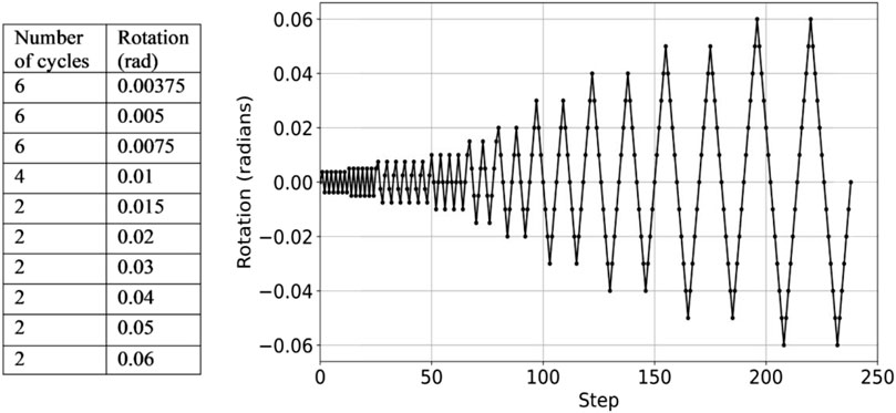
Figure 1. AISC 341 loading protocol (AISC 341-16, 2016).
Particularly, the following characteristic ordinates are of interest. (i) Effective yielding, which corresponds to the onset of appreciable structural damage leading to non-reversible deformation. In the AISC guideline (AISC 341-16, 2016), it is the ordinate of the moment-rotation backbone hysteresis curve where the specified yielding moment of the connection is reached. (ii) Maximum moment capacity, corresponding to the largest moment recorded during the imposed cyclic drift demands up to the maximum applied drift, 6% (at which the analyses stop). (iii) The ultimate moment, namely, the moment and drift ordinates for which vertical load carrying capacity is compromised, or moment decreases by 20% from the maximum moment capacity. An outline of the backbone curve, i.e., the envelope of the typical hysteretic response of a moment connection is shown in Figure 2.
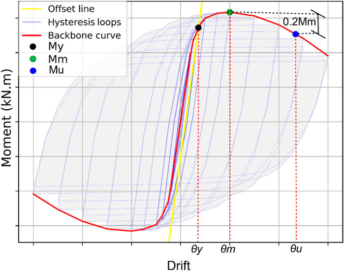
Figure 2. Typical backbone curve for characterising the response of a steel connection, following AISC 341.
A connection within an intermediate moment resisting frame is required to reach a 0.02 ultimate interstorey drift demand, whereas a minimum 0.04 ultimate interstorey drift demand must be attained for deployment within a special moment resisting frame (SMF) (AISC 341-16, 2016).
3 Ductile mechanisms of a welded RWS connection
RWS connections aim at clustering inelastic action by weakening the cross section after making perforations on the beam’s web. Henceforth, capacity design must be enforced to preclude damage elsewhere. The column, the panel zone at the intersection of the beam and column, connecting welds and the vicinity of the column-beam interface are critical locations. The overall geometry of a welded RWS connection with RWS geometry parameters is shown in Figure 3.
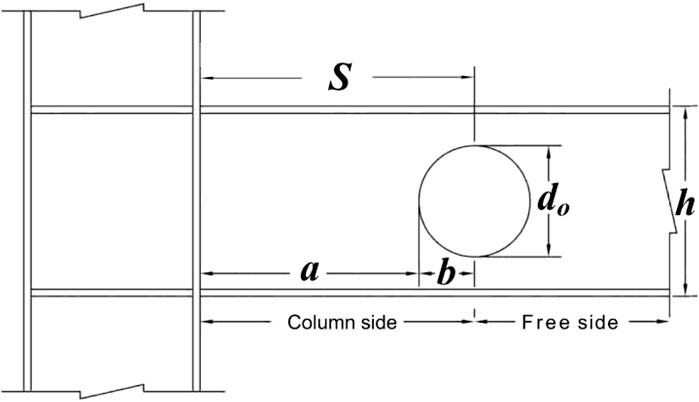
Figure 3. RWS connection geometry.
The first ductile mechanism of an RWS connection is the complete yielding of the reduced cross-section, as shown in Figure 4. The cross-section deforms according to Euler-Bernoulli’s plane section hypothesis, leading to compression at the bottom leg, while tension at the upper one. Hence, moment capacity is given by:
where MP1 is the plastic moment of the reduced cross-section, Z is its plastic modulus, tw is the beam’s web thickness, and fy is the yielding strength of the steel. However, reaching this plastic modulus requires effective transfer of shear across the perforation, (Figure 5), namely:
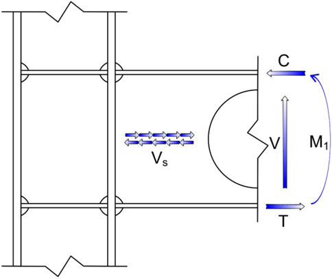
Figure 4. Full plastification of the reduced cross-section.
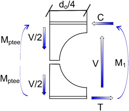
Figure 5. Equilibrium of T stubs.
As moment demands are taken in the middle of the symmetric Tee stubs (Figure 5), V describes the shear at the centre of the perforation. If moment capacities of the tee stubs (MpTee) at the edge of the perforation are less than the value prescribed by Equation 2, the moment capacity will become lower than what corresponds to the full plastification of the reduced cross-section, leading to the Vierendeel mechanism. In this case, capacity will be controlled by yielding the tee stub sections. Nevertheless, yielding of the reduced cross-section and inelastic action on the edges of the perforation are usually concurrent.
Also, it is possible that the Euler-Bernoulli plane hypotheses do not hold for the whole cross-section, leading to strain incompatibility between the sections outside the opening (Figure 6). Namely, both upper and lower tee sections will observe both compressive and tensile strains, as sections of two beams stacked together, having only the same deflections.
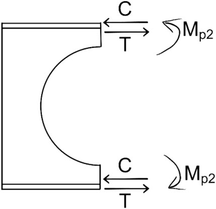
Figure 6. Yielding with relative sliding on both tees of the cross-section.
In this case, moment capacity is given by Equation 3, where ZTeer is the plastic section modulus of each of the tees right over the centre of the perforation.
However, other fragile mechanisms are possible. Being the most critical local flange bucking and web crimpling. The first is a consequence of failure in compression of the upper tee (Figure 3) when subjected to sagging moments. The same phenomenon is observed in the bottom tee when the moment reverses. The second is caused by an insufficient beam web thickness to efficiently transfer shear induced by tension and compression actions across the cross-section, away from the perforation. These undesirable failure modes can be mitigated if Equation 4 holds:
Capacity design can be enforced to ensure that connection elements away from the perforation remain elastic. This is done by performing checks for axial, and shear demands considering increased moments by the overstrength factor that consider strain hardening, provision of stronger-than-expected materials and inelastic load redistribution. The factor by which design moments are increased for performing these checks is called the overstrength factor (FEMA 356, 2000). In this study, factors related to load redistribution will be assessed, by considering the results of detailed FEMs of connection specimens.
4 Methodology
The behaviour of beam-to-column joints can be evaluated with the aid of the component method, largely adopted in research and incorporated into the Eurocode 3 (EC3) (Eurocode 3, 2005). From a theoretical point of view, it can be applied to any connection, provided that the primary sources of strength and deformation are appropriately identified and modelled (Weynand et al., 1996). The component method considers the individual components of the connection, such as the beam, column, end plate, bolts, and welds, and analyses their behaviour and interactions within the whole connection. Breaking down the connection into its constituent parts helps to understand the complex behaviour of connections under various loading conditions, thus easing the formulation of design guidelines (Eurocode 3, 2005). Following the objectives of this study, we deliberately modelled the beam with fixed ends, assuming an infinitely strong panel zone, to strip away the beneficial flexibility of the column and panel zone and thereby isolate the influence of the reduced-web-section (RWS) geometry on cyclic response; this yields a conservative upper-bound on plastic rotations and drift demands.
Other researchers like Mojtabaei et al. (2021) have validated this approach, Phan et al. (2020), Ye et al. (2020), and Horton et al. (2021a), Horton et al. (2021b), Horton et al. (2021c). This ensures that changes in response are due to alterations in RWS geometry, providing clear insights into its behaviour under seismic cyclic loading. Later, where frame-level estimates are required, the additional rotation of the joint components can be superimposed using the EC3 component method (Eurocode 3, 2005), ensuring that the conclusions of our 90-specimen parametric study remain applicable once realistic joint flexibility is reintroduced.
In this study, a numerical framework developed in ABAQUS and Python, which was benchmarked against two experimental studies (Davarpanah et al., 2020a) (Saneei Nia et al., 2013). Then, ninety model assessments were made on a beam fixed (rotation-constrained) on a column. Interstorey drift demands are lower-bound capacity estimates, as column and panel zone deformations are neglected.
Key focus areas include identifying combinations of S and do where yielding is confined to the protected zone around the perforation, thus supporting capacity design. The analysis also defined scaling factors to characterise the connection’s moment capacity relative to the plastification of the reduced cross-section, leading to the formulation of overstrength factors related to load redistribution. The overall methodology is shown in Figure 7.

Figure 7. Flowchart illustrating the methodology used in this study.
4.1 Validation of FE models
This study considered two full-scale sub-assemblies previously investigated experimentally to validate the proposed framework by generating FE models in ABAQUS. Davarpanah et al. (2020a) studied the cyclic behaviour of RWS (HE-RWS) connections with elliptical web openings, while Nia et al. conducted two identical experimental investigations on the Welded Unreinforced Flange-Welded Web connection to box columns under biaxial bending under the name (DC-M-1 and DC-M-2) models (Saneei Nia et al., 2013). The cyclic load applied in both experiments followed the AISC/ANSI 341-16 loading protocol. Details of both experiments are tabulated in Table 1, and further information can be found in Davarpanah et al. (2020a) and Saneei Nia et al. (2013).
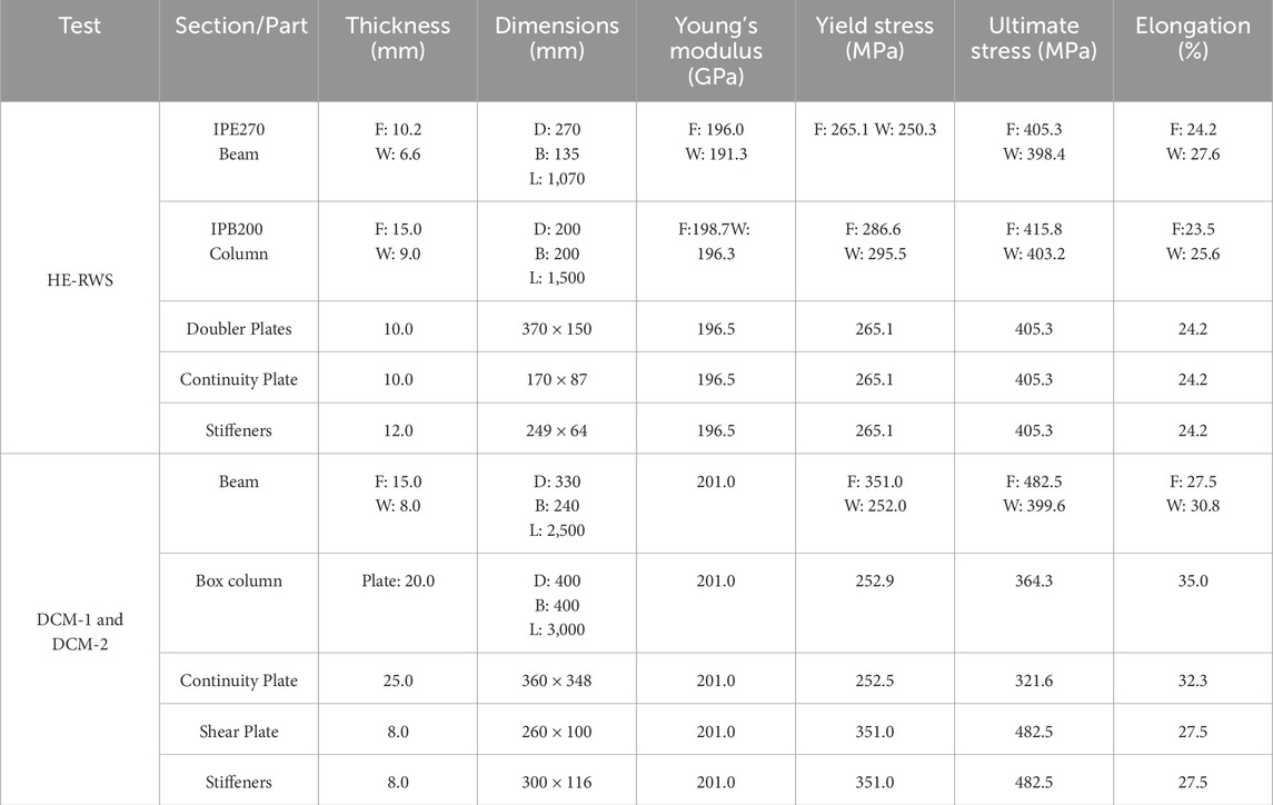
Table 1. Detail of HE-RWS and DC-M connections from experimental tests (F: Flange, W: Web, L: Length, D: Depth, B: Breadth, L: Length) and (ν in all models equals to 0.3).
4.2 Overall properties of the FEM models employed in this study
The steel behaviour is modelled using a trilinear stress-strain curve with combined hardening for all elements. Full 3D nonlinear static analyses were effectuated, using the Newton-Raphson algorithm as the numerical solver within ABAQUS. This approach effectively accounted for nonlinearities arising from large displacements and deformations while neglecting inertial effects on the specimen. Additionally, 4-node reduced integration shell (S4R) elements were employed to enhance computational efficiency and accurately capture local buckling behaviour observed in both the beam web and flanges. Out-of-plane displacements are restricted by providing lateral support at boundaries. Sensitivity studies of the configuration and the density of the FE mesh size led to an optimal element size of 15 mm. The welding line was not explicitly modelled in the FEM sub-assemblies, and instead, tie constraints were used to model the welds. This is a reasonable modelling assumption, as the capacity design of these welds will ensure their elastic response. This is a widely accepted assumption in practice and research (Davarpanah et al., 2020a; Horton et al., 2021c; Horton, 2021). Also, global buckling of the girder is prevented due to bracing provided by beams.
4.3 Benchmarking with HE-RWS connection by Davarpanah et al.
The specimen is an RWS connection with a horizontal elliptical opening in the beam web (HE-RWS) (Davarpanah et al., 2020a). An IPE270 was used for the girder and an IPB200 for the column. Connection details, such as the doubler plate, continuity plate dimension, and weld properties, followed the tested prototype. The connection sections were made of grade ST37 Iranian steel (similar to S235 in the European standard). The modelling approach was initially benchmarked by simulating the experimental study by Davarpanah and his collaborators, as shown in Figure 8.
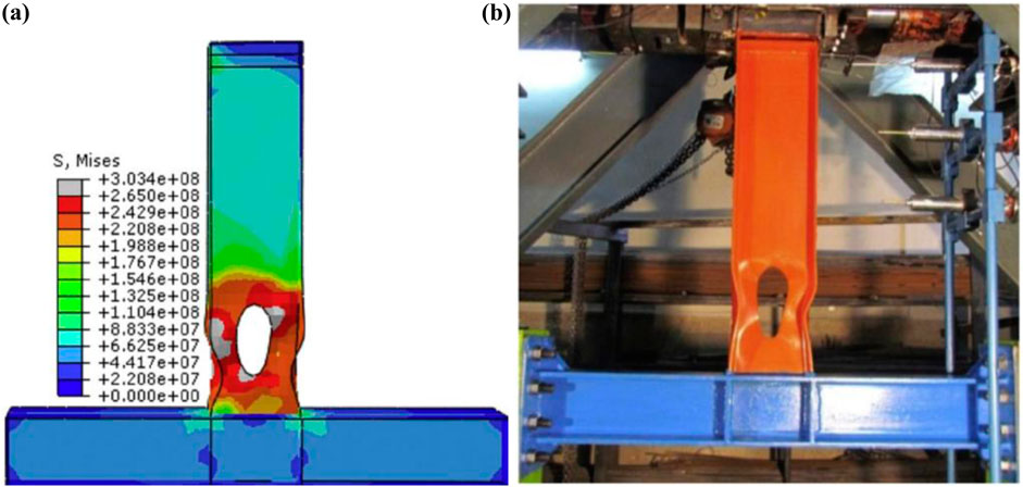
Figure 8. Distribution of Von Mises stress and Local buckling of the flange in the FE: (a) HE-RWS Von Mises stress (b) HE-RWS after testing.
Figure 9 compares the outcomes (hysteresis curves) of the modelling scheme proposed in this study with the experimental results of Davarpanah’s study (FEM curve plotted directly on top of the experimental curve from the literature). There is an acceptable agreement between the current FEM results compared to the experimental and FEM results in the mentioned study.
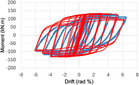
Figure 9. Comparison of the current FEM (in red) with the experimental study (in blue) by Davarpanah for the HE-RWS connection (Davarpanah et al., 2020a).
4.4 Mesh optimisation
The optimisation of the FE analysis involved comparing results from dense meshes (using 5 mm elements) with sparser meshes (using 15 mm and 20 mm elements). The overall moment-rotation curves were practically similar for both mesh densities, even though the running computing time for the dense meshes was significantly longer. Hence, element sizes between 15 mm and 20 mm were adopted for the parametric analyses. Table 2 presents the tabulated negative and positive maximum moments for benchmarking with Davarpanah’s experimental results and that of FEA.
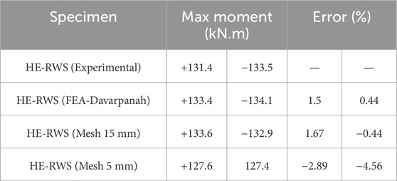
Table 2. Benchmarking with Davarpanah’s experiment and FEA.
It is crucial to highlight that the maximum moment (Mm) value has a low sensitivity to mesh size. However, its corresponding rotation, θm is sensitive. For instance, a change as small as 1 mm in mesh size can alter the value of θm. This sensitivity arises from the fact that the peak moment typically occurs during the larger cycles of the loading protocol while interstorey drift demands were already large. Such sensitivity is important when determining the peak points to define yield points using the idealised force-deformation method recommended in FEMA 356 (FEMA 356, 2000). Nevertheless, this issue was critical only when comparing the outcomes of the 20 mm and 15 mm element-size meshes, while becoming negligible as the results of the 5 mm element-size mesh were benchmarked against the 15 mm one. Henceforth, this element size was adopted hereinafter.
4.5 Benchmarking with DC-M connection by Nia et al.
To provide further reassurance, a second benchmarking assessment was carried out. This time, testing on a welded, unreinforced web connection to a box column (WUF-W) was considered (Saneei Nia et al., 2013). The connection, which included shear tabs and continuity plates, was intended to represent a medium-sized multi-storey exterior connection. The tie command is used to model all welds. Kinematic coupling to a reference point simulated the load point and fixed column end arrangements. Further details of the connection and the experimental setup can be found in the literature (Saneei Nia et al., 2013).
The buckling of the flanges at a 6% drift is shown in Figure 10. Outcomes of the finite element model considered in this study can replicate the observed failure mode.
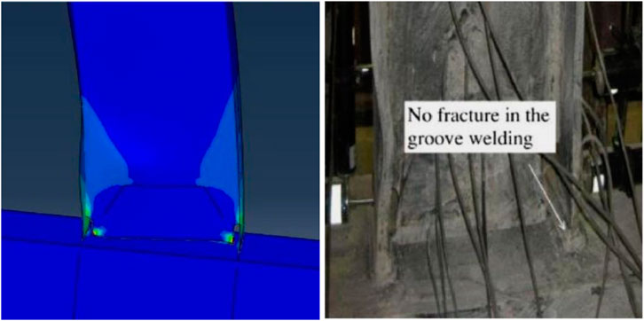
Figure 10. DC-M deformation of FE model ((PEEQ) contour plot) and experimental study, both at 6% drift.
In addition, Figure 11 compares the obtained hysteresis curves using the modelling approach of this study, with the results of the experiments and FEAs provided in (Saneei Nia et al., 2013). The black solid curve is the outcome of this study’s simulation. The blue and red curves represent the measured total forces (kN) at the tip of the beams and the rotations observed during the identical experiments conducted by Saneei Nia et al. (2013).
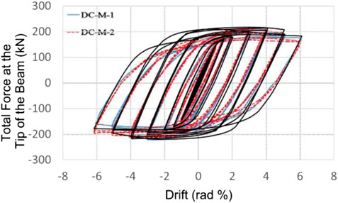
Figure 11. Comparisons of the current FEM result (in black) with those from two identical experiments conducted by Nia et al. for DC-M models (Saneei Nia et al., 2013).
Figure 11 indicates an appropriate fit between the results, verifying the current FE model’s ability to predict the strength degradation by local buckling in the plastic hinge region. Ultimately, the FEM developed in this study employs a single Python script in ABAQUS capable of accurately representing the moment-rotation hysteretic curves for two entirely different experiments with varying properties and geometries.
5 Parametric analysis
After FEM validation, the material properties of HE-RWS presented in Table 1 are selected for parametric studies. A parametric study of 90 specimens with fixed beams with isolated web openings was carried out. The models are IPE270 beams with web opening geometry parameters, as shown in Figure 3, ranging from 0.30 h to 0.75 h, along with nine S variations spanning 0.40 h–2 h for each beam. These specifications are reasonable for low-rise buildings, considering bay widths ranging between 3.5 m and 4 m, leading to span/height ratios between 12 and 15. Supplementary Table A1 shows the beam properties and RWS parameters used in FEA, while Figure the table illustrates the PEEQ and corresponding Von Mises for all cases. Key outcomes from this parametric study include the characterisation of backbone curves, computation of PEEQ and Von Mises strains, yield, peak and ultimate moments discussed in Section 2, besides determining which combinations of S and do result in yielding only in the protected zone.
The equivalent plastic strain index (PEEQ) is one of the most effective parameters for determining the likeness of the connection assembly being brittle or ductile and has been used by researchers as a criterion of plastic strain demand (Chen et al., 2006; Lu et al., 2000). Thus, this index is considered a scale for measuring the local inelastic strain demand (El-Tawil et al., 1999). The PEEQ index values are used to determine the location of the plastic hinge under cyclic loading conditions (Naseri, 2024). An increase in the PEEQ index for a specific location indicates a higher possibility of cracking, damage, or deformation occurring in that region (Naseri, 2024). In addition, another study showed that high PEEQ values indicate a high likelihood of fracture due to tearing at a relatively low drift angle (Davarpanah et al., 2020b). Complimentarily, FEMA 350 has highlighted that when the plastic hinge forms in the beam at the face of the column, this can result in large inelastic strain demands on the weld metal and surrounding heat-affected zones. These conditions can lead to brittle failure (FEMA 350, 2001). Hence, the PEEQ distributions are also considered to evaluate whether inelasticity initiates into the beam web within the designated protected zone away from the column face; therefore, protecting welds and fragile components from inelastic action. It is expected that providing appropriate combinations of S and do should lead to low inelastic action at the beam-column interface, hence attaining low PEEQ values there.
All models consider a fixed beam (encastré) at the column face, thereby all six degrees of freedom are restrained. While, cyclic drift demands are applied at the inflection point of the beam in both Scenarios, in accordance with AISC 341 (AISC 341-16, 2016). In detail, it is applied 35 mm from the top of the beam. The imposed drift time history is taken up to two cycles of 0.06 rad with increments of 0.01 rad, as shown in Figure 1. It must be highlighted that drift capacity outcomes are lower-bound estimates as they neglect column and joint deformations. Capacity design of these elements can be calculated once overstrength factors have been computed for the fixed-on-the-column paradigm being considered. Once capacity design is enforced, plastic behaviour will be confined to protected zones, namely, the vicinity of the perforations, hence keeping elastic behaviour on columns and joints. Likewise, initial imperfections are a secondary concern for this study as the emphasis is made on low-rise buildings with welded hot-rolled short span beams, which have relatively stocky beams and columns. The archetypal model is shown in Figure 12. Supplementary Figure A4 illustrates an example of the displacement time history, developed in accordance with the AISC 341 loading protocol (AISC 341-16, 2016), that is shown in Figure 1 and applied to the subassembly depicted in Figure 12.
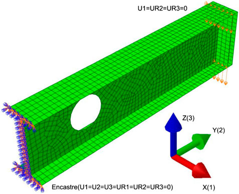
Figure 12. Typical FEM model considered in the parametric analyses.
5.1 Yield moment
The effective yield moment was initially estimated considering Equations 1, 2. However, it was found that for most cases (56%), the maximum moment capacity does not exceed the theoretical plastification moment, regardless of the fact that stable hysteresis loops were obtained, and plasticity was constrained around the perforation. Hence, achieving acceptable behaviour considering capacity design principles. The reason for this outcome is an early development of the Vierendeel mechanism on the edges of the perforation, that limited extensive plastic action at the reduced cross-section. It must be stressed that 75% of compliant specimens showcased a maximum moment larger than 90% of the effective yielding moment, making results reliable.
Yet, there is a need to adopt a better definition of the effective yield moment as a significant share of capacity design-compliant cross sections will not achieve it. After reviewing diverse options, the most efficient alternative was taking an offset of 0.2% radians of the slope of the moment/rotation curve (i.e., the elastic moment/rotation stiffness). Then, the yield moment was defined at the intersection of the offset and the hysteresis curves, as shown in Figure 13.
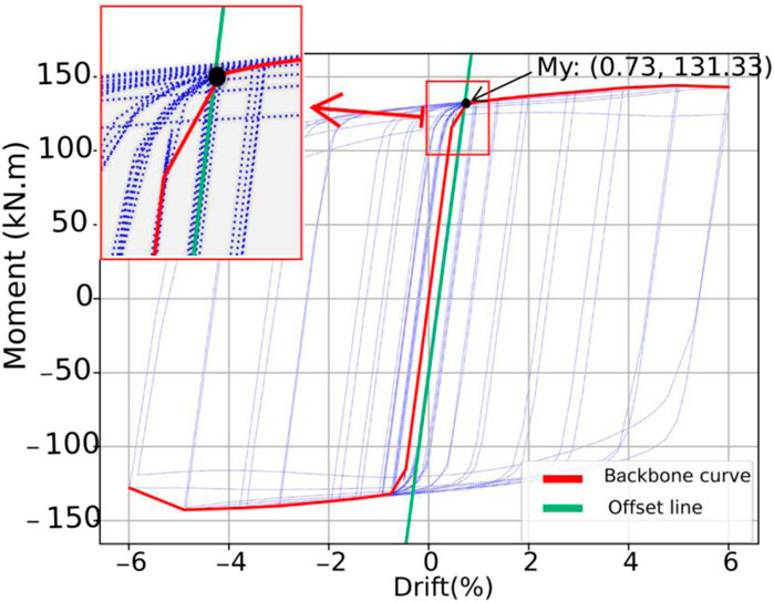
Figure 13. 0.2% drift offset approach for definition of the effective yield moment.
As it is demonstrated (in Supplementary Appendix B) the 0.2% drift offset method leads to a stiffness degradation of less than 20% at the effective yield, akin to the 20% limit on strength degradation for acceptance of the connection (AISC 341-16, 2016). Thereby, this definition was adopted in this study and the effective yield moment My will be defined this way hereinafter.
Figure 14 displays changes in the yield moment My with varying parameters S and do for the 90 combinations. The results evidently showed that S has a mild effect on the yield moment, while do is the dominant parameter. Particularly, there is a reduction in the moment capacity by more than 52% for the case with the largest perforation (75% of the beam height) compared with a solid beam (without perforation).
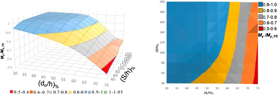
Figure 14. The effect and the interaction of (S and do) on the yield moment reduction (normalised) for 90 circular RWS connections (left figure: 3D view, right figure: Top view).
Also, the effective yield moment does not necessarily match the theoretical plastic moment (Equation 1). This outcome was previously observed in the literature (Boushehri et al., 2019). One of the reasons is that the RWS connections may exhibit different yielding mechanisms depending on S and do as stated in Section 3. Therefore, a least-square nonlinear regression was performed to assess the variability of the yielding moment capacity in terms of the geometrical parameters of the RWS connection. It leads to the following value for the expected value of the ratio of observed effective yield moment and the theoretical plasticisation value:
With a standard deviation of 0.028. Note that negative values are not allowed. However, they are extremely unlikely for reasonable values of do/h and S/h (within 0.35 and 0.75 for the former and 0.5 and 2 for the latter). Equation 5 has an explained variance R2 of 0.86. Lower bound suggested design values (taken at minus one standard deviation) are given in Equation 6:
5.2 Maximum moment capacity and static overstrength
Normalised peak moment values by the capacity of the solid IPE270 beam are shown in Figure 15. In these figures, a reduction of 52% in the moment capacity can be observed between the lower and upper limit values of the parameter do. However, only a reduction of 25% is observed in the peak moment when assessing S solely.
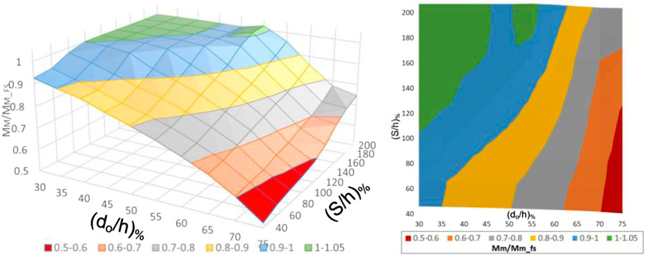
Figure 15. The effect and the interaction of 90 (S and do) combinations on the maximum moment strength reduction (normalised peak moment compared to that of the solid beam).
These trends are explicitly quantified when formulating analytical expressions for the static overstrength factor, namely, the ratio between the yield moment and the maximum observed moment capacity. This parameter is critical for scaling shear and tensile demands for components outside the protected zone, thus ensuring that inelastic action is averted in them. Thus, a least-square nonlinear regression was effectuated to estimate the expected value of the overstrength factor (Equation 7).
While its explained variance R2 is 0.93, negative values are not allowed, yet they are extremely unlikely for reasonable values of do/h and S/h ratios whose limits had been already stated. We recommend adopting an upper bound limit (at one standard deviation away) for design values, as shown in Equation 8:
5.3 Compliance with capacity design principles
Capacity design requires that inelastic action is clustered within designated locations in the beam-column connections, designated as protected zones (AISC 341-16, 2016). For RWS connections, these are over the immediate vicinity of the web perforations. Checking for inelastic behaviour was done by assessing contour plots of Von Mises stresses and Plastic Strain Equivalent. It is observed that large openings (do/h > 0.65) are capable of avoiding inelastic action in the beam-column interface, joint plates, and critical welds. Still, they reduce the moment capacity of the connection significantly (more than 20% following Equation 3). This outcome was observed even for the shortest distance from the column (0.35h). However, other combinations of S and do successfully achieve this outcome with lesser moment reduction capacity. All combinations of do and S parameters that allow for compliance with capacity design principles are outlined in Table 3. An example illustrating how a suitable combination of S and d0 produces the RWS mechanism capable of moving the plastic hinge away from the column face is shown in Supplementary Figure A3.
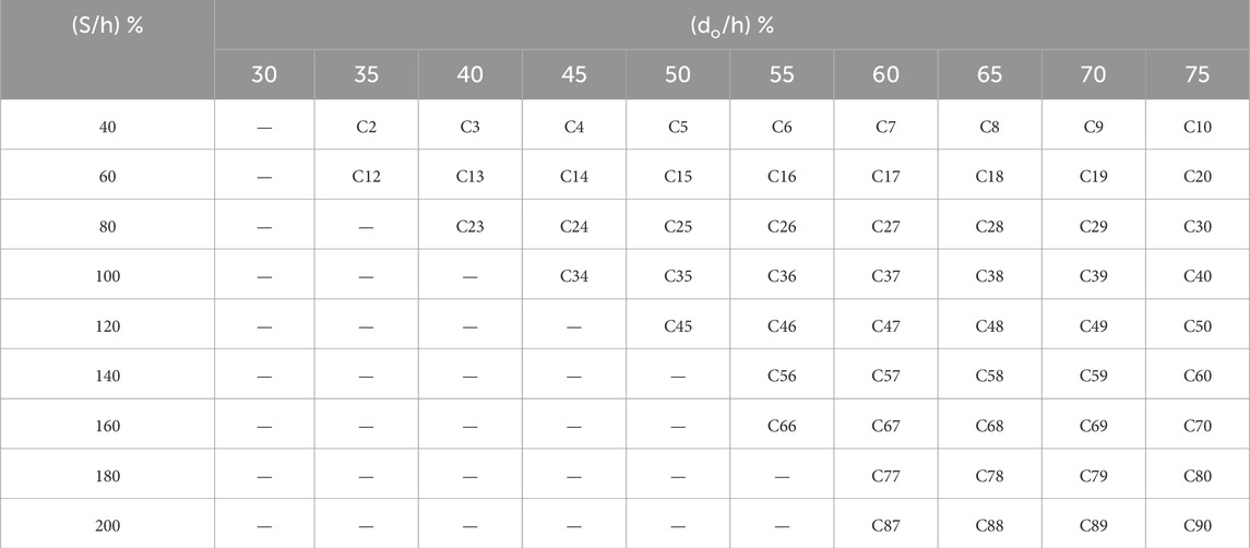
Table 3. Successful combinations of (S and do) resulting in compliant RWS mechanism. (All FE models are listed in Supplementary Table A1 and are shown in Supplementary Figure A1).
Results presented in Table 3 allow for formulation of a criterion for identifying if a particular RWS connection is capable of compliance with capacity design principles. For that purpose, logistic regression was effectuated to estimate the probability of obtaining a stable Vierendeel failure mode around the perforation (and thus ensuring compliance with capacity design). The following expression was found (Figure 16):
where PA is the probability of avoiding yielding outside the protected zone. S/h and do/h ratios must be expressed as percentages. Equations 9, 10 lead to a receiver operating characteristic (ROC) area under the curve of 0.99, thus making them reliable for design. Likewise, the outermost point from the origin of the ROC curve is observed for a median value (50% probability of being exceeded). Hence, this study suggests that taking a PA value larger than the 50th percentile is reasonable for characterising a connection as acceptable for seismic applications. The limit state will be observed for the curve defined in Equation 11:
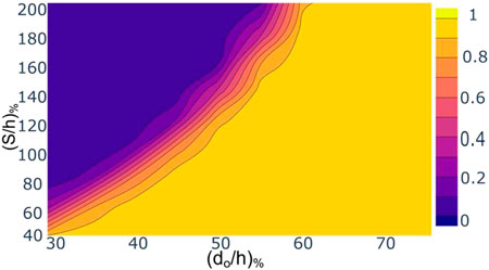
Figure 16. Probability of having yielded solely in the protected zone, for diverse S (abscissa) and do (ordinate).
5.4 Rotation capacity and strength degradation
Results of the parametric assessments indicate that all acceptable specimens following criteria presented in Section 5 showcase a highly ductile behaviour. Peak moment is always larger than 80% of the maximum values for drifts less than 0.04, hence allowing for deployment of connections within Special Moment Frames, per AISC 341 regulations (AISC 341-16, 2016). As shown in Figure 17, this is the case for a large number of web openings and spacings, thus allowing for diverse design alternatives.
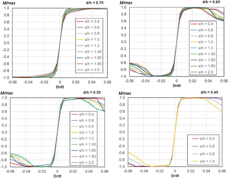
Figure 17. Backbone curves for specimens with do/h = 0.75, 0.65, 0.55, 0.45.
Furthermore, if the ratio S/h is lower than 1.0, strength degradation can be limited to less than 10% for all cases. Even for large openings (do/h ratios) 6% drift demands can be reached with negligible loss of moment capacity. However, this comes with the drawback of a low yield moment. It can be beneficial for cases where beam-column welds are relatively weak, as shear demands can be capped. Moreover, hysteresis cycles of several specimens showcase large area, stable hysteresis loops. Note how there are gentle transitions on stiffness, thus precluding ringing and pinching. Likewise, origin wandering is negligible, indicating that there is no strain accumulation in a particular direction as long drift demands are symmetric. This further supports the fact that inelastic action is clustered within the protected zone.
6 Concluding remarks
This study confirms that Reduced Web Section (RWS) connections are a plausible solution for seismic retrofit of buildings when RWS geometric parameters are chosen appropriately. Detailed parametric finite element model simulations indicate that they are capable of enduring 4% drift demands while showcasing stable hysteresis cycles. Likewise, in all cases assessed where yielding is inhibited outside the protected zone, strength reduction beyond 4% drift demands was less than 20%. This indicates that RWS connections are a ductile solution that can be deployed within special moment frames according to AISC (AISC 341-16, 2016).
Also, appropriate combinations of opening diameters do and web spacings from the column face S that led to plastic actions only in the protected zone (i.e., in the vicinity of the perforation) were found. This led to the formulation of an analytical expression for estimating the probability of yielding avoidance outside the protected zone, for given S and do values (Equation 11). Moreover, design combinations following capacity design principles can be proposed by considering a median (50th percentile) threshold. Likewise, results allowed for the derivation of analytical expressions in terms of do and S to define overstrength factors. They are key to account for increased shear and tensile demands outside the protected zone. It is recommended to adopt one plus standard deviation values for design. Henceforth, an analytical expression is provided for that purpose (Equation 8).
Overall, beams with end distance from the column face to the centreline of the perforation less than one times the beam’s depth, and opening diameter less than half the beam’s depth, can be expected to develop moments more than 80% of the capacity of solid beams, while inelastic stresses developed away from the welding connection zone (within the pre-allocated zone). Additionally, they will be able to sustain more than 85% of the peak moment for drifts larger than 4%. Beams with larger web openings can reach 6% drifts without significant strength degradation. However, effective yielding moments can be significantly lower than the capacity of their unperforated (solid) counterparts when the web opening position is inappropriate as shown in Figure 16. In this case, the capacity reduction can be useful for retrofitting of buildings where shear transfer can be compromised due to the relaxed adoption of sound seismic capacity design principles for elements outside the protected zone. Ratios between nominal and effective yielding are defined by Equation 6.
Consequently, this study hints that use of RWS connection for seismic retrofit is plausible, particularly where shallow fully welded beams are employed in the lateral load resistance systems. Focus was made on one steel beam profile (IPE270), because it allows for testing in moderate-scale facilities; yet it can be deployed in lateral-load resisting frames with bay widths spanning 3 m to 4 m. Moreover, welding to the column was considered instead of bolting. This choice is reasonable as transfer of large tensile and compressive couple actions requires the provision of many bolts that lead to the allocation of large end-plates to accommodate them. Henceforth, it is expected that low-depth, fully welded beams are more prevalent in low-scale dwellings, which in turn can be expected to be less compliant with capacity design principles.
It must be remarked that the outcomes of the study consider low-height buildings with relatively small spans, for which initial imperfections are not expected to be highly relevant, particularly when compared to the effects of overstrength. Moreover, conclusions should be further validated by experimental testing, which is now feasible as overstrength factors can be estimated. In detail, modelling and assessment of effects of initial imperfections should be done considering cruciform specimens where cross-sections of columns and properties of joints are adjusted by overstrength factors, to ensure that inelastic action only occurs on the protected zone (i.e., the vicinity of the perforation).
Data availability statement
The raw data supporting the conclusions of this article will be made available by the authors, without undue reservation.
Author contributions
MB: Data curation, Formal Analysis, Investigation, Software, Visualization, Writing – original draft. KT: Conceptualization, Data curation, Funding acquisition, Investigation, Methodology, Resources, Validation, Writing – review and editing. AA-R: Investigation, Methodology, Supervision, Validation, Visualization, Writing – review and editing.
Funding
The author(s) declare that no financial support was received for the research and/or publication of this article.
Conflict of interest
The authors declare that the research was conducted in the absence of any commercial or financial relationships that could be construed as a potential conflict of interest.
The author(s) declared that they were an editorial board member of Frontiers, at the time of submission. This had no impact on the peer review process and the final decision.
Generative AI statement
The author(s) declare that no Generative AI was used in the creation of this manuscript.
Publisher’s note
All claims expressed in this article are solely those of the authors and do not necessarily represent those of their affiliated organizations, or those of the publisher, the editors and the reviewers. Any product that may be evaluated in this article, or claim that may be made by its manufacturer, is not guaranteed or endorsed by the publisher.
Supplementary material
The Supplementary Material for this article can be found online at: https://www.frontiersin.org/articles/10.3389/fbuil.2025.1592665/full#supplementary-material
References
AISC 341-16 (2016). Seismic provisions for structural steel buildings. American Institute of Steel Construction.
Alba-Rodríguez, M. D., Martínez-Rocamora, A., González-Vallejo, P., Ferreira-Sánchez, A., and Marrero, M. (2017). Building rehabilitation versus demolition and new construction: economic and environmental assessment. Environ. Impact Assess. Rev. 66, 115–126. doi:10.1016/j.eiar.2017.06.002
Aschheim, M. A. (2000). Moment-Resistant structure, sustainer and method of resisting episodic loads. Available online at: https://patents.google.com/patent/US6012256A/en.
Boushehri, K., Tsavdaridis, K. D., and Cai, G. (2019). Seismic behaviour of RWS moment connections to deep columns with European sections. J. Constr. Steel Res. 161, 416–435. doi:10.1016/j.jcsr.2019.07.009
Chen, C.-C., Lin, C.-C., and Lin, C.-H. (2006). Ductile moment connections used in steel column-tree moment-resisting frames. J. Constr. Steel Res. 62 (8), 793–801. doi:10.1016/j.jcsr.2005.11.012
Davarpanah, M., Ronagh, H., Memarzadeh, P., and Behnamfar, F. (2020a). Cyclic behavior of welded elliptical-shaped RWS moment frame. J. Constr. Steel Res. 175, 106319. doi:10.1016/j.jcsr.2020.106319
Davarpanah, M., Ronagh, H., Memarzadeh, P., and Behnamfar, F. (2020b). Cyclic behaviour of elliptical-shaped reduced web section connection. Structures 24, 955–973. doi:10.1016/j.istruc.2020.02.016
El-Tawil, S., Vidarsson, E., Mikesell, T., and Kunnath, S. K. (1999). Inelastic behavior and design of steel panel zones. Journal of Structural Engineering 125 (2). doi:10.1061/(ASCE)0733-9445(1999)125:2(183)
Fares, S. S., Coulson, J., and Dinehart, D. W. (2017). Castellated and cellular beam design. Available online at: https://www.aisc.org/Design-Guide-31-Castellated-and-Cellular-Beam-Design.
FEMA 350 (2001). Seismic design criteria for new steel moment frame buildings. Available online at: https://ascelibrary.org/doi/abs/10.1061/40558%282001%29149.
FEMA 356 (2000). Prestandard and commentary for the seismic rehabilitation of buildings. Washington, DC, USA: Federal Emergency Management Agency. Available online at: https://www.nehrp.gov/pdf/fema356.pdf.
Horton, T. (2021). Predicting reduced beam section (RBS) connection performance in steel moment frames. Available online at: https://etheses.whiterose.ac.uk/29369/.
Horton, T. A., Hajirasouliha, I., Davison, B., and Ozdemir, Z. (2021a). More efficient design of reduced beam sections (RBS) for maximum seismic performance. J. Constr. Steel Res. 183, 106728. doi:10.1016/j.jcsr.2021.106728
Horton, T. A., Hajirasouliha, I., Davison, B., and Ozdemir, Z. (2021b). Accurate prediction of cyclic hysteresis behaviour of RBS connections using Deep Learning Neural Networks. Eng. Struct. 247, 113156. doi:10.1016/j.engstruct.2021.113156
Horton, T. A., Hajirasouliha, I., Davison, B., Ozdemir, Z., and Abuzayed, I. (2021c). Development of more accurate cyclic hysteretic models to represent RBS connections. Eng. Struct. 245, 112899. doi:10.1016/j.engstruct.2021.112899
Lawson, M., and Hicks, S. J. (2011). Design of composite beams with large web openings, P355. Sci Publication. Available online at: https://www.amazon.com/Design-Composite-Beams-Large-Openings/dp/1859421970.
Lu, L.-W., Ricles, J. M., Mao, C., and Fisher, J. W. (2000). Critical issues in achieving ductile behaviour of welded moment connections. J. Constr. Steel Res. 55 (1–3), 325–341. doi:10.1016/S0143-974X(99)00092-9
Mojtabaei, S. M., Becque, J., and Hajirasouliha, I. (2021). Behavior and design of cold-formed steel bolted connections subjected to combined actions. J. Struct. Eng. 147 (4), 04021013. doi:10.1061/(ASCE)ST.1943-541X.0002966
Momenzadeh, S., Kazemi, M. T., and Asl, M. H. (2017). Seismic performance of reduced web section moment connections. Int. J. Steel Struct. 17 (2), 413–425. doi:10.1007/s13296-017-6004-x
Moslehi Tabar, A., Alonso-Rodriguez, A., and Tsavdaridis, K. D. (2022). Building retrofit with reduced web (RWS) and beam (RBS) section limited-ductility connections. J. Constr. Steel Res. 197, 107459. doi:10.1016/j.jcsr.2022.107459
Naseri, R. (2024). Numerical assessment of the RBS connection reinforced with stiffeners’, jun. 27. Review. doi:10.21203/rs.3.rs-4562032/v1
Naughton, D. T., Tsavdaridis, K. D., Maraveas, C., and Nicolaou, A. (2017). Pushover analysis of steel seismic resistant frames with reduced web section and reduced beam section connections. Front. Built Environ. 3, 59. doi:10.3389/fbuil.2017.00059
Phan, D. T., Mojtabaei, S. M., Hajirasouliha, I., Lau, T. L., and Lim, J. B. P. (2020). Design and optimization of cold-formed steel sections in bolted moment connections considering bimoment. J. Struct. Eng. 146 (8), 04020153. doi:10.1061/(ASCE)ST.1943-541X.0002715
Saneei Nia, Z., Ghassemieh, M., and Mazroi, A. (2013). WUF-W connection performance to box column subjected to uniaxial and biaxial loading. J. Constr. Steel Res. 88, 90–108. doi:10.1016/j.jcsr.2013.04.008
Shin, M., Kim, S.-P., Halterman, A., and Aschheim, M. (2017). Seismic toughness and failure mechanisms of reduced web-section beams: phase 2 tests. Eng. Struct. 141, 607–623. doi:10.1016/j.engstruct.2017.03.046
Tsavdaridis, K. D., Lau, C. K., and Alonso-Rodríguez, A. (2021). Experimental behaviour of non-seismical RWS connections with perforated beams under cyclic actions. J. Constr. Steel Res. 183, 106756. doi:10.1016/j.jcsr.2021.106756
Tsavdaridis, K. D., and Papadopoulos, T. (2022). Assessment of beam-column connections using perforated beams with multiple closely spaced web openings. JCSR. doi:10.31224/2258
Tsavdaridis, K. D., and Papadopoulos, T. (2016). A FE parametric study of RWS beam-to-column bolted connections with cellular beams. J. Constr. Steel Res. 116, 92–113. doi:10.1016/j.jcsr.2015.08.046
Uang, C.-M., and Bruneau, M. (2018). State of the art review on seismic design of steel structures. J. Struct. Eng. 144 (4), 03118002. doi:10.1061/(ASCE)ST.1943-541X.0001973
Vesmawala, G., and Mehta, R. (2024). Analysis of steel beam column connection under cyclic loading with reduced web opening type fuses. Asian J. Civ. Eng. 25 (3), 2587–2597. doi:10.1007/s42107-023-00930-9
Weynand, K., Jaspart, J.-P., and Steenhuis, M. (1996). “The stiffness model of revised annex j of eurocode 3,” in Connections in steel structures III (Elsevier), 441–452. doi:10.1016/B978-008042821-5/50100-0
World Steel Association (2023). Sustainability performance of the steel industry 2004-2022. Available online at: https://worldsteel.org/steel-topics/sustainability/sustainability-indicators-2023-report/.
Keywords: seismic retrofit, reduced web section (RWS), seismic steel design, special moment frames, overstrength of RWS connections
Citation: Bayat M, Tsavdaridis KD and Alonso-Rodriguez A (2025) A case study for optimising the geometry and moment capacity of code compliant welded RWS connections. Front. Built Environ. 11:1592665. doi: 10.3389/fbuil.2025.1592665
Received: 12 March 2025; Accepted: 15 May 2025;
Published: 03 June 2025.
Edited by:
Izuru Takewaki, Kyoto Arts and Crafts University, JapanReviewed by:
Hiroki Akehashi, Takenaka Corporation, JapanSimone Ravasini, University of Parma, Italy
Copyright © 2025 Bayat, Tsavdaridis and Alonso-Rodriguez. This is an open-access article distributed under the terms of the Creative Commons Attribution License (CC BY). The use, distribution or reproduction in other forums is permitted, provided the original author(s) and the copyright owner(s) are credited and that the original publication in this journal is cited, in accordance with accepted academic practice. No use, distribution or reproduction is permitted which does not comply with these terms.
*Correspondence: Konstantinos Daniel Tsavdaridis, a29uc3RhbnRpbm9zLnRzYXZkYXJpZGlzQGNpdHlzdGdlb3JnZXMuYWMudWs=