 Yihai Zhang1,2
 Haitao Ma
- 1China Academy of Safety and Technology, Beijing, China
- 2Gathay Safety Technology Co, Ltd., Beijing, China
- 3Zijinshan Gold and Copper Mine, Zijin Mining Group Company Limited, Longyan, China
Groundwater seepage has a significant impact on the stability of the slope of the waste dumping site. In order to explore the instability characteristics of the waste dumping site of Zijinshan Gold and Copper Mine under the action of groundwater seepage, this paper uses physical and mechanical property testing, theoretical analysis of groundwater seepage field, and numerical simulation methods to explore and analyze. The results show that: (1) the internal structure of the rock and soil foundation soil of Zijinshan Gold and Copper Mine waste dumping site softens under seepage, the permeability increases, the pore water pressure increases, the friction between particles decreases, the mechanical strength decays significantly, and the strain softening characteristics are obvious. (2) Under the condition of no seepage, the maximum sliding amount of the slope of the waste dump is 7.82 m, and under seepage, the maximum sliding amount is 10.23 m. The development of cracks on the slope of the waste dump is mainly concentrated within 15 m of the slope surface, and they develop and penetrate upwards at an angle of about 45° at the bottom of the slope, forming a relatively complete sliding surface. The sliding surface is approximately “C” shaped, and the instability radiation range and degree are more obvious. Under seepage, the total number of cracks inside the slope increased by 68.29% compared to without seepage. (3) The seepage effect destroys the structural stability of the slope of the waste dump, and the peak of seepage pressure appears at the bottom corner of the slope. When the internal structural planes of the slope weaken and cannot resist the shear stress generated by external forces, the slope of the waste dump experiences sliding instability. (4) The minimum safety factor of the slope of the waste dump in the research area under groundwater seepage conditions is 1.031∼1.104, and the slope of the waste dump is prone to slip. The proposed “anchor net + grouting” anti-seepage and anti-skid scheme has a good control effect on the stability of the waste dump slope under seepage.
1 Introduction
The stability of open-pit mine slopes is influenced by both intrinsic and extrinsic factors. Intrinsic factors encompass the properties of the rock and soil masses composing the slope, geological structures, rock mass structure, and geostresses, which generally play a decisive role in slope stability. Extrinsic factors include the impact of surface water and groundwater, seismic activity, weathering processes, human-induced excavation, blasting operations, and engineering loads. Among these, surface water and groundwater dynamics are the most significant and active external factors affecting slope stability.
Liu et al. (2024) proposed that using inclined drainage holes can effectively lower the groundwater level, reduce slope seepage, and improve slope stability. Qu. et al. (2024) pointed out that excessive hydraulic pressure causes vertical cracks to open, increases rock deformation, and ultimately leads to slope failure. Wei et al. (2023) believe that the stability of slopes gradually decreases due to mining and groundwater seepage, and the overall stability coefficient of slopes decreases by 1.34% under groundwater conditions. Dou et al. (2023) believed that the safety factor of slopes is negatively correlated with the duration and intensity of rainfall, and tends to flatten out with the continuous rainfall. Moreover, the gradually increasing type has the greatest impact on slope stability. Miao and Ma (2023) believed that as the groundwater level continues to rise, the pore water pressure near the surface diffuses and arranges in a circular arc shape. The pore water pressure value in the middle is the highest, and the corresponding static water pressure inside the slope decreases, while the effect of dynamic water pressure increases. After reshaping the model of seepage density, Guo et al. (2023) redistributed the pore water pressure at the top of the slope, increased the range of negative pore water pressure distribution, and made the transition area more uniform, effectively alleviating the local water accumulation phenomenon in the upper rock layers of the slope caused by the difference in permeability coefficients of different rock layers. Yu et al. (2022b) established the relationship between the macroscopic mechanical properties and microporous mechanical properties of soft rock, and simulated the influence of microcracks and pore development on the stability of soft rock slopes. Chen (2021) analyzed the seepage characteristics and mechanisms of geotechnical excavation slopes, established seepage fields from two aspects: crack seepage and pore seepage, and analyzed the influence and interaction relationship between seepage fields and slope stress fields. Crosta and Prisco (1999) discussed issues related to the hydraulic and mechanical description of local water flow in unsaturated soils, three-dimensional conditions for failure mechanisms, and liquefaction phenomena. Han et al. (2023) used VG function and Gardner function to describe the soil water characteristic curve and permeability coefficient curve, respectively, and derived analytical solutions for rainfall infiltration using traveling wave reduction and series expansion methods.
Yu et al. (2022a) conducted indoor rainfall model experiments on loess slopes to study the influence of interfaces on the seepage characteristics and deformation failure of loess fill slopes, and revealed the failure mechanism of fill slopes under the influence of interface seepage. Yan et al. (2022) constructed a four-dimensional sliding model and stability calculation formula for fracture water pressure, seepage dynamic water pressure, uplift pressure, and rock mass weakening when encountering water under seepage action, and analyzed the stability variation law of near horizontal sliding seepage slopes. Sun et al. (2021) analyzed the formation reasons of water resistance mechanism in internal waste disposal sites using the variation laws of porosity and permeability coefficient of waste disposal materials. Based on soil mechanics knowledge, equivalent substitutes were made for the permeability coefficient in the vertical and parallel bedding directions of the slope in the internal waste disposal site. Li et al. (2021) pointed out that long-term rainfall causes the groundwater level to rise, the cohesion of slopes to weaken, the shear strength to decrease, and the transient safety factor of slopes to decrease. Chen et al. (2020) proposed a multi field coupled numerical analysis method that comprehensively considers unsaturated seepage, expansion deformation, and strain softening using a strain softening model, FLAC3D secondary development platform, and built-in FISH language. Nian et al. (2020) used a two-dimensional slope as an example and based on a dual medium model, studied the infiltration boundary conditions of pore and fracture domains under different rainfall conditions, as well as the relationship between the two, and derived the equivalent rainfall intensity equation for the fracture domain. Xu et al. (2019) developed a finite element calculation program for rock elastoplastic damage seepage coupling based on distributed iteration method, solved the slope safety factor under multi field coupling, and reproduced the evolution law of the damage field during the progressive failure process of the slope.
This article uses methods such as physical and mechanical property testing, analysis of groundwater seepage field, and numerical calculation of slope instability in the waste dump under seepage to determine the instability characteristics of the slope in the Zijinshan Gold Copper Mine waste dump under groundwater seepage. This lays a theoretical foundation for slope stability control and disaster prevention in the waste dump.
2 Overview and hydrogeological conditions of the research area
2.1 General situation
The waste disposal site is mainly composed of 1 # ditch and 2 # ditch. 1 # ditch is located in the central southern part of the Beikou waste disposal site, and 2 # ditch is located in the northern part of the Beikou waste disposal site. It is a northeast facing valley that extends in a “∼” shape longitudinally and has a “V” shape in cross-section. Its downstream ditch mouth merges with 1 # ditch in Dayan, and the slopes on both sides of the valley have a slope gradient of 20°–60°. The slopes on both sides of the valley are covered by silty clay containing gravel from the Quaternary slope and residual slope deposits. There is a thick soft foundation at the slope corner of the waste disposal site, and the geological conditions at the bottom of the slope are poor.
2.2 Hydrogeological characteristics of waste dump slope
This area is located at the southern end of Donglie Mountain in the southern section of Mount Wuyi, with hilly basin and river valley basin landforms as shown in Figure 1. The climate is subtropical monsoon climate zone, warm and humid and rainy. The natural dynamic type of groundwater is runoff type, with large terrain elevation differences and deep water level burial in the area. Groundwater is mainly composed of runoff and dis-charge. After receiving atmospheric rainfall replenishment during the rainy season, the water level in various places rises unevenly, the hydraulic gradient increases, and the runoff discharge strengthens.
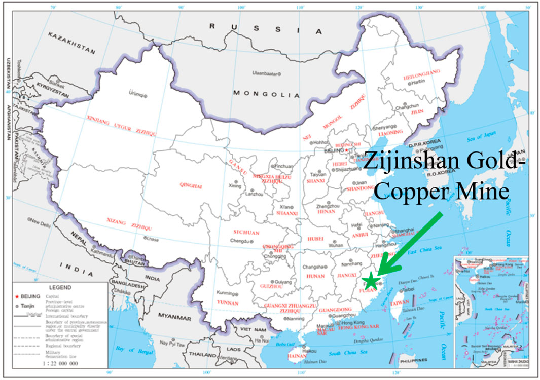
Figure 1. The location where Zijinshan Gold-Copper Mine is situated.
Affected by regional precipitation, the groundwater level in the waste dump has changed significantly. Under the influence of groundwater seepage, the slope has experienced local outward seepage and bottom water accumulation, as shown in Figure 2. Based on past engineering experience and research results, it is known that groundwater has a significant impact on the stability of waste dump slopes, which can easily lead to a decrease in slope bearing capacity and damage to rock integrity, thereby inducing slope instability and even landslide disasters. The slope slip model under seepage action is shown in Figure 3.
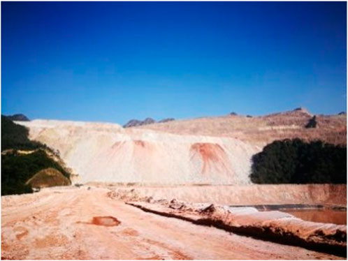
Figure 2. The current situation of the waste dump of Zijinshan Gold Copper Mine.
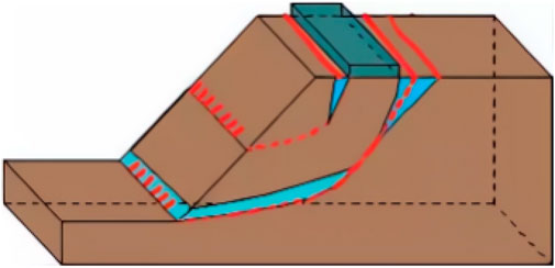
Figure 3. Slope slip model under seepage action.
3 Mechanical characteristics of slope rock and soil under seepage action
Conduct indoor experiments to understand the mechanical properties of rock and soil, determine various physical and mechanical parameters required for numerical model analysis and calculation, and provide reliable basic data for the slope stability analysis of the waste dump. First, collect heap-leached bulk materials and foundation soil from the waste dump slope. Then, sieve the materials multiple times using a sieve to remove large stone fragments. Finally, prepare the samples.
3.1 Particle diameter grading test of rock and soil
Using the sieving method to determine the particle size and composition of the dispersed medium, the maximum sieve size of 80 mm and the minimum sieve size of 0.075 mm were selected for sieving. The particle size test results are shown in Table 1.
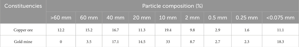
Table 1. Experimental results.
Using the non-uniformity coefficient Cu and curvature coefficient Cc to analyze the grading properties of materials, the larger the Cu, the more significant the difference in the proportion of coarse and fine particles. Soil samples with Cu greater than 5 are called non-uniform soil, while those with Cu greater than 5 are called uniform soil; The curvature coefficient Cc reflects whether the slope of the curve is continuous. When the range of Cc is 1–3, the gradation is continuous. Engineering regulations: Soil with uneven grading (Cu > 5) and discontinuous particle size distribution curve (Cc = 1–3) is called well graded soil. According to formulas (1, 2), the calculation results show that the Cc of gold ore material is 33.3, Cu is 4, copper ore material is 5.33, Cu is 2.5, and the material grading is poor and discontinuous.
where d10, d30 and d60 are the particle sizes corresponding to those whose particle sizes are smaller than 10%, 30% and 60% of the soil particle content, respectively.
3.2 Mechanical properties testing of slope soil under seepage action
The dry density of the gold ore material used in this paper is 2.0 g/cm3 and the porosity is 0.25, and the dry density of the copper ore material is 1.9 g/cm3 and the porosity is 0.27. In the triaxial shear test, a YLSZ30 - 3 large - scale stress - controlled triaxial testing machine is used. The soil from the waste dump slope is wetted and then filled and compacted. The confining pressures are set at three levels: 400 kPa, 600 kPa, and 800 kPa. The initial moisture content of the rock and soil is 20%. During the loading process, drainage is not allowed, and the shear loading rate is 0.03 mm/min until the specimen fails.
The stress-strain curve of the triaxial shear experiment under seepage is shown in Figure 4. In the initial stage of the experiment, there is a nearly linear relationship between stress and strain. At this stage, the sample mainly undergoes elastic deformation. At this time, the initial relative density of the bulk material is low, there are many internal pores, and the mutual contact and friction between particles are relatively weak. Therefore, the applied stress can be easily transmitted, resulting in an increase in strain proportional to the stress, and the material deformation is approximately elastic deformation. When the stress gradually approaches the yield point of the material, the curve begins to deviate from the initial linear relationship. This turning point marks the transition of the material from elastic deformation to plastic deformation. At this point, structural adjustments begin to occur inside the material, and the contact friction between particles significantly increases. The pores are gradually closed or rearranged, and the deformation of the material is no longer reversible. At the moment of approaching failure, although the axial pressure tends to stabilize, the strain rapidly increases, indicating that the material has entered the plastic flow stage, that is, the strength of the bulk material has reached the yield limit. Overall, under the action of seepage, the rock and soil exhibit strain softening characteristics.
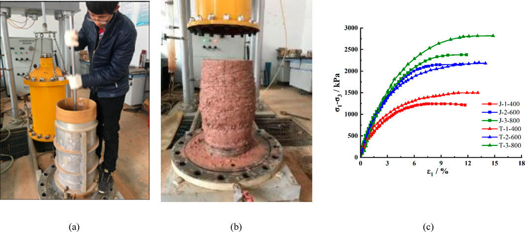
Figure 4. Schematic diagram of triaxial shear test. (a) Compaction in layers according to bulk density. (b) Specimen failure characteristics. (c) Stress-strain curves.
The entire process of triaxial shear test reflects the gradual accumulation and interconnection of micro fractures inside the bulk material, forming a macroscopic failure surface, ultimately leading to the overall failure of the specimen, revealing the boundary of the material’s ability to withstand loads in practical applications. In addition, by analyzing the variation trend of triaxial shear strength under different con-fining pressure conditions, it can be seen that when the experimental confining pressure is 400 kPa, the peak values of deviatoric stress of gold and copper ore materials are 1.24 and 1.50 MPa, respectively. With an increase of 200 kPa in confining pressure, the triaxial shear strength of gold and copper ore materials increases by 74.2% and 46%, respectively. When the confining pressure increases by 400kPa, the triaxial shear strength increases by 91.9% and 88%, respectively. The experimental results indicate that increasing the confining pressure of the rock and soil mass on the slope is beneficial for improving the shear resistance of the slope, thereby enhancing its stability.
3.3 Shear strength testing of rock and soil under different water content states
In the direct shear test, the material was 2.0 g/cm3 and the porosity was 0.25. The direct shear test uses a strain controlled direct shear apparatus in the laboratory, which is mainly composed of a shear box, a vertical pressure device, a shear transmission device, a force gauge, and a displacement measurement system, as shown in Figure 5.
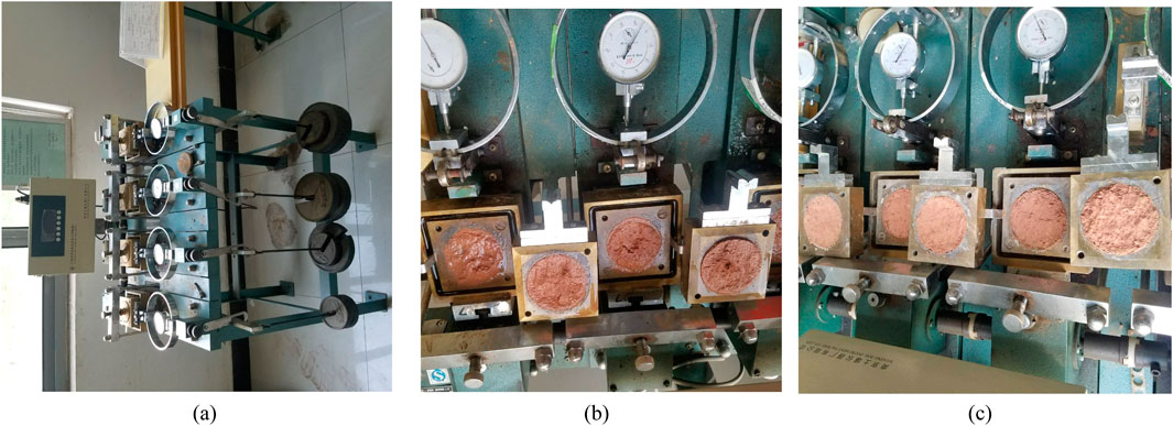
Figure 5. Strain control direct shear instrument and sample failure diagram. (a) Strain control direct shear. (b) Failure characteristics of saturated specimens. (c) Failure characteristics of natural specimens.
In the natural state, the moisture content of the foundation soil is 23%, and in the saturated state, it is 47%. Now, vertical pressures of 100, 200, 300, and 400 kPa are applied to the foundation soil samples in the natural and saturated states respectively. A consolidated undrained test is adopted. The vertical deformation is measured once every hour until the consolidation deformation of the samples becomes stable. The criterion for deformation stability is that the deformation per hour is no more than 0.005 mm. The shear rate in the consolidated quick - shear test is 0.8 mm/min until the samples fail. The experimental results are shown in Table 2.
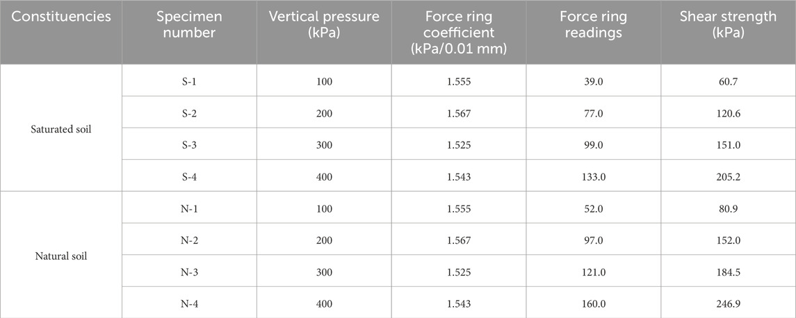
Table 2. Strength parameters of subsoil samples.
According to Table 2, the shear strength of the base soil sample showed varying degrees of attenuation after saturation. Under different vertical pressures (100, 200, 300, 400 kPa), the shear strength of saturated soil samples decreased by 25%, 20.7%, 18.2%, and 16.9% respectively compared to their natural state. The attenuation amplitude of shear strength decreased with the increase of vertical pressure, indicating that water weakens the shear strength of the slope base soil, while vertical pressure enhances its shear strength.
The calculation results of triaxial shear test and consolidation fast shear test are shown in Figure 6. The loose material in the waste dump prepared according to the indoor screening results has a cohesion c value of 25.2 kPa and an internal friction angle φ value of 37.3° in its natural state; The cohesion c value of copper ore material is 41 kPa, and the internal friction force φ value is 38.8°. The mechanical properties of the two materials are similar. The cohesive strength c value of the base soil in the research area in its natural state is 33.4 kPa, and the internal friction angle φ value is 27.9°; The cohesive force c value in the saturated state is 18.4 kPa, and the internal friction angle φ value is 24.9°, indicating that the cohesive force and internal friction angle of the soil sample decrease to a certain extent after immersion. This is mainly due to the softening of the internal structure of the soil sample at saturation, the increase of pore water pressure, and the decrease of inter particle friction force, resulting in a decrease in its strength parameters. The experimental results can lay an experimental foundation for the establishment and verification of numerical models.
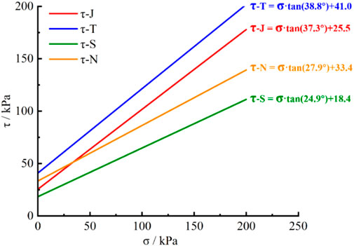
Figure 6. Results of triaxial shear test and consolidation quick shear test.
Based on the above experiments, it can be seen that the loose particles of the soil and rock on the slope of the waste dump are mainly larger, with strong permeability. Under the action of groundwater seepage, clay minerals in the soil and rock are easily transported, resulting in a significant decrease in the strength of the slope. According to the results of mechanical tests, the stress attenuation characteristics of rock and soil under seepage are mainly characterized by strain softening, and the water content state is the main factor affecting this characteristic. Therefore, analyzing the ground-water seepage field is the key to studying the stability of such slopes.
4 Establishment of seepage field model for waste dump slope
Based on the weakening and attenuation of soil and rock under the influence of groundwater seepage in the waste dump, it is necessary to determine the slope seepage field and immersion surface under seepage, and conduct theoretical analysis on the groundwater model and related parameters of the slope in the waste dump of Zijinshan Gold Copper Mine (Jiang et al., 2014; Tang et al., 2013; Tang et al., 2006; Huang et al., 2004; Tan et al., 2003; Qi et al., 2003; Yao et al., 2002).
4.1 Slope seepage calculation model
Determining the position of the seepage free surface is a prerequisite for seepage calculation. The head pressure on the seepage free surface is equal to atmospheric pressure, so the Equation 3 conditions should be fulfilled on the surface without water seepage:
Define a heuristic solution as:
where NN is the total number of nodes in the study area, Ni is the weight function, and Hi is the head value of the corresponding nodes.
Then Equation 4 can be written as
where Ni(ξ,η) (i = 1,…,4) is the shape function, where (ξi, ηi) is the local coordinates of the node i, and the global and local coordinates can be expressed by the shape function as Equation 6:
where xi,zi (i = 1,…4) is the known overall coordinates of the node. According to the concept of isoparametric elements, the seepage equation can be written as:
Substituting Equation 5 into Equation 7 establishes the seepage dominance equation with j = 1,…,4.
Thereinto, the relevant parameters in the equation are as follows Equations 9, 10:
The algebraic Equation 10 of the seepage problem is obtained by assembling the unit seepage Equation 8 as a whole
where [M] is the overall permeability matrix, {H} is the node head array, and {F} is the right end term array.
4.2 Determine the infiltration and exudation surfaces
There are seepage free surface and seepage surface in slope seepage, as shown in Figure 7. If the influence of capillary water, local saturated zone and water evaporation on seepage is not considered, the whole slope can be divided into seepage saturated zone Ω1 and non-seepage zone Ω2.
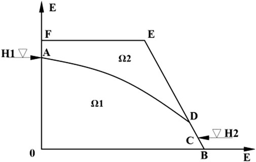
Figure 7. Seepage free surface.
The node virtual flow method is used to deal with this problem. The boundary AD is the free surface of seepage, and the water pressure P = 0. The head of the piezometric tube is equal to the position head H = Z, and there is no flow exchange between the region and Ω2. However, the flow continuity condition of the real node is based on the solution of the virtual flow contribution from the seepage virtual zone Ω2, and there must be overflow phenomenon on the interface AD of the two domains Ω1 and Ω2. In this regard, the basic idea of step-by-step iterative calculation is adopted. On the basis of the previous approximate solution, after deducting the node virtual flow contribution to the left side of the seepage equation, new solution equations set are obtained, as Equations 12, 13:
where n is the total number of virtual nodes, which can be judged according to the condition of H < Z.
A new approximate solution {H} is obtained by solving the system of equations. If each head component satisfies the phenomenon of no flow exchange along the normal direction of any point on the free surface, the solution is obtained. If the maximum ex-change value water is at a given allowable precision, the iterative calculation will be completed, and the approximate solution that meets the engineering accuracy requirements will be obtained.
4.3 Numerical model establishment and parameter calibration
Based on the relevant parameters obtained from the mechanical tests and the above - mentioned idea of flow field analysis, the PFC 2D software was used to establish a numerical calculation model for the slope of Zijinshan Gold - Copper Mine. In this simulation, the cb bonded contact model was adopted, and only the unidirectional seepage effect was considered. Due to the poor particle gradation, spherical particles of the same diameter were used in the model. According to the above formula calculations, the seepage field of the model is formed through the long-term accumulation of mine groundwater. From the toe to the crest of the slope, the seepage surface presents a fan-shaped distribution from the outside to the inside; the pore pressure calculated shows an inclined distribution at a 45-degree angle, and the pressure value gradually increases from top to bottom. The physical and mechanical parameters and the numerical calculation model are shown in Figure 8.
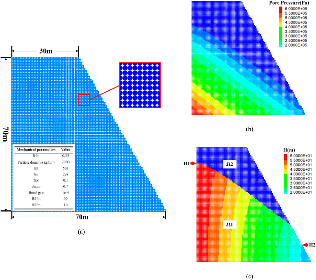
Figure 8. Model construction. (a) Model. (b) Seepage model head distribution. (c) Pore pressure distribution characteristics.
5 Analysis of the instability characteristics of waste dump slopes under seepage action
5.1 Characteristics of displacement changes in the slope of the waste dump
The numerical model operation results are shown in Figure 9, and the experimental results deeply illustrate the significant impact of seepage effects on the stability differences of slopes. Without considering the effect of seepage, as shown in Figure 9a, the slope model showed significant displacement at 2000 steps, with a maximum slip of 0.82 m. At 5,000 steps, the slope model was completely unstable, with a maxi-mum slip of 7.82 m. At this point, the slope exhibited large-scale sliding, and the sliding surface formed a linear distribution at an angle of nearly 45° with the horizontal plane. The instability characteristics of the slope showed regularity, mainly following a single plane sliding pattern.
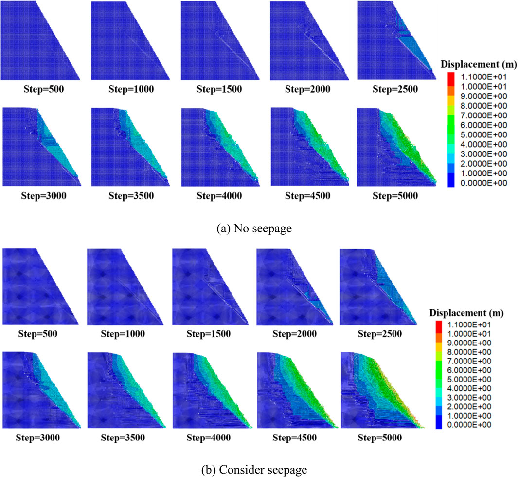
Figure 9. Slope displacement contour: (a) No seepage. (b) Consider seepage.
The displacement of the slope considering the effect of seepage is shown in Figure 9b. When the model runs to 1,500 steps, the maximum displacement of the slope has reached 0.73 m. When the model runs to 5,000 steps, the maximum displacement of the model is 10.23 m, and the sliding surface is approximately “C” - shaped. Compared with the case without considering seepage, the sliding amount and sliding area of the slope have significantly increased. Under unstable conditions, the slope displacement has increased by 30.82%, and the range and degree of instability radiation are more obvious. Comparing the results of two sets of experiments, it can be seen that seepage not only increases the displacement of the slope, but also reconstructs the slip path and mode, resulting in a wider and more complex distribution of unstable areas, significantly enhancing the expansion effect and failure strength of instability.
5.2 Distribution characteristics of cracks on the slope of the waste dump
The distribution characteristics of cracks in the numerical model are shown in Figure 10. When running to 2000 steps, the distribution characteristics of cracks in the model with and without seepage are shown in Figures 10a,b. The number of cracks without seepage is 1823, and the crack development is mainly concentrated on the slope. At the bottom of the slope, it develops and penetrates in a direction of about 45° upwards, forming a relatively complete slip surface. It vigorously develops in the tri-angular area formed perpendicular to the top of the slope and gradually expands to-wards the top of the slope. A small number of cracks are formed inside the slope, and the internal stress of the structure continues to accumulate and release. Under the action of seepage, the development and distribution characteristics of cracks on the slope are basically the same as those under the condition of no seepage. However, there are a certain number of cracks developing and gradually penetrating inside the slope. At this time, the total number of cracks reached 3,068, an increase of 68.29% compared to the condition without seepage.
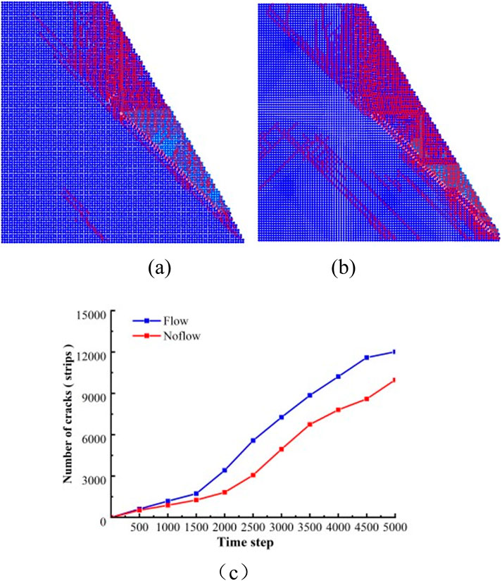
Figure 10. Distribution characteristics of slope cracks. (a) No seepage (Step = 2,000). (b) Consider seepage. (c) Fracture number curve.
The number of cracks generated during the numerical model calculation process is shown in Figure 10c. The number of cracks at 2,000 steps in the no seepage model is similar to 1,722 cracks at 1,500 steps in the seepage model, and the crack development rate begins to increase, with an increase of 211.76% and 120.74%, respectively. This also confirms that the critical points for significant slope sliding under non seepage conditions in Section 4.1 are divided into 1,500 steps and 2,000 steps. When the slope is completely unstable, the total number of cracks in the seepage model is 12,017, which is an increase of 20.47% compared to the total number of cracks without seepage model, which is 9,975. This phenomenon indicates that the seepage of groundwater not only accelerates the expansion of existing cracks, but also promotes the formation of new cracks, especially inside the slope, further reducing the overall stability of the slope.
Based on the degree of crack development and the displacement characteristics of the slope, the process of slope instability can be divided into four stages, as follows:
Initial disturbance stage: During this stage, external disturbances are applied to the slope, causing local stress states to begin to change. Energy accumulates inside the slope, but no obvious cracks have yet formed.
Crack initiation stage: With the accumulation of load or time, the energy accumulated inside the slope is released, and a small number of cracks begin to appear. These cracks indicate that the physical state of the slope rock and soil is beginning to develop towards the plastic failure stage.
Crack penetration stage: With the continuous release of energy accumulated inside the slope, cracks gradually increase and interconnect with each other, especially under the influence of groundwater seepage. This process accelerates and gradually forms a continuous crack network, indicating a significant decrease in slope stability.
Complete instability stage: As the cracks continue to develop and penetrate, the internal structure of the slope is severely damaged, ultimately unable to withstand external loads, resulting in significant sliding or collapse, indicating that the slope has entered a state of complete instability.
5.3 Evolution characteristics of seepage flow in the slope of the waste dump
The distribution characteristics of slope seepage pressure are shown in Figure 11. Under the action of seepage, the slope model runs completely unstable at 5,000 steps. At this time, the slope slip and crack development reach their peak values. At this time, the peak of seepage pressure appears at the bottom corner of the slope. The high seep-age pressure pushes the rock and soil mass of the slope to slide along the slope towards the bottom corner direction, resulting in a sharp increase in overall structural instability. The direction of slope slip is basically consistent with the direction of seepage pressure, and the distribution of seepage pressure shows a layered phenomenon with irregular interfaces, reflecting the nonlinear characteristics of groundwater flow through complex geological structures. There is a certain area along the sliding surface towards the bottom corner of the slope, where the seepage pressure shows a trend of first increasing and then decreasing. This distribution pattern is closely related to the redistribution and local collapse of particle media during the instability process of the slope. With the gradual destruction of the internal structure of the slope, the migration of soil particles and changes in porosity lead to adjustments in the seepage path, which in turn affects the distribution pattern of seepage pressure.
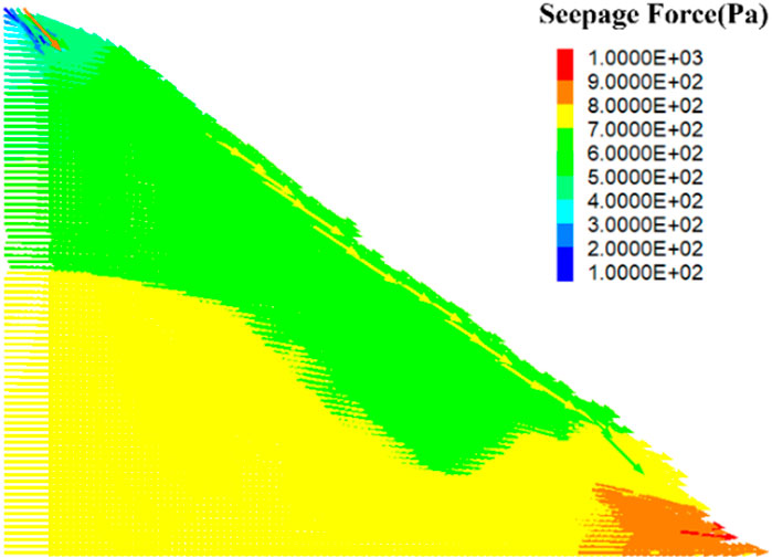
Figure 11. Characteristics of osmotic pressure distribution (Step = 5,000)
The impact of infiltration on the stability of rock and soil is multifaceted and complex, profoundly altering the physical and mechanical properties of the soil and posing a serious threat to slope stability. When groundwater invades the pores and fractures of rock and soil through mechanisms such as capillary action and gravity drive, it not only directly increases the water content of the rock and soil, but more importantly, the water occupies the space originally supported by solid particle contact, resulting in a significant reduction in effective stress between particles. The reduction of this effective stress is like pulling away the supporting force from the skeleton of the rock and soil mass, causing the connections between the rock and soil particles to become relaxed, and the cohesion and cohesion are greatly reduced, thereby weakening the ability of the rock and soil mass to resist external forces. Especially for slope areas, this effect is particularly evident. Under the long-term action of groundwater, the structural planes inside the slope will gradually soften, and the frictional resistance will decrease, resulting in a significant reduction in shear strength. When the shear strength of a key structural plane inside the slope cannot resist the shear stress caused by gravity, water pressure, or other external forces, the structural plane will slide or move, leading to the occurrence of slope instability.
The maximum displacement of the slope model under seepage is 10.23 m, and the slip surface is approximately “C” - shaped. The displacement of the slope has increased by 30.82%, and the range and degree of instability radiation are more obvious. The development of slope cracks is mainly concentrated on the slope, and they develop and penetrate upwards at an angle of about 45° at the bottom of the slope, forming a relatively complete fan-shaped slip surface. Under the action of seepage, a large number of cracks develop and penetrate inside the slope. The peak of seepage pressure occurs at the bottom corner of the slope, and the direction of slope sliding is basically consistent with the direction of seepage pressure. Under the action of seepage, groundwater invades the pores and cracks of the rock and soil mass, and the overall structural stability of the rock and soil mass is destroyed. When the internal structural planes of the slope weaken and cannot resist the shear stress generated by external forces, the slope exhibits sliding instability.
Therefore, for slope areas with groundwater seepage, timely geological exploration, reasonable drainage design, and effective reinforcement measures are crucial. To ensure the long-term stability and safety of the slope, this article conducts slope stability analysis and control method verification based on the above experimental results.
6 Stability analysis and control of slope in waste disposal site
6.1 Analysis method for slope stability of waste dump
Based on the geological conditions and research conclusions of the Zijinshan Gold Copper Mine, the slope stability limit equilibrium method was used for quantitative analysis of slope stability (Chen and Zhu, 2010; Zhao et al., 2003; Chen and Chen, 2001; Huang and Ding, 1999). The calculation accuracy and applicable conditions of the equilibrium analysis method used are shown in Table 3.
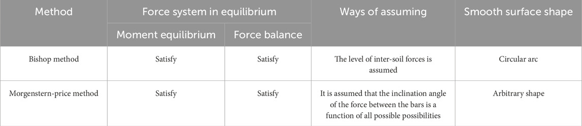
Table 3. Slope stability limit equilibrium method.
6.1.1 Bishop method
The Bishop method is a commonly used stability calculation method for arc-shaped sliding surfaces, and satisfies the equilibrium conditions of all strip forces, and its mechanical mechanism is shown in Figure 12.
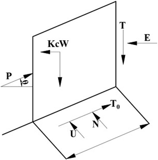
Figure 12. Schematic diagram of Bishop method.
Where E is the horizontal component of the thrust of the upper block; T is the vertical component of the thrust of the upper block; W is the gravity of the bar; Kc is the horizontal seismic force of the block; N is the effective normal stress resultant force at the bottom of the strip; T is the shear force of the sliding surface at the bottom of the strip; U is the resultant force of the water pressure at the bottom of the strip; P is the reaction force of the lower block, and there are three different assumptions about the inclination θ of P. The value range of the three methods of P inclination θ is shown in Table 4.
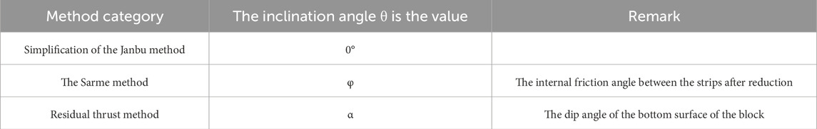
Table 4. The value range of the three methods of P inclination θ
When considering seismic and groundwater interactions, there are calculated as Equations 14, 15:
Ei and Xi represent the normal and tangential interbar forces, Wi is the self-weight of the bar, Kci is the horizontal seismic force, and ci and i are the effective adhesion force and internal friction angle of the material, respectively. φ.
In the above formula, the effect of Xi between each block is unknown, and the safety factor Fs that satisfies the force balance condition of each block can be obtained by iteration. The calculation of the accurate Bishop method is more complicated. Therefore, Bishop proposed the simplified method of assuming Xi = 0. The research shows that the calculation results of the simplified Bishop method and the exact calculation method are very close. Therefore, the simplified Bishop method is the most commonly used method for calculating arc-shaped damage, and the calculation accuracy is also high.
6.1.2 Morgenstern-price method
Morgenstern and Price divided the micro-strips into very small pieces with a width of dx, so that differential equations can be established based on the force balance relationship of the micro-strips. The slope line y = z (x) is known, the sliding surface line y = y (x) is of any shape, not necessarily an arc, and the thrust line is y = h (x). The mechanical equilibrium equation of the force and the position of the force is established in the coordinate system. The calculation principle of the M-P method is shown in Figure 13.
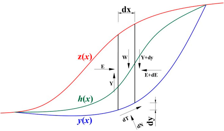
Figure 13. Schematic diagram of the M-P method.
For the moment equilibrium equation at the bottom of the bar and simplified, we get:
The potential slip mass is actually divided into a finite number of slices, and its width dx is trace, but not infinitesimal. In the width dx, the functions h (x), y (x), f (x) and so on can be assumed to be linear functions, which makes it easy to find Ei+1 from E1 in dx. From Equation 16, the torque equation on the side of the strip can also be written as Equation 17:
In this way, EI and MI can be solved one by one, and En = 0 and Mn = 0 must be satisfied. If the continuous iteration is not satisfied, the iterative process is the process of gradually correcting Fs and λ.
The Morgan Stan method requires that the force and moment of each block meet the balance requirements, and it is realized by repeated iteration. Of course, it also meets the overall mechanical balance requirements, so it is a relatively strict slice method. Although it also satisfies the overall moment balance equation, it does not directly use the finishing moment balance equation, and does not use the overall moment balance equation to simplify the calculation. Therefore, it is applicable to any shape of the sliding surface, and it is also a common slice method.
6.2 Stability calculation results under groundwater seepage conditions
According to the Technical Code for Slope Engineering of Non Coal Open pit Mines (GB51016-2014), the safety level classification and basic regulations of slopes are mainly considered in this study, which mainly considers the load type I combined load on the slope of the waste dump of Zijinshan Gold Copper Mine, that is, the load combination type is self-weight + groundwater. Based on the on-site geological conditions and drilling data, two typical profiles in the study area that are severely affected by groundwater seepage were selected. The calculation results of the profile safety factor are shown in Table 5.
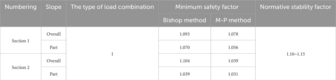
Table 5. Minimum safety factor for profile.
The calculation results of the minimum safety factor for the slopes of two waste dumping sites in Jinshan Copper Mine are shown in Figure 14. Combined with Table 5, the overall and local most dangerous sliding surfaces of the control profile slopes are analyzed. The calculation results of the simplified Bishop method are basically consistent with those of the Morgenstern Price method. The minimum safety factors of the two profiles are 1.078∼1.093 and 1.039∼1.104 as a whole, and 1.056∼1.070 and 1.031∼1.039 locally. According to the calculation results, it can be seen that in the absence of any support and reinforcement measures for the profile, there is a situation where the stability factor of the excavated slope is lower than the safety factor required by the specifications, that is, the slope cannot reach the excavation conditions without reinforcement, and safe construction cannot be carried out. Under the action of groundwater seepage, the minimum safety factor of the slope has decreased to varying degrees, and the stability of the slope has weakened, which may lead to soil erosion or sliding. In the process of slope stability control and disaster prevention, it is necessary to establish smooth drainage facilities and drainage systems to prevent sliding and damage to the surface of the step slope.
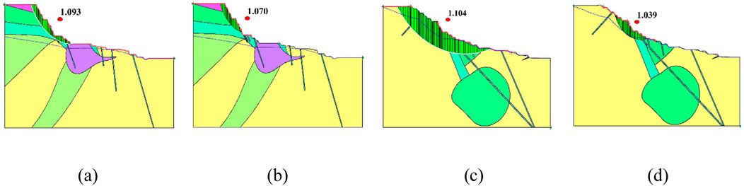
Figure 14. The most dangerous sliding surface of the overall and local slopes of the control profile. (a) Section 1 as a whole. (b) Section 1 partial. (c) Section 2 overall. (d) Section 2 partial.
6.3 Stability control of waste dump slope under seepage action
Based on the numerical simulation experiment results and slope stability calculation results, the degree of slope instability and slip formation law of the Zijinshan Gold Copper Mine waste dump have been clarified. A simplified support model is proposed to compare the control effects of two stability control schemes on slope slip and deter-mine a reasonable control scheme and control technology.
6.3.1 Scheme 1: simplified model and operation results of pile support
Three piles are equally spaced on the slope, the horizontal interval is 10 m, and the pile is driven into the slope depth of 20 m. The numerical simulation results of slope control effect under two different working conditions are shown in Figure 15. It can be seen from the figure that the pile support has achieved certain support effect under the action of seepage or not, and the failure depth and slip degree of the slope have been improved to a certain extent.
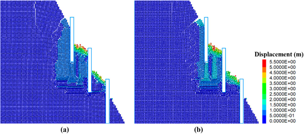
Figure 15. Effect of slope pile support (a) is the case of seepage; (b) is the case without seepage).
The monitoring results of slope control effects under two different working conditions are shown in Figure 16. Under the condition of pile support, when the seepage slope model runs to 5,000 steps, the maximum slip of the slope is 5.43 m, and the total number of cracks developed is 9,375, which is 46.92% less than the maximum slip and 21.99% less than that without support measures; The maximum slip of the non-permeable slope model is 5.26 m, and the total number of developed cracks is 7,173, which is 32.74% and 28.09% lower than that without support measures, respectively. By comparing the monitoring results of slope control effects under two different working conditions, the pile support system can suppress the sliding tendency of the slope to a certain extent, control the adverse effects of groundwater seepage on slope stability, and is one of the effective means to improve slope stability and control potential landslide risks.
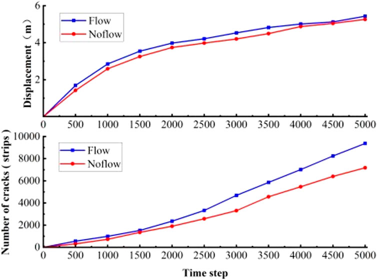
Figure 16. Monitoring of slope pile support effect.
6.3.2 Scheme 2: “anchor net + grouting” support simplified model and operation results
Nine anchor cables are evenly spaced in the vertical direction along the slope, with lengths of 16, 12, and 8 m decreasing from top to bottom. The horizontal spacing between the anchor cables is 4 m, and a certain range of metal mesh is laid on the slope. The grouting effect of the anchor cables is simulated by increasing the overall strength of the rock mass. The numerical model and anchor cable mesh layout are shown in Figure 17. When the model reached 5,000, both the seepage slope model and the no seepage slope model showed significant slope sliding and crack development. According to software monitoring data, the maximum sliding amount of the seepage slope model was 0.076 m, and the maximum sliding amount of the no seepage slope model was 0.073 m. The stability control effect of the slope was very significant. In this scheme, anchor rods provide strong anchoring force, and the laying of metal mesh further enhances the stability of the slope surface, effectively preventing the peeling and small-scale sliding of the surface soil. Grouting improves the overall mechanical strength of the slope and suppresses the seepage of groundwater. Therefore, the “anchor net + grouting” support scheme has good adaptability and effectiveness in resisting the decrease in slope stability caused by groundwater seepage.
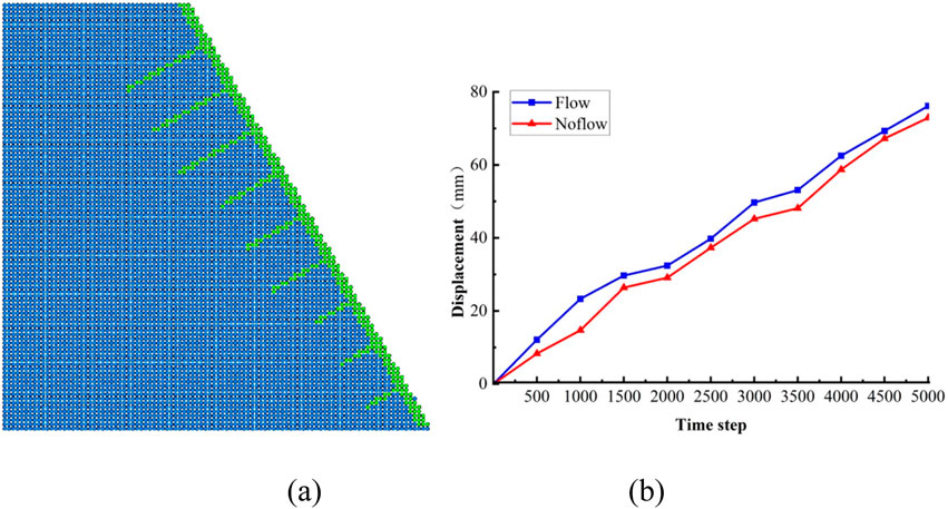
Figure 17. “ Anchor net + grouting” support simplified model and operation result monitoring. (a) “Anchor net + grouting” simplified support model. (b) Monitoring of operational results.
A comprehensive comparison of two slope stability control schemes for waste dumping sites shows that under the working conditions studied in this article, the “anchor mesh + grouting” support has better control effect. Whether in complex environments with groundwater seepage or relatively simple non seepage conditions, the anchor mesh support technology can effectively improve the stability of the slope, control the maximum sliding amount and crack development degree of the slope, greatly improve the stability of the slope, and suppress the occurrence of slope instability and sliding disasters.
7 Conclusion
(1) The critical points for significant sliding of the slope with and without seepage are divided into 1,500 and 2,000 steps. The maximum sliding amount of the slope without seepage is 7.82 m, and the angle between the sliding surface and the horizontal line is about 45°. The maximum displacement of the slope model under seepage is 10.23 m, and the sliding surface is similar to a “C” shape. The displacement of the slope increases by 30.82%, and the range and degree of instability radiation are more obvious.
(2) The development of slope cracks is mainly concentrated on the slope, developing and penetrating upwards at an angle of about 45° at the bottom of the slope, forming a relatively complete slip surface. It vigorously develops in the triangular area formed perpendicular to the top of the slope and gradually expands towards the inside of the slope top, with a small number of cracks formed inside the slope. Under the action of seepage, a certain number of cracks develop and gradually penetrate inside the slope. When running for 2,000 steps, the total number of cracks reached 3,418, an increase of 68.29% compared to the absence of seepage.
(3) The peak of seepage pressure occurs at the bottom corner of the slope, and the direction of slope sliding is basically consistent with the direction of seepage pressure. Under the action of seepage, groundwater invades the pores and cracks of the rock and soil mass, and the overall structural stability of the rock and soil mass is destroyed. When the internal structural planes of the slope weaken and cannot resist the shear stress generated by external forces, the slope exhibits sliding instability.
(4) The minimum safety factor of the slope in the research area under condition I is 1.031∼1.104. Groundwater seepage has a significant impact on the instability of the slope. Under the action of groundwater seepage, the stability of the slope is weakened, and soil erosion or sliding may occur. The anchor mesh support scheme has a good control effect on resisting the decrease in slope stability caused by groundwater seepage.
Data availability statement
The original contributions presented in the study are included in the article/Supplementary Material, further inquiries can be directed to the corresponding author.
Author contributions
YZ: Writing – original draft, Visualization, Investigation, Data curation, Writing – review and editing. YG: Investigation, Writing – review and editing, Software. RD: Investigation, Resources, Formal Analysis, Writing – review and editing, Data curation, Methodology, Validation. HM: Project administration, Methodology, Supervision, Funding acquisition, Writing – review and editing. YL: Supervision, Writing – review and editing.
Funding
The author(s) declare that financial support was received for the research and/or publication of this article. This work was supported by China National Key Research and Development Program (No 2021YFC3090403) and the special fund project of basic scientific research business fee of China Academy of Safety Production Sciences (No 2024JBKY20).
Conflict of interest
Authors YZ, YG, RD, and HM were employed by Gathay Safety Technology Co, Ltd. Author YL was employed by Zijin Mining Group Company Limited.
Generative AI statement
The author(s) declare that no Generative AI was used in the creation of this manuscript.
Publisher’s note
All claims expressed in this article are solely those of the authors and do not necessarily represent those of their affiliated organizations, or those of the publisher, the editors and the reviewers. Any product that may be evaluated in this article, or claim that may be made by its manufacturer, is not guaranteed or endorsed by the publisher.
References
Chen, C.-F., and Zhu, J.-F. (2010). A three-dimensional slope stability analysis procedure based on morgenstern-price method. J. Rock Mech. Eng. 29 (07), 1473–1480.
Chen, L. (2021). Retracted article: coupling analysis of seepage and deformation of slope based on symmetric finite element model. Arab. J. Geosci. 14, 952. doi:10.1007/s12517-021-07180-6
Chen, L.-S., Wei, B.-X., Liao, H., and Zhang, H.-B. (2020). A coupling analysis of unsaturated seepage and progressive failure of an expansive soil slope. Hydrogeol. Eng. Geol. 47 (04), 132–140. doi:10.16030/j.cnki.issn.1000-3665.201910045
Chen, S.-X., and Chen, S.-Y. (2001). Analysis of stability of unsaturated soil slope due to permeation of rainwater. Geotech. Mech. 2001 (04), 447–450. doi:10.16285/j.rsm.2001.04.023
Crosta, G., and Prisco, C. D. (1999). On slope instability induced by seepage erosion. Can. Geotechnical J. 36 (6), 1056–1073. doi:10.1139/t99-062
Dou, H.-Q., Xie, S.-H., Wang, H., and Jian, W.-B. (2023). Numerical analysis of seepage characteristics and stability for spheroidal weathered granite-like soil slopes under rainfall conditions. Acta Eng. Geol. 31 (02), 638–649. doi:10.13544/j.cnki.jeg.2022-0391
Guo, Y.-B., Zhang, C.-W., Tian, G., Liu, Y., He, Y.-J., and Li, Z.-L. (2023). Research on seepage and porewater pressure characteristics of internal dump near-natural remodeling. Coal mine Saf. 54 (02), 161–165. doi:10.13347/j.cnki.mkaq.2023.02.024
Han, J.-M., Dong, Z., Su, S.-Q., Ma, X., and Li, G.-B. (2023). Analytical solution of rainfall infiltration in homogeneous unsaturated slope and its application in loess slope. Geotech. Mech. 44 (01), 241–250. doi:10.16285/j.rsm.2022.0218
Huang, C.-G., and Ding, E.-B. (1999). Stability analysis method commonly used in slope engineering. Hydropower Stn. Des. 01.
Huang, T., Luo, X.-Y., Wu, Q., and Zheng, L.-M. (2004). Model testing study on slope stability under environment of surface water permeation. Rock Mech. Eng. 16, 2671–2675. doi:10.3321/j.issn:1000-6915.2004.16.002
Jiang, Z.-M., Xiong, X.-H., and Zeng, L. (2014). Unsaturated seepage analysis of slope under rainfall condition based on FLACЗD. Geomechanics 35 (03), 855–861. doi:10.16285/j.rsm.2014.03.016
Li, M., Miao, H.-B., Ma, M.-K., Ma, X.-Y., and Yuan, R.-Y. (2021). Stability Analysis of seepage slope based on Darcy’s law. Coal Mine Saf. 52 (05), 238–241 + 249. doi:10.13347/j.cnki.mkaq.2021.05.042
Liu, X.-L., Wu, S.-C., Han, L.-Q., Liu, Z.-Q., Cui, F., Zhang, X.-L., et al. (2024). Study on simulation and safety prevention of underground water inflow in open-pit mine. Res. Dev. Min. industry 44 (02), 151–156. doi:10.13827/j.cnki.kyyk.2024.02.023
Miao, H.-B., and Ma, M.-K. (2023). Deformation and failure mechanism and mechanical characteristics of internal dump slope under seepage condition. Open-Pit Min. Technol. 38 (02), 5–7 + 12. doi:10.13235/j.cnki.ltcm.2023.02.002
Nian, G.-Q., Chen, Z.-H., Zhou, Z.-H., Zhang, L.-F., and Bao, M. (2020). Seepage and stability analysis of fractured rock slope based on dual medium model. J. Coal. 45 (S2), 736–746. doi:10.13225/j.cnki.jccs.2020.0751
Qi, G.-Q., Huang, R.-Q., Su, B.-Y., Hu, Y.-J., and Zhan, M.-L. (2003). Numeric simulation on rainfall infiltration on rock slope. J. Rock Mech. Eng. 04, 625–629. doi:10.3321/j.issn:1000-6915.2003.04.023
Qu, X.-L., Zhang, Y.-K., Chen, Y.-R., Chen, Y.-Y., and Qi, C.-Z. (2024). Stability analysis of fractured rock slope based on seepage-deformation coupling model using numerical manifold method. Geotech. Mech. 45 (01), 313–324. doi:10.16285/j.rsm.2023.0117
Sun, J., Tian, G., Han, L., Song, R.-Z., Han, X., and Yan, S. (2021). Study on influence of water blocking of internal dumping site on stability of non-working slope. Coal Sci. Technol. 49 (12), 186–191. doi:10.13199/j.cnki.cst.2021.12.023
Tan, X., Chen, S.-X., and Yang, M. (2003). Saturated-unsaturated seepage analysis of slope under rainfall. Geotech. Mech. (03), 381–384. doi:10.16285/j.rsm.2003.03.014
Tang, D., Li, D.-Q., Zhou, C.-B., and Fang, G.-G. (2013). Slope stability analysis considering antecedent rainfall process. Geomechanics 34 (11), 3239–3248. doi:10.16285/j.rsm.2013.11.020
Tang, X.-S., Zheng, Y.-R., Wu, A.-Q., and Lin, C.-G. (2006). Stability Analysis of soil slope under seepage by PLAXIS finite element program. J. Yangtze River Acad. Sci. (04), 13–16. doi:10.3969/j.issn.1001-5485.2006.04.003
Wei, Y.-H., Wang, Z.-W., Li, B., Wang, Z.-T., Li, Y.-H., and Gong, Q.-X. (2023). Study on deformation law of normal fault and slope stability under the action of mining-seepage. Open-Pit Min. Technol. 38 (06), 21–25. doi:10.13235/j.cnki.ltcm.2023.06.006
Xu, M.-F., Jiang, X.-N., Duan, L.-M., Jiao, M.-W., and Hu, X.-F. (2019). Centrifugal loading finite element method for slope stability under damage-seepage coupling effect. J. Geotechnical Eng. 41 (11), 2103–2111. doi:10.11779/CJGE201911016
Yan, J., Huo, Z.-G., Li, H.-Y., Zhou, Y., and Liu, Y.-F. (2022). Seepage sliding analysis and stability study of sub-horizontal slope under fissure water. J. Min. Saf. Eng. 39 (03), 607–614. doi:10.13545/j.cnki.jmse.2021.0342
Yao, H.-L., Zheng, S.-H., Li, W.-B., and Chen, S.-Y. (2002). Parametric study on the effect of rain infiltration on stability of unsaturated expansive soil slope. J. Rock Mech. Eng. 07, 1034–1039. doi:10.3321/j.issn:1000-6915.2002.07.019
Yu, D.-J., Huang, Q.-B., Kang, X.-S., Chen, X., and Liu, Y. (2022a). A model test study of the interface seepage and failure mechanism of loess-filled slope. Hydrogeol. Eng. Geol. 49 (05), 119–128. doi:10.16030/j.cnki.issn.1000-3665.202202019
Yu, L., Zheng, X., Liu, Z., Zhou, C., and Zhang, L. (2022b). Multiscale modelling of the seepage-induced failure of a soft rock slope. Acta Geotech. 17, 4717–4738. doi:10.1007/s11440-022-01518-4
Keywords: structural instability, slope stability control, groundwater seepage, structural plane slip, slope disaster prevention and control
Citation: Zhang Y, Gu Y, Deng R, Ma H and Lai Y (2025) Study on the slip characteristics of the waste dump of Zijinshan Gold Copper Mine under the action of groundwater seepage. Front. Built Environ. 11:1597484. doi: 10.3389/fbuil.2025.1597484
Received: 21 March 2025; Accepted: 04 June 2025;
Published: 08 July 2025.
Edited by:
(Retired) Sudhakar Rao, Indian Institute of Science (IISc), IndiaReviewed by:
Zhang Jing, Chongqing Jiaotong University, ChinaRong Yang, Shaanxi Polytechnic Institute, China
Copyright © 2025 Zhang, Gu, Deng, Ma and Lai. This is an open-access article distributed under the terms of the Creative Commons Attribution License (CC BY). The use, distribution or reproduction in other forums is permitted, provided the original author(s) and the copyright owner(s) are credited and that the original publication in this journal is cited, in accordance with accepted academic practice. No use, distribution or reproduction is permitted which does not comply with these terms.
*Correspondence: Haitao Ma, MTE0NzMxMzk1NUBxcS5jb20=