 Alfonso Prosperi
 Michele Longo
 Paul A. Korswagen1
 Giorgia Giardina
- 1Delft University of Technology, Faculty of Civil Engineering and Geosciences, Department of Materials, Mechanics, Management and Design (3MD), Delft, Netherlands
- 2Delft University of Technology, Faculty of Civil Engineering and Geosciences, Department of Geoscience and Engineering, Delft, Netherlands
Damage assessment for masonry structures subjected to settlement is crucial for ensuring structural safety, guiding repairs, and preserving the built environment. Non-linear finite element modelling offers an effective approach for this purpose, though balancing model complexity, computational cost, and predictive reliability remains a key challenge. This study addresses the absence of a systematic comparison between macro- and simplified micro-modelling strategies for such analyses, clarifying their respective strengths, limitations, and sensitivity to key parameters. The performance and accuracy of semi-coupled NLFEM models are compared in simulating the response of a 1/10th scaled masonry façade under settlement, available from prior research. The two approaches considered are: simplified micro-modelling, where bricks are represented as expanded blocks with non-linear interfaces for mortar joints and their contact edges, and macro-modelling, where masonry is homogenised into an equivalent orthotropic composite material. The macro-models employ two well-established constitutive models, the Total Strain Rotating Crack Model (TSRCM) and the Engineering Masonry Model (EMM), to capture the non-linear cracking behaviour of masonry. Sensitivity analyses assess the influence of base interface models and the interface’s tangential stiffness. The results show how the selection of the modelling approach depends on the analysis objective: The macro-model with the Engineering Masonry Model best predicts damage severity, deviating by only 10% from the experiment, further improved by calibrating the minimum head-joint tensile strength. While all models yield similar predictions for vertical displacements of the façade, the TSRCM better captures overall and horizontal displacements, whereas the simplified micro-model more accurately represents the crack pattern. The EMM-based macro-models are the most computationally efficient, with TSRCM requiring 1.5 times the CPU time of EMM, and the micro-model requiring twice as much. The analysis also shows that the TSRCM-based macro-model is more sensitive to variations in the type of base interface models and base interface tangential stiffness, convergence criteria, incremental-iterative procedure, and analysis settings, whereas the EMM macro-model and the simplified micro-model are less affected. By identifying the strengths and limitations of each modelling approach, this study supports informed modelling choices for a more reliable assessment of settlement damage, contributing to the effective protection of existing masonry structures.
1 Introduction
Assessing settlement-induced damage in existing structures is complex due to the interaction between structural and geotechnical elements (Giardina et al., 2012). Yet the issue is highly relevant: differential settlement is a major cause of structural damage in urban areas, particularly in regions with soft soils, ageing infrastructure, or ground disturbances such as tunnelling and dewatering. Across North America, Asia, and Europe, numerous cities face ongoing challenges related to settlement-induced damage (Bucx et al., 2015; Peduto et al., 2019; Herrera-Garcia et al., 2021). Netherlands is a prime example, with over half its territory underlain by soft soils, making it particularly susceptible to settlement. National-scale studies estimate cumulative economic losses from building damage to range between €5 and €45 billion by 2050 (Hoogvliet et al., 2012; Bucx et al., 2015; Van den Born et al., 2016; Leusink, 2018; Costa et al., 2020). A clearer understanding of how settlement causes structural damage is essential for developing effective mitigation and protection strategies.
Prior research has explored the link between ground settlement and building damage using observations of existing structures, physical models, numerical simulations, or a combination of these approaches (Skempton and MacDonald, 1956; Polshin and Tokar, 1957; Bjerrum, 1963; Burland and Wroth, 1975; Burland et al., 1978; Boscardin and Cording, 1989; Charles and Skinner, 2004; Son and Cording, 2005; Son and Cording, 2007; Truong-Hong and Laefer, 2008; Netzel, 2009; Goh and Mair, 2011; Giardina et al., 2012; Giardina et al., 2013b; Mair, 2013; Peduto et al., 2017; Yiu et al., 2017; Yiu et al., 2018; Drougkas et al., 2019; Ferlisi et al., 2019; Burd et al., 2022; Dalgic et al., 2023; Prosperi et al., 2023a; Korswagen, 2024; Prosperi et al., 2024; Guo et al., 2025; Liu et al., 2025). While earlier studies introduced settlement metrics to quantify limiting values below which damage to structures does not occur (Skempton and MacDonald, 1956; Polshin and Tokar, 1957; Bjerrum, 1963), the definitions proposed by (Burland and Wroth, 1975) are the most widely adopted in scientific literature and various design codes (CEN, 2004; Peduto et al., 2019). These foundational studies also established limits for key metrics such as differential settlement, rotation, angular distortion, and deflection ratio.
Despite the valuable insights gained from observations of real structures, such data often lack completeness or fail to accurately capture distortion and settlement measurements (Son and Cording, 2005). Experiments and numerical models, on the other hand, facilitate the study of the structural response, considering controlled variations of different scenarios, e.g., building and soil features, material properties, and settlement patterns (Son and Cording, 2005; Giardina et al., 2012; Giardina et al., 2013b; Giardina et al., 2015; Prosperi et al., 2023b; Liu et al., 2025). Nevertheless, time and financial constraints restrict the ability to conduct numerous experiments to explore the full range of potential scenarios. As a cost-effective alternative, numerical models, calibrated with experimental data, provide an efficient method to study the damage to structures (D’Altri et al., 2019). Building on the foundation established by empirical and experimental studies, more recent research has advanced the understanding of settlement-induced damage by integrating insights from numerical analyses (Burd et al., 2000; Son and Cording, 2005; Netzel, 2009; Giardina et al., 2012; Giardina et al., 2013b; Yiu et al., 2017; Bejarano-Urrego et al., 2019; Ferlisi et al., 2019; Burd et al., 2022; Prosperi et al., 2023a; Korswagen, 2024; Prosperi et al., 2024).
Complex 2D or 3D non-linear finite element (NLFE) models can simulate the detailed interaction between soil and structure (Burd et al., 2000; Giardina et al., 2013b; Bilotta, 2017; Yiu et al., 2017; Burd et al., 2022; Ninić et al., 2024). Prior research has demonstrated the advantages of semi-coupled approaches, where settlements are applied to an interface accounting for soil-structure interaction, significantly reducing modelling effort and computational burden (Giardina et al., 2013b; Drougkas et al., 2019; Ferlisi et al., 2020; Korswagen et al., 2023; Prosperi et al., 2024). The advancements in computational models of structures (Netzel, 2009; Giardina et al., 2013b; Drougkas et al., 2019) have enabled the inclusion of material cracking as a response to applied settlement. This is especially important for unreinforced masonry structures, which make up most historical buildings (Giardina et al., 2013b). Quasi-brittle materials like masonry are weak and prone to cracking under tensile stress, often caused by differential settlements. Three main state-of-the-art approaches are available for the NLFE modelling of the masonry material, enabling the characterisation of cracking damage due to settlement:
• Detailed micro-modelling (in Figure 1a) involves a precise representation of the bricks, mortar, and the brick-mortar interface. While offering detailed insights, it is computationally intensive, making it ideal for small structures or detailed analyses.
• Simplified micro-modelling (in Figure 1b) represents mortar joints, along with their contact faces with the bricks, as a single interface. To maintain moment equilibrium and prevent imbalances, the thickness of these interface elements is typically set to zero.
• Macro-modelling (in Figure 1c) treats masonry as an equivalent anisotropic composite material, where bricks, mortar, and their interactions are represented in a smeared form using an equivalent continuum element.

Figure 1. Modelling strategies for the masonry material (Rots, 1994; Lourenço, 1997; Truong-Hong and Laefer, 2008). While the micro-models distinguish the brick and mortar joints and their interaction, macro-models describe the material via anisotropic continuum elements. (a) Detailed micro-modelling. (b) Simplified micro-modelling. (c) Macro-modelling.
The choice of the modelling approach generally depends on the scale and complexity of the problem: For large-scale structures, such as entire buildings or full-scale walls, a detailed brick-by-brick model (as in Figure 1a) is often impractical due to the high number of elements, making macro-models (Figure 1c) a more feasible option.
While both macro- and micro-models have been widely used to simulate masonry behaviour under in-plane or out-of-plane forces, there is a notable gap in the scientific literature regarding their performance in structures experiencing settlements. In particular, limited attention has been paid to how different modelling approaches influence the prediction of crack patterns, damage severity, displacements and deformations under differential settlements. Furthermore, the impact of analysis settings such as material properties, convergence criteria, and numerical procedures on overall model performance remains insufficiently understood. As a result, guidance for practitioners in selecting the most appropriate modelling approach is limited, which undermines the reliability of numerical assessments and reduces confidence in using such models to inform design decisions, prioritise interventions, and support the preservation of vulnerable masonry structures.
This study addresses these gaps by systematically comparing the predictive capacity, sensitivity, and computational performance of different semi-coupled models using commercially available constitutive models in simulating the response of existing masonry structures to differential settlement.
Using experimental results from prior research as a benchmark, the study offers critical insight into how modelling assumptions affect the accuracy and reliability of damage predictions. This understanding supports more informed model selection based on the specific objectives of the analysis, whether focused on displacement fields, crack patterns, or damage severity and ultimately contributes to more robust and purpose-driven structural assessments.
First, the selected case study is introduced in Section 2. The selected modelling approaches are discussed in Section 3. Emphasis is given to the effect of the material properties and modelling of the soil-structure interaction. Then, the results in terms of displacement, cracking damage and damage severity and the computational burden of the selected 2D modelling approaches are compared (Section 4) and discussed (Section 5). The conclusions are consolidated in Section 6, providing insight into the selection of the most reliable and accurate modelling strategy.
2 Case study
In prior research (Rizzardini, 2011; Giardina et al., 2012; Giardina et al., 2013b), the behaviour of a 1/10th scaled masonry façade subjected to settlement has been studied experimentally and numerically. The results of the test offer validation for the numerical models presented in this study.
The experimental benchmark represents a 1,428 × 1,186 mm scaled masonry façade (Figure 2), built using bricks of 25 × 40 × 50 mm and 2 mm thick layers of low-strength lime mortar. The sample did not account for the effect of transversal walls (Giardina et al., 2012). Soil-structure interaction in this experiment was modelled using a rubber interface with known compressive stiffness and negligible tension behaviour, assuming very low shear stiffness. A flexible steel profile was placed at the bottom of the interface. The a distributed hogging settlement profile was imposed on the façade by pushing down the left side of the supporting beam, as illustrated in Figure 3. The settlement was applied by pulling the steel profile downward for a total displacement of 11.5 mm on the scaled model.
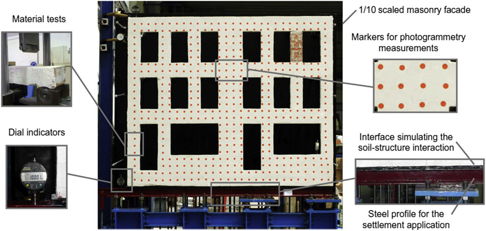
Figure 2. Main features of the experimental test of the scaled masonry façade tested in 2012 (Giardina et al., 2012). The façade is further detailed in Figure 3.
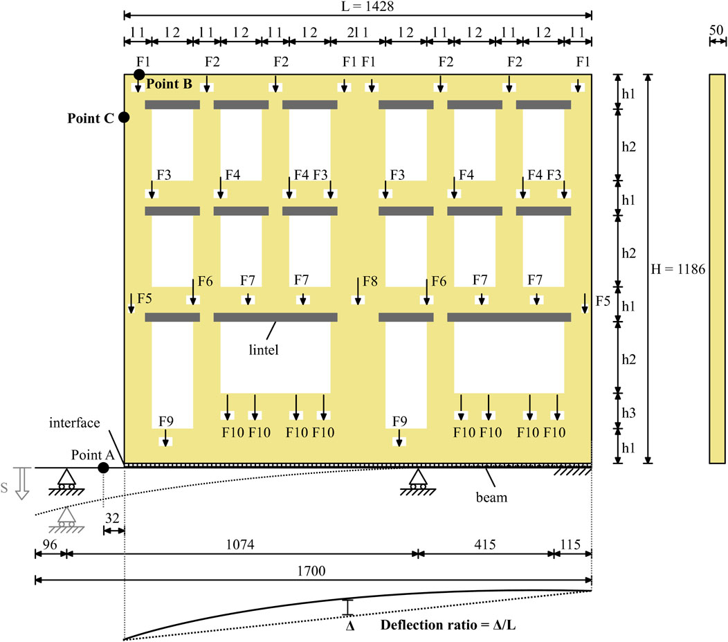
Figure 3. The scheme of the 1/10th scaled masonry façade, retrieved from (Giardina et al., 2012; Giardina et al., 2013b). Measurements in millimetres. The values of the distances and forces are reported in Table 2.
Photogrammetric measurements were conducted to monitor variations in the displacement field. Before the test, a grid of 12 mm circular markers, spaced 50 mm apart, was affixed to the model’s surface (Figure 2). Vertical and horizontal displacements at the façade’s upper left corner were tracked using dial indicators (points B, located at 60 mm and point C, located at 150 mm from the façade corner, in Figure 3). The correlation between these movements and the vertical displacement measured at the supporting beam level (point A in Figure 3) provided insight into the overall structural response. Additionally, the width of individual key cracks, identified as critical to the failure mechanism, was monitored during the test using strain gauges.
3 Two-dimensional NLFE models to reproduce the experimental results
This section introduces the 2D NLFE models used to replicate the displacements and crack patterns of the experimental façade, built with Diana FEA finite element software, version 10.9. Detailed information on the façade model is provided in Figure 3 and Table 1. An overview of all the analyses carried out in this study is shown in Table 2, whereas the details are provided in the following sections.
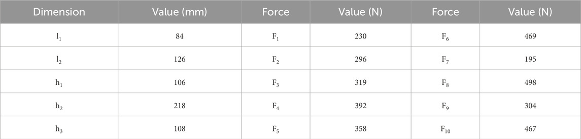
Table 1. Model geometrical dimensions and applied load values from (Giardina et al., 2012; Giardina et al., 2013b).
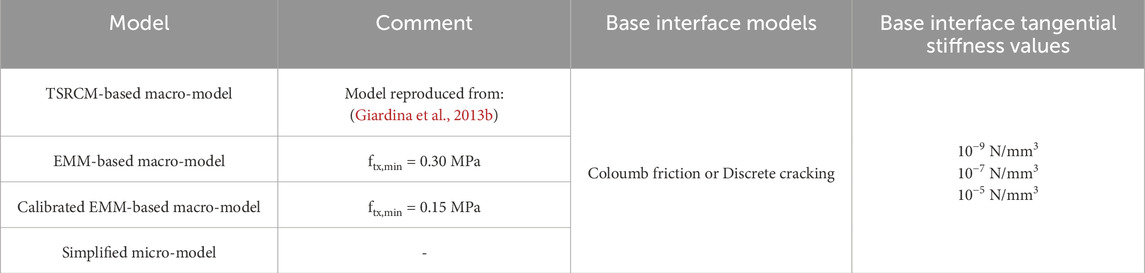
Table 2. An overview of the NLFE models adopted in this study.
3.1 The reproduced macro-models with the total strain rotating crack model and the engineering masonry model
The 2D continuum finite element model is available in (Giardina et al., 2013b), is reproduced and enhanced in this research, incorporating advancements in modelling structures subjected to settlements since the original study. The modelling approach is schematically illustrated in Figure 1c. A sensitivity study is conducted using two masonry material models: the orthotropic Engineering Masonry Model (EMM) and the isotropic Total Strain Rotating Crack Model (TSRCM). The two chosen constitutive laws are commercially available and widely used for modelling unreinforced masonry structures (Sousamli, 2024). The material properties for both TSRCM and EMM are reported in Table 3.
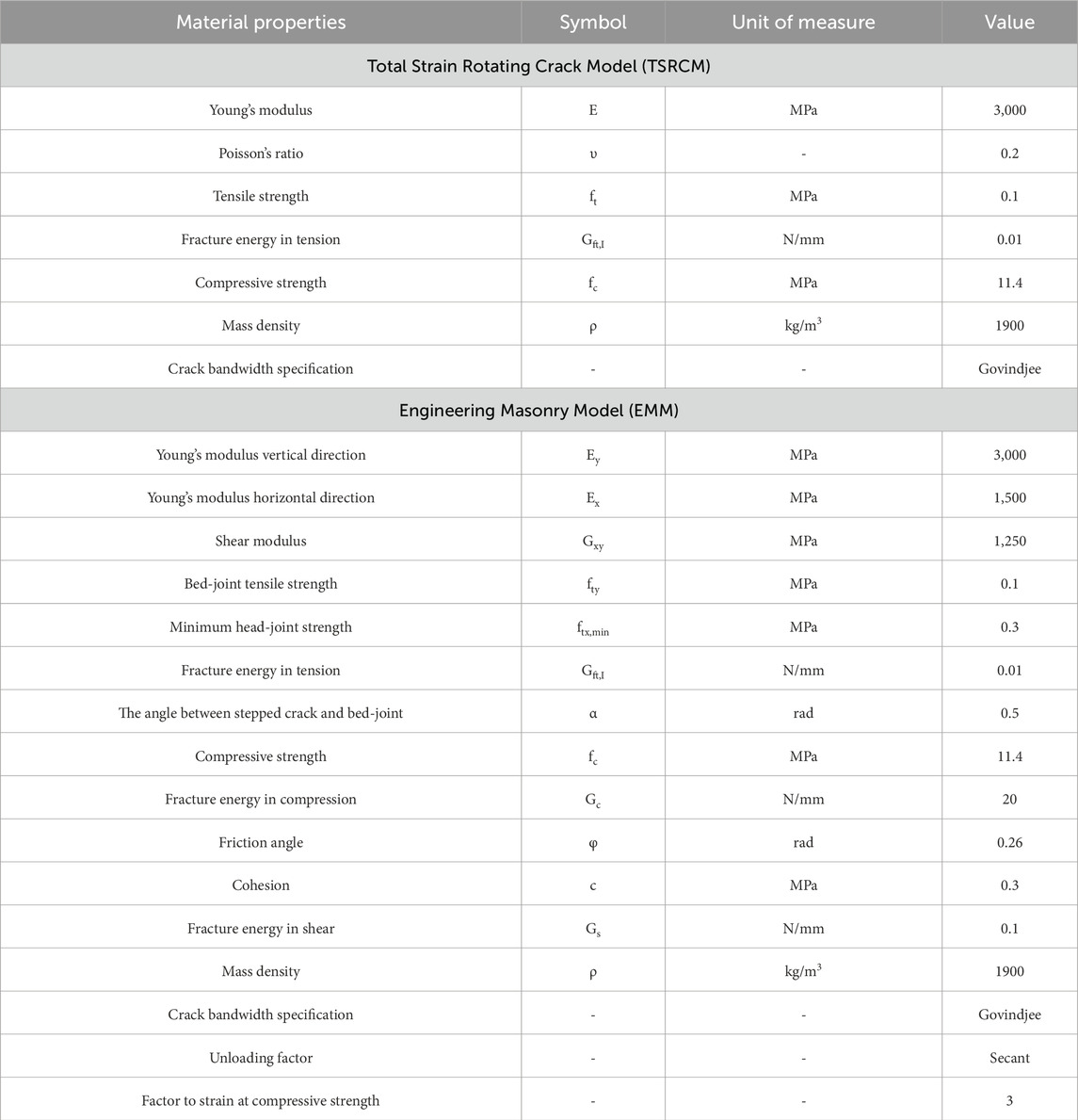
Table 3. Material properties of the TSRCM and EMM employed in the macro-models for the masonry material. The properties of the TSRCM are retrieved from (Giardina et al., 2013b).
The TSRCM, originally employed in (Giardina et al., 2013b), captures the non-linear cracking behaviour of masonry by evaluating failure mechanisms in the principal directions, including tensile and compressive failures. In contrast, the EMM, differentiates tensile failure in horizontal, vertical, and diagonal directions, horizontal and vertical compressive failure, and shear sliding.
For head-joint failure in the EMM, both the defined minimum tensile strength and the shearing properties, i.e., cohesion and friction angle, contribute to the overall strength. The minimum head-joint strength ftx,min (Figure 4), is a user-defined input that accounts for the combined effects of head-joint horizontal opening and splitting cracks in the bricks, assuming a pure vertical crack running through both bricks and head-joints. Additionally, the local shear strength component provided by the bed-joints is calculated by adding cohesion to the product of the friction coefficient and the overburden level, resulting in the final head-joint strength (Figure 4). In the TSRCM, crack opening is governed by a single user-defined tensile strength value. Once the tensile stress reaches this specified threshold, a crack initiates. The crack can then propagate in the direction of the principal tensile stress, meaning that its opening is not restricted to predefined paths but can develop dynamically based on the stress distribution in the material, as the crack orientation adapts to the loading conditions.
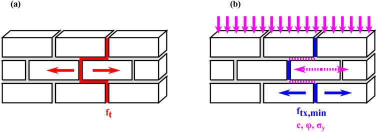
Figure 4. Material parameters defining the head-joint failure for the TSRCM and EMM adopted for the macro-models. The symbols correspond to the ones used in Table 3 (a) macro-model. (b) simplified micro-model.
The material properties of the TSRCM, reported in Table 3, have been retrieved from (Giardina et al., 2013b). In contrast, the additional material properties required for the EMM are derived either from material tests, such as cohesion and friction angle, described in (Giardina et al., 2012) or computed according to (Schreppers et al., 2016). These include Young’s modulus in the horizontal direction, shear modulus, and the minimum head-joint strength, based on available values for the fired-clay baked masonry used in the test.
The minimum head-joint strength employed in numerical analyses has been reported to range from 1.0 to 3.3 times the bed-joint tensile strength (Schreppers et al., 2016; Prosperi et al., 2023b; Wani et al., 2023; Korswagen, 2024; Sousamli, 2024). This variation depends on the type of masonry material or arises from calibration efforts. Consequently, while the value specified in Table 3 is set at 3.0 times the bed-joint tensile strength (Schreppers et al., 2016), a variation with a lower value of 1.5 times the bed-joint tensile strength is also considered for sensitivity analysis.
Above the doors and windows of the facade model, wooden lintels are included, with the material properties specified in Table 4. Settlements are applied to a steel profile supporting the façade model. The material properties of the steel profile are reported in Table 4. The cross-section of the steel profile is an I-section, with a height of 60 mm and a width of 50 mm. The flanges of the profile have a thickness of 5 mm (Rizzardini, 2011; Giardina et al., 2012). The façade is modelled by 8-node plane stress elements (8,251 in total) with 3 × 3 integration points, with a mesh size of 10.5 mm (Figure 5a).
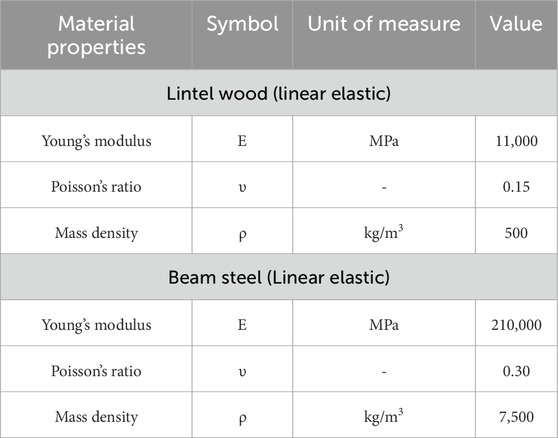
Table 4. Material properties for the lintel wood and the steel of the beam profile employed in the models.
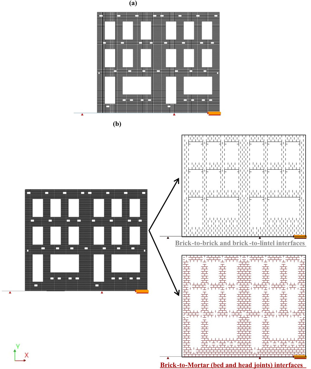
Figure 5. Screenshot of the NLFE model meshes used in this study: (a) the macro-model and (b) the simplified micro-model.
3.2 Simplified micro-model
The results of a simplified micro-model are compared against those of the macro-models. In the simplified micro-model, the bricks are modelled as independent linear elastic elements. Each brick is split in half, with an interface connecting the two portions to represent potential cracking at the midpoint of each brick (Figure 5b). Since no crushing is expected in the bricks, a discrete cracking behaviour is assigned to this interface, with the flexural strength of the bricks employed as interface tensile strength. Mortar joints and their contact edges with the bricks are represented as combined Cracking-Shearing-Crushing (CSC) interface elements. The CSC model employs a multi-surface plasticity approach, integrating three primary failure criteria: tension cut-off criterion, Coulomb Friction criterion and compression cap criterion. A key feature of the CSC model is its ability to account for the interaction between these failure modes. For instance, the development of tensile cracks can influence shear behaviour by reducing shear resistance, while shear sliding can affect the normal stress distribution, potentially leading to crushing. By incorporating these interactions, the model provides a more realistic simulation of interface behaviour under complex loading scenarios (Murgo et al., 2021; Chang, 2022; DIANA FEA bv, 2024). The modelling approach is schematically illustrated in Figure 1b. The material properties are listed in Table 5.
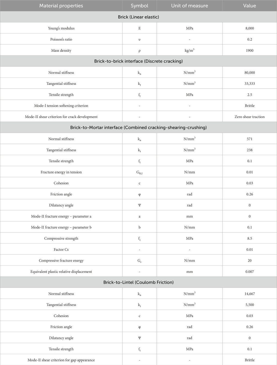
Table 5. Material properties adopted for the simplified micro-model.
The lintels and steel profiles are modelled using the same approach employed for the macro-models selected in this study, and with the material properties summarised in Table 4. The mesh size is 9 × 10.5 mm and 20,186 elements are obtained after meshing (Figure 5b).
3.3 Coulomb friction and discrete cracking for the base interface
The models use a non-linear interface between the building base and the steel profile (Giardina et al., 2013b). A sensitivity study is conducted using two base interface models: Coulomb friction and Discrete Cracking. Coulomb friction interfaces assume the interaction is governed by a frictional behaviour, as used in the reference study, while Discrete Cracking interfaces model discontinuities between elements based on the relation between tensile tractions and relative displacements normal to the interface, keeping the shear behaviour as linear elastic. The properties of both interfaces are listed in Table 6.
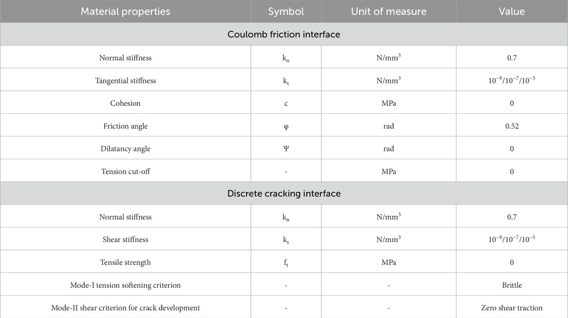
Table 6. The material properties adopted for the interface elements between the façade and the steel profile in both macro- and simplified micro-models.
Following the approach in the reference study, a negligible value for the stiffness in shear is assigned, corresponding to a value of 10−9 N/mm3. Large differences in stiffness values can cause ill-conditioning in the stiffness matrix, potentially affecting the numerical solution and the reliability of the analysis. For this reason, sensitivity analyses are carried out considering two additional negligible (compared to the normal stiffness values) values of the tangential stiffness kt: 10−7 and 10−5 N/mm3.
3.4 Load and settlement application and incremental-iterative analysis
In the laboratory test, first, the façade is subjected to vertical loads (Figure 3; Table 2), followed by settlement, which is induced by pulling downward the left end of the base steel profile at point A. In the numerical models, three subsequent loading phases are used to apply the loads: First, the self-weight is applied in five steps, then the vertical overburden loads are applied in five steps, and finally, the settlement is applied with a rate of 0.5 mm per step (30 steps). The displacements are reset to zero before the application of the settlement.
The features of the adopted numerical integration scheme are reported in Table 7. The Quasi-Newton method avoids computing a new stiffness matrix at each iteration. Instead, it utilises information from the previous solution vectors and the out-of-balance force vector at each increment (DIANA FEA bv, 2024). Three convergence norms for the self-weight and overburden are used to ensure a more robust and reliable evaluation of convergence because of the settlement application, thus improving the numerical stability.
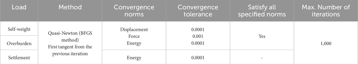
Table 7. Characteristics of the incremental-iterative procedure.
3.5 Damage assessment
A smeared cracking approach is adopted in the macro-models, treating cracking as a distributed effect. In contrast, in the simplified micro-model, the crack width can be determined from the plastic relative displacements (i.e., normal openings) of the interfaces. In both cases, the width of cracks can be retrieved for each integration point and exported as tabulated outputs at each step of the analysis. Knowing the crack width throughout the settlement load application enables a comparison of the damage severity with that observed in the experiment. Moreover, the tabulated outputs of the FEM models can be used to quantify the damage progression and accumulation using one single scalar value (Korswagen et al., 2019; Korswagen, 2024), Ψ in Equation 1:
Where “n” is the number of cracks, “cw” is the weighted crack width (in mm) calculated with Equation 2:
Where “ci” in Equations 2, 3 is the maximum crack width of crack “i” in millimetres, and “Li” is the length in millimetres. The crack width is composed of both the opening (co) and sliding (cs) components. A summary of the relation between Ψ and the approximate crack width for the various damage levels is presented in Table 8.
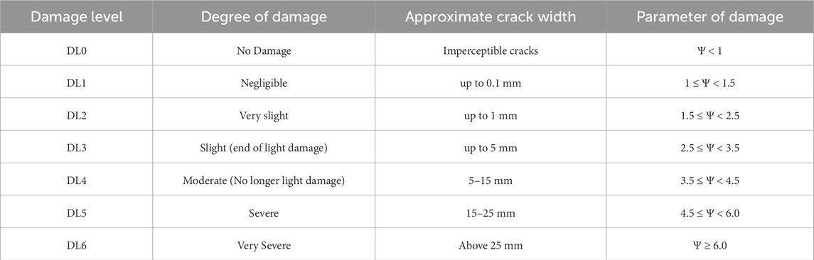
Table 8. Damage scale with the classification of visible damage and the corresponding discretization of the damage parameter Ψ (from (Burland et al., 1978; Grünthal, 1998; Korswagen et al., 2019)).
4 Results
4.1 Sensitivity to the base interface models and base interface tangential stiffness
Figure 6 shows the CPU time of each analysis, offering insight into their computational efficiency. Interestingly, the TSRC-based macro-model requires 1.5 times the CPU time of the EMM models. Overall, the simplified micro-model is the most CPU-intensive, with its required time ranging from 1.6 to 2.6 times that of the macro-model with EMM. The difference in CPU time between the selected macro- and micro-models is likely due to the smaller number of elements in the former and the added complexity of the material models used in the latter. No significant differences are observed based on the type of base interface or variations in its shear stiffness.
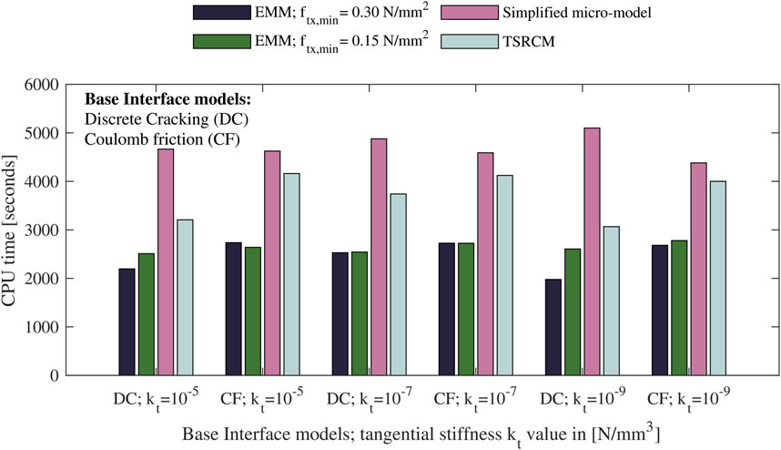
Figure 6. CPU time of each numerical analysis considered in this study.
Convergence is observed for all the steps of each selected analysis. Although the iterative solution converges, differences in structural response remain. Convergence ensures numerical accuracy but does not guarantee the solution is close to the true one. The behaviour of the different models is further examined by analyzing the maximum crack width at each step of the analysis (in Figure 7), as well as the displacements at points B and C (in Figure 8). The results of the models are compared against the ones from (Giardina et al., 2012; Giardina et al., 2013b).
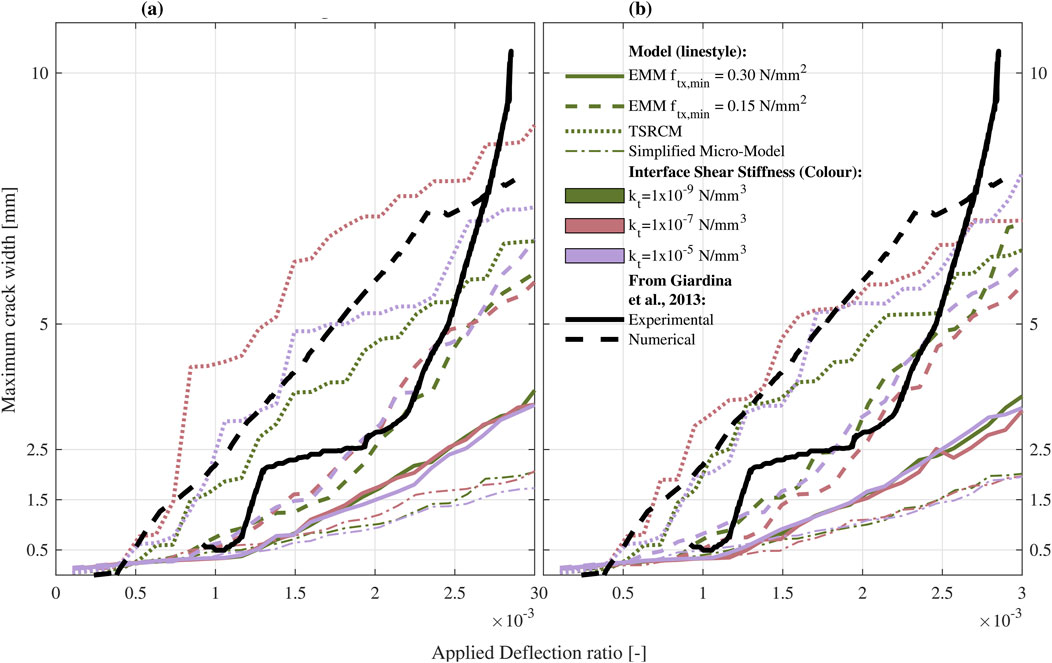
Figure 7. Applied deflection ratio versus maximum crack width. Subplot (a) shows the results of the model using Discrete Cracking interfaces, while subplot (b) refers to Coulomb Friction interfaces. Different line styles distinguish the models, while different colours denote the adopted values of interface tangential stiffness. The results of the models are compared with the experimental and numerical ones from (Giardina et al., 2012; Giardina et al., 2013b).
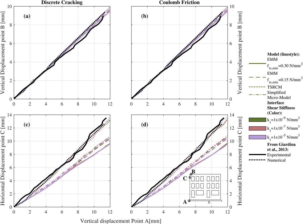
Figure 8. (a) Vertical displacement of point B and (c) horizontal displacement of point C as a function of the applied settlement, using Discrete Cracking interfaces. (b) Vertical displacement of point B and (d) horizontal displacement of point C as a function of the applied settlement, using the Coulomb Friction interfaces. All modelling strategies are compared with the experimental and numerical results from (Giardina et al., 2012; Giardina et al., 2013b).
While the macro-models with EMM and the micro-models exhibit minimal sensitivity to the adopted value of the interface tangential stiffness or the material model used for the interface, the reproduced macro-model with TSRCM demonstrates a higher sensitivity to these parameters (Figure 7). The variability of each set of curves is herein quantified by the Coefficient of Variation (CoV). Accordingly, the curves in Figure 7 are used to compute CoV for each type of model distinguished by the value of tangential interface stiffness and by the type of interface model. The values of the CoV vary depending on the considered step, for this reason, only the minimum and the maximum values are considered and reported in Table 9.
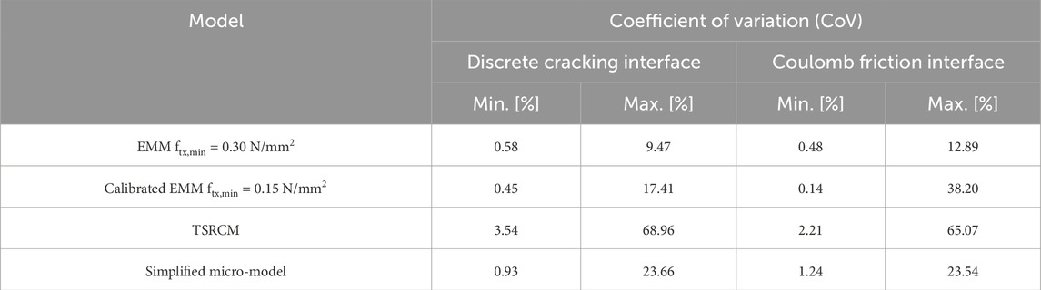
Table 9. Maximum and minimum values of the Coefficient of Variation (CoV) computed for the three shear interface values for each model, distinguished by the interface type.
The macro-model with TSRCM has the highest variability, ranging from a minimum of 2%–69%, which aligns with the visual observations shown in Figure 7. The model with the EMM and ftx,min of 0.30 MPa demonstrates the least variability. The model using TSRCM with a kt equal to 10−5 N/mm3 is the one that best replicates the numerical results published in the reference study, for both the selected interface models. Therefore, this value is considered the reference for the analyses presented in the following sections.
For applied deflection ratios below 2.5 × 10⁻³, both the micro-model and the model with EMM and an ftx,min of 0.30 MPa tend to underestimate the maximum crack width compared to the experimental results. In contrast, the calibrated macro-model with EMM and ftx,min of 0.15 MPa shows good agreement, while the TSRCM-based model overestimates the damage severity. However, for deflection ratios above 2.5 × 10⁻³, the experimental trend reveals a rapid increase in the maximum crack width, which the numerical models do not capture. Additional considerations on crack patterns are discussed in the following sections.
Figure 8 compares the displacements at points B and C with the displacement applied at point A across different models. All models show good agreement in vertical displacement at point B. However, horizontal displacements vary, with only the macro-model using TSRCM capturing the experimental behaviour. The EMM and simplified micro-models exhibit a stiffer response, resulting in smaller horizontal displacements. For example, when the applied vertical displacement at point A is 10 mm, the horizontal displacements at point C from the EMM and simplified micro-model range from 8 to 9 mm, approximately 20%–30% lower than the experimental value of around 11.5 mm.
4.2 Comparison of displacement fields between the experiment and the NLFE macro- and simplified micro-models
With the availability of photogrammetric measurements over the grid points of the experimental masonry façade, displacement fields from the experiment can be plotted at various stages and compared with the results from the numerical model.
Figure 9 compares the displacement fields to discuss the models’ performance in representing the overall displacements. For an applied displacement of 2.5 mm (Figures 9a1–e1), the displacement fields show good agreement. However, the experimental façade exhibits a rapid increase in displacement at the top, which the model does not capture accurately. The entire left portion of the façade shows higher displacements than those observed in the models, which appear more homogeneous. The TSRCM model most closely matches the experimental results, although all models underestimate the displacement magnitude in the central part of the façade.
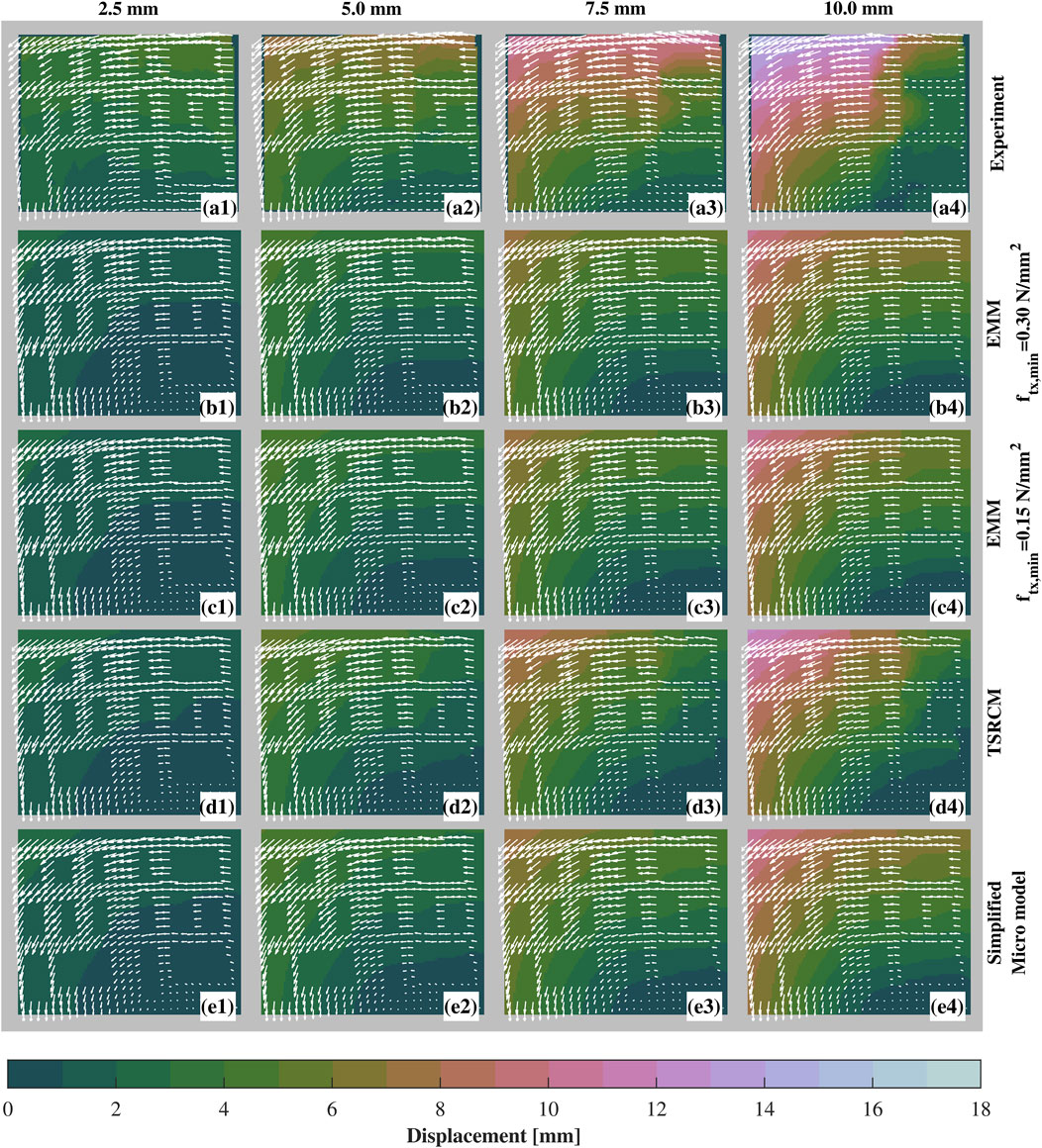
Figure 9. Displacement fields of the experiment and the selected macro- and micro-numerical models. The contour plots represent the magnitude of the displacements, whereas the arrows show the direction of the displacement of each point. Plots from 1–4 correspond to different applied displacements, i.e., 2.5, 5.0, 7.5, 10.0 mm, whereas (a) represents the results of the experiment, (b) macro-model with EMM and ftx,min equal to 0.30 N/mm2, (c) macro-model with EMM and ftx,min equal to 0.15 N/mm2 (d) macro-model with TSRCM, and (e) simplified micro-model.
4.3 Comparison of crack patterns and damage severity between the experiment and the NLFE macro- and simplified micro-models
While the relationship between the applied settlement and the crack width is detailed in Figures 7, 10 illustrates the crack patterns throughout the analyses, aiming to distinguish the overall failure mechanism of the façade. The smallest crack width observed during the experiment corresponds to 0.044 mm (Giardina et al., 2012). To ensure a consistent comparison, cracks narrower than 0.04 mm are not shown in the crack patterns of the models.
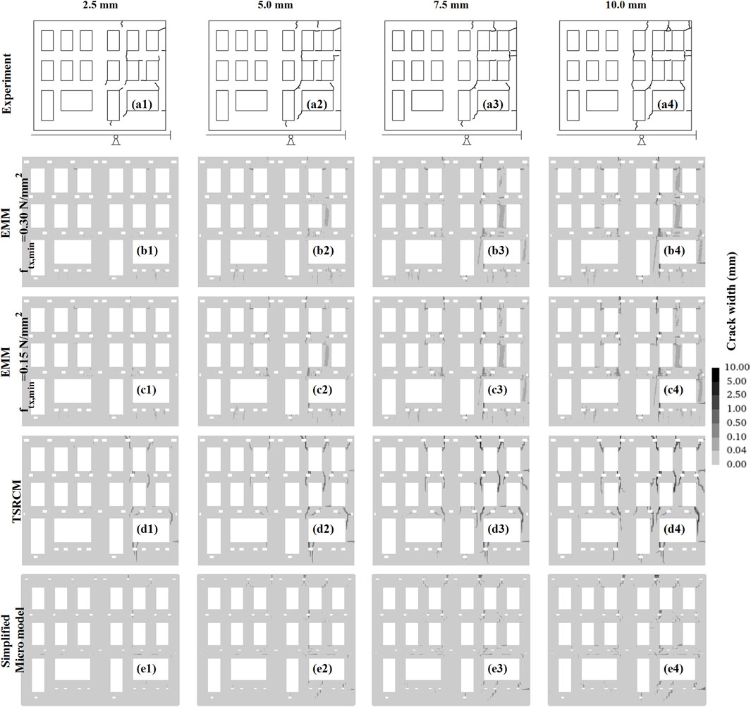
Figure 10. Crack patterns of the experiment and the selected macro- and micro-numerical models. Cracks narrower than 0.04 mm are not shown, for consistency with the experimental data. Plots from 1–4 correspond to different applied displacements, i.e., 2.5, 5.0, 7.5, 10.0 mm, whereas (a) represents the results of the experiment, (b) macro-model with EMM and ftx,min equal to 0.30 N/mm2, (c) macro-model with EMM and ftx,min equal to 0.15 N/mm2 (d) macro-model with TSRCM, and (e) simplified micro-model.
The crack pattern of the TSRCM-based macro-model reproduces with good accuracy the damage mechanism of the model reported (Giardina et al., 2013b; Giardina et al., 2015) in terms of maximum principal strains.
Cracks form exclusively on the right side of the façade during the experiment. While most cracks in the models also appear on the right side, cracks are also detected on the left side. However, some cracks observed in the experiments do not always appear in the models, and vice versa. In the TSRCM model, cracks are localized and follow a diagonal pattern around the openings. Conversely, the EMM models show more smeared cracks, typically following vertical or horizontal directions. However, the micro-model results in less damage than the experiment or macro-models, with cracks primarily following a stair-step pattern. Overall, the macro-model with TSRCM exhibits the most severe cracking, with the highest number and widest cracks compared to the other models. The EMM-based macro-models and the simplified micro-model follow it.
The variations in crack patterns highlight that evaluating damage severity solely based on the maximum crack width is inadequate for accurately representing the damage severity. Therefore, the damage parameter Ψ, briefly described in Section 3.5, is computed for all the steps of the numerical analyses and the experiment, and compared in Figure 11. Crack width measurements from the experimental façade are available for applied displacements ranging from 3.5 mm to 11.5 mm, so the comparison between the models and the experiment is limited to this range. While the damage parameter Ψ computed for the models accounts for the number of cracks, their width, and length, the parameter derived from the experimental results is limited to the number of cracks and their width, as crack length measurements are not available. Since the analytical formulation of Ψ incorporates weighted crack widths by their length, error bands are considered in Figure 11, to account for the simplification applied to the experimental results.
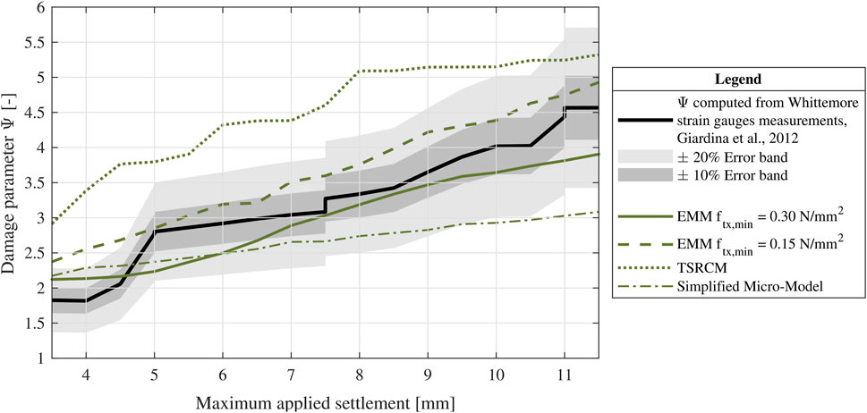
Figure 11. Maximum applied settlement against the damage parameter Ψ during the application of the settlement load: experimental vs macro- and simplified micro-models using a Coulomb friction interface and a kt = 10−5 N/mm3. The width of the cracks measured during the experiment is retrieved from (Giardina et al., 2012). Crack width measurements from the experimental façade are available for applied displacements ranging from 3.5 mm to 11.5 mm. Therefore, the comparison between the models and the experiment is limited to this range.
All the models overestimate the damage for applied displacements below 4.5 mm, whereas better agreement with the experimental results is observed for higher applied displacements. Figure 11 confirms the trends observed in Figure 7: in terms of damage severity, the EMM-based macro-models exhibit the best agreement with the experimental results, while the simplified micro-models underestimate the damage and the TSRCM-based macro-model overestimates it. Overall, the damage severity assessed with the EMM-based macro-models falls within the 10% error band of the experimental results. For applied displacements greater than 4.5 mm, the damage severity estimated with the TSRCM is 17%–56% higher than the experimental results.
5 Discussion
5.1 Preliminary sensitivity analyses for base interface model and interface tangential stiffness values
The results of the sensitivity analysis revealed that the type of interface model (Coulomb vs Discrete cracking) has a limited impact on the outcomes of the macro-model with EMM or the simplified micro-model. In contrast, the macro-model with TSRCM exhibits greater variability. The trends of the applied deflection ratio against the maximum crack width support this observation. When considering both the maximum and minimum CoV values, the interface type does not significantly influence the magnitude of the CoV for each model; instead, the variability of the results is influenced by the interface tangential stiffness. Specifically, the TSRCM shows a maximum CoV of 69%, followed by the EMM models with a calibrated value of ftx,min (38%), the simplified micro-model (24%), and the EMM (13%).
5.2 Difference with the macro-model with TSRCM published in prior research
As briefly mentioned in Section 3.1, the TSRCM-based macro-model replicates the model from (Giardina et al., 2013b). The results of the reproduced TSRCM-based model show minor differences compared to the reference study, as summarized in Table 10 and discussed in the following.
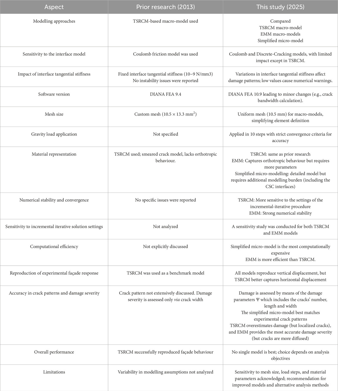
Table 10. Comparison of modelling approaches and key aspects between the reference research (Giardina et al., 2013b) and this study.
Since the reference study, advancements in DIANA FEA software (from version 9.4–10.9) have introduced changes that influence the results. Notably, the crack bandwidth algorithm differs, and while (Giardina et al., 2013b) employed a custom 10.5 × 13.3 mm mesh, a uniform 10.5 mm mesh is used here for simplicity, reducing additional complexity. Although the impact of these factors has not been specifically assessed in this study, other features are expected to have a greater influence. For instance, the type of constitutive model used for the base interface has been observed to influence the results. The reference publication employed a no-tension interface with a Coulomb friction criterion (Giardina et al., 2013b). This interface has been reproduced and compared with a Discrete-Cracking model, as detailed in Section 3. The Coulomb friction interface better replicates the results from the reference study, though the Discrete-Cracking model is a viable alternative. With the interface tangential stiffness value (kt) of 10−9 N/mm3 used in (Giardina et al., 2013b), a possible concern is related to the large differences in the stiffness matrix, potentially leading to unstable solutions. Variations in the kt can influence façade damage, as shown in sensitivity analyses in (Giardina et al., 2015), which considered the combined effect of shear stiffness and horizontal settlement components. In contrast, the analysis here focuses on the specific impact of kt on the reproducibility of the experimental test.
A different approach to applying gravity loads is also used. In this work, self-weight and additional vertical load are applied in 10 steps with three simultaneous convergence criteria, ensuring high numerical accuracy and stability before settlement is applied. In the previous model (Giardina et al., 2013b), it is not specified how many gravity load steps have been applied. A different application of gravity loads influences the initial stress distribution and, consequently, the response to settlement.
Overall, the reproduced model aligns with the one in (Giardina et al., 2013b). Nevertheless, the challenges encountered in its reproduction highlight how variations can emerge even when modelling the same case, underscoring the importance of thoroughly documenting all aspects of the research process for transparency, reproducibility, and understanding of potential discrepancies.
5.3 The sensitivity of the EMM and TSRCM to the settings of the incremental iterative solution
Both the TSRCM and EMM are available in the selected FE software and have been used in prior research to reproduce or predict the response of masonry structures and are well-established compared to more recently developed non-linear models. However, the current literature lacks comparisons of these material models’ performance in capturing the response to settlements, which is the primary focus of this research. In general, the EMM has been observed to have good, strong numerical stability and reliable convergence (Sousamli, 2024). Although prior research has used it to accurately reproduce test results (Korswagen, 2024), the model has limitations in damage localization when subjected prevalently to shear loading, as cracks tend to be diffused rather than localized, as observed in the TSRCM (Schreppers et al., 2016; Sousamli, 2024).
While it is widely recognized that material models require calibration of material properties to reproduce the response of experimental tests accurately, it is important to note that altering the features of the incremental-iterative solution procedure and convergence criteria also influences the results. Different material models can be more or less sensitive to such variations. Prior to the analysis presented in this study, a preliminary sensitivity study was conducted to identify the features of the incremental-iterative solution procedure that best reproduce the results of the reference study. This sensitivity study was then extended to the macro-model using the EMM (with the ftx,min = 0.30 N/mm3), and the results are presented in Figure 12.
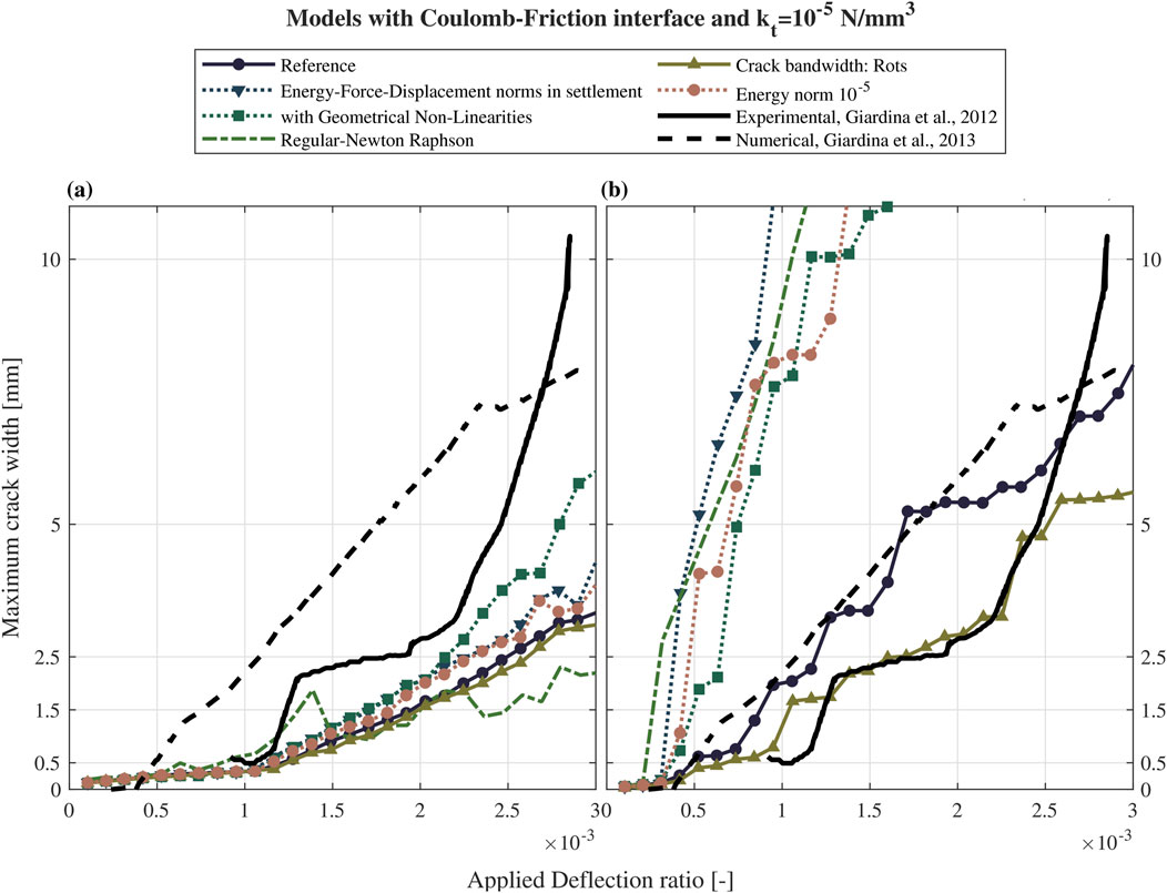
Figure 12. Sensitivity of the EMM and TSRCM adopted for the macro-models to different features and settings of the incremental-iterative procedure. (a) Engineering masonry model (EMM), (b) Total Strain rotating crack model (TSRCM).
The results indicate that the TSRCM model is significantly more sensitive to variations in the features of the incremental-iterative procedure compared to the EMM. For the EMM-based macro-model, most results are in good agreement, except for the model incorporating geometric non-linearities, which can severely impact numerical stability, and models utilizing the Regular Newton-Raphson method for iteration, where some non-convergent points are observed. In contrast, the TSRCM-based macro-model achieves convergence in all analyses, except for a single step in the model employing energy, force, and displacement norms during the settlement application. However, the results for TSRCM-based macro exhibit high sensitivity, resulting in irregular discrepancies.
While it is widely recognized that convergence in finite element analyses is a necessary condition for reliability, it is not sufficient on its own to guarantee the accuracy or appropriateness of the analyses. The sensitivity analysis results confirm this observation and further underscore the need to develop more accurate material models that are less sensitive to such variations. This advancement is crucial for improving the accuracy of structural response predictions. Although these aspects are not the primary focus of this study, further research is recommended to investigate their effects in greater detail.
5.4 Simplified micro- versus macro-models reproducing the experiment and comparison with prior research
While this study highlights the strengths and limitations of the modelling approaches, with particular emphasis on the response of structures subjected to differential settlements, the discussion that follows also considers the broader context of state-of-the-art comparisons between micro- and macro-modelling strategies. These comparisons span both quasi-static and dynamic actions and involve a range of constitutive laws and software packages.
In this study, the performance of the various models is initially evaluated based on computational time. As all the analyses do not show non-convergent steps, the CPU time provides a good indication of the computational costs of the model. The most computationally expensive model, as expected, is the simplified micro-models, due to the highest number of elements, followed by the macro-models with TSRCM and the ones with EMM. One argument supporting the use of macro-models is their computational efficiency compared to micro-models (Truong-Hong and Laefer, 2008; Murano et al., 2023; Sousamli, 2024). Although the EMM involves more parameters and thus a more complex definition of a constitutive model compared to the TSRCM, it is distinguished by a direct definition of the relationship between total stresses and strains along the material directions that align with the global axes. In contrast, the TSRCM requires a transformation from the principal to the global direction (Sousamli, 2024). As a result, the EMM outperforms the TSRCM in terms of computational efficiency.
In this study, the Total Strain Based macro-model uses a rotating crack approach to accurately reproduce the model in (Giardina et al., 2013b). Compared to the models with TSCM-fixed, models with TSCM-rotating have been observed to have a more consistent response with EMM-based models (Truong-Hong and Laefer, 2008), allowing a more equitable comparison.
While all the selected models can adequately reproduce the vertical displacements of the experimental 1/10th scaled masonry façade, the TSRCM-based macro-model better represents the horizontal displacements measured in the control point C, compared to the model with EMM and the simplified micro-model. The additional comparison between the experiment’s overall deformation and the model reveals that all the models underestimated the overall horizontal deformation of the façade, resulting in stiffer behaviour in the horizontal direction, particularly in the central part of the wall.
Prior research has observed how the selection of the constitutive law for masonry strongly influences the activation of different failure mechanisms and, hence, the response of the structure (Fusco et al., 2021; Fusco et al., 2022). In particular, EMM has been observed to provide a more accurate response of the damage response compared to the TSCM (Schreppers et al., 2016; Shabani and Kioumarsi, 2022; Ademović et al., 2024). In this study, the EMM models and the simplified micro-model correctly localize the damage mainly in the right part of the façade, whereas additional cracks open also in the left portion in the macro-model with TSRCM. The cracks in the TSRCM model are more localized, whereas in the EMM model, the cracks are more diffuse, making them less realistic compared to the experiment. The best agreement in terms of crack patterns with respect to the experiment is achieved with the simplified micro-model. Regarding the damage severity, the EMM models provide the most accurate prediction, while the TSRCM overestimates the damage, and the simplified micro-model underestimates it.
Based on the analyses presented in this study, it can be concluded that the choice of a modelling approach for structures undergoing settlements, including the constitutive relationship, depends on the specific purpose of the analysis: for instance, in this research, while the simplified micro-model more accurately represents the overall crack pattern, the severity of the damage is better captured by the (EMM-based) macro-models.
5.5 Limitations and recommendations
The non-linear finite element (FE) analysis of masonry structures is known to be influenced by the specific constitutive model adopted, modelling assumptions, and incremental-iterative settings. This study examines variations in incremental-iterative solutions and soil-structure interfaces while excluding factors such as mesh characteristics, load step size, and material parameter sensitivity, as these have been extensively addressed in previous research (Al-Chaar and Mehrabi, 2008; Mukherjee et al., 2011; Giardina et al., 2015; Bejarano-Urrego et al., 2018; Fusco et al., 2021; Fusco et al., 2022; Prosperi et al., 2023b; Korswagen, 2024; Sousamli, 2024). Overall, macro-modelling represents the most appropriate approach for practice-oriented engineering applications, offering a balanced trade-off between accuracy and computational efficiency when compared to micro-modelling (Murano et al., 2023; Sousamli, 2024).
The results indicate that none of the selected modelling approaches fully capture the behaviour of the experimental façade, underscoring the need for advancements in the modelling of masonry structures undergoing settlements. This may involve developing new constitutive relationships or exploring alternatives to traditional incremental-iterative non-linear analyses, such as the Sequentially Linear Analysis (SLA) (Rots et al., 2007). Future research should aim to advance constitutive models for masonry to enhance the accuracy of damage prediction and enable the integration of damage mechanisms with time-dependent behaviour such as creep and relaxation, as explored in studies like (Van Zijl et al., 2001; Roca et al., 2012). These effects are particularly relevant for capturing the long-term response of structures subjected to settlement over long terms, i.e., decades (Netzel, 2009; Giardina et al., 2013a). In addition, discrete element modelling offers a valuable approach for studying the response of URM façades to settlement (Ehresman et al., 2021), although it is generally associated with increased computational demands.
Additionally, evaluating different software packages can help identify potential discrepancies and advantages, contributing to improved modelling accuracy. In this study, the Engineering Masonry Model (EMM) and the Total Strain Rotating Crack Model (TSRCM) are selected as constitutive laws for the macro-models due to their commercial availability within the chosen software package and their widespread use in modelling unreinforced masonry (URM) structures (Sousamli, 2024). While this study focuses on a specific case, broader insights into damage prediction, displacement accuracy, and computational demand could be gained by exploring alternatives, including existing open-source or non-commercially available constitutive models.
The response of the FE models is compared against the experimental results of a 1/10th scaled masonry façade. In one-gravity (1 g) masonry testing, as adopted in the experiment considered here, appropriate scaling requirements must be addressed to minimise unintended scale effects (Laefer et al., 2011). In the considered experimental test, scale factors and additional loads have been applied to reproduce the real stress gradient, providing a practical alternative to more complex methods such as centrifuge testing (Giardina et al., 2012). Furthermore, (Giardina et al., 2015), explored the influence of the scale effect on the response of the TSRCM-based macro-model, comparing it against a true-scaled numerical model. The results of the two analyses showed substantial agreement in terms of displacement in the control points and maximum principal strains. However, further analyses are needed to fully understand the impact of scale, especially regarding damage severity, since crack width and length may be affected by the façade’s dimensions. Prior research (Liu et al., 2025) using scaled models has also applied the same scaling factor used for the structure to the crack widths associated with the various damage categories presented in Table 8. While this aspect does not influence the comparison between the models and the experimental benchmark, which represents the focus of this study, it may have implications for the interpretation of absolute damage levels and their correspondence to real-scale structural behaviour.
Finally, while this study focuses on one specific façade geometry and masonry material, future research should apply the proposed methodology to other scaled experiments, incorporating varied geometries, materials, and boundary conditions, to evaluate its general applicability and reliability across diverse structural scenarios.
6 Conclusion
In this study, it was observed that the macro-model employing the Engineering Masonry Model (EMM) provides the most accurate representation of damage severity, with predictions deviating by only 10% from experimental results, further refined by calibrating the minimum head-joint tensile strength. In contrast, the macro-model with the Total Strain Rotating Crack Model (TSRCM) more effectively captures the overall displacements of the experimental façade, while the simplified micro-model best represents the crack pattern.
Specifically, the findings indicate that:
• Finite element analyses of macro-models using the EMM are the most computationally efficient. The macro-model with the TSRCM requires 1.5 times the CPU time of EMM models, while the simplified micro-model requires twice as much.
• The results of macro-models using EMM and the simplified micro-model are largely unaffected by the type of base interface model or the chosen interface tangential stiffness. In contrast, the TSRCM model is particularly sensitive to these factors. Analysis of the maximum coefficients of variation (CoV) across the different models shows that the TSRCM model can be up to twice as variable as the models using EMM.
• Damage severity, assessed by maximum crack width, shows that macro-models using EMM align more closely with experimental results than TSRCM models or the simplified micro-model.
• Damage severity is further evaluated using a damage parameter that accounts for the number of cracks, their length, and width. Although all models initially overestimate the damage for low applied displacements, the EMM-based macro-models show only a 10% difference from the experimental results at higher displacements.
• The macro-model with EMM and a calibrated minimum head-joint strength (ftx,min) of 0.15 MPa (1.5 times the bed-joint tensile strength, fty) shows better agreement with the experiment than the same model with an ftx,min of 0.30 MPa (3 times fty). This highlights the importance of accurately calibrating this parameter based on the application.
• While all models adequately capture the experiment’s displacements, none fully reproduce the observed crack pattern. Cracks initiate and propagate in areas not always consistent with the experimental results. However, overall, the cracking mechanism aligns well between the models and the experiment.
• Sensitivity analyses show that the results obtained with TSRCM can vary significantly based on the settings used for the iterative-incremental procedure, while the EMM is less sensitive to these changes. In some cases, specific setting combinations can improve the accuracy of TSRCM models, whereas others may lead to a rapid progression of damage, thereby overestimating the damage severity compared to the experimental results. Further research is recommended to explore these effects.
Overall, this research provides essential guidance for selecting and calibrating finite element modelling strategies for masonry structures affected by settlement. By clarifying how different modelling assumptions and analysis settings influence damage prediction, displacement accuracy, and computational performance, the study enables more informed and purpose-driven modelling choices. The application discussed focuses on an experimental test of a 1/10th scaled façade undergoing settlement, which was reproduced using both simplified micro- and macro-models. Beyond the specific case study, the findings lay the groundwork for improving modelling practices in both research and engineering applications, particularly in settlement-prone urban environments.
Data availability statement
The original contributions presented in the study are included in the article/supplementary material, further inquiries can be directed to the corresponding author.
Author contributions
AP: Conceptualization, Data curation, Formal Analysis, Investigation, Methodology, Software, Visualization, Writing – original draft, Writing – review and editing. ML: Conceptualization, Formal Analysis, Methodology, Software, Writing – original draft, Writing – review and editing. PK: Conceptualization, Funding acquisition, Resources, Writing – review and editing, Supervision. GG: Supervision, Writing – review and editing. JR: Funding acquisition, Supervision, Writing – review and editing.
Funding
The author(s) declare that financial support was received for the research and/or publication of this article. Participation and funding provided by Instituut Mijnbouwschade Groningen (IMG) and Commissie Mijnbouwschade (CM) is gratefully acknowledged.
Conflict of interest
The authors declare that the research was conducted in the absence of any commercial or financial relationships that could be construed as a potential conflict of interest.
Generative AI statement
The author(s) declare that no Generative AI was used in the creation of this manuscript.
Publisher’s note
All claims expressed in this article are solely those of the authors and do not necessarily represent those of their affiliated organizations, or those of the publisher, the editors and the reviewers. Any product that may be evaluated in this article, or claim that may be made by its manufacturer, is not guaranteed or endorsed by the publisher.
References
Ademović, N., Hadzima-Nyarko, M., Zagora, N., and Stojnović, V. (2024). Various numerical modeling procedures of XIX-century masonry building. Eng. Struct. 301, 117361. doi:10.1016/j.engstruct.2023.117361
Al-Chaar, G. K., and Mehrabi, A. (2008). Constitutive models for nonlinear finite element analysis of masonry prisms and infill walls.
Bejarano-Urrego, L., Verstrynge, E., Drougkas, A., Giardina, G., Bassier, M., Vergauwen, M., et al. (2019). “Numerical analysis of settlement-induced damage to a masonry church nave wall,” in Structural analysis of historical constructions (Springer), 853–861.
Bejarano-Urrego, L., Verstrynge, E., Giardina, G., and Van Balen, K. (2018). Crack growth in masonry: numerical analysis and sensitivity study for discrete and smeared crack modelling. Eng. Struct. 165, 471–485. doi:10.1016/j.engstruct.2018.03.030
Bilotta, E. (2017). Soil-structure interaction in tunnel construction in soft ground. Ital. Geotech. Journal-Rivista Ital. Di Geotec. 51 (2), 5–30. doi:10.19199/2017.2.0557-1405.005
Bjerrum, L. (1963). “Allowable settlement of structures,” in Proceedings of the 3rd European conference on soil mechanics and (Wiesbaden, Germany: Foundation Engineering), 135–137.
Boscardin, M. D., and Cording, E. J. (1989). Building response to excavation-induced settlement. J. Geotechnical Engineering-Asce 115(1), 1–21. doi:10.1061/(Asce)0733-9410(1989)115:1(1)
Bucx, T. H. M., van Ruiten, C. J. M., Erkens, G., and de Lange, G. (2015). An integrated assessment framework for land subsidence in delta cities. Prev. Mitig. Nat. Anthropog. Hazards due Land Subsidence 372, 485–491. doi:10.5194/piahs-372-485-2015
Burd, H., Yiu, W., Acikgoz, S., and Martin, C. (2022). Soil-foundation interaction model for the assessment of tunnelling-induced damage to masonry buildings. Tunn. Undergr. Space Technol. 119, 104208. doi:10.1016/j.tust.2021.104208
Burd, H. J., Houlsby, G. T., Augarde, C. E., and Liu, G. (2000). Modelling tunnelling-induced settlement of masonry buildings. Proc. Institution Civ. Engineers-Geotechnical Eng. 143(1), 17–29. doi:10.1680/geng.2000.143.1.17
CEN (2004). “Eurocode 7 geotechnical design - Part 1: general rules,” in Final draft, EN 1997-1:2004 (E), (F) and (G). Brussels: European Committee for Standardization.
Chang, L. (2022). Parametric numerical study on two-way bending capacity of unreinforced masonry walls: evaluation of the influence of geometric parameters to improve analytical formulations.
Charles, J. A., and Skinner, H. D. (2004). Settlement and tilt of low-rise buildings. Proc. Institution Civ. Engineers-Geotechnical Eng. 157 (2), 65–75. doi:10.1680/geng.2004.157.2.65
Costa, A. L., Kok, S., and Korff, M. (2020). Systematic assessment of damage to buildings due to groundwater lowering-induced subsidence: methodology for large scale application in The Netherlands. Proc. Int. Assoc. Hydrological Sci. 382, 577–582. doi:10.5194/piahs-382-577-2020
Dalgic, K. D., Gulen, B., Liu, Y., Acikgoz, S., Burd, H., Marasli, M., et al. (2023). Masonry buildings subjected to settlements: half-scale testing, detailed measurements, and insights into behaviour. Eng. Struct. 278, 115233. doi:10.1016/j.engstruct.2022.115233
D’Altri, A., Sarhosis, V., Milani, G., Rots, J., Cattari, S., Lagomarsino, S., et al. (2019). “A review of numerical models for masonry structures,” in Numerical modeling of masonry and historical structures, 3–53.
Drougkas, A., Verstrynge, E., Szekér, P., Heirman, G., Bejarano-Urrego, L.-E., Giardina, G., et al. (2019). Numerical modeling of a church nave wall subjected to differential settlements: soil-structure interaction, time-dependence and sensitivity analysis. Int. J. Archit. Herit. 14 (8), 1221–1238. doi:10.1080/15583058.2019.1602682
Ehresman, R., Taylor, N., Pulatsu, B., and Erdogmus, E. (2021). Discrete rigid block analysis to assess settlement induced damage in unreinforced masonry façades. CivilEng 2 (3), 541–555. doi:10.3390/civileng2030030
Ferlisi, S., Nicodemo, G., and Peduto, D. (2019). Numerical analysis of the behaviour of masonry buildings undergoing differential settlements.
Ferlisi, S., Nicodemo, G., Peduto, D., Negulescu, C., and Grandjean, G. (2020). Deterministic and probabilistic analyses of the 3D response of masonry buildings to imposed settlement troughs. Georisk-Assessment Manag. Risk Eng. Syst. Geohazards 14 (4), 260–279. doi:10.1080/17499518.2019.1658880
Fusco, D., Messali, F., Rots, J., Addessi, D., and Pampanin, S. (2021). “Numerical study of pier-wall connections in typical Dutch URM buildings,” in 12th international Conference on structural Analysis of historical constructions: SAHC 2021, Online event, 29 sep-1 oct, 2217–2228.
Fusco, D., Messali, F., Rots, J. G., Addessi, D., and Pampanin, S. (2022). Numerical issues on brittle shear failure of pier-wall continuous vertical joints in URM Dutch buildings. Eng. Struct. 258, 114078. doi:10.1016/j.engstruct.2022.114078
Giardina, G., Hendriks, M. A. N., and Rots, J. G. (2015). Sensitivity study on tunnelling induced damage to a masonry facade. Eng. Struct. 89, 111–129. doi:10.1016/j.engstruct.2015.01.042
Giardina, G., Marini, A., Hendriks, M. A. N., Rots, J. G., Rizzardini, F., and Giuriani, E. (2012). Experimental analysis of a masonry facade subject to tunnelling-induced settlement. Eng. Struct. 45, 421–434. doi:10.1016/j.engstruct.2012.06.042
Giardina, G., Van de Graaf, A. V., Hendriks, M. A. N., Rots, J. G., and Marini, A. (2013b). Numerical analysis of a masonry facade subject to tunnelling-induced settlements. Eng. Struct. 54, 234–247. doi:10.1016/j.engstruct.2013.03.055
Goh, K. H., and Mair, R. J. (2011). Building damage assessment for deep excavations in Singapore and the influence of building stiffness. Geotech. Eng. 42 (3), 1–12. doi:10.14456/seagj.2011.10
Guo, H., Zhang, G., Mao, X., and Zan, J. (2025). A novel simplified physical model testing method for ground settlement induced by shield tunnel excavation. Buildings 15 (5), 710. doi:10.3390/buildings15050710
Herrera-Garcia, G., Ezquerro, P., Tomas, R., Bejar-Pizarro, M., Lopez-Vinielles, J., Rossi, M., et al. (2021). Mapping the global threat of land subsidence. Science 371 (6524), 34–36. doi:10.1126/science.abb8549
Hoogvliet, M., Van de Ven, F., Buma, J., Van Oostrom, N., Brolsma, R., Filatova, T., et al. (2012). “Schades door watertekorten en-overschotten in stedelijk gebied,” in Quick scan van beschikbaarheid schadegetallen en mogelijkheden om schades te bepalen. Deltares, Utrecht. Rapportnummer, 1205463-1205000.
Korswagen, P. A. (2024). Quantifying the probability of light damage to masonry structures: an exploration of crack initiation and progression due to seismic vibrations on masonry buildings with existing damage. Delft University of Technology.
Korswagen, P. A., Longo, M., Meulman, E., and Rots, J. G. (2019). Crack initiation and propagation in unreinforced masonry specimens subjected to repeated in-plane loading during light damage. Bull. Earthq. Eng. 17 (8), 4651–4687. doi:10.1007/s10518-018-00553-5
Korswagen, P. A., Longo, M., Prosperi, A., Rots, J. G., and Terwel, K. C. (2023). “Modelling of damage in historical masonry façades subjected to a combination of ground settlement and vibrations,” in International conference on structural analysis of historical constructions (Springer), 904–917.
Laefer, D. F., Hong, L. T., Erkal, A., Long, J. H., and Cording, E. J. (2011). Manufacturing, assembly, and testing of scaled, historic masonry for one-gravity, pseudo-static, soil-structure experiments. Constr. Build. Mater. 25 (12), 4362–4373. doi:10.1016/j.conbuildmat.2011.03.066
Liu, Y., Burd, H., Gulen, D. B., Dalgic, K. D., Gilson, B., Ilki, A., et al. (2025). Estimation of settlement-induced damage in masonry buildings from displacement measurements. Tunn. Undergr. Space Technol. 157, 106314. doi:10.1016/j.tust.2024.106314
Mair, R. (2013). “Tunnelling and deep excavations: ground movements and their effects,” in Proceedings of the 15th European conference on soil mechanics and geotechnical engineering–geotechnics of hard soils–weak rocks (Part 4) (Amsterdam, Netherlands: IOS Press), 39–70.
Mukherjee, D., Rao, B. N., and Prasad, A. M. (2011). Global sensitivity analysis of unreinforced masonry structure using high dimensional model representation. Eng. Struct. 33 (4), 1316–1325. doi:10.1016/j.engstruct.2011.01.008
Murano, A., Mehrotra, A., Ortega, J., Rodrigues, H., and Vasconcelos, G. (2023). Comparison of different numerical modelling approaches for the assessment of the out-of-plane behaviour of two-leaf stone masonry walls. Eng. Struct. 291, 116466. doi:10.1016/j.engstruct.2023.116466
Murgo, F. S., Ferretti, F., and Mazzotti, C. (2021). A discrete-cracking numerical model for the in-plane behavior of FRCM strengthened masonry panels. Bull. Earthq. Eng. 19 (11), 4471–4502. doi:10.1007/s10518-021-01129-6
Ninić, J., Gamra, A., and Ghiassi, B. (2024). Real-time assessment of tunnelling-induced damage to structures within the building information modelling framework. Undergr. Space 14, 99–117. doi:10.1016/j.undsp.2023.05.010
Peduto, D., Ferlisi, S., Nicodemo, G., Reale, D., Pisciotta, G., and Gullà, G. (2017). Empirical fragility and vulnerability curves for buildings exposed to slow-moving landslides at medium and large scales. Landslides 14 (6), 1993–2007. doi:10.1007/s10346-017-0826-7
Peduto, D., Korff, M., Nicodemo, G., Marchese, A., and Ferlisi, S. (2019). Empirical fragility curves for settlement-affected buildings: analysis of different intensity parameters for seven hundred masonry buildings in The Netherlands. Soils Found. 59 (2), 380–397. doi:10.1016/j.sandf.2018.12.009
Polshin, D. E., and Tokar, R. (1957). “Maximum allowable non-uniform settlement of structures,” in Proc., 4th int. Conf. On soil mechanics and foundation engineering (Butterworth’s London), 402–405.
Prosperi, A., Korswagen, P. A., Korff, M., Schipper, R., and Rots, J. G. (2023a). Empirical fragility and ROC curves for masonry buildings subjected to settlements. J. Build. Eng. 68, 106094. doi:10.1016/j.jobe.2023.106094
Prosperi, A., Longo, M., Korswagen, P. A., Korff, M., and Rots, J. G. (2023b). Sensitivity modelling with objective damage assessment of unreinforced masonry facades undergoing different subsidence settlement patterns. Eng. Struct. 286, 116113. doi:10.1016/j.engstruct.2023.116113
Prosperi, A., Longo, M., Korswagen, P. A., Korff, M., and Rots, J. G. (2024). 2D and 3D modelling strategies to reproduce the response of historical masonry buildings subjected to settlements. Int. J. Archit. Herit. 19, 753–769. doi:10.1080/15583058.2024.2325472
Rizzardini, F. (2011). Studio del comportamento di facciate in murature soggette a cedimenti delle fondazioni. Corso di laurea ingegneria civile, Universita’ degli studi di Brescia.
Roca, P., Cervera, M., Pelà, L., Clemente, R., and Chiumenti, M. (2012). Viscoelasticity and damage model for creep behavior of historical masonry structures, 6, 188, 199. doi:10.2174/1874149501206010188
Rots, J. G., Boonpichetvong, M., Belletti, B., and Invemizzi, S. (2007). An application of sequentially linear analysis to settlement damage prediction for masonry facades. Fract. Mech. Concr. Concr. Struct. Vols 1-3, 1653.
Schreppers, G., Garofano, A., Messali, F., and Rots, J. (2016). DIANA validation report for masonry modelling. DIANA FEA Rep.
Shabani, A., and Kioumarsi, M. (2022). A novel macroelement for seismic analysis of unreinforced masonry buildings based on MVLEM in OpenSees. J. Build. Eng. 49, 104019. doi:10.1016/j.jobe.2022.104019
Skempton, A. W., and MacDonald, D. H. (1956). The allowable settlements of buildings. Proc. Institution Civ. Eng. 5 (6), 727–768. doi:10.1680/ipeds.1956.12202
Son, M., and Cording, E. J. (2005). Estimation of building damage due to excavation-induced ground movements. J. Geotechnical Geoenvironmental Eng. 131 (2), 162–177. doi:10.1061/(Asce)1090-0241(2005)131:2(162)
Son, M., and Cording, E. J. (2007). Evaluation of building stiffness for building response analysis to excavation-induced ground movements. J. Geotechnical Geoenvironmental Eng. 133 (8), 995–1002. doi:10.1061/(Asce)1090-0241(2007)133:8(995)
Sousamli, M. (2024). Orthotropic cyclic continuum constitutive model for masonry structures and comparative studies.
Truong-Hong, L., and Laefer, D. F. (2008). “Micro vs. macro models for predicting building damage underground movements,” in Paper presented at CSM-2008 the international conference on computational solid mechanics, november 27-30, 2008 (City, Vietnam: Ho Chi Minh).
Van den Born, G., Kragt, F., Henkens, D., Rijken, B., Van Bemmel, B., Van der Sluis, S., et al. (2016). Dalende bodems, stijgende kosten: mogelijke maatregelen tegen veenbodemdaling in het landelijk en stedelijk gebied: beleidsstudie. Planbur. Leefomgeving.
Van Zijl, G., De Borst, R., and Rots, J. (2001). A numerical model for the time-dependent cracking of cementitious materials. Int. J. Numer. Methods Eng. 52 (7), 637–654. doi:10.1002/nme.211
Wani, F. M., Kodali, R., Reddy, V. A., Sowmya, D., Bondada, A., Reddy, S., et al. (2023). Finite element analysis of unreinforced masonry walls with different bond patterns. Sustain. Eng. Innovation 5 (1), 58–72. doi:10.37868/sei.v5i1.id194
Yiu, W., Burd, H., and Martin, C. (2018). “Soil-foundation contact models in finite element analysis of tunnelling-induced building damage,” in Numerical methods in geotechnical engineering IX, volume 2: proceedings of the 9th European conference on numerical methods in geotechnical engineering (NUMGE 2018), june 25-27, 2018 (Porto, Portugal: CRC Press), 989.
Keywords: non-linear finite element analyses, unreinforced masonry, settlement, micro-model, macro-model
Citation: Prosperi A, Longo M, Korswagen PA, Giardina G and Rots JG (2025) Comparative study of NLFE models for simulating settlement-induced damage in masonry façades: macro- and simplified micro-models. Front. Built Environ. 11:1618329. doi: 10.3389/fbuil.2025.1618329
Received: 25 April 2025; Accepted: 19 May 2025;
Published: 09 June 2025.
Edited by:
Ernesto Grande, University of Cassino, ItalyReviewed by:
Francesco Clementi, Marche Polytechnic University, ItalyMarina Serpe, University of Cassino, Italy
Copyright © 2025 Prosperi, Longo, Korswagen, Giardina and Rots. This is an open-access article distributed under the terms of the Creative Commons Attribution License (CC BY). The use, distribution or reproduction in other forums is permitted, provided the original author(s) and the copyright owner(s) are credited and that the original publication in this journal is cited, in accordance with accepted academic practice. No use, distribution or reproduction is permitted which does not comply with these terms.
*Correspondence: Alfonso Prosperi, YS5wcm9zcGVyaUB0dWRlbGZ0Lm5s