 K. Priyanka
 O. M. Suganya*
- School of Civil Engineering, Vellore Institute of Technology, Vellore, India
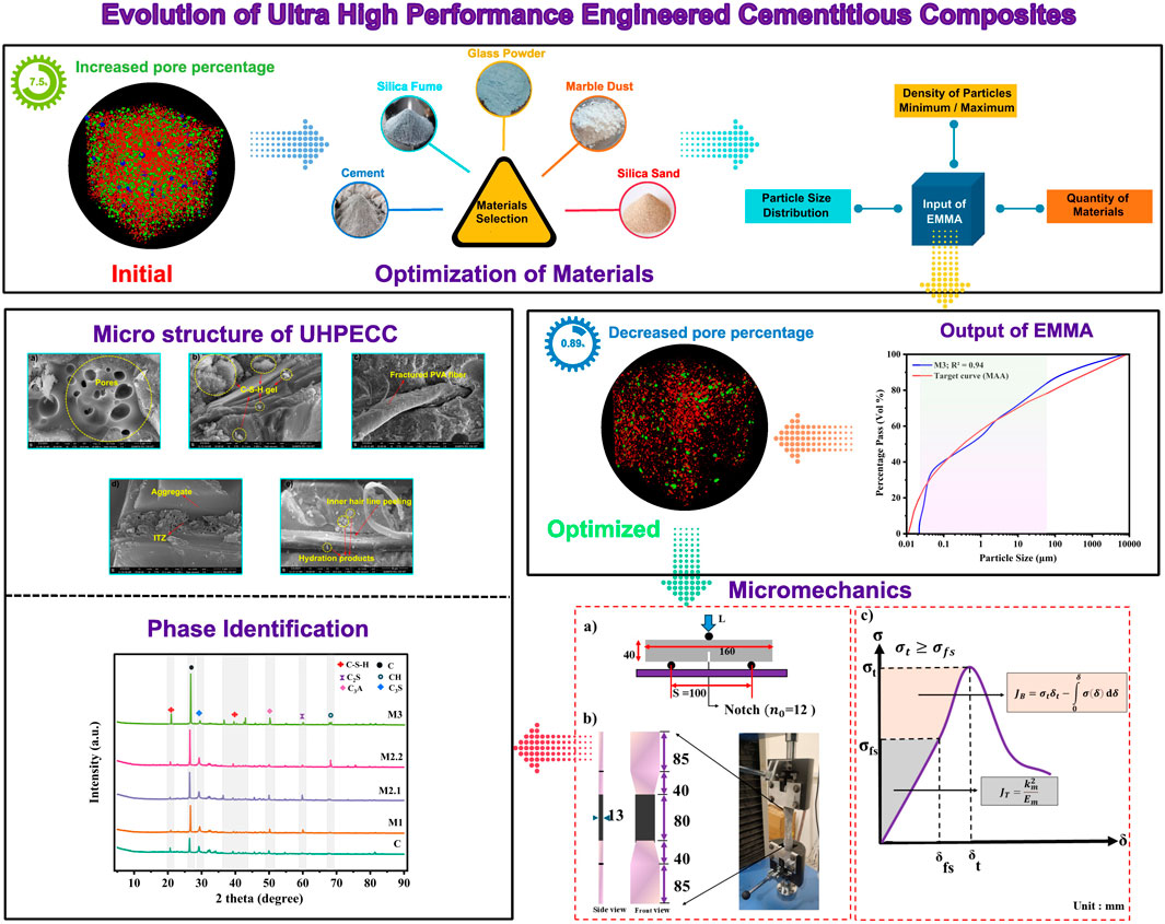
Ultra-high-performance engineered cementitious composites (UHPECC) are becoming increasingly important in modern construction. In this study, the Modified Andreasen and Andersen (MAA) particle packing model was employed to optimize the material proportions required for achieving superior strength and ductility. The effectiveness of the MAA model in achieving a dense matrix was validated through CT scan analysis. Additionally, micromechanics theory was applied to confirm the material design. All UHPECC mixes were evaluated for their crack patterns and strain-hardening behavior. Experimental results demonstrated that a quaternary blend of Supplementary Cementitious Materials (SCMs) significantly improved compressive strength and ultrasonic pulse velocity by up to 48% and 22%, respectively, compared to conventional UHPECC. The addition of 2% PVA fibre increased the strength and energy index by as much as 11% and 60%, respectively. These results help validate the fiber/matrix bonding behavior of UHPECC, which involves incorporating various types of SCM and fibers. The strong correlation between theoretical predictions and experimental outcomes further confirms the reliability of the design approach. Additionally, the microstructure of UHPECC was analyzed using X-ray Diffraction (XRD), Field-Emission Scanning Electron Microscopy (FE-SEM), and Thermogravimetric Analysis (TG).
1 Introduction
1.1 Development and characteristics of ECC and UHPECC
In the 1990s, Professor Victor Li developed Engineered Cementitious Composite (ECC), a contemporary form of cement-based composites. The main goal of ECC was to achieve a strain-hardening behaviour of over 3%, marking a significant advancement over traditional concrete. Figure 1a outlines the research and development network related to cementitious composites. Conventional ECC incorporates cement, fine sand, and either synthetic or steel fibers into the cement matrix. It usually reaches a compressive strength between 60 and 80 MPa, along with tensile and flexural strengths ranging from 3 to 5 MPa. Furthermore, using the Particle Packing Method (PPM) enables the effective filling of voids with fine powders, resulting in a densely packed composite. This enhancement notably improves the overall quality of cementitious composites, paving the way for the creation of Ultra-High-Performance Engineered Cementitious Composites (UHPECC). Researchers design UHPECC to deliver high compressive strength, strain-hardening behaviour, and tensile strength, thereby extending the service life of structures (Fu et al., 2021; Liu et al., 2023). This material finds application in shotcrete, off-site precasting, and the extrusion of structural elements.
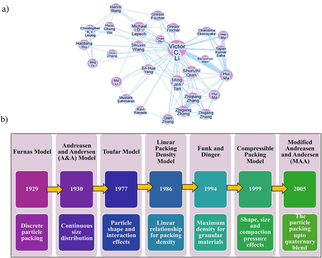
Figure 1. (a) Research network of cementitious composite, (b) Types of PPM used in optimization of cementitious materials.
1.2 Role of supplementary cementitious materials (SCMs)
To achieve the desired behavior of Ultra High-Performance Engineered Cementitious Composites (UHPECC), the meticulous selection of material combinations is essential for forming a dense matrix. Typically, these combinations include Supplementary Cementitious Materials (SCMs) such as glass powder, fly ash, marble dust, slag, iron ore powder, silica fume, silica sand, along with synthetic and steel fibers (Fu et al., 2021; Gou et al., 2023; Liu et al., 2023; Zhang et al., 2023; Wang et al., 2024). The hydration products formed in UHPECC differ from those found in traditional concrete. Specifically, during the hydration process, the presence of water around SCM particles in UHPECC leads to the generation of additional calcium silicate hydrate (C-S-H) gel within the matrix. Recently, K and Om (2024) highlighted the hydration stages of UHPECC, pointing out that incorporating supplementary cementitious materials SCMs. In traditional concrete, where cement serves as the sole binder, monodispersing occurs. In contrast, the use of binary, ternary, and quaternary dispersions through various SCM combinations creates the additional precipitation around the cementitious particle (Zhang et al., 2025). Additionally, a comprehensive review of different types of SCMs used in cementitious compositions and the fundamental principles of particle packing theory has been conducted (Li, n.d.; Liang et al., n.d.; Huang et al., 2021).
1.3 Importance of particle packing method (PPM) in mix optimization
The Particle Packing Method (PPM) plays a crucial role in the mix design of cementitious composites. By utilizing PPM for the dense packing of materials in UHPECC, it significantly reduces material waste compared to traditional trial-and-error approaches in mix design. Specifically, PPM optimizes the ideal volumetric proportions of fillers, binders, and liquid content in the matrix, resulting in improved workability, reduced bleeding, and segregation. Several types of PPM and their associated models are illustrated in Figure 1b. Among these, the Funk and Dinger Model, the Modified Andreasen and Andersen (MAA) Model, and the Linear Packing Density Model are designed to achieve an optimal concrete mix. Notably, the MAA model is effective for particles smaller than 250 µm (Díaz et al., 2021). This model effectively controls the liquid phase within the solid system, enhancing the interaction among the components. For instance, Fan et al. (2022) minimized the pore volume by up to 7.07% through micro-CT scan analysis, utilizing the MAA packing model while adjusting the liquid phase in the matrix. Furthermore, Essam et al. (2023) demonstrated that incorporating waste marble dust into cementitious compositions reduces production costs. Their study employed the MAA model to optimize the quantities of materials, achieving a compressive strength exceeding 80 MPa and reducing the voids ratio up to 0.025.
1.4 Fiber reinforcement and strain-hardening behaviour
Ductility is a critical factor in enhancing the tensile and flexural strength of cementitious composites. To mitigate the brittle nature, incorporating short synthetic fibers into the matrix significantly improves ductile behaviour (Feng et al., 2025). The inclusion of synthetic fibers such as polyvinyl alcohol (PVA), carbon fibers, polyethylene (PE), and polypropylene (PPP) is key to achieving high strain-hardening capacity (SHC) (Zhang et al., 2019; Ghasemzadeh Mousavinejad and Parsa Alemi, 2022). These fibers not only improve energy absorption but also reduce the risk of sudden failure. Notably, PVA fibers are particularly effective in controlling crack widths under tensile loading, typically ranging from 50 to 100 µm. Fu et al. (2021) investigated the mechanical properties and microstructure of ECC that incorporated nano silica (NS), PE fibers, and silica sand with the PPM. Their findings revealed that incorporating 0.45% NS significantly improved packing density and achieved an SHC of 7.4%. Similarly, Huang et al. (2020) demonstrated that a compressive strength of 82.11 MPa and a tensile strength of 8.06 MPa were achieved by using silica sand and a quaternary blend of cementitious materials, including ultrafine fly ash, lime powder, silica fume, and fibers such as PE and steel. This combination resulted in superior mechanical properties and a densely packed microstructure. Furthermore, Shahni Karamzadeh et al. (2024) demonstrated that incorporating 1% NS into cementitious composites containing PE fibers reduced crack widths by up to 59.4%, thereby achieving a strain-hardening capacity of 5%. In another study, Singh et al. (2022) incorporated Stone Slurry Powder (SSL) into ECC mixtures, resulting in a 43.3% reduction in production costs while maintaining excellent mechanical and durability properties. A recent investigation into the abrasion resistance of hybrid fiber reinforcement, which included both steel and PVA fibers with nano-SiO2, demonstrated that the use of hybrid fibers improved abrasion resistance by up to 55.64 (Zhang et al., 2025). Gao et al. (2025) studied the bonding behavior of concrete when using PVA fiber under shear loading conditions, finding that the addition of PVA fiber improved the interface bonding.
1.5 Research significance
Several studies have focused on developing traditional ECC using fly ash, GGBS, metakaolin, and rice husk ash as replacements for cement. Researchers have conducted limited studies on optimizing composites based on the physical and chemical characteristics of materials. This research investigates the significance of particle packing in UHPECC by incorporating SCMs such as Marble Dust Powder (MDP), Glass Powder (GP), and Silica Fume (SF). The optimization process utilized EMMA software, which incorporates the MAA model. Outcomes were confirmed through micro-CT scan analysis to assess pore volume percentage. Additionally, the strength and energy index are validated using micromechanics theory. It is essential to satisfy material design requirements to ensure the successful production of UHPECC. The results of this study provide insights into optimizing the volumetric composition of materials to achieve a dense matrix.
2 Materials and methods
2.1 Properties of materials used in UHPECC
The materials used for developing UHPECC included Ordinary Portland Cement (OPC) Grade 53, which conforms to Indian Standard IS 269. Additionally, Marble Dust Powder (MDP), Silica Fume (SF), and Glass Powder (GP) were utilized, with specific gravities of 3.13, 2.70, 2.20, and 2.40, respectively. The physical and chemical properties of binders are detailed in Table 1. The particle size of the binder was analyzed using a Malvern 2000 laser diffraction analyzer, in accordance with ISO 13320:2020, and the results are presented in Figure 2a. The results of the X-ray diffraction (XRD) examination showed that SF and GP were mainly amorphous. MDP also demonstrated amorphous characteristics and contained a significant amount of Calcium Carbonate (CaCO3), as illustrated in Figure 2b. Additionally, Field Emission Scanning Electron Microscopy (FE-SEM) images of the binders are shown in Figure 2c. The specific surface area of the binders was determined using BET analysis. Silica sand, with a particle size greater than or equal to 300 μm, was employed as the fine aggregate. Polyvinyl Alcohol (PVA) fibers, measuring 8 mm in length and 39 μm in diameter, were incorporated into the mix. These fibers had a modulus of elasticity of 40 GPa and a tensile strength of 1,740 MPa. To achieve the desired workability at various water-to-binder ratios, a High Range Water Reducer (HRWR) based on polycarboxylic ether was added.
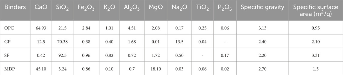
Table 1. The chemical compositions and physical properties of binders.
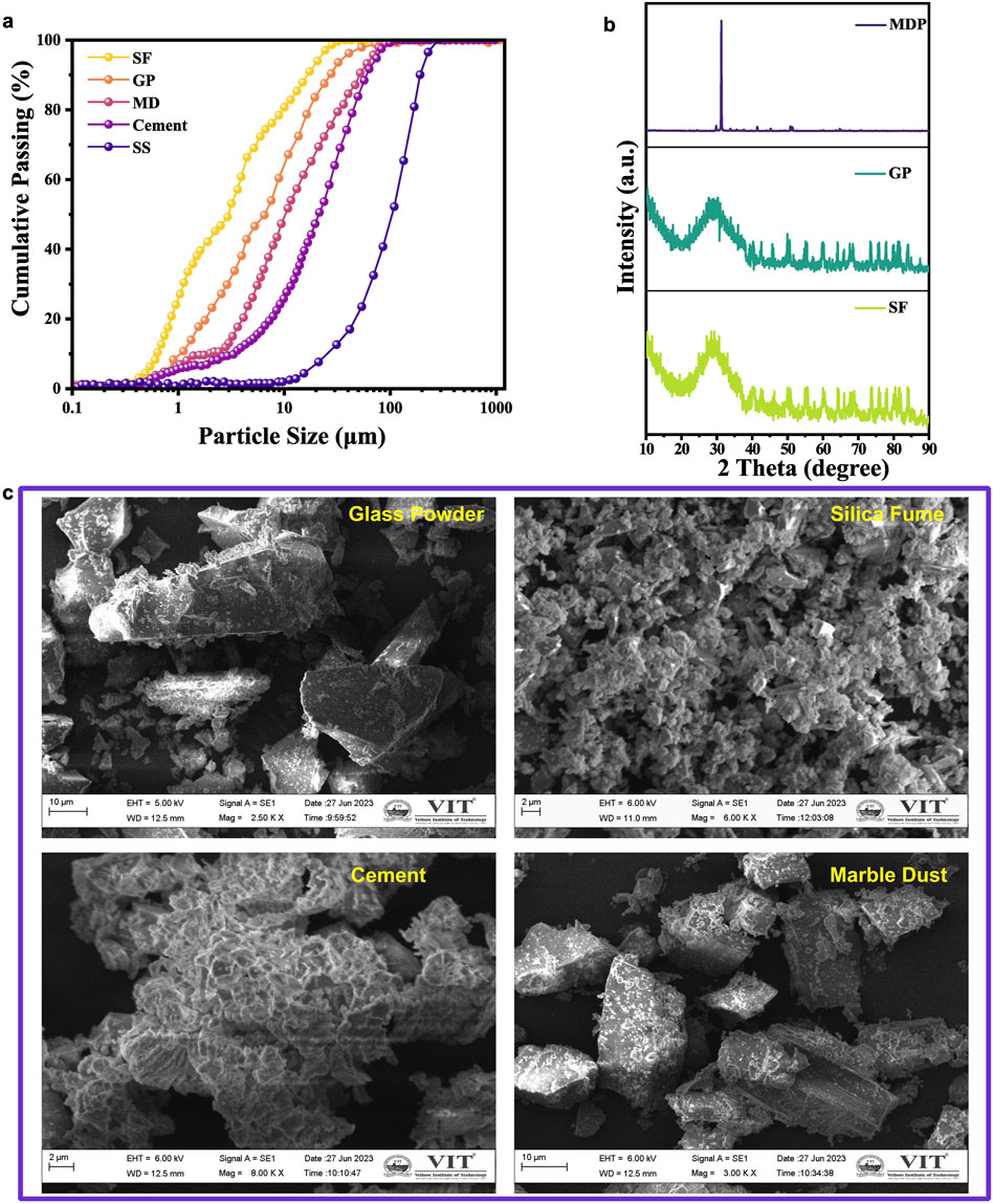
Figure 2. (a) Particle size distribution. (b) X-ray diffraction (XRD) and (c) FE-SEM image of cementitious materials.
2.2 Mix design
The Modified Andreasen and Andersen (MAA) model significantly improves the optimization of fine particles, such as powders and fillers within a matrix (Zhu et al., 2022; Fan et al., 2023; Indhumathi et al., 2024; Tan et al., 2024; Ai et al., 2025). To minimize voids, this packing model aims to tightly arrange particles by combining different sizes (Li, 2003). This research focuses on developing UHPECC using the EMMA mixer analyzer, which incorporates the Modified Andreasen and Andersen (MAA) model. The EMMA mixer analyzer requires the following input parameters: particle density, material quantity, distribution modulus (q), and the minimum and maximum particle sizes. The distribution modulus (q) determines the rheological properties of the mix, ranging from 0.2 to 0.3. A high q value shows coarse grain particles and a less workable mix, whereas a low q value shows fine grain particles and a more workable mix (User Guide Elkem Materials Mixture Analyser-EMMA). Equation 1 presents the MAA equation, utilized for calculating the materials proportion, which is implemented in EMMA:
Where D, Dma, and Dmi represent the average, maximum and minimum particle sizes of the composed material and CPP is the cumulative percentage of particles finer than the D. After determining the optimum mix proportion, the PSD curve of the materials is compared with the target curve. The Least Squares Method (LSM) is used to evaluate the fit. The fitting degree R2 is given in Equation 2. An R2 value nearing one suggests that the PSD curve of the composite material aligns closely with the target curve, indicating dense packing.
The variables Pr and Tc represent the predicted and target cumulative percentages of particles, respectively. After determining the material quantities for UHPECC, the next step is sample preparation.
2.3 Casting and test procedure
Figure 3 illustrates the optimization process that utilizes the EMMA model, along with the sample preparation procedure. The team prepared the fresh UHPECC using a portable high-speed mixer. Initially, all powders and filler materials underwent premixing for 0–3 min to achieve uniform distribution. Then, 75% of the total water content was added to the mix at medium speed. Next, the HRWR and the remaining 25% of water were incorporated into the mixture, followed by the slow introduction of PVA fibers into the blend. A mini flow table test was conducted to evaluate the rheological properties of the fresh mix by ASTM C1856 [26]. As shown in Table 2, the fresh UHPECC was poured into moulds for the mechanical strength test. Following a 24-h casting period, the specimens were moved to a hot water curing chamber. During the initial preheating stage, the temperature increased gradually over 2 h. The specimens were maintained at 90 °C for 8 h before being returned to room temperature. After this hot water curing process, the specimens remained under standard curing conditions until the testing age (Hiremath and Yaragal, 2017; Shi et al., 2020; Xia et al., 2025).
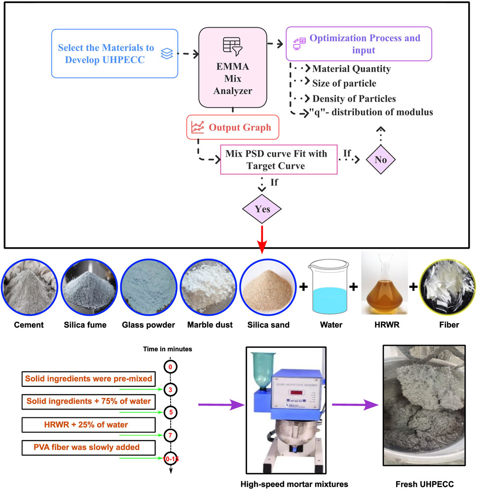
Figure 3. The production process of UHPECC.
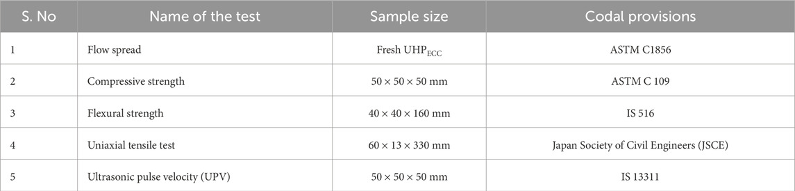
Table 2. Test details for UHPECC.
3 Results and discussion
This study investigated 16 Ultra High-Performance Engineered Cementitious Composites (UHPECC) mixtures that incorporated various combinations of binary, ternary, and quaternary materials. These mixtures were designed based on the particle packing model, as detailed by K and OM (2025). Through an evaluation of fresh properties and compressive strength, five optimal mixes were selected for further analysis. This research specifically examines the ultrasonic pulse velocity, flexural strength, and micromechanical properties of UHPECC mixtures reinforced with Polyvinyl Alcohol (PVA) fibers. Additionally, microstructural characterization was performed using X-ray Diffraction (XRD), Scanning Electron Microscopy (SEM), and Thermogravimetric (TG) analyses.
3.1 Validation of MAA packing model by micro-CT scan
Material properties, such as particle density, maximum particle size, and minimum particle size, must be entered into the EMMA software. The next step is to specify the amounts of each material required to create the PSD curve after developing these properties. To achieve a densely packed matrix, the distribution modulus (q) and material proportions must be adjusted. A traditional UHPECC mix (C) was created in accordance with ASTM C1856, excluding the fibre and SCMs. Four mixtures, including SF, MDP, and GP, were optimized using the EMMA tool by incorporating and adjusting SCMs. M1, M2.1, M2.2, and M3 were the names given to these mixtures. Table 3 lists the ingredient proportions for each mixture.
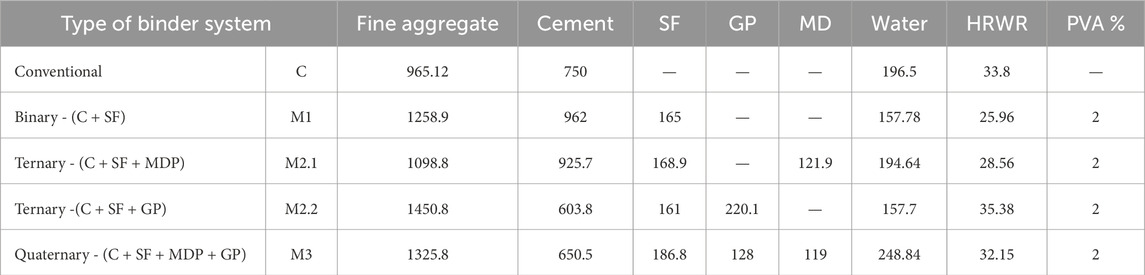
Table 3. Material proportion for UHPECC (kg/m3).
In UHPECC, the arrangement of particles within the matrix plays a crucial role in achieving high performance. A dense particle packing significantly reduces the pore volume of the matrix, enhancing its overall properties. This study examined the reduction in pore volume achieved by the MAA model and validate with the micro-CT scan. Following ASTM 1856, a conventional UHPECC mix (C) was developed without the addition of SF, MDP, and GP. The EMMA tool combined with the MAA model was used to optimise four mixes, which were subsequently named M1, M2.1, M2.2, and M3. The proportions of ingredients for all mixtures are specified in Table 3.
A high pore percentage (PP) of up to 7.5% was the result of the conventional mix (C). Additionally, Figure 4 displays the results of the MAA model for various combinations of cementitious materials. The conventional mix (C) exhibited a high PP of up to 7.5%. Figure 4 displays the results of the MAA model for various combinations of cementitious materials, which include binary, ternary, and quaternary types. These results were validated through pore percentage analysis using micro-computed tomography (micro-CT) scanning. In the graphs, the blue curve represents the Particle Size Distribution (PSD) of the materials. In contrast, the red smooth curve illustrates the ideal arrangement of tightly packed particles based on the input materials. Aligning the material curve with the target curve becomes easier when both the solid materials and the liquid phase (water + HRWR) are modified. For the binary combination of cement and silica fume (SF), referred to as Mix M1, as shown in Figure 4a, the porosity percentage is 4% lower than that of the traditional mix. Figures 4b,c illustrate the ternary combinations of cementitious materials. In comparison to mixes M1 and M2.1, mix M2.2, which consists of cement, SF, and glass powder (GP), demonstrated that the PSD curve was better aligned with the target curve, resulting in a lowered PP of 1.18%. Figure 4d presents the results for the quaternary blend of cement, SF, GP, and MDP. This mixture surpassed both the binary and ternary combinations by achieving the lowest porosity percentage at 0.89%. The following study investigates the mechanical behaviour and fiber-matrix bond characteristics of the optimized mix proportions obtained from the MAA model.
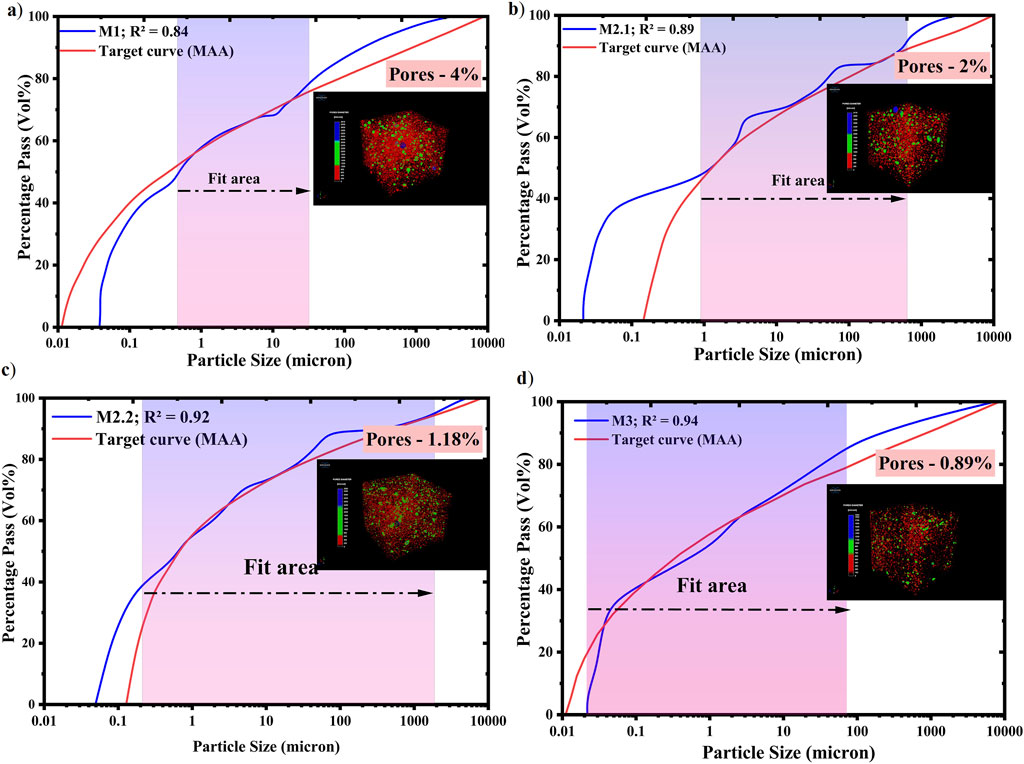
Figure 4. The graphical output from the MAA model: (a) binary mix M1, (b) ternary mix M2.1, (c) ternary mix M2.2, and (d) quaternary mix M3.
3.2 Flow spread measurement
Figure 5 illustrates the flow spread and flow percentage for all UHPECC mixtures. The flow spread values varied from 210 to 240 mm, primarily influenced by the dosage of high range water reducer (HRWR) and binder content. Proper mixing time is essential to prevent particle agglomeration and to ensure uniform fiber distribution. Effective fiber dispersion results in the absence of lump formation and achieves good flow spread in UHPECC.
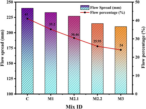
Figure 5. Flow spread vs. flow percentage of UHPECC.
In the mini slump flow test, the results indicated that the addition of supplementary cementitious materials (SCMs) led to a gradual reduction in flow spread compared to the conventional mix. However, all UHPECC mixtures adhered to the flow spread limits set by ASTM C1856. The percentage decrease in flow spread relative to the conventional mix was recorded as 2.9%, 5.41%, 10.41%, and 12.5% for Mixes M1, M2.1, M2.2, and M3. The flow percentage was calculated using Equation 3 (Anbazhagan and Pachaiappan, 2024).
Where
3.3 Mechanical properties
3.3.1 Compressive strength
This study investigates the compressive strength (CS) of UHPECC subjected to hot water curing, incorporating SF, MDP, and GP into the cementitious materials. Curing the mixture in hot water at 90 °C for 8 h accelerates the binder reactions, leading to a stronger bond with the fillers and fibers. This process acts as a pre-treatment before standard curing, significantly enhancing the mechanical properties of the UHPECC. The CS of UHPECC was measured at 7, 14, and 28 days, as depicted in Figure 6a. For each mix, nine specimens were tested to ensure the reliability and accuracy of the CS measurements. Additionally, Figure 6b illustrates the relationship between CS and Ultrasonic Pulse Velocity (UPV) in UHPECC. The correlation between pulse velocity and CS is valuable for assessing the internal quality and compactness of the matrix.
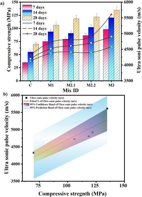
Figure 6. (a) UPV and compressive strength. (b) Correlation between the UPV and compressive strength.
The conventional mix (C) achieved a 28-day CS of 70 ± 4.32 MPa and an ultrasonic pulse velocity (UPV) of 4,328 m/s under combined curing conditions. In comparison, the 28-day compressive strengths for the mixes M1, M2.1, M2.2, and M3 were measured at 105.89 ± 5.91 MPa, 118.5 ± 6.3 MPa, 121.8 ± 6.7 MPa, and 134.72 ± 6.95 MPa, respectively. The corresponding UPV values for these mixes were 4,725 m/s, 4,804 m/s, 4,919 m/s, and 5,612 m/s. A strong correlation was observed between UPV and compressive strength, with an R2 value of 0.92, as shown in Figure 6b. In the binary mix (M1), the addition of 7.8% silica fume (SF) raised the CS to over 100 MPa. In the ternary mixes (M2.1 and M2.2), the incorporation of SF combined with MDP and GP achieved the CS of 60% and 65%, respectively, compared to the conventional UHPECC. The quaternary mix (M3), which included cement, MDP, GP, and SF, achieved the highest CS of 134.72 ± 6.95 MPa among all the tested mixes. During the hydration process, MDP generates a significant amount of calcium hydroxide (CH), similar to that produced by cement. The CH generated by both cement and MDP reacts with the silica present in SF and GP to produce additional C-S-H gel. The ternary mixes contained 8.2% MDP and 11% GP, while the quaternary mix had 7.4% MDP and 9.5% GP. All these modified mixes achieved compressive strengths exceeding 100 MPa and demonstrated excellent UPV values.
Similarly, existing literature suggests that the addition of MDP up to 10% effectively seals the pores. However, exceeding 10% indicates a loss of dilution capacity for MDP ions, which affects the properties of composites (Fu et al., 2021; Liu et al., 2023; Zhang et al., 2023). Furthermore, the UPV measurements for all UHPECC mixtures indicate a high-quality matrix. According to ASTM C597–16, the standard outlines the procedure for calculating the Dynamic Young’s Modulus (DYM) based on UPV value (Test Method for Pulse Velocity Through Concrete, 2016). The results demonstrate that the DYM of UHPECC increases with increases in the UPV values. The DYM for mixes C, M1, M2.1, M2.2, and M3 are 48.15 GPa, 53.72 GPa, 54.15 GPa, 54.91 GPa, and 56.38 GPa, respectively. A gradual increase in DYM is observed compared to the conventional mix.
3.3.2 Flexural strength of UHPECC
Figure 7 illustrates the Flexural Strength (Fs) and Energy Absorption Capacity (EAC) of UHPECC, based on tests performed on nine specimens per mix at 7, 14, and 28 days. The EAC represents the amount of energy absorbed by the material before reaching ultimate failure. In UHPECC, multiple microcracks form and propagate before final fracture, allowing the material to undergo more deformation. This behaviour contributes to higher energy absorption and delays sudden brittle failure. The EAC is calculated as the area under the load-deflection curve obtained during the flexural test.
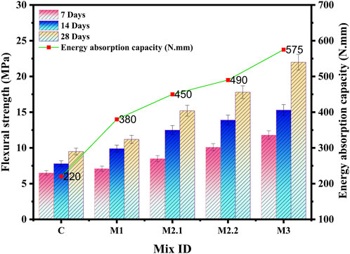
Figure 7. Energy absorption capacity and flexural strength.
Among all the mixtures, UHPECC M3 exhibited the highest Fs and EAC. The quaternary blend of SCMs resulted in a 56% improvement in Fs and a 61.5% gain in EAC compared to conventional UHPECC. The Fs values after 28 days for mixes C, M1, M2.1, M2.2, and M3 were recorded as 9.5 ± 1.22 MPa, 11.2 ± 1.46 MPa, 15.2 ± 2.1 MPa, 17.8 ± 1.89 MPa, and 22 ± 2.3 MPa, respectively. The addition of PVA fiber in UHPECC achieved high EAC and flexibility. Existing studies indicate that the molecular interaction between fibers and SCM ions contributes to an improved load transfer capacity. Additionally, the electrostatic attraction between the polymeric chains and the binder gels increases the bonding properties (Liu et al., 2023). The EAC was determined based on load-displacement data obtained from flexural strength tests on UHPECC specimens, yielding EAC values ranging from 220 to 573 N·mm.
3.3.3 Strain hardening of UHPECC
This study investigates the uniaxial tensile behaviour of UHPECC to evaluate strain-hardening SH characteristics. Material properties such as ductility, quasi-brittleness, and brittleness influence these SH characteristics. The stress-strain curve typically displays three distinct regions based on the matrix response under tensile loading. In the first region, the material shows a linear response as it deforms elastically under increasing load. The following two regions are crucial for determining whether the material is brittle or ductile, particularly in terms of strain hardening and strain softening (Huang et al., 2021). Figures 8a,b detail the strain capacity, tensile strength (Ts), and crack patterns of all mixtures. We recorded the tensile strengths of the UHPECC mixes C, M1, M2.1, M2.2, and M3 as 6.1 ± 3.51 MPa, 9.3 ± 3.9 MPa, 10.1 ± 4.02 MPa, 11.6 ± 4.27 MPa, and 12.3 ± 4.41 MPa with corresponding strain capacities of 3.5%, 5.8%, 6.3%, 8.7%, and 9.5%. To contextualize the effectiveness of the developed UHPECC mixes and highlight advancements over existing materials, it is essential to compare their performance with findings from previous literature.
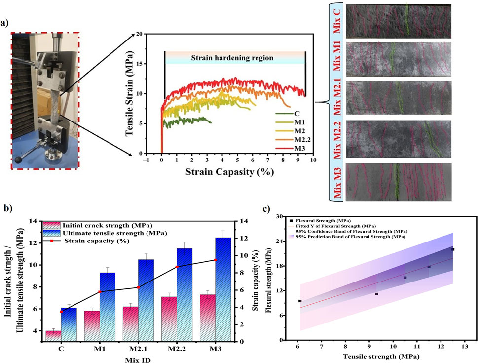
Figure 8. (a) Crack pattern for uniaxial tensile test, (b) Strain capacity and tensile strength, and (c) Correlation between the tensile strength and flexural strength.
For example, Hou et al. (2022) employed a multi-blend of SCMs, including metakaolin, fly ash, lime powder, and silica fume, along with polypropylene (PPP) fibers, achieving a tensile strength of only 3.20 MPa. Researchers attributed this relatively low performance to the hydrophobic nature of PPP fibers, which weakens the bond between the fibers and the matrix. In another study, Li et al. (2024) utilized a binary matrix of fly ash and polyvinyl alcohol (PVA) fibers, which exhibited a tensile strength of 4.53 MPa and a strain capacity of 3%. In contrast, the current study achieved a tensile strength of over 4 MPa even with binary SCM blends. Similarly, Liu et al. (2023) used polyethylene (PE) fibers in combination with silica fume, fly ash, and crumb rubber, reporting a tensile strength of 8.06 MPa and a strain capacity of 2.28%. This research demonstrates improved tensile strength and strain capacity compared to previous studies, indicating that the optimized cementitious matrix and PVA fiber reinforcement work effectively together. The experimental results established a strong correlation between flexural strength and tensile strength, as shown in Figure 8c. The coefficient of determination (R2) measures 0.96, indicating a high level of reliability between the flexural and tensile strengths.
3.3.4 Micromechanics theory
Micromechanics theory is essential for developing UHP-ECC for structural applications, as it bridges the gap between materials science and engineering performance. Traditional concrete design typically depends on empirical methods at the macroscale, which fail to account for the interactions between fibers and matrix. By applying this theory, engineers can tailor UHPECC to meet specific structural requirements, ensuring safety, durability, and cost-effectiveness for sustainable infrastructure. Li (2003) extensively discussed fiber bridging and interface behaviour in composites, emphasizing the importance of micromechanics in validating material design for structural applications. Similarly, Shim et al. (2021) demonstrated a practical design approach for achieving strain-hardening properties in building structures. Their study evaluated the energy and strength indices for first crack formation and final fracture, resulting in high strain-hardening behavior. Figure 9 illustrates the analysis of the fiber-matrix interface bond through micromechanics.
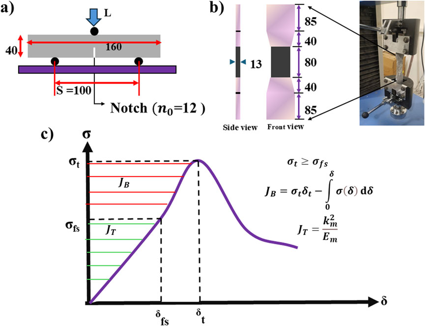
Figure 9. (a) The test setup of the three-point bending test for the specimen. (b) The uniaxial tensile test for the dog bone specimen. (c) Describes the fibre-matrix mechanism.
In Equations 4 and 5, the strength parameter SHs is defined by
Table 4 presents the factors that influence the micromechanics for calculating the strength parameter and energy parameters. The incorporation of PVA fibers resulted in a high Young’s modulus of UHPECC from 34.23 to 42.57 GPa. The high Young’s modulus of UHPECC positively contributed to load-bearing capacity, crack control, and fiber-matrix bridging. The strength parameter, quantified as the strength index, is recommended to exceed 1.3. All UHPECC mixtures achieved a strength index greater than 1.3. Notably, the introduction of MDP and GP with SF into the cement matrix further increased the strength index up to 1.71.
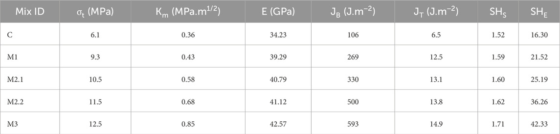
Table 4. Output for SHS and SHE.
Additionally, Equation 10 represents the linear correlation between ultimate tensile strength and the strength parameter. As illustrated in Figure 10a, the tensile strength exhibited a positive trend with the strength index, with a coefficient of correlation (R2) of 0.98.
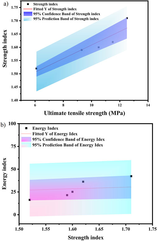
Figure 10. (a) Correlation between ultimate tensile strength and strength index. (b) Correlation between strength index and energy index.
Furthermore, the validation of the energy index depends on fiber-matrix bridging energy and fracture energy of UHPECC. The value indicates the energy absorbed when a fracture first appears in the matrix as a result of increasing loading. This value is directly proportional to the initial strain capacity of UHPECC. The fiber bridging energy varied from 106 to 593 J·m2. The total energy index must be greater than 3 (Zhou et al., 2019). All UHPECC mixtures achieved a strength and energy index greater than the specified limits. The experimental results, validated through micromechanics theory, strongly confirm the reliability of the material design. Furthermore, Equation 11 demonstrates a strong linear correlation between the strength index and energy index, with an R2 value of 0.94, shown in Figure 10b. The experimental results regarding the strength and energy index have been validated by existing literature. Xu et al. (2022) investigated the incorporation of polyethylene (PE) and steel fibers into cementitious compositions, achieving strength and energy indices of 1.45 and 8.6, respectively. Furthermore, Yu et al. (2017), Zhou et al. (2019), and Wu et al. (2022) examined the energy absorption behavior of synthetic fibers, as well as a hybrid of synthetic and steel fibers. This current study evaluates polyvinyl alcohol (PVA) fiber, which has demonstrated higher energy and strength index compared to those in earlier research.
4 Microstructure characteristics of UHPECC
4.1 FE-SEM
Field Emission Scanning Electron Microscopy (FE-SEM) analysis was conducted to examine the microstructure of the UHPECC matrix and assess the effects of SCMs and PVA fibers, as shown in Figure 11. The FE-SEM analysis enabled the identification of various microstructures, including pores, Calcium-Silicate-Hydrate (C-S-H) phases, the Interfacial Transition Zone (ITZ), and fiber fracture patterns.
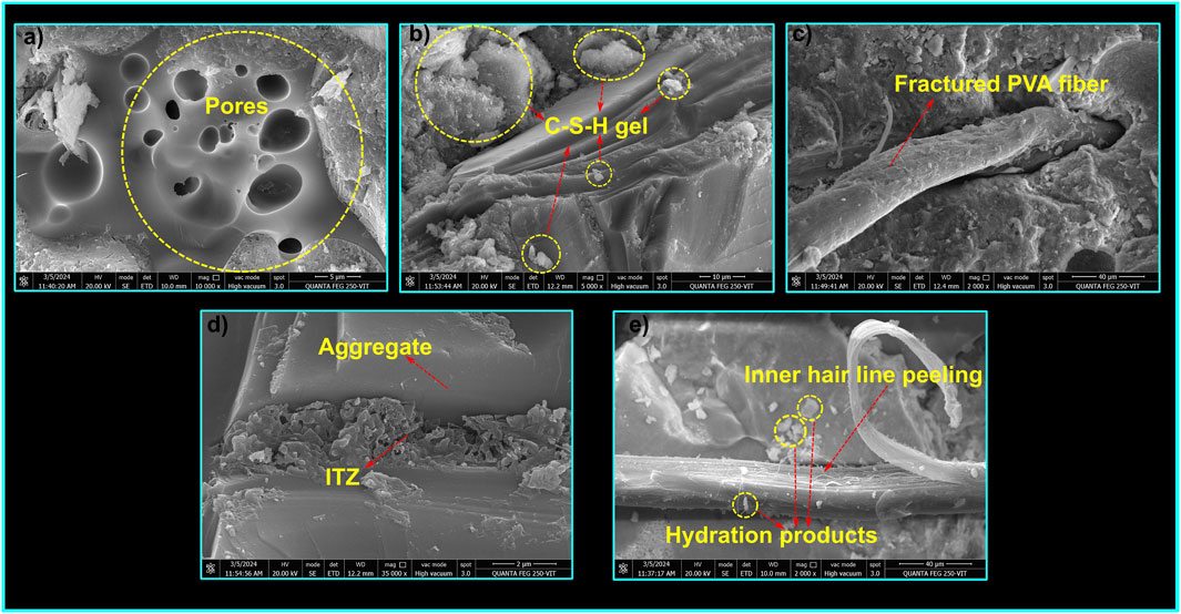
Figure 11. FE-SEM image of UHPECC: (a) conventional mix C, (b) quaternary mix M3, (c,e) type of fibre fracture, (d) ITZ of UHPECC.
Figure 11a depicts the microstructure of the conventional UHPECC mix (C), highlighting the presence of pore clusters near the aggregate-paste interface. These pores suggest inadequate particle packing, which is likely due to the absence of SCMs in the conventional UHPECC matrix. Conversely, the inclusion of SCMs such as SF, GP, and MDP resulted in a denser microstructure. Figure 11b illustrates the densified matrix achieved through the quaternary blending of SCMs, characterized by an increased presence of C-S-H phases. The hot water curing method used for UHPECC promotes the pozzolanic reactions between calcium hydroxide (CH) and silica in the SCMs, leading to the formation of softer C-S-H phases. Figure 11d shows the development of a strong ITZ within the UHPECC matrix. The thin layer surrounding the aggregates acts as a protective barrier, restricting the chlorides and sulphates from entering the matrix. Furthermore, Figures 11c,e depict the fiber failure patterns under loading conditions. During loading, the PVA fibers exhibited a pull-out behaviour from the matrix, resulting in hairline peeling without any crack formation near the matrix. Additionally, hydration products were observed on the surface of the PVA fibers, and no fiber agglomeration was detected, indicating that the fibers were effectively dispersed during the mixing process. Based on the FE-SEM analysis, it can be concluded that the incorporation of SCMs facilitates the formation of C-S-H gel.
4.2 Phase identification for UHPECC
The X-ray Diffraction (XRD) technique was used to identify the phases present in hardened UHPECC. Figure 12 presents the XRD pattern of five hardened UHPECC samples, highlighting the crystalline phases observed, including Calcium Silicate Hydrate (C-S-H), Calcite (C), Tricalcium Silicate (C3S), Calcium Hydroxide (CH), Tricalcium Aluminate (C3A), and Tobermorite. Notably, the peak intensity for unhydrated C3S and C2S particles significantly decreased in mix M3, specifically at 2θ values of 29.310° and 59.15°. The first diffraction peak observed at 20.71° in all samples is attributed to the nucleation effects of CH and silica components. A strong intensity for this peak was especially noted in mixes M2.2 and M3. Additionally, the use of hot water curing in UHPECC accelerated secondary hydration, particularly improving the reaction between the extra silica components from SCMs and the CH present in both the cement and MDP. This subsequent reaction of the C-S-H gel with C2S resulted in the formation of Tobermorite, as confirmed by the characteristic spectral range of 36–49. Furthermore, X-ray fluorescence (XRF) spectroscopy was utilized to determine the clinker phase composition in the UHPECC samples. Table 5 details the quantities of Bogue’s components calculated using Bogue’s equations (Shim et al., 2021). The primary elemental composition identified in UHPECC comprised 54%–58% SiO2, 23%–29% CaO, 4%–6% Al2O3, 2.5%–3% Fe2O3, and 1%–2% K2O, which were consistently observed in all UHPECC samples.
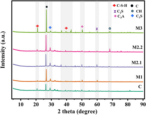
Figure 12. Phase identification by XRD.
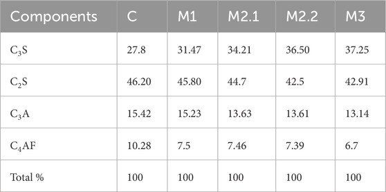
Table 5. Cementicious composition for UHPECC.
4.3 TG/DSC
Figures 13, 14 illustrate the Thermogravimetric Analysis (TG) and Differential Scanning Calorimetry (DSC) analysis curves, depicting the mass loss at different phases of the binder system. The validation of TG and DSC is based on the mass loss observed at elevated temperatures in the UHPECC binder composition. The mass reduction occurs in two primary phases: the amorphous and crystalline structures (Liu et al., 2024). The amorphous structure predominantly consists of C-S-H gel, while the crystalline phase contains CH and calcite, which are present in the matrix. Based on the thermal peaks, the decomposition of the amorphous phase occurs between 30 °C and 450 °C.
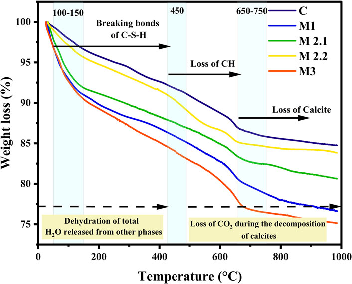
Figure 13. TG for UHPECC.
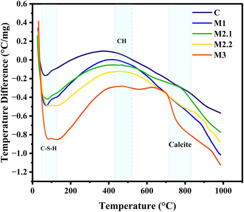
Figure 14. DSC for UHPECC.
The TG/DSC curves of five samples indicate that the first peak appears within the range of 100 °C–120 °C, corresponding to the elimination of free water molecules and the initial breakdown of the C-S-H gel in the matrix. Among all UHPECC mixes, mix M3 exhibits the strongest peak within this temperature range, suggesting a higher initial mass loss due to the decomposition of C-S-H gel and tobermorite compared to other mixes. In the temperature range of 200 °C–400 °C, calcium hydroxide (CH), calcite, and other hydration products surrounding the binder particles lost their stability. The decomposition of crystalline phases such as CH and calcite begins above 400 °C. The TG/DSC curves indicate that mixes M1, M2.1, and M2.2 exhibit similar peak patterns, whereas mix M3 shows distinct peaks at approximately 450 °C and 750 °C, corresponding to the decomposition of CH and calcite structures. The TG/DSC analysis further confirms that mix M3 resulted in higher initial mass loss than the other mixes, indicating a greater formation of C-S-H gel within the UHPECC matrix. Additionally, the TG/DSC results validate the extent of CO2 capture, as calculated using Equation 12 for all UHPECC specimens and illustrated in Figure 15.
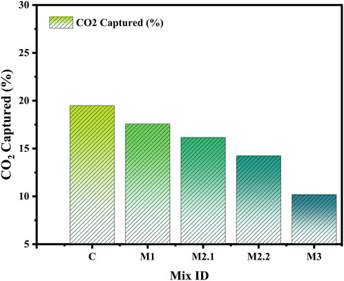
Figure 15. CO2 captured in percentage.
The decomposition of CO2 predominantly occurs above 450 °C (Neves Junior et al., 2019). This study reveals that low CO2 capture is achieved through the incorporation of SCMs in the cementitious mixtures, as compared to conventional UHPECC.
5 Hydration of SCMs in UHPECC
The pozzolanic activity of SCMs significantly enhances the performance of UHPECC while also contributing to a reduction in CO2 emissions. In this study, the incorporation of SF and GP both rich in amorphous siliceous content promotes secondary reactions with calcium hydroxide (CH) which is a crystalline byproduct of cement hydration, resulting in the formation of additional calcium silicate hydrate (C–S–H) gel. The siliceous components in glass powder react gradually with calcium hydroxide (CH), which is why employing hot water curing facilitates the acceleration of the pozzolanic reaction. Additionally, inorganic mineral additives such as MDP, SF, and GP help transition the microstructure from a heterogeneous to a more homogeneous matrix by facilitating balanced ion nucleation and enhancing hydration kinetics. Specifically, the calcium carbonate (CaCO3) present in MDP reacts with the tricalcium aluminate (C3A) phase of cement to form carboaluminate hydrate (C4ACH11), which contributes to early setting and stabilizes the hydration process. The incorporation of a high range water reducer (HRWR) based on polycarboxylate ether (PCE) further improves the workability of the mix. The PCE molecules adhere to the surfaces of cement and SCM particles, creating electrostatic and steric repulsive forces that prevent particle agglomeration and promote improved dispersion.
6 Study limitations and cost analysis
This study successfully develops UHPECC with excellent mechanical strength, strain-hardening capacity, and ductility. However, important to acknowledge certain limitations. One of the primary challenges is achieving uniform fiber dispersion, particularly with synthetic fibers such as PVA. A higher amount of cementitious material with fibers tends to clump during mixing, especially under low w/b ratios, which affects matrix homogeneity and workability. To overcome this issue, gradually increasing the mixing speed helps ensure uniform dispersion of fibers. Additionally, optimizing the mix using the Particle Packing Method (PPM) requires precise control over particle size input and material quantities. Deviation from the target curve can result in either excessive or insufficient binder use, which affects both performance and cost efficiency. We conducted a detailed cost analysis in conjunction with a performance evaluation to assess the economic viability of UHPECC production. The unit costs of each material (in USD/kg) were considered to estimate the total production cost in USD/m3, as summarized in Table 6.
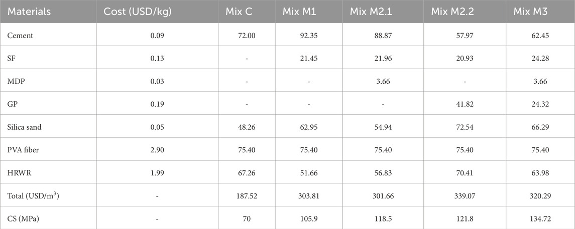
Table 6. Cost analysis of UHPECC (USD/m3).
The manufacturing cost of UHPECC typically ranges from 500 to 600 USD/m3 due to its substantial use of powder content and steel fibers. This research achieved a cost of 303–320 USD/m3 by using locally available materials without compromising strength. The addition of MDP in UHPECC production reduces production costs. The addition of MDP in the quaternary mix reduced the 15% cost and also achieved a strength of more than 130 MPa. The Cost Efficiency Index (CEI), expressed in USD/MPa/m3, was determined for each UHPECC mix (Shah et al., 2022). The CEI values ranged from 2.6 to 2.3 USD/MPa/m3. Mix M3 achieved the lowest CEI of 2.3 USD/MPa/m3, indicating the most cost-effective formulation and making it a suitable choice for UHPECC production in terms of both performance and economic viability.
7 Conclusion
This study investigates the fresh and mechanical properties of UHPECC and evaluates material design using micromechanics theory and 3D pore structure analysis via CT scanning. It also examines the phase composition and microstructure of the hardened UHPECC through XRD, XRF, FE-SEM, and TG/DSC techniques.
Based on the results, the following conclusions were drawn:
• The traditional ultra-high performance engineered cementitious composite (UHPECC) mix design was revised using a particle packing model. To create a densely packed matrix, a multi-blend of cementitious materials was used in optimum quantity.
• Utilizing locally available materials, such as GP, SF, and MDP, enhances the mechanical properties and ductility, as demonstrated in this research. This approach supports construction practices for infrastructure.
• Micromechanics validation ensures that synthetic fiber-reinforced UHPECC achieves ductility and meets the design specifications.
• CT scan analysis confirmed that the inclusion of SCMs reduced the total pore volume in UHPECC by 88%.
• Phase identification analyses using XRD, TG, and FE-SEM confirmed the presence of C-S-H gel, Tobermorite, and calcium hydroxide (CH).
8 Implications of structure and future scope
• Selecting appropriate materials is important for the development of UHPECC. Utilizing locally sourced materials and industrial by-products in the cementitious matrix promotes sustainability.
• Most researchers have focused on replacing cement with SCMs; however, substituting potable water with waste or recycled water in concrete production is another eco-friendly approach that supports sustainable construction practices.
• The composite structural system of steel and UHPECC can significantly reduce maintenance needs in bridge structures. Moreover, evaluating the joint performance of precast bridge deck panels connected with field-cast UHPECC under both static and dynamic loading is important for ensuring structural continuity, efficient load transfer, and long-term serviceability.
• There is a need to scale up UHPECC mixes formulated at the laboratory scale by incorporating various SCMs into full-scale manufacturing processes, bridging the gap between research and practical application.
• UHPECC facilitates the acceleration of project timelines, promotes product accuracy, reduces labour requirements, ensures safety in construction, and minimizes construction waste.
• The self-consolidating properties of UHPECC enhance its applicability in field casting, enabling efficient placement in densely reinforced sections and complex geometries without vibration.
Data availability statement
The original contributions presented in the study are included in the article/supplementary material, further inquiries can be directed to the corresponding author.
Author contributions
KP: Conceptualization, Data curation, Formal Analysis, Investigation, Methodology, Project administration, Software, Supervision, Validation, Visualization, Writing – original draft, Writing – review and editing. OS: Investigation, Methodology, Supervision, Validation, Writing – review and editing.
Funding
The author(s) declare that no financial support was received for the research and/or publication of this article.
Conflict of interest
The authors declare that the research was conducted in the absence of any commercial or financial relationships that could be construed as a potential conflict of interest.
Generative AI statement
The author(s) declare that no Generative AI was used in the creation of this manuscript.
Any alternative text (alt text) provided alongside figures in this article has been generated by Frontiers with the support of artificial intelligence and reasonable efforts have been made to ensure accuracy, including review by the authors wherever possible. If you identify any issues, please contact us.
Publisher’s note
All claims expressed in this article are solely those of the authors and do not necessarily represent those of their affiliated organizations, or those of the publisher, the editors and the reviewers. Any product that may be evaluated in this article, or claim that may be made by its manufacturer, is not guaranteed or endorsed by the publisher.
References
Ai, J., Qiu, K., Yang, B., Peng, S., Zhang, Q., and Jiang, J. (2025). Research on the effects of the water–binder ratio and fiber content on the tensile and bending mechanical properties of ECCs. Materials 18, 509. doi:10.3390/ma18030509
Anbazhagan, P., and Pachaiappan, T. (2024). Improving concrete structures with engineered cementitious composites and kevlar sheets: an affordable retrofitting solution for earthquake resistance. Mater Res. Express 11, 115305. doi:10.1088/2053-1591/ad8ff7
Díaz, J., Gálvez, J. C., Alberti, M. G., and Enfedaque, A. (2021). Achieving ultra-high performance concrete by using packing models in combination with nanoadditives. Nanomaterials 11, 1414. doi:10.3390/nano11061414
EMMA (n.d.). EMMA user guide version 1 user guide elkem materials mixture analyser-EMMA. Available online at: www.elkem.com.
Essam, A., Mostafa, S. A., Khan, M., and Tahwia, A. M. (2023). Modified particle packing approach for optimizing waste marble powder as a cement substitute in high-performance concrete. Constr. Build. Mater 409, 133845. doi:10.1016/j.conbuildmat.2023.133845
Fan, D., Tian, W., and Yu, R. (2022). Incorporation of liquid phase into solid particle packing model for precise design of low water/binder cement-based composites (LW/B-CC): modelling and experiments. Compos B Eng. 242, 110070. doi:10.1016/j.compositesb.2022.110070
Fan, D., Zhu, J., Fan, M., Lu, J. X., Chu, S. H., Dong, E., et al. (2023). Intelligent design and manufacturing of ultra-high performance concrete (UHPC) – a review. Constr. Build. Mater 385, 131495. doi:10.1016/j.conbuildmat.2023.131495
Feng, Z., Zhang, P., Guo, J., Zheng, Y., and Hu, S. (2025). Single and synergistic effects of nano-SiO2 and hybrid fiber on rheological property and compressive strength of geopolymer concrete. Constr. Build. Mater 472, 140945. doi:10.1016/j.conbuildmat.2025.140945
Fu, C., Guo, R., Lin, Z., Xia, H., Yang, Y., and Ma, Q. (2021). Effect of nanosilica and silica fume on the mechanical properties and microstructure of lightweight engineered cementitious composites. Constr. Build. Mater 298, 123788. doi:10.1016/j.conbuildmat.2021.123788
Gao, Z., Zhang, P., Dai, X., Zheng, Y., and Feng, H. (2025). Assessment of bonding behavior of hybrid fiber alkali-activated concrete for tunnel lining concrete restoration. J. Clean. Prod. 514, 145803. doi:10.1016/j.jclepro.2025.145803
Ghasemzadeh Mousavinejad, S. H., and Parsa Alemi, M. (2022). Micro-structural and mechanical properties of PVA fiber reinforced engineered cementitious composite incorporating natural and artificial pozzolanic materials under different temperatures. Constr. Build. Mater 346, 128180. doi:10.1016/j.conbuildmat.2022.128180
Gou, H., Sofi, M., Zhang, Z., Zhu, M., and Mendis, P. (2023). Matrix design and performance development of eco-friendly high-strength, lightweight engineered cementitious composites. J. Build. Eng. 77, 107254. doi:10.1016/j.jobe.2023.107254
Hiremath, P. N., and Yaragal, S. C. (2017). Effect of different curing regimes and durations on early strength development of reactive powder concrete. Constr. Build. Mater 154, 72–87. doi:10.1016/j.conbuildmat.2017.07.181
Hou, M., Zhang, D., and Li, V. C. (2022). Crack width control and mechanical properties of low carbon engineered cementitious composites (ECC). Constr. Build. Mater 348, 128692. doi:10.1016/j.conbuildmat.2022.128692
Huang, B. T., Wu, J. Q., Yu, J., Dai, J. G., and Leung, C. K. (2020). High-strength seawater sea-sand engineered cementitious composites (SS-ECC): mechanical performance and probabilistic modeling. Cem. Concr. Compos 114, 103740. doi:10.1016/j.cemconcomp.2020.103740
Huang, B. T., Weng, K. F., Zhu, J. X., Xiang, Y., Dai, J. G., and Li, V. C. (2021). Engineered/strain-hardening cementitious composites (ECC/SHCC) with an ultra-high compressive strength over 210 MPa. Compos. Commun. 26, 100775. doi:10.1016/j.coco.2021.100775
Indhumathi, S., Umamaheswari, S., Dinesh, A., and Pichumani, M. (2024). Validating synergistic effects of hybrid nanomaterials and progressive collapse behaviour of UHPC beams: do particle packing theory, experiments and finite element analysis strongly interconnected? Sustain. Mater. Technol. 41, e01044. doi:10.1016/j.susmat.2024.e01044
K, P., and Om, S. (2024). A review on the influence of particle packing theory and materials on characteristics of ECC. J. Build. Eng. 98, 111079. doi:10.1016/j.jobe.2024.111079
K, P., and Om, S. (2025). Optimizing UHPECC properties using MAA-based particle packing techniques with SCMs. Front. Built Environ. 11, 1588145. doi:10.3389/fbuil.2025.1588145
Li, V. C. (2003). On engineered cementitious composites (ECC) A review of the material and its applications.
Li, L., Chen, H., Yu, H., Ma, H., Fan, H., Chen, X., et al. (2024). A sawtooth constitutive model describing strain hardening and multiple cracking of ECC under uniaxial tension. Rev. Adv. Mater. Sci. 63, 20240048. doi:10.1515/rams-2024-0048
Li, V. C. (n.d.). Engineered cementitious composites (ECC)-tailored composites through micromechanical modeling.
Liang, L., Lu, X., Ding, Y., Yu, J., Yu, K., and Li, V. C. (n.d.). Design mechanism and multi-scale model establishment of high-modulus engineered cementitious composites. Available online at: https://ssrn.com/abstract=4756061.
Liu, D., Yu, J., Qin, F., Zhang, K., and Zhang, Z. (2023). Mechanical performance of high-strength engineering cementitious composites (ECC) with hybriding PE and steel fibers. Case Stud. Constr. Mater. 18, e01961. doi:10.1016/j.cscm.2023.e01961
Liu, D., Zhang, Z., Wang, S., Abdalla, J. A., Hawileh, R. A., Zhong, J., et al. (2024). Microstructure and mechanical properties of engineered cementitious composites (ECC) with recycling extracted titanium tailing slag (ETTS). J. Build. Eng. 98, 111282. doi:10.1016/j.jobe.2024.111282
Neves Junior, A., Dweck, J., Filho, R. D. T., Ellis, B., and Li, V. (2019). Determination of CO2 capture during accelerated carbonation of engineered cementitious composite pastes by thermogravimetry. J. Therm. Anal. Calorim. 138, 97–109. doi:10.1007/s10973-019-08210-y
Shah, H. A., Yuan, Q., and Photwichai, N. (2022). Use of materials to lower the cost of ultra-high-performance concrete – a review. Constr. Build. Mater 327, 127045. doi:10.1016/j.conbuildmat.2022.127045
Shahni Karamzadeh, N., Karimi, H. R., and Khedri, E. (2024). An investigation on the application of acrylic resin agent for fiber/matrix bond strengthening in green engineered cementitious composites (ECC). Case Stud. Constr. Mater. 20, e03355. doi:10.1016/j.cscm.2024.e03355
Shi, J., Liu, B., He, Z., Wu, X., Tan, J., Chen, J., et al. (2020). Properties evolution of high-early-strength cement paste and interfacial transition zone during steam curing process. Constr. Build. Mater 252, 119095. doi:10.1016/j.conbuildmat.2020.119095
Shim, S. H., Lee, T. H., Yang, S. J., Noor, N. B. M., and Kim, J. H. J. (2021). Calculation of cement composition using a new model compared to the bogue model. Materials 14, 4663. doi:10.3390/ma14164663
Singh, M., Saini, B., and Devidas, C. H. (2022). Effect of stone slurry powder waste and low-cost fibers on strength, electrical resistivity, permeability, and ecological performance of engineered cementitious composite. Arabian J. Geosciences 15, 1727. doi:10.1007/s12517-022-11018-0
Tan, Y., Li, B., Chen, Y. T., Ling, Y., and Shi, W. (2024). Effects of superabsorbent polymer and natural zeolite on shrinkage, mechanical properties, and porosity in ultra-high performance concretes. Dev. Built Environ. 20, 100568. doi:10.1016/j.dibe.2024.100568
Test Method for Pulse Velocity Through Concrete (2016). Test method for pulse velocity through concrete. doi:10.1520/C0597-16
Wang, P., Cheng, Z., Jia, X., Pan, J., and Zhou, J. (2024). Strategies for reusing multiple recycled powders: evaluating the mechanical performance and sustainability of engineered cementitious composites (ECC). Constr. Build. Mater 447, 138131. doi:10.1016/j.conbuildmat.2024.138131
Wu, J. D., Guo, L. P., Cao, Y. Z., and Lyu, B. C. (2022). Mechanical and fiber/matrix interfacial behavior of ultra-high-strength and high-ductility cementitious composites incorporating waste glass powder. Cem. Concr. Compos 126, 104371. doi:10.1016/j.cemconcomp.2021.104371
Xia, D., Liu, H., and Liang, X. (2025). Effect of curing regimes on mechanical properties and microstructure of ultra-high performance concrete with full Aeolian sand. Constr. Build. Mater 472, 140812. doi:10.1016/j.conbuildmat.2025.140812
Xu, S. L., Xu, H. L., Huang, B. T., Li, Q. H., Yu, K. Q., and Yu, J. T. (2022). Development of ultrahigh-strength ultrahigh-toughness cementitious composites (UHS-UHTCC) using polyethylene and steel fibers. Compos. Commun. 29, 100992. doi:10.1016/j.coco.2021.100992
Yu, K., Wang, Y., Yu, J., and Xu, S. (2017). A strain-hardening cementitious composites with the tensile capacity up to 8%. Constr. Build. Mater 137, 410–419. doi:10.1016/j.conbuildmat.2017.01.060
Zhang, Z., Yuvaraj, A., Di, J., and Qian, S. (2019). Matrix design of light weight, high strength, high ductility ECC. Constr. Build. Mater 210, 188–197. doi:10.1016/j.conbuildmat.2019.03.159
Zhang, Z., Li, Z., He, J., and Shi, X. (2023). High-strength engineered cementitious composites with nanosilica incorporated: mechanical performance and autogenous self-healing behavior. Cem. Concr. Compos 135, 104837. doi:10.1016/j.cemconcomp.2022.104837
Zhang, P., Wang, W., Guo, J., and Zheng, Y. (2025). Abrasion resistance and damage mechanism of hybrid fiber-reinforced geopolymer concrete containing nano-SiO2. J. Clean. Prod. 494, 144971. doi:10.1016/j.jclepro.2025.144971
Zhou, Y., Xi, B., Sui, L., Zheng, S., Xing, F., and Li, L. (2019). Development of high strain-hardening lightweight engineered cementitious composites: design and performance. Cem. Concr. Compos 104, 103370. doi:10.1016/j.cemconcomp.2019.103370
Keywords: MAA model, micromechanics theory, crack pattern, fiber, strength criteria, energy criteria
Citation: Priyanka K and Suganya OM (2025) Behaviour of PVA fiber and SCM-modified UHPECC: a micromechanics approach. Front. Built Environ. 11:1639590. doi: 10.3389/fbuil.2025.1639590
Received: 02 June 2025; Accepted: 19 August 2025;
Published: 03 September 2025.
Edited by:
Hindavi Gavali (Tikate), NICMAR University Pune, IndiaReviewed by:
Amir Ali Shahmansouri, Washington State University, United StatesPeng Zhang, Zhengzhou University, China
Copyright © 2025 Priyanka and Suganya. This is an open-access article distributed under the terms of the Creative Commons Attribution License (CC BY). The use, distribution or reproduction in other forums is permitted, provided the original author(s) and the copyright owner(s) are credited and that the original publication in this journal is cited, in accordance with accepted academic practice. No use, distribution or reproduction is permitted which does not comply with these terms.
*Correspondence: O. M. Suganya, b21zdWdhbnlhQHZpdC5hYy5pbg==