 Kepa Iturralde1,2,3*
 Wenlan Shen3
 Renzo Bazan3Oscar Amo-Grau3
 Danya Liu1,3Aravind Srinivasaragavan1,3Samanti Das3
 Thomas Bock3Christoph Holst1
- 1Chair of Engineering Geodesy, Technical University of Munich, Munich, Germany
- 2Chair of Digital Transformation in Construction, Institute of Construction Management, Faculty of Civil and Environmental Engineering, University of Stuttgart, Stuttgart, Germany
- 3Chair of Building Realization and Robotics, Technical University of Munich, Munich, Germany
The drive towards enhanced efficiency, precision, and automation in the realm of building façade renovation is a salient factor in this paradigm shift. This transition is characterized by the need for streamlined processes that encompass design, fabrication, and installation. This paper expounds upon an integrated workflow that combines data acquisition, geometric modeling, and robotic assembly to automate the manufacturing of prefabricated facade modules for building renovation. The workflow consists of several steps. First, a structured online data acquisition platform has been developed to standardize the digital modeling process, providing users with a guided approach from basic project input to BIM (Building Information Modeling) -compatible outputs. Next, to enhance the precision of facade modeling from the previous step, a geometry estimation method based on AprilTag is utilized. This method facilitates sub-millimeter accuracy through photogrammetric calibration and plane fitting. These geometric definitions are subsequently transferred to a CAM (computer-assisted manufacturing) pipeline, which enables automated detailing and fabrication of panels using industry-standard software. The final step involves robotic assembly driven by a robotic manipulator with a vision-assisted system for flexible pick-and-place operations. The system demonstrated sub-centimeter assembly precision and reduced manual layout and clash-checking time in different case studies. The proposed system offers a scalable and precise solution for energy-efficient building renovation through a seamless connection between digital modeling and robotic execution.
1 Introduction
A major strategy to combat climate change involves reducing global energy demand (Babiarz et al., 2024). Recently, efforts to reach zero-energy usage in homes have primarily focused on upgrading insulation and integrating rooftop RES (renewable energy systems) (Martinez and Larraz, 2017; Urbikain, 2020; Hillebrand et al., 2014). Alternative methods involve refining building envelopes to improve solar energy collection efficiency (Mateus and Duarte, 2016; Mateus et al., 2021; Stiny, 1980). However, implementing these solutions manually may result in privacy breaches, work disruptions, or dangerous operations at high elevations. To mitigate these issues, prefabricated components—including insulation, RES, windows, and waterproofing—are now being produced away from the construction site (Barco-Santa et al., 2017). Prior studies have investigated automated facade refurbishment using prefabricated modules with robotic systems, often structured into three key stages (Tsai et al., 2017; Du et al., 2019; D’Oca et al., 2018): information handling, module fabrication off-site, and the actual installation process on-site (see Figure 1).
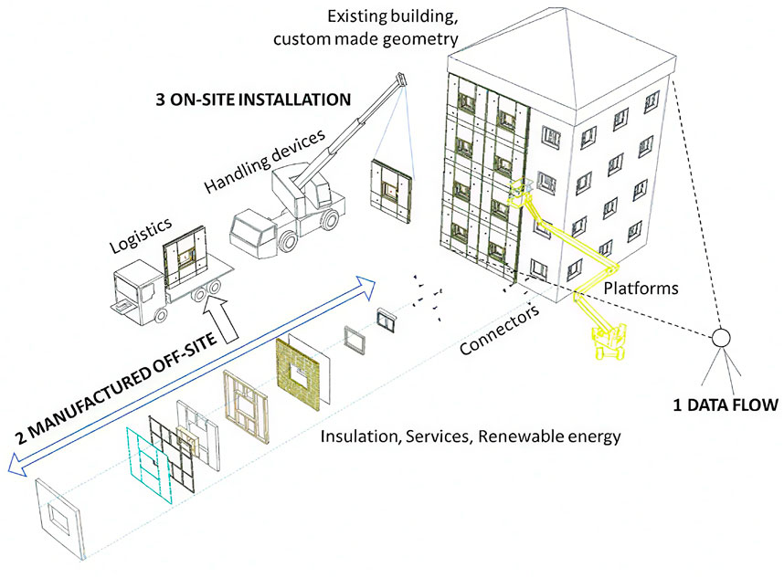
Figure 1. Building renovation with prefabricated modules.
Although prefabricated components have been introduced for residential renovation, they have yet to achieve broad market penetration, primarily because they are not as cost-effective as conventional manual techniques. The ENSNARE research initiative seeks to cut down the time required for data collection and processing by 90%, in addition to shortening both the manufacturing and assembly phases. However, these time savings must not compromise quality or violate relevant codes and regulations. Mistakes in the data pipeline can cause discrepancies in the prefabricated elements, which may lead to leakage of water or heat, physical clashes, or difficulties during installation on-site.
The viability of using robotics and automated technologies for renovating residential buildings is closely tied to their cost-effectiveness (Skibniewski and Hendrickson, 1988; Balaguer and Abderrahim, 2008; Warszawski, 1985; Hu et al., 2020). In addition, effectively managing and preparing these technologies for commercialization is a critical concern (Pan et al., 2020a; Pan et al., 2018; Pan et al., 2020b). This topic has been explored in earlier research efforts, such as the BERTIM and HEPHAESTUS projects. Prior investigations have also identified as many as 15 specific RG (research gaps) in this domain.
In the domain of residential building renovation, the adoption of pre-fabricated modules for energy efficiency and renewable energy generation often faces limitations in competitiveness compared to manual methods, primarily due to the need for more extensive and precise project planning. When considering the use of such modules, stakeholders—including property owners, developers, and engineers—must gain a thorough understanding of the building’s potential for solar energy production, associated investment costs, and insulation requirements early in the planning phase. This process necessitates the creation of a georeferenced 3D (three-dimensional) model of the building, capable of accurately reflecting its geometry, structure, and suitability for integrating prefabricated components and photovoltaic systems. Within this framework, the configuration of solar panels and prefabricated wall elements becomes particularly important, as it enables an assessment of how many solar panels can be installed on the façade, the amount of insulation required, and the projected financial outlay.
Each component of the proposed workflow has been designed to overcome specific market limitations and research gaps. The online data acquisition step eliminates the necessity for costly and error-prone on-site surveys. The utilisation of structured BIM modelling has been demonstrated to address the fragmentation of planning, thereby enhancing the early-stage integration of solar energy generation and envelope insulation objectives. AprilTags facilitate millimetre measurement, and thereby establish that the CAM pipeline facilitates the generation of modules that are both consistent and free of errors. Finally, the robotic assembly step solves the current barrier of labour-intensive, inflexible on-site installation by automating pick-and-place with vision-based guidance. To clarify the workflow required in this study, the following steps have been identified as essential.
• Robot systems have not been practically adopted for the automated assembly of pre-fabricated construction elements.
• Limitations of conventional systems:
• Dependence on measurements of the building’s geometry is necessarily made on the site, with the subsequent need to travel there even in the previous stages when the contracts with the building owner or client are not defined yet.
• Manual definition of the Renovation project with prefabricated modules
• lack of a fluid link between the BIM and the CAM of the Robotic Assembly.
• In the Robotic Assembly, typically restricted to handling identically sized components with repetitive operations
• Our proposed solution: From Online Data to Robotic Assembly
• Online Data Acquisition: Utilizes publicly available inputs to generate an initial digital model without requiring on-site surveying.
• Existing Building Modeling BIM: Establishes a simplified yet structured 3D model to capture geometry, layout, and key façade elements.
• Building Renovation Project BIM: Integrates design objectives and layout configurations into the digital model for prefabrication planning.
• AprilTags: Enable precise localization and adjustment by linking physical reference points with digital models.
• Assembly CAM: Translates refined geometry and connector placement into machine-readable fabrication instructions.
• Robotic Assembly: Execute physical construction via a robotic arm with vision-assisted pick-and-place and an extended linear axis for workspace adaptability.
This study aims to establish an automated renovation workflow that addresses the limitations of conventional systems—namely their reliance on repetitive geometry, constrained robotic reach, and manual site measurements. By introducing an integrative workflow that starts with online data acquisition and evolves through BIM-based modeling, building renovation project, automated CAM generation, and precise and flexible robotic assembly of pre-fabricated façade modules. The core objective is to demonstrate how a semi-automated, data-driven approach can significantly improve the efficiency, accuracy, and scalability of building renovation processes.
2 Related work
2.1 Data acquisition and accurate measurement with AprilTags
Automation in renovation projects begins with accurate data acquisition and digital modeling. Numerous studies have emphasized the importance of digitizing existing buildings to support downstream processes such as manufacturing and robotic assembly. Lasarte et al. (2017) and Ali et al. (2021) proposed BIM-based tools for automated design and planning, enabling stakeholders to define layout configurations and geometries in early stages. Digital planning tools that integrate public data and facade geometry have been used to semi-automate layout creation and visualization for prefabricated facade modules Iturralde et al. (2023a) and Iturralde et al. (2023b).
Computer vision and photogrammetry are widely applied to enhance geometric fidelity during data capture. ArUco and AprilTags are among the most used fiducial markers for localizing building elements in unstructured environments Iturralde et al. (2019) and Zhang et al. (2021). Feng et al. (2014) and Tish et al. (2020) implemented monocular or RGB-D vision systems to localize façade components and improve assembly precision. UAV-based systems for facade inspection and marker placement are gaining popularity for their efficiency in reaching tall structures (Hsu et al., 2024).
Despite these advancements, many approaches remain fragmented and manually intensive. Most systems do not incorporate a feedback loop that updates the building model based on accurate on-site measurements. Additionally, integration between web-based data collection and real-time layout reconfiguration is limited.
2.2 CAM
CAM platforms are critical in translating 3D models and layout definitions into manufacturable components. Studies such as Sandberg et al. (2016) and Iturralde et al. (2024) explored the use of Revit, Dynamo, and Dietrich’s® software to automatically generate timber frame components, connector locations, and insulation layers for prefab facades. Lasarte et al. (2017) and Iturralde et al. (2022) proposed data workflows linking geometric modeling to the generation of manufacturing-ready instructions, incorporating data structures compatible with CNC (Computer Numerical Control) fabrication.
To enable mass customization while maintaining manufacturability, layout algorithms must account for production constraints such as minimum/maximum module sizes, alignment tolerances, and connector types. Augustynowicz et al. (2021) implemented parametric design frameworks for multi-robot fabrication of wood facades, while Pan et al. (2018) and Pan et al. (2020a) highlighted the importance of early integration of manufacturing logic into renovation planning.
Still, one of the key limitations in the literature is the lack of synchronization between modeled layouts and actual site conditions. Errors in the data acquisition stage often propagate through CAM, leading to misalignment during assembly. Furthermore, few workflows automate error correction once physical fabrication begins.
2.3 Robotic assembly
The use of robotics in the on-site assembly of prefabricated modules has been a growing field of investigation. Hook (2016) and Kasperzyk et al. (2017) presented early concepts of robotic arms for facade fabrication and reconstruction. Iturralde et al. (2021) and Iturralde et al. (2022) explored different robotic strategies for assembling prefabricated wall systems, including rail-mounted manipulators for extended reach. Vision-based closed-loop systems have also been proposed to guide pick-and-place tasks (Feng et al., 2014; Tish et al., 2020; Ali et al., 2021).
Robotic platforms that integrate with digital models via ROS and CAD workflows have demonstrated promising results in handling diverse component geometries and layout configurations (Iturralde et al., 2023c). Marker-based localization systems (Romero-Ramirez et al., 2018; Garrido-Jurado et al., 2016) combined with motion planners like Chitta et al. (2012) have been used to ensure flexible, adaptive operation in semi-structured environments.
However, most systems remain confined to laboratory-scale prototypes or simulation environments. Key challenges that remain unresolved include adaptability to non-flat surfaces, regulatory constraints for on-site deployment, and safety compliance for operation in real building conditions. Furthermore, multi-storey scalability and marker-less operation have yet to be fully addressed.
While significant progress has been made in each domain offer a fully integrated pipeline that spans from online data capture to on-site robotic execution. This paper addresses these limitations by developing and validating an end-to-end workflow that integrates online modeling, automated CAM generation, and flexible robotic assembly for prefabricated facade modules.
3 Integrated workflow
The integrated workflow depicted in Figure 2 showcases an integrated workflow for data-driven building renovation, encompassing processes from initial data acquisition to robotic assembly. The process commences with the acquisition of data online, which furnishes contemporary information regarding the prevailing structure. This data informs the generation of an Existing Building Modeling BIM, serving as a foundational digital representation. Consequently, a Building Renovation Project BIM is derived, integrating renovation objectives and design adjustments. The implementation of an accurate measurement and adjustment BIM loop is instrumental in ensuring precision, a process that involves the feedback of refined data to both the existing and project BIM models. AprilTags are utilized to facilitate spatial localization and tracking during on-site operations, thereby enabling the alignment of digital plans with physical environments. Subsequently, the information is relayed to the Assembly CAM stage, where computer-aided manufacturing instructions are generated based on the BIM data. Robotic Assembly is responsible for executing the renovation tasks, leveraging CAM outputs and real-time spatial data to facilitate automated construction activities with a high degree of precision.
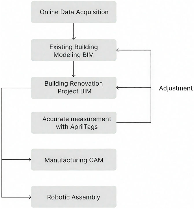
Figure 2. Integrative Workflow overview.
3.1 Online data acquisition platform and building modeling
The necessity to address the growing demands of climate action has resulted in the construction industry, particularly in the field of building renovation, becoming a leading centre for environmental innovation. However, traditional renovation approaches frequently exhibit deficiencies in terms of fragmented workflows and excessive reliance on manual processes, which impede scalability and widespread adoption. Digital tools that are efficient, accurate, and user-friendly are essential to overcome these limitations and support large-scale energy retrofitting. In this context, online building modelling emerges as a crucial solution by significantly reducing the need for on-site visits and manual measurements, streamlining the early stages of renovation, and accelerating the overall process.
3.1.1 Method
In response, this study introduces a structured online platform tailored to streamline the data acquisition and modeling processes vital for building renovation. This platform provides a systematic approach, guiding users through a series of steps that begin with the collection of fundamental geometric data and culminate in the creation of a normalized 3D model compatible with BIM formats, such as. ifc shown below. By automating critical steps and ensuring data integrity, the platform addresses the fundamental limitations of current practices while promoting accessibility for non-expert users.
Enter project name: test01
Enter building name: building01
Enter building height in meters: 12
Enter number of floors: 4
Floor height is: 3.0 m
Enter changed height of each floor: 3
Building height is: 12.0 m
Enter extrusion length in meters: 0.3
The data acquisition platform uses a modular pipeline to generate a normalised 3D representation of building façades, incorporating both user inputs and image-based detection. As shown in Figure 1, the process begins with the collection of two types of information from the user: (1) façade images and (2) basic building metadata, such as the number of floors, total height, and extrusion depth. These are submitted to the platform, where the geometric data is processed alongside a vision-based module that uses pretrained algorithms to extract façade opening features (e.g., windows and balconies). This step produces a. json file containing spatial data on the openings in the façade.
As illustrated in Figure 3, the user-submitted metadata is used separately to generate an initial model structure represented as a. json file without opening information (Process 2). The detected openings are pre-processed and refined (Process 3), after which the two data streams are combined into a unified JSON file containing complete geometric and topological data (Process 4). The platform then generates a. json file with integrated opening information (Process 5) and performs normalisation (Process 6) to produce a final file that complies with BIM standards. This normalised file is structured for compatibility with downstream tools, including FreeCAD, IFC exporters, and CAM modules. The modular nature of this pipeline ensures flexibility, allowing updates to individual steps without disrupting the entire workflow. The result is a high-fidelity digital representation of the building that supports accurate energy modeling and renovation planning. This stepwise approach has been shown to reduce manual intervention and to promote consistency and reproducibility across projects, a critical advantage in large-scale renovation efforts (Ferrandiz et al., 2018; Mainicheva et al., 2017; Chegu Badrinath et al., 2016).
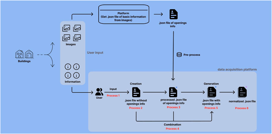
Figure 3. The flowchart of the data acquisition platform.
The platform addresses the issue of incomplete user input—especially for building heights—by integrating a height estimation feature grounded in projective geometry. This algorithm utilizes camera parameters and image-based measurements to compute real-world building heights, even in cases where data is sparse. The user is only required to provide the horizontal distance, D. The remaining values, such as sensor size and resolution, are automatically extracted, thereby significantly reducing the barriers to accurate modeling (Gerum et al., 2019).
3.1.2 Experimental validation
The platform’s viability was substantiated through a series of pilot studies on buildings of varying complexity. In the case in Figure 4, a building with six facades was processed to verify the platform’s fundamental functionality.
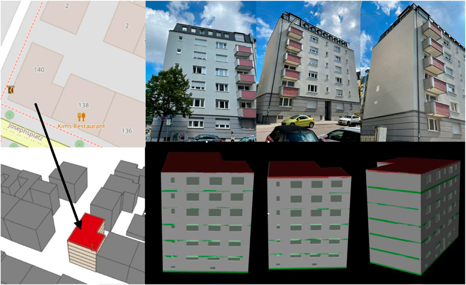
Figure 4. Example of the simple building.
To be mentioned, the input of this platform should be from users, and the output should be the final normalized. json file, which can be transferred into the. ifc file for the visualization. And the approximate external shape of the model and the address information (Munich, Germany) are provided here on the left side of Figure 4.
3.2 Semi-automated building renovation project
In the context of building renovation, the integration of prefabricated façade modules is a critical step in bridging the gap between digital design and physical implementation. This section addresses key challenges by proposing a data-driven approach that links early-stage building modeling and measurement with downstream manufacturing and on-site assembly. A major barrier to the adoption of prefabricated modules, especially those incorporating renewable energy systems, lies in the need for manual layout drafting and iterative adjustments by designers throughout the renovation process—a task that is both time-intensive and difficult to scale. To overcome this, the proposed system introduces two innovations: first, an automated generation of optimized façade layouts and solar panel distribution based on existing building models; and second, a dynamic adjustment mechanism that adapts the layout in real time according to the renovation phase and the evolving precision of measurement data.
3.2.1 Method
The renovation process begins with the generation of a 3D model of the building using publicly available facade images and OpenStreetMap (OSM) floor plans. From these inputs, a structured geometric model is created as shown in Figure 5a, which serves as the foundation for the placement of the modules. The FreeCAD-based plugin was developed to generate layout configurations of prefabricated facade elements integrated with photovoltaic and thermal solar panels. This tool allows users to analyze wall geometries, extract facade features (e.g., height, width, corner points, and window locations), and simulate solar panel arrangement strategies, streamlined early-stage planning that is typically time and labor-intensive.
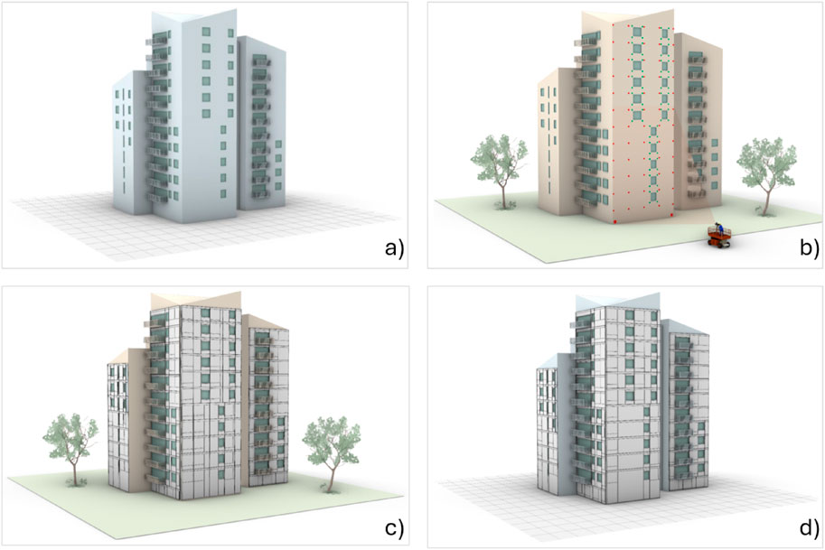
Figure 5. (a) Building model generated with building images and OSM, in this case, the demo-building in Milan. (b) Capturing the real building images with AprilTags, which are located at the critical points of the facade. Example of the demo building in Milan. (c) Building model and detailed prefabricated module layout of the demo-building in Milan. (d) Output of the code described in this section RG1.2, that includes a prefabricated layout definition, including solar panels and registration areas in the building model of the demo-building in Milan, Italy.
The core goal is to automate the placement of prefabricated modules on the building facade based on geometric feasibility and energy efficiency. A multi-step logic is applied to optimize the number of solar panels while respecting architectural constraints, such as window positions and panel dimensions. The layout generation process shown in Figure 6 is completed in minutes and provides detailed visualizations, facilitating informed decisions by architects and engineers. The modules include structural frames, insulation layers, and wiring pathways, making them ready for robotic assembly.
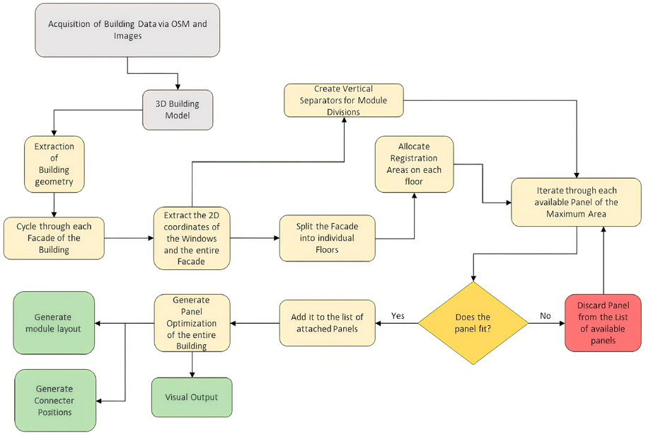
Figure 6. Flow-chart of the solution RG1.2. The inputs are shown in gray, the outputs in green, and the steps required in yellow.
3.2.2 Experimental validation
Once the initial layout is approved, precise on-site measurements are captured using AprilTags positioned on key facade points like window edges and connection anchors as shown in Figure 5b. These measurements are used to update the digital model with higher accuracy. The system then automatically reconfigures the prefabricated module layout to align with the measured geometry, minimizing errors during production and installation, as shown in Figure 5c. This adjustment process addresses the limitations of initial online modeling and enhances the reliability of the final output.
All outputs—including updated FreeCAD models, JSON files with module data, and Excel reports listing connector positions—are structured to support direct integration with robotic fabrication workflows. These outputs also include dimensional data critical for CAM, enabling precise prefabrication of the components.
An example application on a complex 3,000 m2 facade (the Milan demo building) demonstrated that what once required over 1,000 h of manual drafting can now be accomplished in under an hour with this system (25 min each for layout definition and realignment). Figure 5d illustrates the updated building model after layout optimization.
This implementation showcases how a data-driven and semi-automated workflow—starting from online modeling and ending in precise on-site layout adjustment—can transform renovation into a scalable, industrialized process, significantly lowering cost and time while preserving architectural integrity and energy performance.
3.3 Facade geometry accurate measurement
While the building renovation project is done, the AprilTag-based technique enables high-precision enhancement of facade geometry, ensuring greater modeling fidelity before the CAM phase.
3.3.1 Method
First to be mentioned, the development of a quadcopter with an end effector was undertaken based on Hsu et al. (2024). The following text is an excerpt from the aforementioned source: The quadcopter will approach the target position. The application of the load to the end effector is indicated by the presence of the AprilTags. The reverse side of the tags bears the following inscription: The adhesive is applied in the following manner. Following the establishment of contact between the tags, the surface on which the pressure is to be applied by the quadcopter is hereby designated as the “target surface”. It is imperative that the tags are utilized in order to guarantee a robust binding. The process is indicated as illustrated in Figure 7.
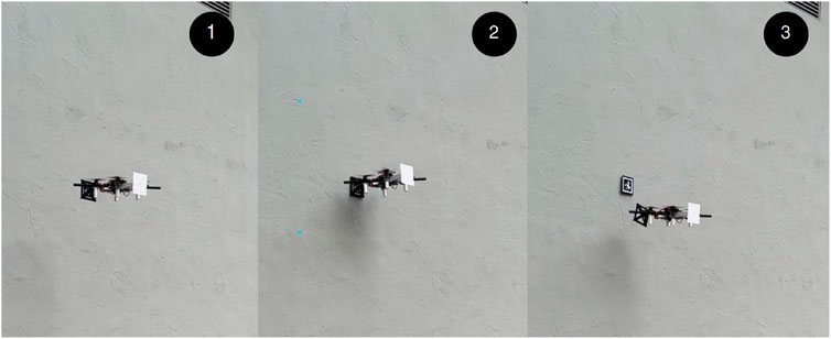
Figure 7. Sticking process.
Traditional survey methods, while often precise, tend to be labor-intensive and constrained by logistical and financial limitations. To address these challenges, fiducial markers known as AprilTags have been employed to enable efficient 3D reconstruction of building facades using only digital imaging and straightforward computational techniques (Zhang et al., 2021). These markers, when arranged in systematic grid formations on the surface of a structure, facilitate the derivation of spatial geometry through triangulation methods based on calibrated camera imagery.
A key innovation in the proposed integrative workflow is the use of a best-fitting plane to reduce spatial noise and improve the alignment of coplanar data points derived from AprilTag positions. By applying a least-squares optimization, the reconstructed points are projected onto the most likely planar surface, significantly enhancing the accuracy of the model even in the presence of minor measurement errors or optical distortions (Iturralde et al., 2023b). This correction method is particularly valuable when the resulting geometric model is used for applications with stringent spatial requirements, such as determining optimal solar panel placement or simulating urban light exposure.
Central to the integrative workflow’s accuracy is a robust approach to distance estimation. This is achieved through the use of effective focal length and sensor pixel size, which together allow for precise real-world measurements based on the apparent size of the tags in the image frame. The system leverages camera calibration data and computes distances using a similarity-based geometric model, ensuring that the spatial positions of each tag can be accurately resolved. The experimental setup employed a high-resolution Sony Alpha 7R IV camera, with a computed effective focal length of approximately 13,257.6 in appropriate units, delivering sub-millimeter accuracy in tag distance estimation.
3.3.2 Experimental validation
In practical testing, a key factor affecting accuracy is the apparent size of the AprilTags within each image. For instance, when capturing a 15-meter-high building, the 200 mm
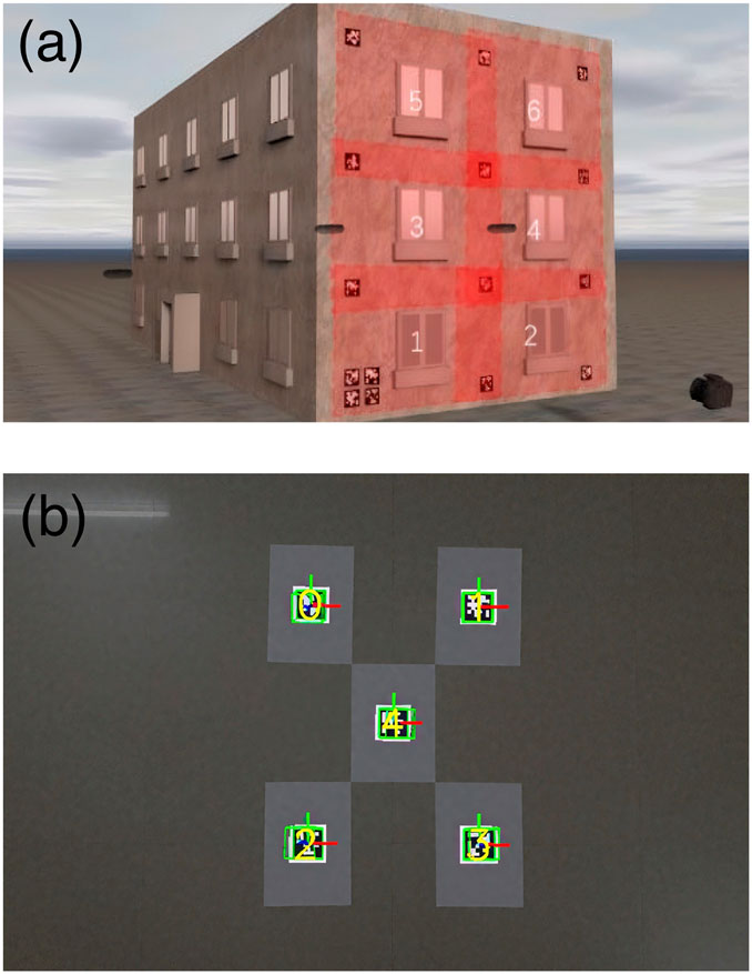
Figure 8. (a) Shooting local targets. (b) Detection results.
Once the distances to the individual tags are known, the system proceeds to determine their 3D coordinates relative to the camera. This is followed by projecting those coordinates onto the best-fitting plane, refining their placement before final distance measurements are made using Euclidean metrics. The AprilTag detection, as shown in Figure 8b, and data processing were implemented using Python libraries such as the AprilTag detector and scikit-spatial for plane fitting, enabling a streamlined and accessible reconstruction integrative workflow with minimal manual intervention.
Additionally, for cooperating with AprilTags, the MK (Matching Kit), which is a set of components that includes a bespoke interface for the purpose of correcting any deviations that occurred during the placement of the AprilTags on the wall, is introduced here with regard to Iturralde et al. (2023c). This MK is not predicated on a specific connector type; rather, it is founded upon a conceptual framework that delineates the interface between the facade and the wall. In previous phases of the research, the MK and its main components were defined. A series of tests was conducted, resulting in enhanced accuracy and reduced time consumption. The MK is comprised of three primary components (see Figure 9).
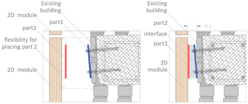
Figure 9. Left: Flexibility of the MK. Right: The shape of the interfaces.
3.4 Assembly CAM
The results from the AprilTags phase, especially the clear definition of module shapes and connector positions, provide a strong digital base for the next manufacturing steps. The system can turn these layouts and measurements into machine-readable files. This smooth connection with CAM tools allows for the accurate production of facade parts like solar panels and frames, with little manual work. Moving from digital planning to automated making is a key step toward a fully connected and scalable renovation process.
3.4.1 Method
An integral step in streamlining facade renovation using prefabricated modules is the seamless integration of automated layout generation with CAM systems. In the workflow, once the primary layout of prefabricated facade modules is derived from a 3D Point Cloud, this geometric information is directly linked to CAD/BIM environments and ultimately synchronized with CAM platforms to enable digital fabrication of the modules (Sandberg et al., 2016). This process effectively minimizes manual intervention and ensures that the layout generated from existing building geometries can be translated into manufacturable components with minimal redesign.
The CAM integration is facilitated through interoperability with software such as Revit via Dynamo™ scripts, which convert the semi-automatically extracted polygonal module boundaries into CAD-readable formats (Sandberg et al., 2016). These formats can then be used to define the structure and configuration of prefabricated panels in manufacturing software like Dietrich’s®, which automates the detailing of structural components such as studs, insulation layers, and fireproof barriers once the primary layout is defined (Sandberg et al., 2016; Iturralde et al., 2024). This bridge from data acquisition to fabrication not only enhances design efficiency but also enables mass customization of building envelopes while preserving the geometric fidelity of existing structures.
A crucial advantage of this approach lies in its adaptability to production constraints. The semi-automated layout algorithm takes into account key CAM parameters, such as maximum and minimum module widths, slab positions for connector placement, and alignment with existing window openings (Sandberg et al., 2016). These design rules are incorporated upstream in the layout generation process to ensure that the final output adheres to manufacturing limitations, thus avoiding costly revisions downstream.
However, the success of the CAM integration is strongly dependent on the quality of the initial Point Cloud. As highlighted in the study, inaccurate or incomplete point data can propagate through the entire integrative workflow, resulting in deviations between the generated layout and actual building conditions—especially problematic when modules must fit tightly to existing facades with minimal tolerance (Sandberg et al., 2016).
3.4.2 Experiment validation
Based on the rationale above, a CAM generation workbench named ENSNARE_CAD_CAM is created in FreeCAD, allowing geometry properties of individual profiles across an entire module to be exported as a single JSON file. The geometry properties that can be exported include each profile’s dimensions, CoM (Center of Mass), and placement relative to the origin of the module as shown in Figure 10a.

Figure 10. (a) Flowchart of the geometry analyzing procedure using FreeCAD. (b) Flowchart showing current CAM procedure.
A Python script is implemented to extract the coordinates of each PUP (Pick-Up Point) and derive the optimal sequence based on the JSON file. A ROS wrapper is then implemented to expose this two information as a ROS service, enabling the main controller to request the data at run time. By requesting the assembly sequence, a list of strings containing the names of the modules is returned. Sequentially, quarrying with the name of each module, the PUP coordinates are returned.
With the automated prefabricated facade layout definition process developed in Iturralde et al. (2023b), the properties are automatically extracted from the CAD model and exported to a Excel file, from which a Python dictionary is implemented to index these data in an easy-to-retrieve manner. The same as before, a ROS wrapper exposes the relevant data as ROS services. This new procedure increases data retrieval efficiency, as shown in Figure 10b.
3.5 Robotic assembly
The subsequent phase of the pipeline focuses on translating the detailed fabrication outputs generated in the CAM workflow into precise physical operations through robotic assembly. The CAM-generated layout encapsulates the geometric and structural parameters of each prefabricated component, as well as embedding essential metadata, such as PUP and assembly sequences, required for automation. These outputs serve as direct input for the robotic system, thereby facilitating a seamless transition from design to execution. The robotic platform is programmed to autonomously interpret, locate, and assemble modules with minimal human intervention by leveraging structured data exported via FreeCAD and indexed through ROS services. This integration serves to illustrate the continuity of the end-to-end workflow, wherein the fidelity of digital planning is preserved and actualized through intelligent robotic manipulation.
3.5.1 Method
Before updating the layout to match real site conditions, it’s important to make sure the initial design fits the building as it actually is. Since older buildings often have small differences or irregular shapes, this step helps prepare the layout for accurate adjustment. The next part explains how the layout is first created using the building model and design rules.
The architecture implements a data-driven pipeline that systematically processes geometric information from CAD models into executable robot trajectories. The pipeline begins with the Geometry Analyzer, which parses the CAD model to extract critical parameters including component dimensions, PUPs, and optimal assembly sequences based on spatial constraints. These parameters are encoded as transformation matrices and sequential instructions that flow to the Motion Generator. This module performs coordinate frame transformations between the module origin frame MO and the robot’s world frame w using homogeneous transformations, converting design specifications into robot-specific target poses. The resulting pick-and-place coordinates are then processed by the Robotic System Control modules, which decompose the assembly task into synchronized trajectories for the manipulator, linear rail, and gripper subsystems. This modular architecture enables real-time adaptation to component variations while maintaining assembly precision through feedback between the digital model and physical execution.
3.5.1.1 Hardware design
The designed prototype of the robotic system for assembling prefabricated modules is depicted in Figure 11a. This system primarily comprises a UR10e industrial robot manipulator (Universal Robots, 2023) integrated with a linear rail unit. The manipulator’s base is mounted on the rail, extending the robotic arm’s reach and creating a 3.0 m
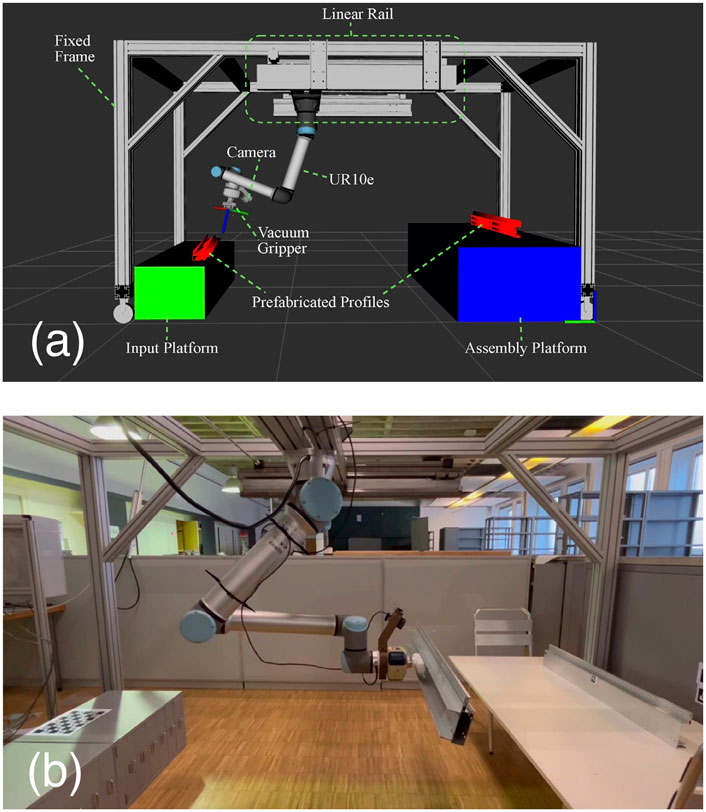
Figure 11. (a) Hardware design overview. (b) The real system in assembly process.
3.5.1.2 Software design
The primary function of the software is to determine the optimal positions and orientations for the gripper to effectively pick and place prefabricated profiles of varying sizes and command the robot to move accordingly to finish the assembly process while avoiding collision with the system boundaries and other components along the way. To achieve this, a geometry analyzer is employed to extract the geometry properties of the prefabricated modules from their CAD model and calculate an optimal assembly sequence as well as the coordinate of a PUP for each component, i.e., where the gripper should grasp the component. Based on this information, a motion generator calculates the PUP coordinates relative to the robot frame as the target poses for the robotic gripper. The target poses are then sent to each part of the hardware system in a sequence to execute the trajectory and complete the assembly process. A flowchart of the whole program is illustrated in Figure 12a.
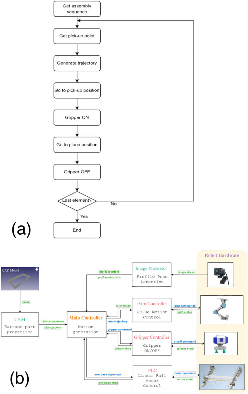
Figure 12. (a) Flow chart of the main controller. (b) Software architecture and data flow.
The software is designed modularly and is developed within the ROS (Robot Operating System) framework for easy interfacing with the robot hardware and seamless communication between modules. Figure 12b depicts the software architecture and the data flow between different modules. The design of each module is explained in detail in the following section. Section 3.5.2.1 introduces how to extract the geometry properties of the profiles from the CAD model. Section 3.5.2.2 explains how the coordinates are transformed into the robot frame to calculate pick-and-place poses. The robot hardware controller (Section 3.5.2.3) consists of three parts, each controlling one hardware component of the system, i.e., the UR10e manipulator, linear rail motor, and the gripper. An optional camera with a marker-based visual localization program, explained in Section 3.5.3, aids a more flexible placement of the profiles as well as the input and assembly platforms, and enhances the accuracy.
3.5.2 Software modules
Once the layout has been corrected based on real measurements, it needs to be turned into files that machines and robots can use. This step is important to make sure each part is made and placed correctly. The next part shows what kind of output files are created and how they are used in the production process.
3.5.2.1 Geometry analyzer
Two key pieces of information are required to be extracted from the CAD model to automate the assembly process of prefabricated profiles of various sizes. The first is the PUP, i.e., where the end-effector attaches when picking up. This is usually chosen at each profile’s CoM to ensure stability during transportation by the robot arm. In our study, however, because the vacuum gripper can only attach objects from their surfaces, the PUP is selected as the CoM shifted by a certain height to the upper surface. In case the upper surface is irregular and the gripper cannot firmly attach the CoM point, the PUP is chosen by the geometry center of the largest plane. The second information required is the assembly sequence, i.e., in which order the profiles are picked and placed. Once all the PUPs are determined, an optimal sequence is derived through the nearest-neighbor algorithm that chooses the closest PUP as the next pick-up point.
3.5.2.2 Motion generator
With the PUP coordinates, the appropriate motion of the robot is generated to pick and place the profiles.
Based on Equation 1, the PUP coordinates obtained from the geometry analyser are relative to the module origin frame {MO} and can be represented by the homogeneous transformation
where
For picking up, the PUPs are aligned in the same pre-defined pose on the input platform, so the robot picks up all the parts from the same place. However, the placements differ for different parts based on the PUP coordinates. Seeing from Equation 2, the user can pre-define a target pose for placing the whole module, i.e., the pose of the frame {MO} relative to the world frame of the robot’s workspace {w}, denoted by
In this way, the end-effector pose for picking up and placing down each component is calculated. The pick and place pose is sent to the robotic hardware controller to move the robot to the target position to complete the assembly sequence.
3.5.2.3 Robotic System Control
With the pick-and-place poses for the end-effector, trajectories of both the rail base and the robot arm are generated by utilizing the motion planning tool (MoveIt, 2023a). The entire robotic assembly unit, including the manipulator and linear axis system, is configured using MoveIt’s setup assistant tool and visualized in RViz, the visualization tool of ROS, providing a simulation environment for offline testing. Since the whole system is perfectly modeled, there is no sim-to-real gap. Once the trajectories are validated in the simulation, they can be exactly repeated in the real system. The fixed structure of the assembly system, input and assembly platforms, as well as the facade components to be assembled, are all modeled as collision objects in MoveIt, allowing MoveIt to consider the geometry constraints and plan a collision-free trajectory.
The control of the robot system is divided into three parts, which are introduced in the following subsections.
3.5.2.4 Robotic arm motion control
To control the motion of the robotic arm, the official Universal Robot ROS Driver is utilized in conjunction with the trajectory planner MoveIt. With the Cartesian waypoints of the end-effector derived in the previous section, MoveIt calculates optimal, collision-free joint trajectories and inverse kinematics. The ROS driver writes the joint trajectory commands to the robot hardware while reading the actual joint states in real-time and feeding them back to the planner.
3.5.2.5 Gripper control
The electric pump of the vacuum gripper is connected to the manipulator UR10e through the robot’s tool I/O. The UR ROS Driver also provides a ROS service interface to access all the robot’s digital I/Os, including the tool I/O. With this service, we can easily turn on/off the vacuum suction force by calling the ROS service set_io to set/reset the tool output.
3.5.2.6 Linear rail motion control
The motion of the linear rail motor is controlled by a Beckhoff PLC (Programmable Logic Controller). The controller is programmed with the motion controller module in the TwinCAT 3 software platform. The integration involves careful motor behavior parameterization and calibration to ensure optimal performance and precision.
Additionally, two limit switches are installed at both ends of the rail, marking the maximum range of rail motion. When the robot reaches the end of the rail and triggers the sensor, a signal is fed back to the controller to stop the motor, enhancing the safety of the robotic system.
State Machine A state machine, as illustrated in Figure 13, is implemented in the PLC main program to manage motor control. Each state corresponds to a specific function block that dictates a particular motor behavior. Upon starting the PLC, the linear axis system is powered on, after which the main program can trigger other states via ROS commands. These include “Homing,” “Motion States,” and “Stop”. The “Motion States” category encompasses the various movement options available from the PLC motion library, such as “MoveAbsolute”, “MoveRelative”, and “MoveVelocity”.
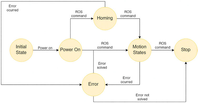
Figure 13. State machine of the PLC motor controller.
In the event of an error during motion, the state machine transitions to the Error state, where the error handler attempts to resolve the issue. If the error is successfully resolved, the system can resume motion upon receiving a new ROS command; otherwise, it will remain in the Stop state.
PLC-ROS integration to seamlessly integrate the PLC-controlled linear axis with the main ROS program, a communication interface is established using Beckhoff’s ADS (Automation Device Specification) protocol. This TCP (Transmission Control Protocol)/IP (Internet Protocol) -based protocol enables real-time data exchange between the Beckhoff PLC and ROS on the main control PC in Linux, allowing synchronized control and feedback for both the linear axis and robotic arm.
The communication interface, implemented using Beckhoff’s ADS C++ library (Beckhoff Automation, 2023), allows the main controller to interact with the PLC by specifying the PLC’s IP address and AMS (Automation Message Specification) Net ID. This enables the reading and writing of key PLC variables, such as motor position and velocity, enabling the main controller in ROS to send commands or read states efficiently. However, the communication channel is blocked during data transmission in one direction. To enable simultaneous reading and writing, the ADS Notifications protocol is employed to cyclically transmit motor state data to the main controller in a background thread without interrupting motion execution.
3.5.3 Accuracy improvement with visual marker detection
The successful execution of the assembly task relies on high precision in the installation and calibration of the robotic assembly system. Any offsets between the simulated and real model, for instance, the displacement of the manipulator’s base on the rail or imprecise calibration of the location of input and assembly platforms, lead to deviation of the final assembly result. To eliminate potential errors and avoid cumbersome calibration, a camera is mounted on the wrist of the robot arm to detect the position of the platforms and the profiles at run-time. Advanced ArUco markers (Kedilioglu et al., 2021) are attached to the platforms and the PUP on the profiles. A marker-based vision approach is utilized to accurately detect and calculate the pose relation between the end-effector and the profiles.
As shown in Equation 3, a hand-eye calibration that determines the transformation between the camera optical frame and the end-effector frame
The target pose in the world frame is, therefore:
By applying the Equation 4, any marker pose in the world frame can be easily obtained if the camera detects it. If the marker is attached to the PUP of each profile, the picking poses for the end-effector can be calculated at run-time instead of using the manually assigned coordinates measured in advance, which can be inaccurate. Moreover, instead of feeding the profiles to the input platform at the same position every time, now the profiles can be casually placed at any point on the input platform where the camera can detect them. Similarly, by attaching a marker on the assembly platform where the module origin should be, we can save the effort of manual coordinate measurements.
3.5.4 Experimental validation (robotics part)
Two sets of experiments are conducted to validate the accuracy and efficacy of the presented system. The first one evaluates and compares the accuracy of the pick-and-place poses of a single aluminum part with and without the visual marker detection module, as shown in Figure 14(1). The second experiment evaluates the success rate of the full assembly process of a prefabricated module consisting of four aluminum parts and demonstrates the efficacy of the presented system in real applications.
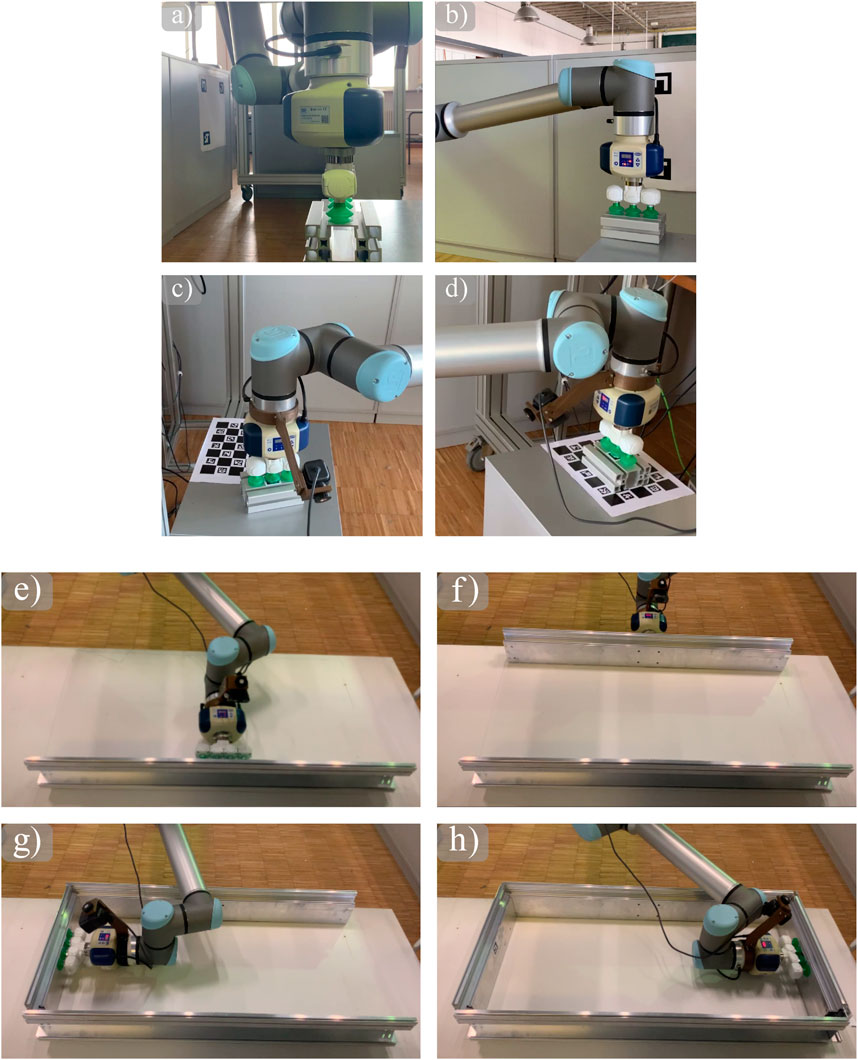
Figure 14. (1) Pick-and-Place of a single aluminum part in baseline mode (a,b) and visual-aid mode (c,d). (2) Snapshots of the placing of profiles (e-h).
We first evaluated the accuracy of picking and placing a single aluminum part using the presented system, with and without the visual aid module. In both experiments, as shown in the snapshots in Figure 14(1), an aluminum part is picked up from the input platform on the left side and placed on the assembly platform on the right side. The difference is, in the baseline mode without the visual aid, the pick and place positions are pre-defined in the calibrated workspace, whereas in the visual aid mode, the pick position is marked by the ArUco marker attached on the surface of the aluminum part, and the place position is marked by the ArUco marker attached to the assembly platform, such that the part can be pre-placed at any position on the input platform. We conducted 10 experiments in each mode and measured the average errors of position and orientation, separately. The position error is based on 2D (two-dimensional) Euclidean distance between the actual positions to the reference positions, and for orientation, we measure the yaw angle error wrapped between
Table 1 shows average errors in the position and orientation of the pick and place in each mode, respectively. Discussion: Without visual aid, small errors for picking and large errors for placing the side. The reason is that calibration is done at the robot’s home position, which is closer to the pick positions. Errors occur when the rail moves since the rail system is not calibrated, so the other side has large errors. With visual aid, the errors mainly come from changes in light conditions and the noise of marker detection. The increase in orientation error observed in the tag-based (visual aid) mode is primarily due to variability in lighting conditions and detection jitter in the ArUco marker pose estimation. While visual localization improves flexibility and position accuracy, small angular deviations may result from inconsistent tag visibility or blur in the image frame. This is more pronounced during placement tasks that require finer rotational alignment, especially when the robot arm is operating far from its calibrated home position.
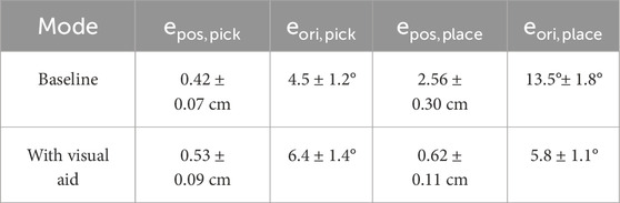
Table 1. Average errors in position and orientations of picking and placing a single aluminum part with and without visual aid over 10 experiments each.
Furthermore, we compared task durations between traditional manual approaches and the automated system. As shown in Table 2, tasks such as facade layout and clash-checking were reduced from hundreds of hours to under an hour, demonstrating the pipeline’s substantial time-saving potential.
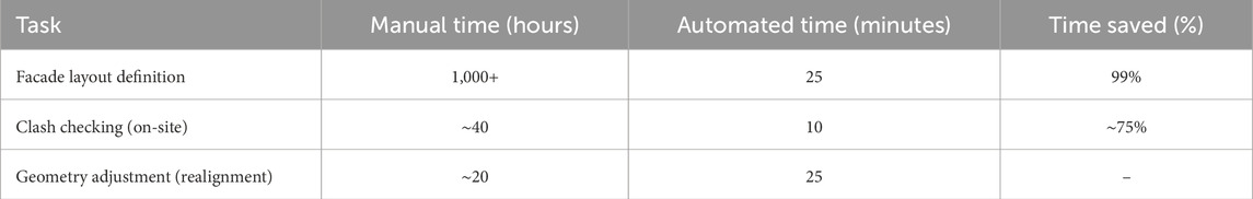
Table 2. Comparison of manual and automated execution time for key renovation tasks.
3.5.4.1 Efficacy assessment
The second experiment assesses the whole process of assembling a prefabricated module in the visual-aid mode. The square-shaped module to be assembled consists of 4 prefabricated aluminum profiles that interlock with each other. The upper surfaces of the profiles are not flat and cannot be picked up by the vacuum gripper. Therefore, we select the PUP at the geometry center of the inner side surface of each profile. This selection and the fact that the profiles are interlocked add more geometry constraints to the planner. To ensure the success of assembly, a few trial test is conducted offline in simulation to find the optimal waypoints for the end-effector. Although this process requires manual effort from the user, once an optimal set of waypoints is determined, they can be used repeatedly with profiles of the same shape across various sizes.
ArUco markers are attached to the PUP on each profile, as well as the input and assembly platforms, for automatic localization of the profile. Without the need to place the profile precisely at the pre-defined position, they can instead be placed at a random position on the input platform, as long as they are in the camera range.
Snapshots of moments when placing each profile are shown in Figure 14(2), and the whole assembly process can be found in the attached video. From our five tests of the same experiment, four of them successfully assembled the parts in the interlocking position, giving an overall successful rate of 80%. The rest one them failed at accurately placing the second module. With an error of 0.8 cm, 10°, it blocked the third part from being placed successfully in the gap.
4 Conclusion and future work
The study presents a comprehensive and automated integrative workflow that integrates online data acquisition, high-precision facade geometry estimation, CAM-based module fabrication, and robotic assembly to support the renovation of existing buildings with prefabricated facade modules.
The development of a structured data acquisition platform, in conjunction with AprilTag-based photogrammetric methods, enables the proposed system to achieve high geometric fidelity with minimal manual input. The integration of digital models with automated manufacturing via CAM and the execution of precise robotic pick-and-place operations have been demonstrated to enhance workflow efficiency and scalability in renovation processes.
The experimental results obtained from this study validate the feasibility and accuracy of each stage in the integrative workflow. The utilization of marker-based visual localization techniques resulted in a substantial enhancement in robotic placement precision, achieving a placement accuracy of less than 1 cm. Additionally, the modular software and hardware architecture exemplifies adaptability to diverse facade configurations and component geometries.
However, it should be noted that the present system remains in its prototype phase and exhibits numerous areas that could be improved upon. Subsequent research endeavors should encompass the development of a scalable system for real-world construction environments. For instance, the Online Data Acquisition Platform should be developed towards a more user-friendly interface, and the use of Artificial Intelligence should make the Building Modeling even faster. This system should include dynamic adaptation to on-site tolerances, integration with live BIM updates, and support for more complex facade geometries.
Regarding the Robotic Assembly, the vacuum gripper imposes limitations on the grasping flexibility, particularly for non-flat surfaces. Subsequent research will investigate alternative end-effectors, such as adaptive or underactuated grippers. Furthermore, during the Robotic Assembly, reliance on ArUco markers introduces manual steps and the potential for error propagation from marker placement. Subsequent iterations will examine markerless computer vision methodologies, including depth perception through RGB-D cameras and machine-learning-based pose estimation, to enhance autonomy and robustness.
In order to guarantee the system’s applicability in real-world construction settings, scalability remains a central consideration. The current prototype operates within a confined workspace of 3.0 m
The deployment of such systems in operational environments gives rise to a number of regulatory and logistical challenges. These include the need for a stable power supply, the implementation of weatherproofing measures for outdoor operation, and adherence to safety, permitting, and inspection regulations that vary across jurisdictions. These constraints will guide the refinement and validation of the system in future development phases.
In the future, several enhancements are planned. Marker-less computer vision will be integrated to eliminate reliance on AprilTags and improve robustness in unstructured environments. Adaptive end-effectors capable of handling a wider variety of facade geometries, including non-planar or irregular surfaces, are under development. In addition, the system will be tested in multi-story retrofitting scenarios to assess performance under realistic construction conditions and further evaluate its scalability.
The current research in the aforementioned project (and others) is pushing for the overarching objective of the system, which is to facilitate the execution of energy renovations for building stock that are scalable, accurate, and minimally disruptive, thereby aligning with the established climate objectives.
Data availability statement
The original contributions presented in the study are included in the article/supplementary material, further inquiries can be directed to the corresponding author.
Author contributions
KI: Investigation, Conceptualization, Software, Writing – original draft, Visualization, Funding acquisition, Resources, Methodology, Formal Analysis, Validation, Project administration, Data curation, Supervision. WS: Writing – original draft, Investigation, Software. RB: Writing – original draft, Investigation. OA-G: Investigation, Writing – original draft. DL: Writing – original draft, Investigation. AS: Writing – original draft. SD: Writing – original draft, Investigation. TB: Funding acquisition, Supervision, Resources, Writing – review and editing. CH: Resources, Writing – review and editing, Supervision.
Funding
The author(s) declare that financial support was received for the research and/or publication of this article. This project has received funding from the European Union’s Horizon 2020 research and innovation programme under grant agreement No. 958445.
Conflict of interest
The authors declare that the research was conducted in the absence of any commercial or financial relationships that could be construed as a potential conflict of interest.
Generative AI statement
The author(s) declare that no Generative AI was used in the creation of this manuscript.
Any alternative text (alt text) provided alongside figures in this article has been generated by Frontiers with the support of artificial intelligence and reasonable efforts have been made to ensure accuracy, including review by the authors wherever possible. If you identify any issues, please contact us.
Publisher’s note
All claims expressed in this article are solely those of the authors and do not necessarily represent those of their affiliated organizations, or those of the publisher, the editors and the reviewers. Any product that may be evaluated in this article, or claim that may be made by its manufacturer, is not guaranteed or endorsed by the publisher.
References
Ali, A. K., Lee, O. J., and Song, H. (2021). Robot-based facade spatial assembly optimization. J. Build. Eng. 33, 101556. doi:10.1016/j.jobe.2020.101556
Augustynowicz, E., Smigielska, M., Nikles, D., Wehrle, T., and Wagner, H. (2021). “Parametric design and multirobotic fabrication of wood facades. Acadia 2021: realignments. Toward critical computation,” in Proceedings of the 41st annual conference of the association for computer aided design in architecture (ACADIA). doi:10.52842/conf.acadia.2021.258
Babiarz, B., Krawczyk, D. A., Siuta-Olcha, A., Manuel, C. D., Jaworski, A., Barnat, E., et al. (2024). Energy efficiency in buildings: toward climate neutrality. Energies 17, 4680. doi:10.3390/en17184680
Balaguer, C., and Abderrahim, M. (2008). Robotics and automation in construction. Editors C. Balaguer, and M. Abderrahim (BoD–Books on Demand).
Barco-Santa, A., Vareilles, É., Gaborit, P., and Aldanondo, M. (2017). Building renovation adopts mass customization: configuring insulating envelopes. J. Intell. Inf. Syst. 49, 119–146. doi:10.1007/s10844-016-0431-6
Beckhoff Automation (2023). ADS library. Available online at: https://github.com/Beckhoff/ADS (Accessed April 2, 2023).
Chegu Badrinath, A., Chang, Y.-T., and Hsieh, S.-H. (2016). A review of tertiary bim education for advanced engineering communication with visualization. Vis. Eng. 4, 9–17. doi:10.1186/s40327-016-0038-6
Chitta, S., Sucan, I., and Cousins, S. (2012). Moveit![ros topics]. IEEE robotics and automation Mag. 19, 18–19. doi:10.1109/MRA.2011.2181749
Du, H., Huang, P., and Jones, P. (2019). Modular facade retrofit with renewable energy technologies: the definition and current status in Europe. Energy Build. 205, 109543. doi:10.1016/j.enbuild.2019.109543
D’Oca, S., Ferrante, A., Ferrer, C., Pernetti, R., Gralka, A., Sebastian, R., et al. (2018). Technical, financial, and social barriers and challenges in deep building renovation: integration of lessons learned from the h2020 cluster projects. Buildings 8, 174. doi:10.3390/buildings8120174
Feng, C., Xiao, Y., Willette, A., McGee, W., and Kamat, V. (2014). “Towards autonomous robotic in-situ assembly on unstructured construction sites using monocular vision,” in Proceedings of the 31th international symposium on automation and robotics in construction, 163–170. doi:10.22260/ISARC2014/0022
Ferrandiz, J., Banawi, A., and Peña, E. (2018). Evaluating the benefits of introducing “bim” based on revit in construction courses, without changing the course schedule. Univers. Access Inf. Soc. 17, 491–501. doi:10.1007/s10209-017-0558-4
Garrido-Jurado, S., Munoz-Salinas, R., Madrid-Cuevas, F. J., and Medina-Carnicer, R. (2016). Generation of fiducial marker dictionaries using mixed integer linear programming. Pattern Recognit. 51, 481–491. doi:10.1016/j.patcog.2015.09.023
Gerum, R. C., Richter, S., Winterl, A., Mark, C., Fabry, B., Le Bohec, C., et al. (2019). Cameratransform: a python package for perspective corrections and image mapping. SoftwareX 10, 100333. doi:10.1016/j.softx.2019.100333
Hillebrand, G., Arends, G., Streblow, R., Madlener, R., and Müller, D. (2014). Development and design of a retrofit matrix for office buildings. Energy Build. 70, 516–522. doi:10.1016/j.enbuild.2013.10.029
Hook, J. (2016). Automated digital fabrication concept for composite facades. doi:10.14264/uql.2017.240
Hsu, W.-S., Fazeli, S., Hurráidé, K., and Holst, C. (2024). “Uav for sticking markers in the built environement,” in ISARC. Proceedings of the international symposium on automation and robotics in construction (Lille, France: 2024 Proceedings of the 41st ISARC), 1315–1318. doi:10.22260/ISARC2024/0172
Hu, R., Iturralde, K., Linner, T., Zhao, C., Pan, W., Pracucci, A., et al. (2020). A simple framework for the cost–benefit analysis of single-task construction robots based on a case study of a cable-driven facade installation robot. Buildings 11, 8. doi:10.3390/buildings11010008
Iturralde, K., Kinoshita, T., and Bock, T. (2019). “Grasped element position recognition and robot pose adjustment during assembly,” in ISARC. Proceedings of the international symposium on automation and robotics in construction (Banff, Canada: 2019 Proceedings of the 36th ISARC), 461–468. doi:10.22260/ISARC2019/0062
Iturralde, K., Gambao, E., and Bock, T. (2021). “Compilation and assessment of automated façade renovation,” in ISARC. Proceedings of the international symposium on automation and robotics in construction (Dubai, UAE: 2021 Proceedings of the 38th ISARC), 797–804.
Iturralde, K., Zimmermann, P., Santos, R., Das, S., Shen, W., Malik, M., et al. (2022). “Solution kits for automated and robotic façade upgrading,” in ISARC. Proceedings of the international symposium on automation and robotics in construction (Bogotá, Colombia: 2022 Proceedings of the 39th ISARC), 414–421. doi:10.22260/ISARC2022/0057
Iturralde, K., Amburi, S., Ravichandran, S., Das, S., Liu, D., and Bock, T. (2023a). “Online modelling and prefab layout definition for building renovation,” in ISARC. Proceedings of the international symposium on automation and robotics in construction (Chennai, India: 2023 Proceedings of the 40th ISARC), 605–608. doi:10.22260/ISARC2023/0083
Iturralde, K., Das, S., Srinivasaragavan, A., Bock, T., and Holst, C. (2023b). An automated prefabricated facade layout definition for residential building renovation. Buildings 13, 2981. doi:10.3390/buildings13122981
Iturralde, K., Gambao, E., and Bock, T. (2023c). Deviation-correcting interface for building-envelope renovation. Buildings 13, 2386. doi:10.3390/buildings13092386
Iturralde, K., Gambao, E., and Bock, T. (2024). Semiautomated primary layout definition with a point cloud for building-envelope renovation. Buildings 14, 351. doi:10.3390/buildings14020351
Kasperzyk, C., Kim, M.-K., and Brilakis, I. (2017). Automated re-prefabrication system for buildings using robotics. Automation Constr. 83, 184–195. doi:10.1016/j.autcon.2017.08.002
Kedilioglu, O., Bocco, T. M., Landesberger, M., Rizzo, A., and Franke, J. (2021). “Arucoe: enhanced aruco marker,” in 2021 21st international conference on control, automation and systems (ICCAS) (IEEE), 878–881.
Lasarte, N., Chica, J. A., Gomis, I., Benito, J., Iturralde, K., and Bock, T. (2017). “Prefabricated solutions and automated and digital tools for the optimisation of a holistic energy refurbishment process,” in Proceeding of the 8th European congress on energy efficiency and sustainability in architecture and planning and 1st international congress on advanced construction, 125–140.
Mainicheva, A. Y., Talapov, V., and Zhang, G. (2017). Principles of the information modeling of cultural heritage objects: the case of wooden Buddhist temples. Archaeol. Ethnology and Anthropol. Eurasia 45, 142–148. doi:10.1007/978-3-030-89477-1_84
Martinez, R. G., and Larraz, J. A. (2017). Performance assessment of façade integrated glazed air solar thermal collectors. Energy Procedia 115, 353–360. doi:10.1016/j.egypro.2017.05.032
Mateus, D., and Duarte, J. (2016). “A grammar-based system for building envelope design to maximize pv performance,” in Proceedings of the 10th conference on advanced building skins (Switzerland: Bern), 10–11.
Mateus, D., Duarte, J. P., and Romão, L. (2021). “Energy-based design: a digital design system for the design of energy-harvesting building envelopes,” in Proceedings of the XXV international conference of the ibero-american society of digital graphics (SIGraDi 2021), 8–12. doi:10.5151/sigradi2021-90
MoveIt (2023a). Hand-eye calibration tutorial. Available online at: https://moveit.picknik.ai/humble/doc/examples/hand_eye_/calibration/hand_eye_calibration_tutorial.html (Accessed April 2, 2023).
MoveIt (2023b). Moving robots into the future. Available online at: https://moveit.ros.org/ (Accessed April 2, 2023).
OpenCV (2023). OpenCV aruco module. Available online at: https://docs.opencv.org/3.4/d9/d6d/tutorial_table_of_content_aruco.html (Accessed April 2, 2023).
Pan, M., Linner, T., Pan, W., Cheng, H., and Bock, T. (2018). A framework of indicators for assessing construction automation and robotics in the sustainability context. J. Clean. Prod. 182, 82–95. doi:10.1016/j.jclepro.2018.02.053
Pan, M., Linner, T., Pan, W., Cheng, H., and Bock, T. (2020a). Structuring the context for construction robot development through integrated scenario approach. Automation Constr. 114, 103174. doi:10.1016/j.autcon.2020.103174
Pan, M., Linner, T., Pan, W., Cheng, H.-m., and Bock, T. (2020b). Influencing factors of the future utilisation of construction robots for buildings: a Hong Kong perspective. J. Build. Eng. 30, 101220. doi:10.1016/j.jobe.2020.101220
Romero-Ramirez, F. J., Muñoz-Salinas, R., and Medina-Carnicer, R. (2018). Speeded up detection of squared fiducial markers. Image Vis. Comput. 76, 38–47. doi:10.1016/j.imavis.2018.05.004
Sandberg, K., Orskaug, T., and Andersson, A. (2016). Prefabricated wood elements for sustainable renovation of residential building façades. Energy Procedia 96, 756–767. doi:10.1016/j.egypro.2016.09.138
Schmalz (2023). Vacuum technology for automation – schmalz. Available online at: https://www.schmalz.com/de-de/vakuumtechnik-fuer-die-robotik/vakuum-erzeuger/vakuum-erzeuger-ecbpi-311546/ (Accessed April 2, 2023).
Skibniewski, M., and Hendrickson, C. (1988). Analysis of robotic surface finishing work on construction site. J. Constr. Eng. Manag. 114, 53–68. doi:10.1061/(ASCE)0733-9364(1988)114:1(53)
Stiny, G. (1980). Introduction to shape and shape grammars. Environ. Plan. B Plan. Des. 7, 343–351. doi:10.1068/b070343
Tish, D., King, N., and Cote, N. (2020). Highly accessible platform technologies for vision-guided, closed-loop robotic assembly of unitized enclosure systems. Constr. Robot. 4, 19–29. doi:10.1007/s41693-020-00030-z
Tsai, I., Kim, Y., and Seike, T. (2017). Decision-making consideration in energy-conservation retrofitting strategy for the opening of existing building in Taiwan. AIJ J. Technol. 23, 963–968. doi:10.3130/aijt.23.963
Universal Robots (2023). Collaborative robots – universal robots. Available online at: https://www.universal-robots.com/ (Accessed April 2, 2023).
Urbikain, M. K. (2020). Energy efficient solutions for retrofitting a residential multi-storey building with vacuum insulation panels and low-e windows in two European climates. J. Clean. Prod. 269, 121459. doi:10.1016/j.jclepro.2020.121459
Warszawski, A. (1985). Economic implications of robotics in building. Build. Environ. 20, 73–81. doi:10.1016/0360-1323(85)90001-0
Keywords: building renovation, data acquisition platform, AprilTag geometry estimation, computer-aided manufacturing (CAM), robotic assembly
Citation: Iturralde K, Shen W, Bazan R, Amo-Grau O, Liu D, Srinivasaragavan A, Das S, Bock T and Holst C (2025) Integrated workflow for a semi-automated and robotic facade renovation. Front. Built Environ. 11:1649278. doi: 10.3389/fbuil.2025.1649278
Received: 18 June 2025; Accepted: 08 September 2025;
Published: 13 October 2025.
Edited by:
Yang Zou, The University of Auckland, New ZealandReviewed by:
Jamal Younes Omran, Tishreen University, SyriaJohan Augusto Bocanegra Cifuentes, University of Genoa, Italy
Copyright © 2025 Iturralde, Shen, Bazan, Amo-Grau, Liu, Srinivasaragavan, Das, Bock and Holst. This is an open-access article distributed under the terms of the Creative Commons Attribution License (CC BY). The use, distribution or reproduction in other forums is permitted, provided the original author(s) and the copyright owner(s) are credited and that the original publication in this journal is cited, in accordance with accepted academic practice. No use, distribution or reproduction is permitted which does not comply with these terms.
*Correspondence: Kepa Iturralde, a2VwYS5pdHVycmFsZGVAaWJsLnVuaS1zdHV0dGdhcnQuZGU=