 Nath Amritha
 S. Prasanth
- 1School of Civil Engineering, Vellore Institute of Technology, Vellore, India
- 2Centre for Disaster Mitigation and Management, Vellore Institute of Technology, Vellore, India
This study aims to capture the impacts of soil–structure interactions on infill openings in unreinforced-masonry-infilled mid-rise and high-rise reinforced concrete buildings. The soil–foundation–structure modelling method was adopted herein to incorporate the effects of the soil–structure interactions using the finite element software PLAXIS 3D. A six-storey and an eleven-storey reinforced concrete buildings with varying infill opening percentages of 20%, 30%, and 40% were considered in this work to resemble realistic door/window openings. Both building models were subjected to dynamic analyses under bidirectional loading by considering soft and stiff soil conditions. The maximum roof displacement, inter-storey drift ratio, mode shapes, and damage state levels were set as the performance assessment parameters. It was observed that the inter-storey drift ratio increased significantly for all models under soft soil conditions, especially in the case of 40% infill opening. The HAZUS methodology was used to assess the damage state level at each storey level. The mid- and high-rise buildings reached a maximum of moderate and moderate–extensive damage state levels, respectively, at 30% infill opening under both soil conditions; further, fixed-base conditions consistently underestimated the storey damage state levels. Based on the performance assessment parameters, optimum infill opening values of 40% and 30% were estimated for the mid-rise and high-rise buildings, respectively, under stiff soil conditions; however, these optimal percentages were significantly reduced to 30% and 20%, respectively, under soft soil conditions. The above findings indicate that the soil conditions and building heights have significant impacts on infill opening percentages and affect the seismic performances of buildings. Thus, we conclude that soil–foundation–structure modeling is important for accurate seismic assessments, particularly in areas prone to high seismic activities.
1 Introduction
Reinforced concrete (RC) frame structures with unreinforced masonry (URM) infills are widely prevalent in India. Although URM infill contributes to the lateral stiffness of a structure, it alters the dynamic characteristics of the building. Understanding the infill–frame interactions under seismic excitation is a challenging effort. Therefore, two modeling approaches (micro- and macro-modeling) were used in this study to incorporate URM infills in RC frame structures. In the macro-modelling approach, the infill was modeled as an equivalent diagonal compression strut (Polyakov, 1960) using analytical equations proposed by various researchers for the strut design (Holmes, 1961; Mainstone and Weeks, 1972; Asteris et al., 2012). In most studies, a single diagonal strut was used to incorporate the infill effect; a few other studies utilised the multiple equivalent strut method, such as the two diagonal truss approach (Requena-Garcia-Cruz et al., 2022), double strut macro-model (Jia et al., 2024), triple strut model, or modeling panel element, which accounted for both compressive and shear behaviours using two parallel struts and a shear spring in each direction (Crisafulli and Carr, 2007). However, a comparative analysis of these modeling techniques reveals that the effectiveness varies depending on the type of seismic analysis and specific characteristics of the infill. The double diagonal strut models or more complex arrangements that include additional elements to represent shear have been shown to offer improved accuracies over single struts, particularly for capturing the behaviours under non-linear time–history analysis (NLTHA) (Bush et al., 2024). A comparison of the concentric and eccentric strut models for the seismic assessments of masonry-infilled RC frames highlights the significance of strut orientation on the lateral stiffness (Louzai and Abed, 2021). A finite element macro-modelling approach for non-engineered masonry emphasised the importance of choosing appropriate macro-modelling techniques for seismic analyses by considering the balance between computational efficiency and accuracy (Ravichandran et al., 2021). A performance analysis of different strut models for partially infilled RC frames emphasised the need for improved failure criteria in macro-modelling approaches (Mohamed and Romão, 2020). A micro-macro-modelling framework was proposed for analysing infilled RC frames to bridge the gap between detailed micro-modelling and simplified macro approaches (Brodsky, 2021). In the micro-modelling approach, the URM infills were modelled as three-dimensional plate/solid elements using finite element software to understand the complex behaviours of structures with such infills (Panth et al., 2024). Various infill distributions have been explored in 3D structural systems using the single strut approach to compare different configurations and seismic performances using a derived backbone curve (Alhalil and Gullu, 2023). In general, most studies use macro-modelling rather than micro-modelling approaches because of their computational complexities. Moreover, single strut models are computationally efficient for preliminary seismic analyses and provides basic estimates of the global stiffness and strength of structures; however, these fail to capture the complex non-linear behaviours of infills. For more detailed assessments using pushover analysis or NLTHA, multiple struts are considered superior as they provide more detailed hysteretic behaviours, stiffness degradations, and failures in the infills.
Although URM infills influence the overall structural stiffness and strength, they are often treated as non-structural components in seismic designs (Guettala et al., 2024a, 2024b). Moreover, the presence of openings in the infills significantly alter the seismic performances of these structures (Liu and Crewe, 2020; Ozturkoglu et al., 2017). Therefore, the role of the infill in the failure mechanism of a structure has major significance (Pantò and Lourenço, 2017). Analyses of the local infill–frame interactions under different seismic loads using refined micro-modelling approaches offer insights into the failure mechanisms of infilled RC frames (Di Trapani et al., 2018; Di Trapani et al., 2024). Various studies have analysed the behaviours of masonry-infilled RC frames under simultaneous in-plane and out-of-plane loading to provide experimental validations for numerical models (Anić et al., 2024). Studies have also specifically focused on accounting for crucial in-plane and out-of-plane interactions through test-informed approaches on masonry-infilled RC structures to analyse the fragility and damage states both numerically and experimentally (Anwar et al., 2025). The seismic vulnerabilities of non-seismically designed RC structures with infill walls have been analysed to highlight the potential for unexpected failure mechanisms (Moreira et al., 2023). Dynamic progressive collapse resistance in RC structures was studied by incorporating the influences of floor slabs and infill walls on the structural performances (Feng et al., 2022). A quadrant assessment method was proposed to investigate variations in the seismic vulnerabilities of infilled RC buildings (Shendkar et al., 2024). The combined effects of seismic and energy renovations on the dynamics and damageability of infilled RC frames have been analysed in previous studies and show that structural retrofitting is linked to energy-efficient improvements (Amico et al., 2025). Investigations on brick masonry have shown that the compressive strengths of Indian masonry can be determined with reasonable accuracy by utilising most of the available empirical formulas (Padalu and Singh, 2021). Various studies have presented comprehensive overviews of the importance of URM infill–frame interactions with openings and have shown that providing openings in the infills for doors and windows can alter these interactions (Ozturkoglu et al., 2017; Asteris et al., 2012). A numerical approach for modelling masonry infill walls in RC buildings using OpenSees shows improved infill representation in seismic analysis, and studies have been conducted on the effects of openings on the seismic responses of RC structures (Furtado et al., 2015, 2022). Many studies have revealed that the layouts of the infill walls, distributions, and openings influence not only the global structural responses but also the localised damage mechanisms caused by stress distribution (Messaoudi et al., 2022; Furtado et al., 2022). Studies on the vertical load-bearing capacities and non-linear macro-modelling of masonry-infilled RC frames highlight the contributions of infills to frame stiffness and load distribution during seismic analyses (Baghi et al., 2018; El-Kholy et al., 2024). Various opening configurations have also been studied, including centrally placed openings (Furtado et al., 2022), corner openings (Buch et al., 2025; Kurmi and Haldar, 2022), openings in general (Asteris et al., 2012), or openings under realistic conditions like doors and windows (Kurmi and Haldar, 2022; Kurmi and Haldar, 2025). All of these configurations impact the overall seismic responses of the infilled RC frames. Centrally placed openings typically allow more uniform stress distributions and asymmetric openings, leading to torsional effects or localised damage. Studies have indicated that an optimal opening ratio of approximately 12% can enhance stiffness while maintaining structural integrity, whereas larger openings like those exceeding 50% can significantly reduce stiffness but may also delay crack propagation in framed openings (Buch et al., 2025). Overall, studies show that infill walls, despite being considered nonstructural, have major influences on the seismic responses of buildings, their layouts and opening-altering stiffness, load distribution, and failure mechanisms. It is also crucial to consider that URM has negligible tensile strength, which must be addressed through tension cutoff or tension failure mechanisms in both micro- and macro-modelling to prevent overestimation of the seismic capacity by deactivation of the infill elements in tension and to simulate the cracking and failure modes accurately under loading. In addition to the percentage of infill opening, the shape of the opening (height-to-width ratio) and its location within the panel (central vs. near corners or edges) play crucial roles in the seismic behaviours. Openings with high aspect ratios or those positioned near beam column joints tend to create higher stress concentrations, reduce the effective load transfer, and accelerate the onset of cracking compared to centrally located openings with similar areas. These factors can significantly modify the stiffness degradation, failure mode, and overall performance of the infilled frame under earthquake loading. Moreover, vertical irregularities like the formation of soft storeys due to uneven distribution of the infill walls along the building height can critically affect seismic performance. A sudden reduction in the stiffness of one or more storeys can lead to disproportionate drift concentration, increased inelastic demand, and a higher likelihood of local or global collapse during strong earthquakes. These effects are essential considerations in seismic design as they compound the vulnerabilities introduced by infill openings and can significantly influence both the in-plane and out-of-plane behaviours of masonry panels.
Soil–structure interactions (SSI) play crucial roles in understanding the real behaviours of infill-framed structures. Various studies have examined soils subjected to dynamic loading and found that they have major impacts on the structural behaviours (Raheem et al., 2014; Zaidi et al., 2020). The structural performance achieved by assuming a fixed base is inaccurate when considering the performances of structures resting on different types of soils. Hence, SSI have gained attention among researchers as seismic excitations are significantly influenced by the topography and soil properties at the site as well as the type and geometry of the soil media (Das and Maheshwari, 2024). Several studies have highlighted the influences of soil properties on structural failure (Ekrami Kakhki et al., 2023). Studies often neglect the SSI by assuming a fixed-base condition (Kamal et al., 2022) or a model for the SSI using the Winkler or Pasternak foundation models, which incorporate spring elements to represent the soil (Kazemi et al., 2023; Karki et al., 2023). Although rigid fixed-base models simplify the computation time, they underestimate the impacts of soil on the structures. The SSI effects amplify the seismic responses depending on the soil conditions and foundation types (Ibrahim et al., 2024; Bapir et al., 2023). The effects of SSI on open-ground storey buildings were studied to understand the behaviours of these structures under seismic loads (Rama Rao et al., 2021). A metamodel-assisted design optimisation was performed for robust-to-progressive-collapse RC frame buildings by considering the impacts of floor slabs, infill walls, and SSI (Negrin and Yepes, 2025). A parametric analysis was performed for large-overhang RC planar frames subjected to horizontal and combined horizontal–vertical earthquake loads, which provided insights into stability under multidirectional seismic excitations (Ahiwale et al., 2024). The effects of SSI on multi-storey asymmetric buildings were studied under seismic loading to highlight the influence of foundation flexibility on the structural responses (Chakraborty et al., 2024). The effects of soil flexibility on the seismic responses of setback RC buildings were studied by focusing on raft foundation interactions under different soil conditions (Debbarma and Verma, 2025). Soil flexibility was shown to mitigate the pounding forces on RC structures (Oz, 2025). Analyses of the seismic fragilities of tall buildings with SSI effects emphasise the need for including foundation flexibility in fragility assessments (Forcellini, 2022). An assessment of the damage sensitivities of medium-rise RC buildings considering SSI effects revealed significant variations in the seismic performances due to soil flexibility (Gaile et al., 2022). Studies have analysed the seismic performances and collapse potentials of RC framed-wall structures under the Türkiye-Syria earthquake and emphasised the importance of including SSI effects in structural safety assessments (Ibrahim et al., 2024). Investigations on the beneficial effects of infill walls on the structural and foundational performances under seismic loads have demonstrated reduced foundation stresses and improved lateral resistances (El-Nemr et al., 2024). Therefore, it is important to consider the combined impacts of SSI and infill walls as these can affect the overall structural behaviours. Recent studies have adopted fragility analyses and collapse risk assessments to probabilistically evaluate the seismic vulnerabilities of masonry-infilled RC frames, offering a more comprehensive understanding of the performance levels (Vyas et al., 2025; Biradar et al., 2022, 2025; Rc et al., 2025). Such methodologies are aligned with the principles of performance-based design (PBD) and provide valuable insights into the likelihood and extent of damage under varying earthquake intensities.
Despite extensive research on the effects of URM infills and SSI, their combined influences on the seismic performances of RC buildings with infill openings remain underexplored. Most studies on this topic have utilised the spring or Winkler foundation model to demonstrate flexible bases (Raheem et al., 2014; Sriwastav, 2022); however, these idealised models underestimate complex real-life conditions, leading to inaccurate estimates of the impacts of SSI on URM-infilled RC buildings. Although existing codes lack comprehensive guidance on infill openings with SSI, standards like the IS 1893:2016 (Bureau of Indian Standards, 2016) and FEMA 306 offer some partial provisions and simplified methods, although these are often limited and do not fully address the complex infill–frame interactions. The present work proposes the performance assessment parameters required as a part of the PBD for URM-infilled buildings with openings. Therefore, the soil–foundation–structure (SFS) modelling approach was adopted in this study to model URM-infilled mid-rise and high-rise RC buildings with varying infill opening percentages to obtain more realistic insights into the infill–frame interaction of structures resting on medium and soft soils. The results provide new quantitative insights into the manner in which the opening size, soil stiffness, and SSI influence the internal force distributions, drift demands, and resulting damage states of URM-infilled RC structures on different soils.
2 Methodology and SFS modelling approach
Damage state level assessment is crucial in PBD, where displacement and storey drift are considered as the demand parameters. The methodology adopted in this study is illustrated in Figure 1 and is intended to capture the complex interactions among the RC frame, URM infill walls, and underlying soil. The analyses were performed using the finite element software PLAXIS 3D (Bentley Systems, 2024), which can effectively model the SSI. Here, we consider two RC buildings of heights 19.2 m (mid-rise) and 35.2 m (high-rise) in accordance with the HAZUS MH MR-4 height classifications for C1M and C1H (RC moment frames). The URM infilled walls were modelled using the micro-modelling approach with six-noded elastoplastic plate elements in PLAXIS 3D. The soil profile was modelled as a hardening soil (HS) constitutive model that is capable of capturing the stress-dependent stiffness and elastoplastic behaviours of soils more realistically than a simple elastic model. The foundation was modelled using plate elements, and the interface between the foundation and soil was defined to allow potential movements, which are a critical aspect of SSI. Free-field boundaries were provided at the sides to mimic the infinite soil medium. For the purpose of comparison, the RC building with infill was modelled as a simplified single diagonal strut (macro-modelling) having a fixed base and was analysed in ETABS (Computers and Structures Inc., 2020). The NLTHA was performed using Kobe ground motions that were spectrally matched to the design response spectrum of IS 1893:2016 for seismic zone V.

Figure 1. Methodology flowchart.
The outputs of the NLTHA were used to evaluate the seismic parameters of the buildings, and key response parameters such as the inter-storey drift ratio (ISDR) and relative displacement were extracted. The damage state of the building was classified based on the HAZUS methodology (Federal Emergency Management Agency, 2007) by adopting specific inter-storey drift thresholds for slight, moderate, extensive, and complete damage states. Furthermore, the analysis of internal actions (shear force and bending moments) was linked to observe the damage classifications and provide a more detailed understanding of how localised forces contribute to overall structural damage. Since floor acceleration is observed mainly for the non-structural elements (Padalu and Surana, 2024), where these elements sustain damage under high maximum acceleration responses, the peak floor acceleration values were not focused upon in the present study.
The SFS approach used in this study is based on a direct method of SSI and shows how a structure interacts with its foundation and the underlying soil. Soil is a flexible medium that affects the structural responses and is often neglected by the assumption of a fixed base. In the SFS modelling approach, the superstructure is modelled using beam elements (for beams and columns) and plate elements (for slabs and infill walls). The foundation is modelled using plate/shell elements (for rafts), and the soil is modelled using continuum elements (i.e. tetrahedral 10-node soil elements in PLAXIS 3D or using spring models (Winkler or Pasternak) for simplified analysis; further, interaction interfaces are provided between the foundation and soil. A schematic representation of the SFS model is given in Figure 2.

Figure 2. Soil–foundation–structure model overview.
3 Structural properties
A six-storey reinforced moment-resisting concrete frame was considered in this study. The mid-rise building had a storey height of 3.2 m and total height of 19.2 m with plan dimensions of 15 m × 15 m, as depicted in Figure 3a. The high-rise building had a storey height of 3.2 m and total height of 35.2 m with plan dimensions of 15 m × 15 m, as illustrated in Figure 3b. The building height classification used in this study follows the HAZUS methodology, where structures with more than eight stories are considered as high-rise buildings; this is different from the IS 16700:2017 threshold of 50 m. The structures each comprised three bays in the lateral and longitudinal directions, with equal intervals of 5 m. The structures were designed in ETABS as per the Indian standards (1893: Part-1; Bureau of Indian Standards, 2016) with fixed support conditions. The mid-rise and high-rise structures with SSI were modelled using PLAXIS 3D, and the seismic zone V is considered a severe-earthquake-prone zone according to IS 1893:2016. The analysis and design of the superstructures were performed using the structural analysis software ETABS to finalise the cross sections of the structural members. The final cross sections of the structural elements were 0.45 m × 0.45 m for columns and 0.30 m × 0.40 m for beams; further, a uniform slab thickness of 150 mm was used, and a tie beam of 0.45 m × 0.45 m (Figure 3b) was provided from the ground level to restrain the column bases, reducing their effective lengths while distributing their lateral and vertical loads evenly across the foundation system.
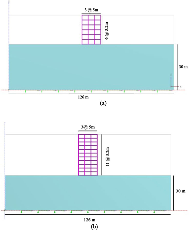
Figure 3. Bare frames of the (a) mid-rise and (b) high-rise structures considered in this study.
Standard bricks were laid to achieve one-brick-thick walls of approximately 230 mm width with mortar joints, which is the standard dimension as per IS 1077:1992 (Indian Standards Institution, 1992) for external and load-bearing walls in traditional Indian masonry construction; therefore, the thickness of the infill wall is given as 230 mm. The base of the structure (raft foundation) was provided at a depth of 2 m below the ground surface, and the thickness of the raft foundation was 0.75 m with plan dimensions of 18 m × 18 m. Six-node beam elements with linear elastoplastic properties were applied as the beam and column elements of the structural models. Although masonry infills exhibit complex non-linear behaviours, including cracking and crushing under seismic loads, we utilised six-node plate elements with elastoplastic properties for the infill walls in this study as these allow representation of the yield behaviours of the infill after reaching the stress limit, thereby providing an understanding of its interactions with the RC frame and soil at the global level. For modelling the raft foundation, we used a six-node plate element with linear elastic properties. The soil elements were represented using 10-node tetrahedral elements, and a live load of 3 kN/m2 and a floor finish of 1 kN/m2 were applied to each model. This study involved 10 distinct types of models, as illustrated in Figure 4. Here, M1/M1H represent regular bare-frame structures without URM infills (Figure 3), whereas the other four models (M2–M5/M2H–M5H) incorporate infilled walls with various opening percentages, such as 20% (Figure 4a), 30% (Figure 4b), 40% (Figure 4c), and 0% (fully infilled; Figure 4d). The nomenclature used to represent the ten models is shown in Table 1, and the material properties are presented in Table 2. Standard assumptions from IS 1905:1987 were used for the masonry infills.
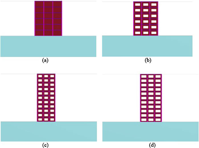
Figure 4. (a) Fully infilled frame (mid-rise); (b) frame with 20% opening (mid-rise); (c) frame with 30% opening (high-rise); and (d) frame with 40% opening (high-rise).
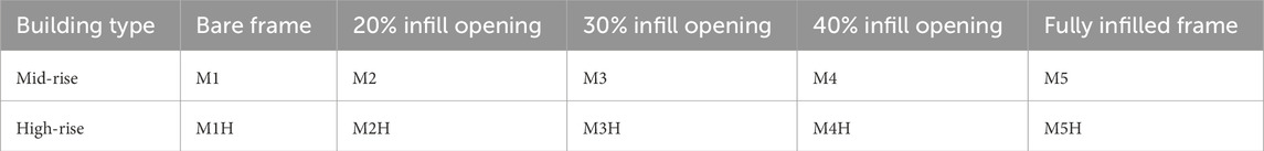
Table 1. Nomenclature for the simulation models used in the present study.
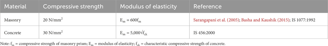
Table 2. Empirical models for compressive strength and elastic modulus.
4 Modelling of infill walls with openings
To capture the impacts of openings in URM infills, we incorporated infilled walls with 20%, 30%, and 40% central openings to represent the practical range observed in typical residential and commercial buildings, as illustrated in Figures 4b–d. The 20% opening simulates standard window configurations, whereas the 30% and 40% configurations reflect larger openings or combinations of windows and doors. These variations are critical because the openings interrupt the load transfer path, reduce the stiffness and strength, and influence crack propagation patterns during seismic excitation. Asteris et al. (2012) demonstrated that increasing the opening percentage transforms infill panels from shear-resisting components to deformable frame-like elements. Therefore, incorporating different opening sizes as considered herein provides a realistic and comparative picture of how infill openings for architectural requirements affect the performances of RC frames. In this study, micro- and macro-modelling of the infills were performed to understand the structural behaviours of these two model types. Macro-modelling was performed using ETABS with an equivalent diagonal compression strut, which is the most widely adopted strut modelling approach. The effective strut width a was obtained using Equation 1 following the procedure from ASCE-41 (or FEMA 356), where
The non-linear behaviours of URM infills with openings under bidirectional seismic excitation are subject to simultaneous in-plane and out-of-plane dynamic loading. Hence, capturing the localised behaviours like cracking patterns, infill crushing, and infill wall buckling is complicated by the numerical (finite element) analysis performed using PLAXIS 3D. Therefore, the global behaviours like displacement, shear force and bending moment concentration pattern, and torsional moments of the infills were examined. The in-plane and out-of-plane behaviours of URM infills with openings were observed using the shear force and torsional moment contours from the numerical analysis.
5 Finite-element modelling of the soil
The finite element software PLAXIS 3D was used for the direct method to simulate the SSI. In this study, we investigated the responses of a six-storey RC structure with and without URM infills resting on a raft foundation on stiff (Type-B/medium) and soft (Type C) soils, as per the seismic loads under IS 1893:2016. The properties of the two types of soils are presented in Table 3. Establishing boundaries for a geometric model is an important aspect of numerical simulation. The boundaries must be positioned such that wave reflection is effectively eliminated. Previous studies have suggested providing lateral boundaries of approximately seven times the raft dimensions from the centre of the raft for soil to effectively mitigate wave reflection; therefore, we used lateral and longitudinal dimensions of 126 m each. A free-field boundary condition was also imposed to ensure that the waves were not absorbed, thereby mimicking an infinite soil medium. Thus, free-field and compliant base boundaries, which are provided to replicate bedrock with adequate interface elements, were established to simulate the soil structure, as shown in Figure 5b. The bedrock depth was 30 m from the ground level. Previous studies have suggested that there are no significant changes in the results when applying coarse-to-very-fine mesh (Jagan and Visuvasam, 2024a); accordingly, a medium mesh was used in this study. Seismic excitations were applied with the prescribed displacements at the bottom of the soil model.
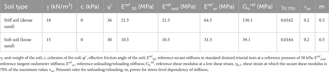
Table 3. Relevant soil parameters (Jagan and Visuvasam, 2024b).
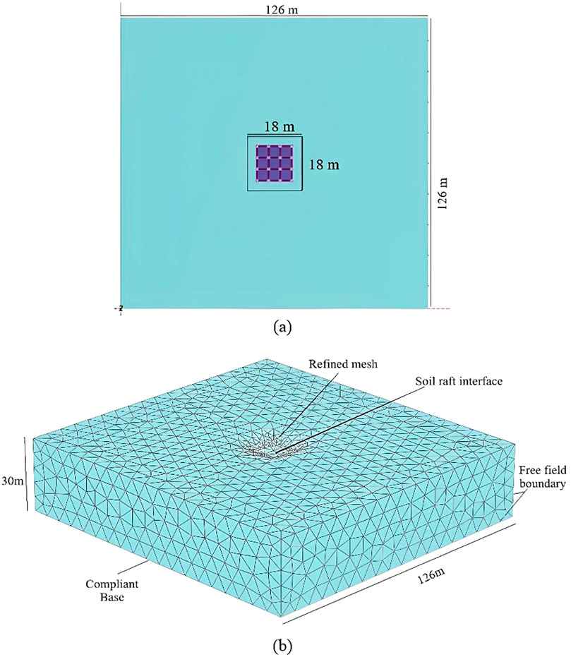
Figure 5. (a) Plan view and (b) 3D model of the soil conditions in this study.
6 Validation
The conditions established by Jagan and Visuvasam (2024b) were used to validate our numerical model to ensure reliability. The structure was modelled in PLAXIS 3D using six-node beam and plate elements with linear elastoplastic properties in hard soil. The model consists of a five-storey concrete frame supported by a raft foundation. The building frame consists of four bays of length 4 m in the x-direction and three bays of length 5 m in the y-direction. The validated model has a total height of 18.5 m, with a ground-storey height of 4.5 m and a per-storey height of 3.5 m for the remaining floors. The beam dimensions used were 0.30 m × 0.45 m, 0.30 m × 0.40 m, and 0.25 m × 0.30, while the corresponding column dimensions were 0.40 m × 0.55 m, 0.40 m × 0.50 m, and 0.35 m × 0.45 m, respectively. The HS model was used to simulate the non-linear behaviours of the soil. The soil properties relevant to the analysis are listed in Table 4. The soil model was given a depth of 30 m; free-field boundaries were used at the lateral boundaries of the soil to reduce wave reflection and replicate the energy dissipation. A compliant base was provided at the bottom to provide earthquake loads through the prescribed surface displacement and defined loading direction. A medium mesh size was used and was locally refined around the raft foundation.
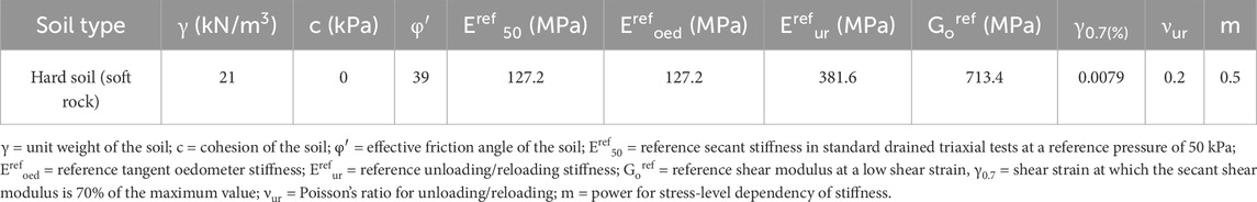
Table 4. Parameters of the HSS model (Jagan and Visuvasam, 2024b).
The NLTHA was conducted to validate a building subjected to an earthquake similar to that at the Imperial Valley-02 recorded at the El Centro Array #9 station. The recorded ground motions were processed and spectrum-matched to the target response spectrum for zone V as per IS 1893:2016 for 5% damping relevant to the validation case using SeismoMatch software (SeismoSoft, 2025). This step ensured that the seismic input applied to the model accurately reflected the intensity and spectral characteristics considered in the validation to assess the efficiency of the non-linear simulation. The model created using PLAXIS 3D is shown in Figure 6a. The material and soil properties used to validate the simulation were taken from Jagan and Visuvasam (2024b). The relative lateral displacement of the validated model is shown in Figure 6b. The validation results showed good agreement with the findings of the reference study. The results from our numerical study give a maximum roof displacement of 17.423 mm, whereas Jagan and Visuvasam (2024b) recorded the roof-storey displacement as 18.5 mm, which is a marginal deviation of 5.3% and indicates a lower percentage of error.
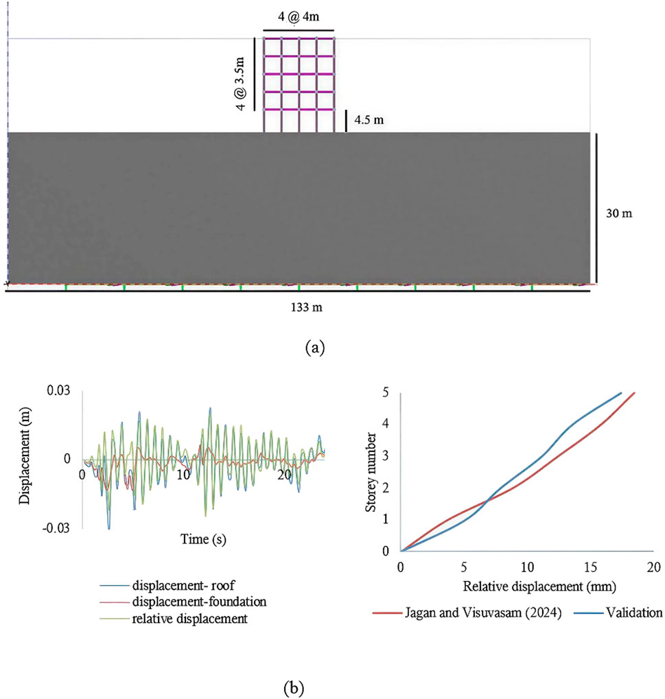
Figure 6. (a) Validation model and (b) relative lateral displacement based on the model.
7 Non-linear time–history analysis
The seismic excitations used for the NLTHA were the ground motions of the 1995 Kobe earthquake sourced from the PEER Ground Motion Database. The selected ground motions were matched to the Indian standard response spectrum curve as per IS 1893:2016 (Part:1) with 5% damping. The matched response spectrum curves are depicted in Figure 7. Spectrum matching was performed using SeismoMatch software. The target design response spectrum from IS 1893:2016 for zone V was first normalised to a peak ground acceleration (PGA) of 1g; the normalised spectrum was then scaled to a PGA of 0.36g to accurately represent the seismic hazard level for zone V as per IS 1893:2016 (Part:1). The original Kobe records were scaled and filtered to ensure that its response spectrum closely matched the target spectrum within the relevant period range. The matched time–history plot (Figure 7) was used to simulate the bidirectional seismic excitations in this study. In bidirectional loading, the seismic excitations were applied simultaneously in two horizontal directions as per the provisions of IS 1893:2016 (Part:1), which specify applying 100% of the design earthquake in one direction and 30% in the orthogonal direction. This approach allows accurate capture of the non-linear and dynamic behaviours of the structure under realistic seismic excitations, especially when considering SSI.
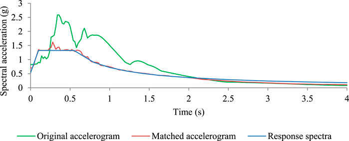
Figure 7. Response spectrum of the ground motions from Kobe earthquake.
8 Results and discussion
Mid-rise and high-rise structures with varying infill openings were analysed in this work using NLTHA. The mode shape, top-storey displacement, storey damage state level, and ISDR were considered parameters to assess the seismic performances of the 10 model configurations considering soft and stiff soils.
8.1 Mode shape
Under bidirectional excitation, the dynamic behaviours of a building with SSI was examined from the mode shape. Buildings with SSI have significantly altered lateral responses through increases in the dynamic time periods of the building. The mode shapes presented in Figure 8 show the effects of SSI on the behaviours of buildings with infill openings situated on different types of soils. For the M1 model (Figure 8a), the mode shape indicates that the SSI amplify the dynamic forces mainly in the structures without additional stiffness; hence, the absence of an infill makes the structure highly vulnerable to the effects of SSI, resulting in large deformations. M5 demonstrated a mode shape with negligible lateral displacement, indicating that the infill stiffness resisted deformation even under the influence of SSI. The partial infills show progressive increases in the deflection patterns with decreases in the overall structural stiffness values. The deflections increase with increasing opening percentages, and this behaviour is consistent in high-rise structures. For structures resting on soft soils, the soil flexibility enhances deflection of the structure more than stiff soil, as observed in Figures 8b–e. Fixed-base structures show more constrained displacement patterns, as seen in Figures 8c,e. When considering flexible soil as the base, the dynamic time period increases, which in turn increases the displacement of the structure. The soft soil allows more intense movements compared to stiff soil; this shows that the effects of SSI are more evident with changes in the soil types. When a structure is situated on soft soil, the impacts of the SSI are more prominent because soft soil is more flexible and allows coupled motions in both of the horizontal directions.
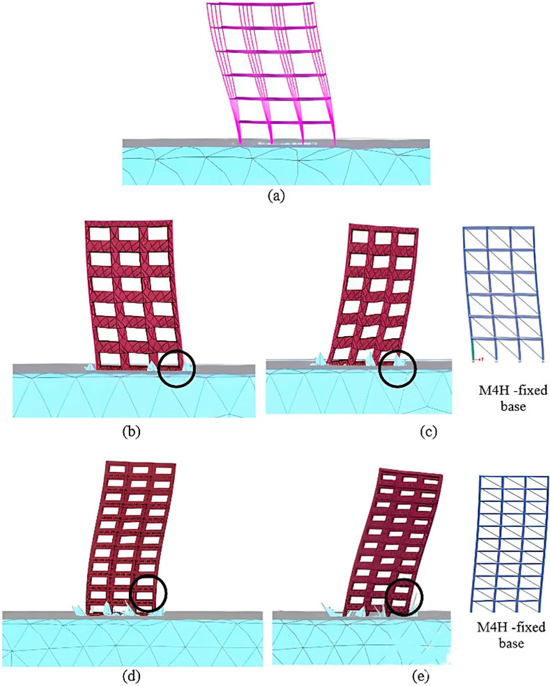
Figure 8. Mode shapes of (a) M1; (b) M4 on stiff soil; (c) M4 on soft soil; (d) M4H on stiff soil; and (e) M4H on soft soil.
8.2 Lateral displacement
Herein, we discuss the absolute and relative displacements of all modelled structures under various base conditions.
8.2.1 Absolute maximum roof displacement
In this study, the absolute displacements of the roof considering SSI were analysed for mid-rise and high-rise structures with varying infill openings resting on stiff and soft soils. The impacts of the SSI on these structures were assessed by comparing the results with those obtained under fixed-base conditions. Using the responses in the x and y directions, the absolute maximum roof displacement was obtained through the square root of the sum of squares (SRSS) method. The amplified values of roof displacement for mid-rise structures in stiff soil compared to identical structures situated on soft soil were 20.7%, 1.5%, 18%, 15.9%, and 11.6% for M1, M4, M3, M2, and M5, respectively, as summarised in Table 5. Similarly, the amplified values of roof displacement for high-rise structures in stiff soil compared to identical structures situated on soft soil were 3.57%, 8.7%, 7.4%, 19.7%, and 0.31% for M1H, M4H, M3H, M2H, and M5H, respectively (Table 6). The comparisons of absolute roof displacements with varying infill opening configurations for soft and stiff soils, as depicted in Tables 5, 6, show significant increases in the top-storey displacements for soft soil than stiff soil. In the presence of SSI, the hardness of the soil, damping properties of the soil, and configuration of the structure influence the manner in which forces are transmitted to the foundation (Asadi Ghoozhdi et al., 2022; Kant et al., 2022). Based on the analysis results, the change in soil type shows increases in the structural displacements, specifically for structures with larger openings, resulting in significant increases in the roof displacements that could affect building performance.
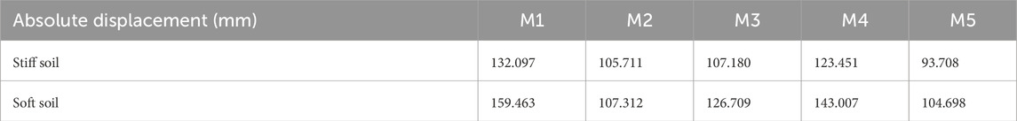
Table 5. Absolute maximum roof displacements for the mid-rise structures.
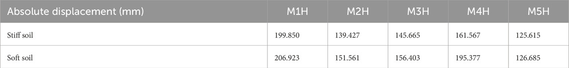
Table 6. Absolute maximum roof displacements for the high-rise structures.
8.2.2 Relative displacement
To determine the effects of SSI, the relative lateral displacements were found by deducting the displacements at the foundation level from the storey-level displacements. In the soft soil condition (Figure 9a), M1 shows a relative displacement of 79.68 mm, with maximum absolute roof and foundation displacements of 127.8 mm and 90.45 mm, respectively. In the stiff soil condition, the maximum absolute displacements of the roof and foundation were 105.71 mm and 84.92 mm, respectively, which yielded a relative lateral roof displacement of 76.18 mm. The relative lateral displacements in stiff soil were 35.2 mm, 33 mm, 56.2 mm, and 14 mm, whereas the values in soft soil were 33.4 mm, 43.2 mm, 69.6 mm, and 17.5 mm for M2, M3, M4, and M5, respectively.
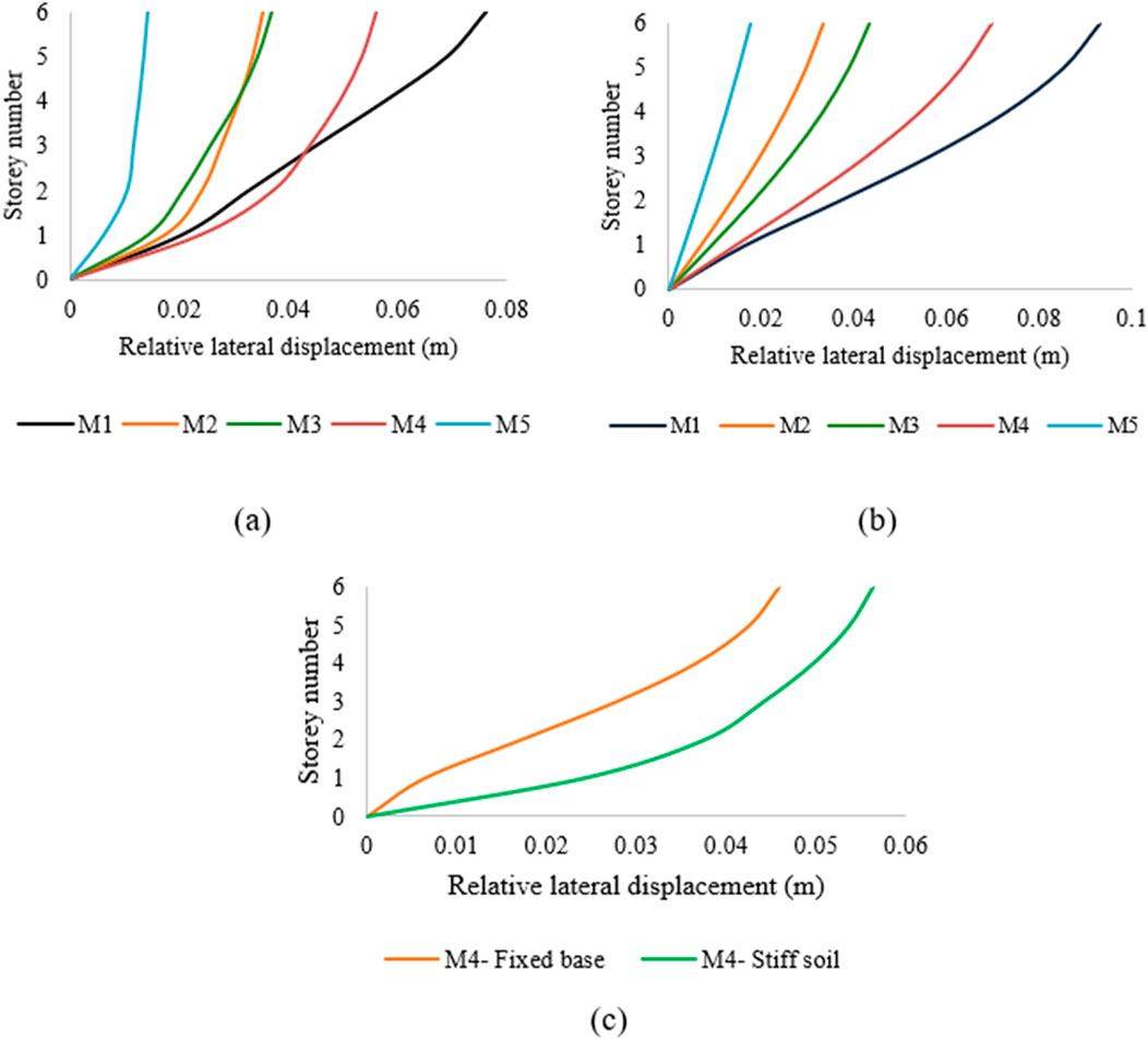
Figure 9. Relative lateral displacements of mid-rise structures resting on (a) stiff and (b) soft soils; (c) comparison between M4 on stiff soil and a fixed base.
It can be observed from Figure 9 that the relative average lateral displacement for mid-rise structures resting on soft soil is higher than or approximately equal to those for structures resting on stiff soil. Mid-rise structures in soft soils show relative displacement amplifications of 22%, −5%, 25.6%, 24%, and 25% for M1, M2, M3, M4, and M5, respectively, compared to structures in stiff soil, as shown in Figures 9a,b. Figure 9c illustrates a comparison of the M4 model with a fixed base and resting on stiff soil. The 5% de-amplification observed for the M2 configuration compared to the positive amplifications of the other configurations (M1, M3, and M4) is attributable to the SSI in terms of the relative displacement when the soil condition changes from stiff to soft. The 20% opening infill panel provides substantial lateral stiffness to the frame, effectively limiting relative displacements of the superstructure. Meanwhile, a foundation resting on soft soil experiences greater displacement owing to the high flexibility of the soil, resulting in large movements of the foundation. Thus, a larger portion of the total displacement occurs at the foundation, reducing the measured relative displacement across the frame itself. It is observed that the structure situated on stiff soil shows a higher lateral displacement of 19.8%.
Figure 10 shows the relative lateral displacement amplifications to be 5%, 8.9%, 2.3%, 18.2%, and 72% for M1H, M2H, M3H, M4H, and M5H, respectively, compared to structures situated in stiff soil (Figures 10a,b). Figure 10c depicts the comparison for M4H with fixed base and stiff soil; it can be observed that the structure on stiff soil shows a higher lateral displacement of 31.3% than that on the fixed base. In both mid-rise and high-rise structures with changing base conditions (fixed base, stiff soil, and soft soil), there were observed increases in the relative lateral storey displacements depending on the flexibility of the base. Similar responses were observed in a study conducted by Wu et al. (2025). Our results demonstrate significant increments in the lateral displacements with changes in base condition from fixed base to stiff and soft soils, emphasising the impact of soil stiffness degradation on the behaviour of the structure due to kinematic interactions. These interactions can cause non-uniform shear and moment distributions along the plan and height directions of the building (Akhtarpour and Mortezaee, 2019). The presence of infill walls with different opening percentages creates structures with varying stiffness, which also influences the lateral displacement. Wani et al. (2022) observed comparable responses for varying structural geometry that could impact the seismic responses in structures whose bases are influenced by SSI.
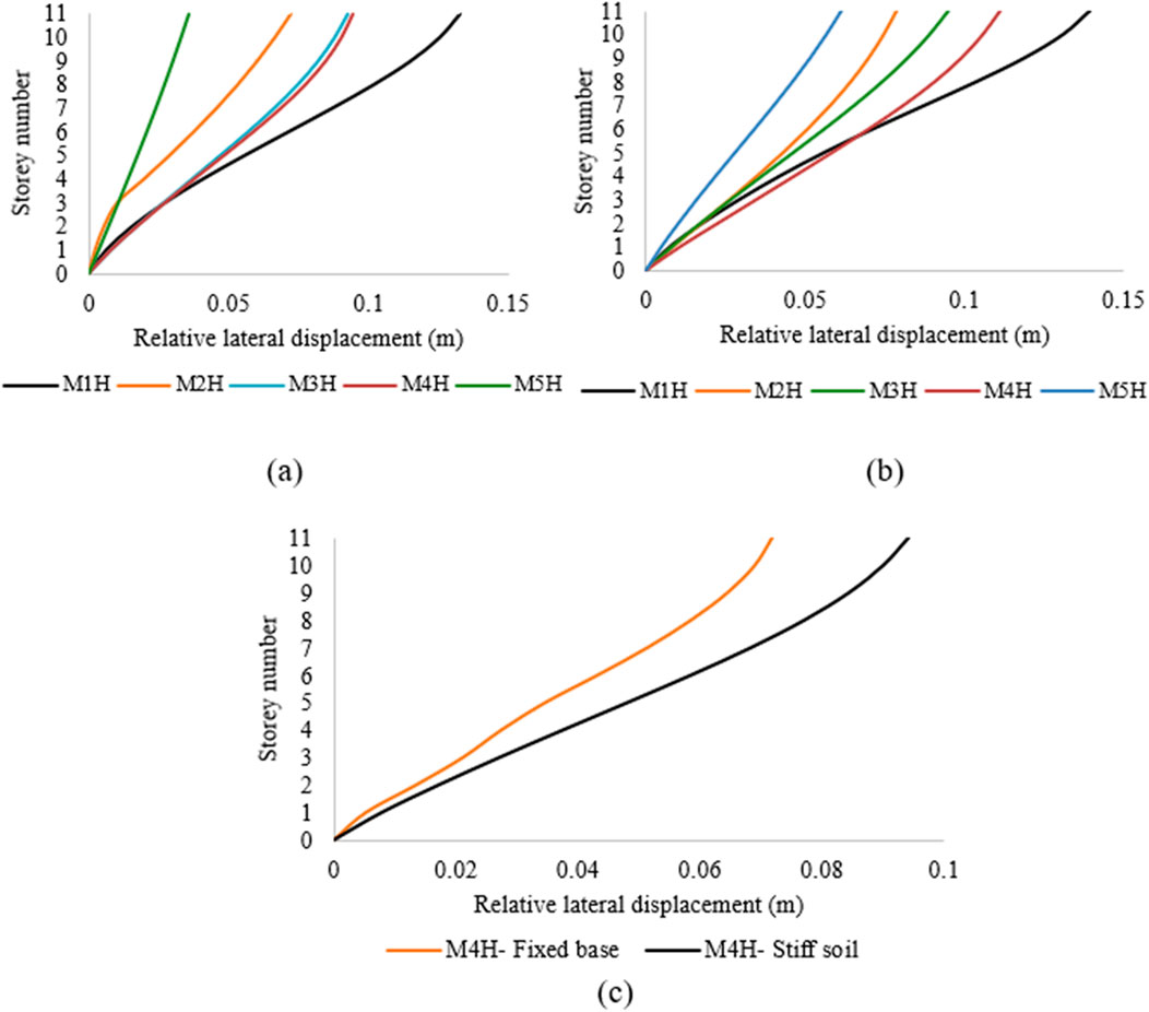
Figure 10. Relative lateral displacements of high-rise structures resting on (a) stiff and (b) soft soils; (c) comparison between M4H on stiff soil and a fixed base.
8.3 HAZUS damage state assessment
The damage state level of each storey was determined using the HAZUS methodology (Federal Emergency Management Agency, 2007). The damage state level was assessed with respect to storey drift as the demand parameter. The storey drift threshold for each damage state level, such as slight, moderate, extensive, and complete, is provided for C1M (mid-rise concrete-moment frame) and C1H (high-rise concrete-moment frame) type buildings in the HAZUS MH MR-4. For C1M, the building damage thresholds adopted from HAZUS are 0.0033 (slight), 0.0067 (moderate), 0.0200 (extensive), and 0.0533 (complete). For C1H, the building damage thresholds adopted from HAZUS are 0.0025 (slight), 0.005 (moderate), 0.0150 (extensive), and 0.04 (complete).
It was observed that for mid-rise structures on stiff soil, the bottom storey of M2 experienced moderate damage while the top storey sustained slight damage. The damage states for varying infill configurations under stiff soil conditions are depicted in Figure 11a. In the case of M3, all stories showed moderate damage, whereas M4 showed extensive damage at the bottom storey and moderate damage at the top storey. The damage concentrations were critical in the M1 and M4 models. As the infill wall openings decreased, the damage distribution became more uniform, with the upper stories primarily experiencing slight-to-moderate damage. The M5 configuration shows a substantial reduction in drift beyond the first storey, indicating enhanced stiffness that restricts damage propagation. For the same mid-rise structures resting on soft soil, the bottom storey of M3 showed extensive damage (Figure 11b); in the M4 case where only the bottom storey experienced extensive damage on stiff soil, there was extensive damage to all storeys except for the top storey on soft soil, which sustained moderate damage. Even in the M2 configuration, there was moderate damage to all stories in soft soil except the top storey. Previous studies have reported that lateral stiffness and SSI have significant impacts on the seismic performances of mid-rise structures (Firoj et al., 2022). The high-rise structures showed increased storey drift for M1H, with the intermediate stories sustaining complete damage in both soft and stiff soils, as shown in Figures 11c, d; however, the top storey of M1H on stiff soil showed only slight damage. M5H sustained slight-to-moderate damage in stiff soil, but showed moderate damage for all stories on soft soil. M2H and M3H exhibited moderate damage for all floors on soft soil, while the top stories experienced moderate damage on stiff soil.
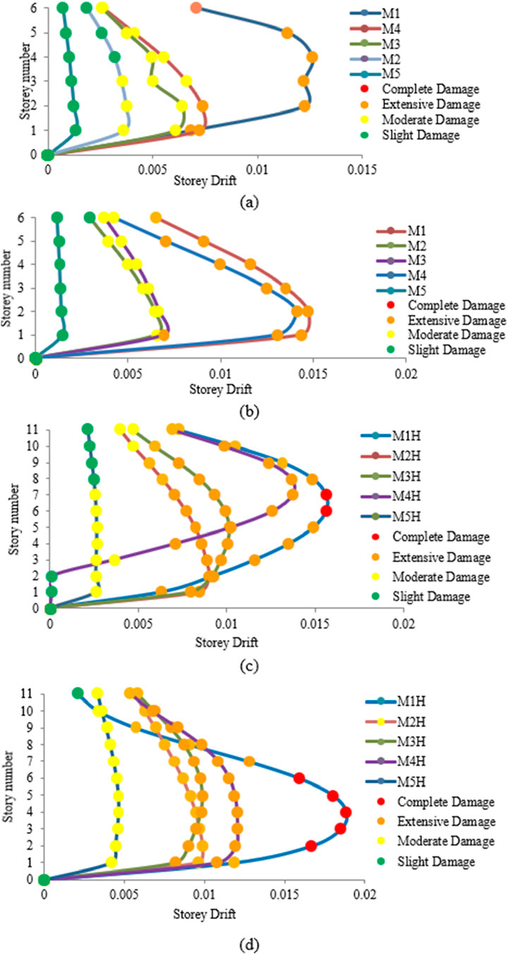
Figure 11. Damage states of mid-rise and high-rise structures resting on (a, c) stiff and (b, d) soft soils, respectively.
HAZUS MH MR-4 describes four damage states as slight, moderate, extensive, and complete. In IS 1893:2016 (Part-1), these states are classified into five grades, namely slight, moderate, heavy, destruction, and total damage. Slight damage indicates fine cracks in the plaster with flexural or shear-type hairline cracks in some beams and joints. Moderate damage implies fine cracks in the walls as well as hairline cracks in most beams and columns, along with falling of plaster. In the extensive/heavy damage state, there are large and deep cracks in the walls, with some frame elements reaching their ultimate capacities. Grades 4 and 5 (destruction and total damage) of the damage states under IS 1893:2016 (Part-1) are combined in HAZUS under complete damage, indicating that there are very large cracks in the walls and that the structure has collapsed or has an imminent chance of collapse if 10% (for mid-rise) or 5% (for high-rise) of the total area of a C1 building with complete damage is present.
For all the fixed-base models, the drifts remained in the moderate damage state. In the case of mid-rise structures, the maximum drift values for M4 considering SSI were 0.0073 for stiff soil and 0.014 for soft soil, which are within the extensive damage range, whereas the value of the fixed base was in the slight-to-moderate damage state (0.00351), as shown in Figure 12a. For high-rise structures, the maximum drift values were 0.012 for stiff soil and 0.014 for soft soil, which are within the extensive damage range, whereas the value of the fixed base was in the slight-to-moderate damage state (0.00362), as shown in Figure 12b. This demonstrates the importance of considering SSI in safe structural design and also indicates that the fixed-base case underestimates the damage state of the structure.
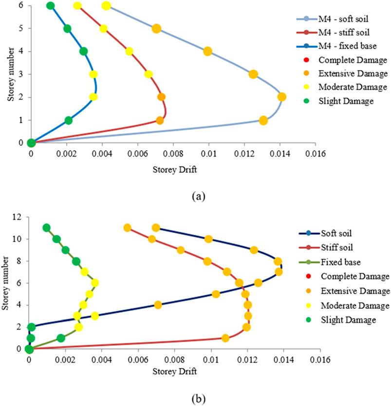
Figure 12. Damage states of the (a) M4 and (b) M4H models with structure–soil interactions (SSI) when situated on a fixed base.
8.4 Inter-storey drift ratio
In this study, the ISDR values of mid-rise and high-rise structures were assessed for all infill configurations for both fixed and flexible base conditions. The ISDRs considering SSI for each soil condition (stiff and soft) across the various infill configurations of the mid-rise and high-rise structures are illustrated in Figure 13. From Figures 13a, b, it can be observed that there are 45%, 65.5%, 45%, 65%, and 11.9% reductions in ISDRs on stiff soil for the M1, M2, M3, M4, and M5 models, respectively, compared to those on soft soil. For the high-rise models, there were ISDR amplifications of 21%, 27.9%, 2.5%, 25.6%, and 61.9% for M1H, M2H, M3H, M4H, and M5H, respectively, for the models on soft soil compared to stiff soil (Figures 13c, d). Comparisons of the ISDRs between the M1 and M4 as well as M1H and M4H structures with fixed bases and SSI under the two soil conditions show that when SSI effects are added to the fixed base models, the ISDRs of the structures are amplified. Compared to the fixed-base models, the drift values were amplified by 6.25 and 5.95 times for M1 and M4 on stiff soil. The comparison between structures on soft soil and fixed base demonstrated drift amplifications of 6.56 and 5.74 times for M1 and M4 on soft soil. In the case of high-rise structures, there were drift amplifications of 5.19 and 6 times on soft soil as well as 5.15 and 4.7 times on stiff soil for the M1H and M4H models, respectively, compared to the fixed-base models. It is evident from these results that the ISDR tends to increase when considering the non-linear behaviours of the soils. We note that the peak ISDRs were noted along the second and third stories for the fixed-base structures. In the case of the SSI-incorporated models, peak ISDRs were noted at the bottom storey for most of the infilled models. Our study demonstrates this variation in the ISDR curves for the SSI-incorporated models, indicating that the presence of SSI can lead to uneven distribution of the ISDRs. These variations in the drift curves in the different models under SSI reflect the added flexibility provided by the soil, which allows different deformation patterns compared with the constrained movements of the fixed-base structures.

Figure 13. Inter-storey drift ratios of mid-rise and high-rise structures resting on (a, c) soft and (b, d) stiff soils, respectively.
8.5 Shear force and bending moment
Five infill configurations of the mid-rise and high-rise structures were analysed for shear force, bending moment, and torsional moment. The shear force contours depicted in Figure 12 show that the infill walls with openings (M4 and M4H) experience higher shear concentrations, particularly near the edges and openings. In M4 on stiff soil, the shear forces reach maximum concentration near the discontinuities in the infill, whereas the same model on soft soil shows more scattered force concentrations. In models M4 and M4H, these concentrations indicate potential vulnerabilities at the edges, openings, or beam column joints. Similar shear patterns were observed for the other models with openings (M2 and M3). For M5 on stiff soil, the shear was observed to be maximum along the corner joints and diagonal to the infills, whereas the force distribution is more even on soft soil and the force concentration near the edges on the bottom storey are due to the added flexibility in soft soil. In M5H, the shear distribution is more uniform across the elevation, with slightly higher concentrations in the bottom stories, similar to the M5 model. The absence of openings can result in better shear transfer through the walls. In soft soil, M5H shows a clearer contour with concentrated shear values at the base and joints. For models with openings (M2, M3, M4, M2H, M3H, and M4H), the force concentrations are more irregular and scattered around the openings.
The bending moments are distributed and concentrated mostly at the base and roof levels for all models. For models with openings (M4), concentration of the bending moment is observed along the corners of the openings. The presence of openings creates discontinuities, increasing the flexural demand near the corners. There are no openings in the M5/M5H models, and the moment concentrations are seen between the joints in two adjacent stories in these cases. For high-rise models, the moment distributions are more even throughout the height direction compared to the mid-rise models, and this behaviour is observed on both soil types.
There are significant torsional moments in all modelled structures, especially near the joints and openings, as shown in Figures 14, 15. In the M5/M5H configurations on stiff soil, the torsional moments are comparatively low owing to the symmetrical and continuous nature of the infills with minimal localised torsion. However, the same structures on soft soil show increased torsional moments along the top and bottom stories of the structures as well as along the joints along the height direction owing to the added flexibility of the soil that enables more torsion than stiff soil. In structures with openings like M4/M4H, the maximum torsional moments are observed along the corners of the infill openings, indicating more localised torsion.
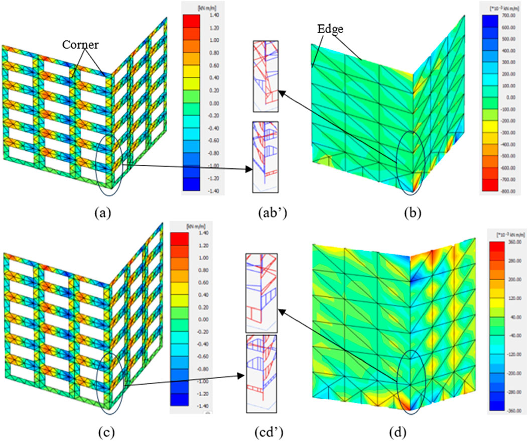
Figure 14. Torsional moments at the infills of (a) M4 on stiff soil, (b) M5 on stiff soil, (c) M4 on soft soil, and (d) M5 on soft soil as well as at the columns of M4 and M5 on (ab’) stiff and (cd’) soft soils.
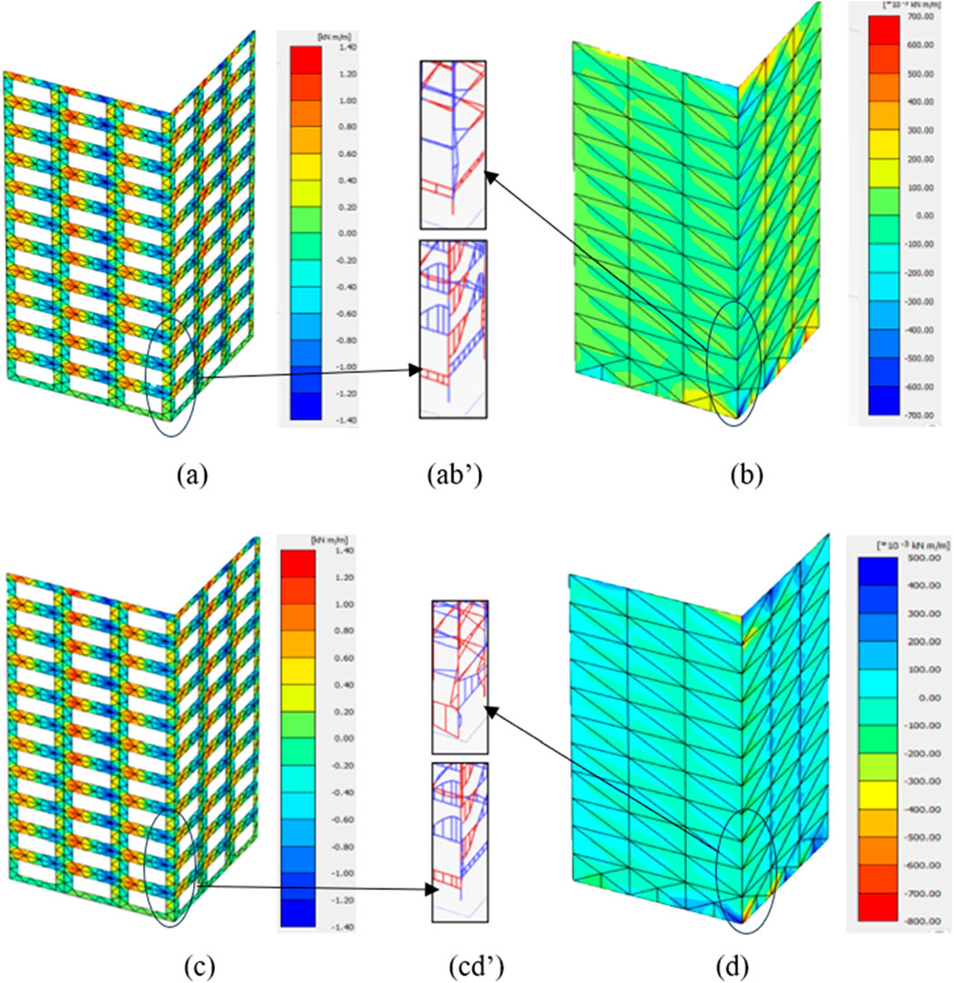
Figure 15. Torsional moments at the infills of (a) M4H on stiff soil, (b) M5H on stiff soil, (c) M4H on soft soil, and (d) M5H on soft soil as well as at the columns of M4H and M5H on (ab’) stiff and (cd’) soft soils.
From the contours of the shear force, bending moment, and torsional moment, it is evident that structures with openings have a greater concentration of these forces around the openings/discontinuities in the infill. This means that having openings in the infill can modify the load path, making the structure susceptible to diagonal cracks/shear failure or bending failure due to excessive concentration of forces around the openings. The soil type also plays an important role in these force and moment distributions/concentrations. Soft soil has more flexibility and enables foundation movement, which in turn amplifies the structural movements and results in more twisting or displacement of the structure; this can increase the chances of shear failure/bending failure in infills, which are generally overlooked when neglecting the impacts of SSI.
The distributions of the internal actions are aligned with the observed damage patterns across various configurations. In models with openings, such as M4 and M4H, higher shear concentrations were observed around the edges and corners, matching the locations where diagonal cracking and partial infill collapse were observed during damage assessment. The concentration of bending moments near the corners of openings in these models explains the flexural cracking and localised crushing in the surrounding masonry units. In M2 and M3 that had smaller openings, the shear forces were more dispersed but still intensified near the discontinuities, consistent with the moderate cracking patterns in these regions. The fully infilled configurations (M5 and M5H) exhibited maximum shear along the corner joints and diagonally, corresponding to the observed diagonal cracking without complete infill failure. In the high-rise cases, the moment distributions were more uniform and aligned with the more distributed damage observed across multiple stories rather than being concentrated at specific locations. Overall, the areas experiencing high shear forces are correlated with diagonal cracking and potential shear failure, while high bending moments correspond to localised flexural damage, demonstrating that the internal action contours provide a reliable indicator of the severity and locations of the observed structural and non-structural damages.
9 Conclusion
This study presents an investigation of the impact of SSI on infill wall openings in URM-infilled RC buildings with varying heights and soil conditions. A six-storey mid-rise and an eleven-storey high-rise building with various realistic opening percentages like 20%, 30%, and 40% (indicated as M2, M3, and M4 for mid-rise and M2H, M3H, and M4H for high-rise, respectively) were considered in the study along with a bare frame (M1/M1H) and a fully infilled frame (M5/M5H). Dynamic analysis was then performed considering bidirectional loading under stiff and soft soil conditions. We propose some necessary performance assessment parameters like the maximum roof displacement, ISDR, mode shape, and damage state level that must be considered for better optimisation of the infill opening percentage. From the analysis results, the following conclusions are drawn.
1. From the mode shape, it is evident that there are differences in the displacements under various soil types, indicating the risk of underestimating the impacts of dynamic loading on the structure when SSI are neglected. The fixed-base condition constrains foundation movement, misleading the overall structural deformation. The analysis revealed that the 40% infill opening case (M4 and M4H) shows significant change in the dynamic mode shape pattern under soft soil condition. Constraints in the mode shape pattern were observed in case of fixed-base analysis, indicating that infill opening with SFS modelling has significant impacts over the dynamic modal time period of the structure.
2. The shear force and bending moment contours indicate higher concentrations of forces around the openings of the infills. The openings in the infill walls alter the infill–frame interactions, making the structures more susceptible to shear and torsional failure, especially in the case of high-rise buildings on soft soil.
3. Bidirectional loading can cause both in-plane and out-of-plane failures under both soil conditions. Although the in-plane failure was predominant in all URM infill opening cases, minor out-of-plane failure patterns were observed from the torsional moment contours. The 40% infill opening cases (M4 and M4H) showed significant increases in the torsional moments than the other cases. This shows that the higher opening percentage can lead to out-of-plane behaviours, especially under bidirectional loading. Under changes in the soil type, the force and moment concentrations shifted; the structures on soft soil showed scattered forces and moment contours than on stiff soil.
4. SSI significantly increase the lateral storey displacements and ISDRs for both mid-rise and high-rise structures compared to the fixed-based condition. Mid-rise structure on soft soil show relative displacement amplifications of 25.6% and 24% for M3 and M4, respectively, than on stiff soil. The relative lateral displacements for high-rise structures on soft soils showed amplifications of 2.3% and 18.2% for M3H and M4H, respectively, and the structure on stiff soil showed a higher lateral displacement of 31.3% compared to that on a fixed base, demonstrating the significance of SSI under bidirectional seismic excitation.
5. Damage state assessment at each storey level showed significant increases with the infill opening percentages and height of the building, especially under soft soil conditions. In high-rise buildings, almost all the stories in M3H and M4H reached extensive damage state levels under soft soil conditions. On stiff soil, M3H and M4H sustained only moderate-to-extensive damage state levels. In mid-rise buildings, M3 and M4 reached moderate and extensive damage state levels, respectively, under soft soil conditions, whereas they achieved moderate damage state levels under stiff soil conditions.
6. The fixed-based condition underestimates the storey damage state level, leading to improper capture of the building responses. For the mid-rise M4 configuration, the fixed-base model underestimates damage by indicating a slight-to-moderate drift (0.00351), whereas the SSI-incorporated model shows extensive damage with a drift of 0.0073 on stiff soil and 0.014 on soft soil.
7. Based on the performance assessment parameters and by accounting for the damage state level, storey drift, and soil conditions, the optimum infill opening percentages for the buildings considered in this study were estimated to be 30% for mid-rise and 20% under critical (soft) soil conditions.
We thus conclude that the optimum infill opening percentages vary significantly based on the soil type, building height, and dynamic loading conditions. The SFS modelling approach has important implications for URM-infilled buildings, especially those located in areas that are prone to high seismic activities, as the openings in the infills significantly affects the dynamic characteristics of these buildings. The performance assessment parameters proposed herein were found to be satisfactory for optimising the infill opening percentages of structures located in seismically prone areas.
10 Limitations and future scope
The findings of the present study are limited to symmetrical RC structures on homogenous soil types. Thus, different irregularities must be considered when deriving generalised guidelines for openings in URM-infilled structures. In the future, studies on the effects of cyclic degradations and out-of-plane instabilities, fragility analysis, and progressive collapse on layered soils are suggested to derive greater insights on and more accurate behaviours of URM-infilled structures.
Data availability statement
The raw data supporting the conclusions of this article will be made available by the authors without undue reservation.
Author contributions
NA: Data curation, Conceptualization, Software, Methodology, Formal analysis, Visualization, Writing – original draft. SP: Data curation, Project administration, Resources, Validation, Supervision, Writing – review and editing.
Funding
The author(s) declare that no financial support was received for the research and/or publication of this article.
Acknowledgments
The authors wish to thank Vellore Institute of Technology (Vellore) for providing support and the necessary facilities for this research work.
Conflict of interest
The authors declare that the research was conducted in the absence of any commercial or financial relationships that could be construed as a potential conflict of interest.
Generative AI statement
The author(s) declare that no Generative AI was used in the creation of this manuscript.
Any alternative text (alt text) provided alongside figures in this article has been generated by Frontiers with the support of artificial intelligence and reasonable efforts have been made to ensure accuracy, including review by the authors wherever possible. If you identify any issues, please contact us.
Publisher’s note
All claims expressed in this article are solely those of the authors and do not necessarily represent those of their affiliated organizations, or those of the publisher, the editors and the reviewers. Any product that may be evaluated in this article, or claim that may be made by its manufacturer, is not guaranteed or endorsed by the publisher.
References
Ahiwale, D., Patil, A. N., and Kontoni, D. P. N. (2024). Quantification and parametric analysis of large overhang RC planar frames subjected to horizontal and combined horizontal–vertical earthquake loading. Asian J. Civ. Eng. 26, 401–430. doi:10.1007/s42107-024-01197-4
Akhtarpour, A., and Mortezaee, M. (2019). Dynamic response of a tall building next to deep excavation considering soil-structure interaction. Asian J. Civ. Eng. 20 (4), 479–502. doi:10.1007/s42107-018-0078-4
Alhalil, F., and Gullu, M. F. (2023). Investigating infill wall configurations on 3-D structural systems with a generalized modeling approach. Arabian J. Sci. Eng. 48 (10), 13523–13551. doi:10.1007/s13369-023-07914-6
Amico, L., Nicoletti, V., Martini, R., Carbonari, S., and Gara, F. (2025). Impact of combined seismic and energy renovation works on the dynamics and damageability of infilled RC frame buildings. J. Build. Eng. 104, 112169. doi:10.1016/j.jobe.2025.112169
Anić, F., Penava, D., Abrahamczyk, L., and Sarhosis, V. (2024). On the mechanical behaviour of masonry infilled RC frames, with and without openings, subjected to simultaneous in-plane (IP) and out-of-plane (OoP) loading. Bull. Earthq. Eng. 22 (4), 1775–1799. doi:10.1007/s10518-023-01832-6
Anwar, M. Y., Peloso, S., and Brunesi, E. (2025). Test-informed in-plane/out-of-plane capacity domain-driven seismic fragility models for masonry infills in reinforced concrete frames. Structures 76, 109014. doi:10.1016/j.istruc.2025.109014
Asadi Ghoozhdi, R., Attarnejad, A., Masoodi, A. R., and Majlesi, A. (2022). Seismic assessment of irregular RC frames with tall ground story incorporating nonlinear soil–structure interaction. Structures 41, 159–172. doi:10.1016/j.istruc.2022.05.001
Asteris, P. G., Giannopoulos, I. P., and Chrysostomou, C. Z. (2012). Modeling of infilled frames with openings. Open Constr. Build. Technol. J. 6 (1), 81–91. doi:10.2174/1874836801206010081
Baghi, H., Oliveira, A., Valença, J., Cavaco, E., Neves, L., and Júlio, E. (2018). Behavior of reinforced concrete frame with masonry infill wall subjected to vertical load. Eng. Struct. 171, 476–487. doi:10.1016/j.engstruct.2018.06.001
Bapir, L. A., Wichtmann, T., and Prada-Sarmiento, L. F. (2023). Soil-structure interaction: a state-of-the-art review of modeling techniques and studies on seismic response of building structures. Front. Built Environ. 9, 1120351. doi:10.3389/fbuil.2023.1120351
Basha, S. H., and Kaushik, H. B. (2015). Evaluation of nonlinear material properties of fly ash brick masonry under compression and shear. J. Mater. Civ. Eng. 27 (8), 04014227. doi:10.1061/(asce)mt.1943-5533.0001188
Bentley Systems (2024). PLAXIS 3D (version 2024.2). Computer software. Available online at: https://www.plaxis.com (Accessed May 7, 2025).
Biradar, B. B., Rc, B., and Shirkol, A. I. (2022). Comparative study and performance evaluation of steel moment resisting frames design with: force-based design and performance-based plastic design. Structures 43, 696–709. doi:10.1016/j.istruc.2022.07.001
Biradar, B. B., Hakeem, M., Rc, B., and Shirkol, A. I. (2025). Performance evaluation of eccentrically braced frames by strength based and performance based plastic design methods considering Turkey’s ground motions. Iran. J. Sci. Technol. Trans. Civ. Eng. doi:10.1007/s40996-025-01804-7
Brodsky (2021). A micro–macro modelling methodology for the analysis of infilled frames. Bull. Earthq. Eng. 19 (5), 2161–2184. doi:10.1007/s10518-021-01045-9
Buch, S. H., Bhat, J. A., Bhat, M. D., and Mirza, M. I. (2025). Seismic behavior of RC frames with choh-kat openings: a novel strut model approach. Bull. Earthq. Eng. 23 (4), 1639–1676. doi:10.1007/s10518-025-02112-1
Bureau of Indian Standards (2016). IS 1893 (Part 1): 2016 – criteria for earthquake resistant design of structures – Part 1: general provisions and buildings. New Delhi: BIS.
Bush, V., Rani, V., Suleiman, M. F., Biradar, B. B., Vyas, R., Ahmad, A., et al. (2024). Seismic performance evaluation and comparative study of reinforced concrete building on a sloped terrain with regular building by considering the effect of URM infill walls. Buildings 14 (1)–33. doi:10.3390/buildings14010033
Chakraborty, A., Bhattacharya, K., and Sawant, V. A. (2024). Soil structure interaction effects on multistorey asymmetric building subjected to earthquake loading. Indian Geotechnical J. 55, 303–314. doi:10.1007/s40098-024-00938-1
Computers and Structures, Inc. (2020). ETABS ultimate (version 20.0.0). Computer software. Available online at: https://www.csiamerica.com/products/etabs (Accessed May 7, 2025).
Crisafulli, F. J., and Carr, A. J. (2007). Proposed macro-model for the analysis of infilled frame structures. Bull. N. Z. Soc. Earthq. Eng. 40 (2), 69–77. doi:10.5459/bnzsee.40.2.69-77
Das, S., and Maheshwari, B. K. (2024). Influence of slope topography on soil-structure interaction during earthquakes. Acta Geotech. 19, 4715–4730. doi:10.1007/s11440-023-02186-8
Debbarma, R., and Verma, Y. (2025). Effect of soil flexibility on seismic response of setback RC buildings considering raft foundation. Innov. Infrastruct. Solutions 10 (3), 81. doi:10.1007/s41062-024-01820-y
Di Trapani, F., Bertagnoli, G., Marco, F. F., and Gino, D. (2018). Empirical equations for the direct definition of stress-strain laws for fiber-section-based macromodeling of infilled frames. J. Eng. Mech. 144 (11), 04018101. doi:10.1061/(ASCE)EM.1943-7889.0001532
Di Trapani, F., di Benedetto, M., Petracca, M., and Camata, G. (2024). Local infill-frame interaction under seismic loads: Investigation through refined micro-modeling. Eng. Struct. 315, 118088. doi:10.1016/j.engstruct.2024.118088
Ekrami Kakhki, S. A., Kheyroddin, A., and Mortezaei, A. (2023). Numerical investigation of the progressive collapse of the reinforced concrete wall-frame structures considering the soil–structure interaction. Int. J. Concr. Struct. Mater. 17 (1), 22. doi:10.1186/s40069-022-00575-z
El-Kholy, A. M., Sayed, S. M., and El-Assaly, M. M. (2024). Nonlinear macromodeling of multistory RC buildings with masonry infill walls. Bull. Earthq. Eng. 22 (3), 1451–1484. doi:10.1007/s10518-023-01787-8
El-Nemr, M. T., Azzam, W. R., Abu-Raia, M. M., and Wahba, M. A. (2024). Beneficial effects of infill walls on the structure and foundation lateral performance under the effect of seismic loads. Civ. Eng. 3 (3), 383. doi:10.1007/s42107-024-01025-9
Federal Emergency Management Agency (FEMA) (2007). HAZUS-MH MR4 Technical manual – earthquake model. Washington, D.C.: Department of Homeland Security.
Feng, D. C., Zhang, M. X., Brunesi, E., Parisi, F., Yu, J., and Zhou, Z. (2022). Investigation of 3D effects on dynamic progressive collapse resistance of RC structures considering slabs and infill walls. J. Build. Eng. 54, 104421. doi:10.1016/j.jobe.2022.104421
Firoj, M., Bahuguna, A., Kanth, A., and Agrahari, R. (2022). Effect of nonlinear soil–structure interaction and lateral stiffness on seismic performance of mid-rise RC building. J. Build. Eng. 59, 105096. doi:10.1016/j.jobe.2022.105096
Forcellini, D. (2022). Seismic fragility of tall buildings considering soil structure interaction (SSI) effects. Structures 45, 999–1011. doi:10.1016/j.istruc.2022.09.070
Furtado, H., Rodrigues, H., and Arêde, A. (2015). Modelling of masonry infill walls dparticipation in the seismic behaviour of RC buildings using OpenSees. Int. J. Adv. Struct. Eng. 7 (2), 117–127. doi:10.1007/s40091-015-0086-5
Furtado, H., Rodrigues, H., and Arêde, A. (2022). Effect of the openings on the seismic response of an infilled reinforced concrete structure. Buildings 12 (11), 2020. doi:10.3390/buildings12112020
Gaile, L., Ratnika, L., and Pakrastins, L. (2022). RC medium-rise building damage sensitivity with SSI effect. Materials 15 (5), 1653. doi:10.3390/ma15051653
Guettala, S., Abdesselam, I., Khelaifia, A., and Chebili, R. (2024a). Advances in macro modeling for seismic performance assessment of infilled reinforced concrete structures. Asian J. Civ. Eng. 26, 1009–1022. doi:10.1007/s42107-024-01236-0
Guettala, S., Abdesselam, I., and Chebili, R. (2024b). Assessment of the effects of infill walls’ layout in plan and/or elevation on the seismic performance of 3D reinforced concrete structures. Asian J. Civ. Eng. 25 (1), 657–673. doi:10.1007/s42107-023-00802-2
Holmes, M. (1961). Steel frames with brickwork and concrete infilling. Proc. Institution Civ. Eng. 19 (4), 473–478. doi:10.1680/iicep.1961.11305
Ibrahim, A. R., Makhloof, D. A., and Ren, X. (2024). Seismic performance and collapse analysis of RC framed-wall structure excited with Turkey/Syria destructive earthquake. Structures 59, 105774. doi:10.1016/j.istruc.2023.105774
Indian Standards Institution (1992). IS 1077: Common Burnt Clay building Bricks—Specification. New Delhi (India): Bureau of Indian Standards.
Jagan, P., and Visuvasam, J. (2024a). Assessment of the influence of nonlinear soil effects on seismic response of RC structures with floating columns considering soil–structure interaction. Geomatics Nat. Hazards Risk 15, 2401997. doi:10.1080/19475705.2024.2401997
Jagan, P., and Visuvasam, J. (2024b). Effects of soil small strain nonlinearity on the dynamic behavior of floating column structures considering soil-structure interaction. Innov. Infrastruct. Solutions 9, 228. doi:10.1007/s41062-024-01523-4
Jia, M., Kong, J., and Wu, J. (2024). A double-strut macro-modelling approach for the in-plane analysis of masonry infilled RC frames with openings. Bull. Earthq. Eng. 22 (5), 2469–2504. doi:10.1007/s10518-024-01860-w
Kamal, M., Inel, M., and Cayci, B. T. (2022). Seismic behavior of mid-rise reinforced concrete adjacent buildings considering soil-structure interaction. J. Build. Eng. 51, 104296. doi:10.1016/j.jobe.2022.104296
Kant, R., Al-Agha, W., Almorad, W. A., Thakur, M. S., and Umamaheswari, N. (2022). Study on seismic performance of reinforced concrete multi-storey building considering soil-structure inter-action effect. Mater. Today Proc. 56, 2158–2166. doi:10.1016/j.matpr.2021.11.475
Karki, P., Pyakurel, S., and Utkarsh, K. (2023). Seismic performance evaluation of masonry infill R.C. Frame considering soil-structure interaction. Innov. Infrastruct. Solutions 8 (1), 5. doi:10.1007/s41062-022-00979-6
Kazemi, F., Asgarkhani, N., and Jankowski, R. (2023). Probabilistic assessment of SMRFs with infill masonry walls incorporating nonlinear soil-structure interaction. Bull. Earthq. Eng. 21 (1), 503–534. doi:10.1007/s10518-022-01547-0
Kurmi, P. L., and Haldar, P. (2022). Modeling of opening for realistic assessment of infilled RC frame buildings. Structures 41, 1700–1709. doi:10.1016/j.istruc.2022.05.110
Kurmi, P. L., and Haldar, P. (2025). Seismic evaluation of open ground storey RC buildings with realistic functional openings in upper storey infills. Structures 72, 108214. doi:10.1016/j.istruc.2025.108214
Liu, Z., and Crewe, A. (2020). Effects of size and position of openings on in-plane capacity of unreinforced masonry walls. Bull. Earthq. Eng. 18 (10), 4783–4812. doi:10.1007/s10518-020-00894-0
Louzai, A., and Abed, A. (2021). Concentric versus eccentric strut models in the seismic response of masonry infilled reinforced concrete frame structures using nonlinear dynamic analysis. Nat. Hazards 106 (3), 2111–2137. doi:10.1007/s11069-021-04532-z
Mainstone, R. J., and Weeks, G. A. (1972). “The influence of a bounding frame on the Racking Stiffnesses and strengths of brick walls,” in 2nd international brick masonry conference, Watford.
Messaoudi, A., Chebili, R., Mohamed, H., and Rodrigues, H. (2022). Influence of masonry infill wall position and openings in the seismic response of reinforced concrete frames. Appl. Sci. 12 (19), 9477. doi:10.3390/app12199477
Mohamed, H., and Romão, X. (2020). Analysis of the performance of strut models to simulate the seismic behaviour of masonry infills in partially infilled RC frames. Eng. Struct. 222, 111124. doi:10.1016/j.engstruct.2020.111124
Moreira, R. F., Varum, H., and Castro, J. M. (2023). Influence of masonry infill walls on the seismic assessment of non-seismically designed RC framed structures. Buildings 13 (5), 1148. doi:10.3390/buildings13051148
Negrin, M. K., and Yepes, V. (2025). Metamodel-assisted design optimization of robust-to-progressive-collapse RC frame buildings considering the impact of floor slabs, infill walls, and SSI implementation. Eng. Struct. 325, 119487. doi:10.1016/j.engstruct.2024.119487
Oz, I. (2025). Seismic pounding effects of typical midrise reinforced concrete structures subjected to soil–structure interaction effects. J. Struct. Eng. 151 (2), 05024005. doi:10.1061/JSENDH.STENG-13659
Ozturkoglu, O., Ucar, T., and Yesilce, Y. (2017). Effect of masonry infill walls with openings on nonlinear response of reinforced concrete frames. Earthq. Struct. 12 (3), 333–347. doi:10.12989/eas.2017.12.3.333
Padalu, P. K. V. R., and Singh, Y. (2021). Variation in compressive properties of Indian brick masonry and its assessment using empirical models. Structures 33, 1734–1753. doi:10.1016/j.istruc.2021.05.063
Padalu, P. K. V. R., and Surana, M. (2024). An overview of performance-based seismic design framework for reinforced concrete frame buildings. Iran. J. Sci. Technol. Trans. Civ. Eng. 48, 635–667. doi:10.1007/s40996-023-01217-4
Panth, G., Shrestha, A., and Sapkota, S. C. (2024). Comparative nonlinear analysis of confined masonry walls: simplified micro-modelling versus finite element modelling in ETABS. Asian J. Civ. Eng. 25, 5467–5480. doi:10.1007/s42107-024-01123-8
Pantò, I. C., Lourenço, P. B., and Lourenço, P. B. (2017). Seismic safety evaluation of reinforced concrete masonry infilled frames using macro modelling approach. Bull. Earthq. Eng. 15 (9), 3871–3895. doi:10.1007/s10518-017-0120-z
Polyakov, S. V. (1960). On the interaction between masonry filler walls and enclosing frame when loaded in the plane of the wall. Transl. Earthq. Eng. 2 (3), 36–42.
Prasanth, S., Ghosh, G., Gupta, P. K., Kumar, V., and Paramasivam, P. (2024). The effect of openings in URM infills on the seismic resilience of a reinforced concrete building. J. Asian Archit. Build. Eng. 1–14. doi:10.1080/13467581.2024.2378002
Raheem, S. E. A., Ahmed, M. M., and Alazrak, T. M. A. (2014). Soil-raft foundation-structure interaction effects on seismic performance of multi-storey MRF buildings. Eng. Struct. Technol. 6 (2), 43–61. doi:10.3846/2029882x.2014.972656
Rama Rao, G. V., Sunil, J. C., and Vijaya, R. (2021). Soil-structure interaction effects on seismic response of open ground storey buildings. Sådhanå 46 (105), 105. doi:10.1007/s12046-021-01633-0
Ravichandran, N., Losanno, D., and Parisi, F. (2021). Comparative assessment of finite element macro-modelling approaches for seismic analysis of non-engineered masonry constructions. Bull. Earthq. Eng. 19 (13), 5565–5607. doi:10.1007/s10518-021-01180-3
Rc, B., Shirkol, A. I., Gondaliya, K., and Biradar, B. B. (2025). Seismic performance and fragility assessment of RC frame buildings equipped with yielding brace systems using NSPA and IDA. J. Struct. Des. Constr. Pract. 30 (4), 04025065. doi:10.1061/JSDCCC.SCENG-1726
Requena-Garcia-Cruz, M. V., Bento, R., Durand-Neyra, P., and Morales-Esteban, A. (2022). Analysis of the soil structure-interaction effects on the seismic vulnerability of mid-rise RC buildings in Lisbon. Structures 38, 599–617. doi:10.1016/j.istruc.2022.02.024
Sarangapani, V., Reddy, B. V., and Jagadish, K. S. (2005). Brick-mortar bond and masonry compressive strength. J. Mater. Civ. Eng. 17 (2), 229–237. doi:10.1061/(asce)0899-1561(2005)17:2(229)
SeismoSoft (2025). SeismoMatch: a computer program for the adjustment of earthquake records to match a specific response spectrum.
Shendkar, M. R., Kontoni, D. P. N., and Işık, E. (2024). Determination of the seismic vulnerability of infilled RC buildings according to the quadrants assessment method. Asian J. Civ. Eng. 25 (2), 2209–2228. doi:10.1007/s42107-023-00904-x
Sriwastav, R. K. (2022). Seismic vulnerability assessment of RC high-rise building considering soil–structure interaction effects. Asian J. Civ. Eng. 23 (4), 585–608. doi:10.1007/s42107-022-00443-x
Vyas, R., Rc, B., Ansari, A., Gondaliya, K., and Shirkol, A. I. (2025). Seismic performance assessment of RC buildings under Turkey ground motions designed by force based design and improved performance based plastic design method. Asian J. Civ. Eng. 26, 1355–1371. doi:10.1007/s42107-024-01255-x
Wani, F. M., Vemuri, J., Rajaram, C., and Babu, R. D. V. (2022). Effect of soil structure interaction on the dynamic response of reinforced concrete structures. Nat. Hazard Res. 2 (4), 304–315. doi:10.1016/j.nhres.2022.11.002
Wu, X., Lu, J., Li, M., Wang, Z., Li, X., and Liang, G. (2025). Seismic response analysis of ancient masonry pagodas considering soil-structure interaction. J. Build. Eng. 107, 112719. doi:10.1016/j.jobe.2025.112719
Keywords: soil–structure interaction, PLAXIS 3D, unreinforced masonry infill, infill opening, damage state level
Citation: Amritha N and Prasanth S (2025) Seismic performances of reinforced concrete buildings with openings in unreinforced masonry infill walls: a soil–foundation–structure modelling approach. Front. Built Environ. 11:1667289. doi: 10.3389/fbuil.2025.1667289
Received: 16 July 2025; Accepted: 21 August 2025;
Published: 18 September 2025.
Edited by:
Hugo Rodrigues, University of Aveiro, PortugalReviewed by:
Simona Bianchi, Delft University of Technology, NetherlandsBush Rc, Malaviya National Institute of Technology, Jaipur, India
Copyright © 2025 Amritha and Prasanth. This is an open-access article distributed under the terms of the Creative Commons Attribution License (CC BY). The use, distribution or reproduction in other forums is permitted, provided the original author(s) and the copyright owner(s) are credited and that the original publication in this journal is cited, in accordance with accepted academic practice. No use, distribution or reproduction is permitted which does not comply with these terms.
*Correspondence: S. Prasanth, cHJhc2FudGguc0B2aXQuYWMuaW4=