 Juan Felix Rodriguez RebolledoEnnio Marques Palmeira
 Gregório Luís Silva Araújo*Juliana Araujo da CunhaJosé Melchior Filho
- Department of Civil and Environmental Engineering, University of Brasilia, Brasília, Brazil
The construction of road and railway embankments adheres to strict specifications, particularly regarding stability and limited settlements. Consequently, their foundations must be designed to ensure satisfactory stress redistribution, preserving the integrity of the structure to prevent failures and large deformations. In this context, both physical and numerical models can provide a detailed evaluation of soil response and load transfer. This study compares the predictions from two-dimensional Finite Element Method (FEM) numerical analysis with those from a large scale instrumented physical model. The instrumentation included load cells at the head of one of the piles and total stress cells at various depths. After validating the results, analyses were conducted to compare predictions from different standard design methods. The vertical stress applied to the pile caps, total stresses, and efficiencies predicted by each model were examined. The results indicated that the method which best predicted both the stress at the pile cap and the model’s efficiency was the concentric arches.
1 Introduction
Geosynthetic reinforced embankments on concrete piles have been utilized worldwide as an effective stabilization technique. Essentially, the reinforcement increases the stability of the embankment, while its stiffness enhances soil arching and favors the transfer of the majority of the embankment load to the piles. The piles then transfer the received load to a stiffer soil, thereby avoiding excessive differential settlements and potential embankment failure. To optimize pile foundation design, a cap is installed at the top of each pile, and the efficacy of stress transfer depends on the distance between pile caps (d) and the height of the embankment (H), among other factors.
Several investigations have evaluated the behavior of this type of construction through numerical analyses (Hosseinpour et al., 2015; Kadhima et al., 2018; Nguyen et al., 2023; Wang et al., 2023; Liu et al., 2024; Riccio et al., 2024; Agarwal et al., 2025) and laboratory experiments (Girout et al., 2016; Pham et al., 2018; Fonseca and Palmeira, 2019; Palmeira et al., 2022; Rui et al., 2024; Guo et al., 2023; Chen et al., 2024; Liu et al., 2025). However, further investigation is needed to understand how stress distribution occurs throughout the soil mass, as different approaches consider the design based on distinct assumptions.
This investigation aims to compare the accuracy of three design methods for piled embankments: the British Standard (BSI BS 8006, 2010), EBGEO (2011), and the Concentric Arches method (Van Eekelen et al., 2013), based on Finite Element Analysis and a series of laboratory instrumented tests. The results indicate that the accuracy of the design method depends on the analyzed parameter.
2 Design methods and standards for piled embankments
Various design approaches and standards for geosynthetic reinforced piled embankments are available (Filz and Smith, 2006; BSI BS 8006, 2010; EBGEO, 2011; van Eekelen, 2015; van Eekelen et al., 2011; 2015; Zhuang et al., 2014; CUR 226, 2016; Fonseca and Palmeira, 2019; among others). The most commonly used standards or guidelines for the routine design and construction of geosynthetic reinforced piled embankments are BSI BS 8006 (2010) and EBGEO (2011). Recently, CUR 226 (2016) has also gained increasing acceptance for the design of such structures.
Different soil arching theories are employed by various authors and standards, including those proposed by Terzaghi (1943), Hewlett and Randolph (1988), van Eekelen (2015), and Heitz (2006). These theories, along with the methods used to calculate mobilized tensile loads in the geosynthetic reinforcement, can lead to significant differences in the prediction of displacement, stresses, reinforcement tensile loads, and vertical loads transferred to the piles. Fonseca and Palmeira (2019) compared predictions from different design approaches with results from large-scale laboratory tests on reinforced piled embankments. The accuracy of a given method depended on the parameter considered (displacement or force). In terms of pile efficacy predictions, the best results came from the method utilizing the concentric arches concept (van Eekelen et al., 2015), followed by EBGEO (2011), BSI BS 8006 (2010) (employing the Hewlett and Randolph (1988) arching theory), and Zhuang et al. (2014). For fill settlements, the BSI BS 8006 (2010) method, modified by van Eekelen et al. (2011), the concentric arches method (van Eekelen, 2015), and Zhuang et al. (2014) showed the best accuracy. Regarding reinforcement tensile strains, the most accurate predictions were those from van Eekelen (2015) and BSI BS 8006 (2010) [modified by van Eekelen et al. (2011)]. The deviations in predictions of relevant parameters across different methods underscore the need for further research and the importance of sound engineering judgment when designing reinforced piled embankments using analytical methods. Consequently, the use of more sophisticated design tools, such as finite element and finite difference methods, is highly recommended for important engineering projects.
Careful construction practices must also be implemented to minimize issues related to improper fill behavior and reinforcement damage. Standards such as BSI BS 8006 (2010), EBGEO (2011), and CUR 226 (2016) provide recommendations to mitigate or avoid construction-related problems. A critical aspect is the potential for mechanical damage to the reinforcement due to poor construction practices and improper placement of the reinforcement layer, as illustrated in Figure 1 (Palmeira et al., 2022). In this case, direct contact with the pile cap the geogrid may tear? along the perimeter of the cap, leading to significant settlements at the embankment surface. In this regard, EBGEO (2011) recommends maintaining minimum elevations of the reinforcements above the pile cap to prevent or minimize such issues.
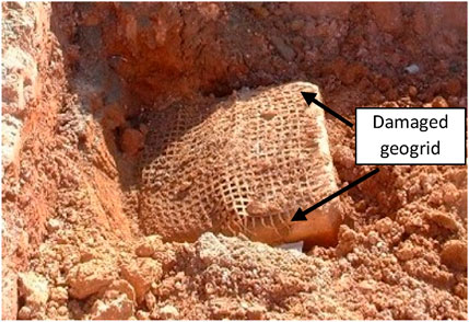
Figure 1. Geogrid reinforcement damage caused by direct contact with the pile cap (Palmeira et al., 2022).
3 Laboratory tests and numerical analysis
In the present study, laboratory tests were conducted at a scale of 1:5 to simulate a reinforced piled embankment under axisymmetric conditions (Figures 2A,B) in a controlled environment (Melchior Filho, 2022). The filling material consisted of a 0.45 m gravel layer over square caps measuring 0.2 m on each side, spaced 0.5 m apart (center to center). The instrumentation included: (i) five total pressure cells placed at various locations in the soil mass, (ii) a load cell positioned over the central pile, and (iii) four displacement transducers (Figure 2C).
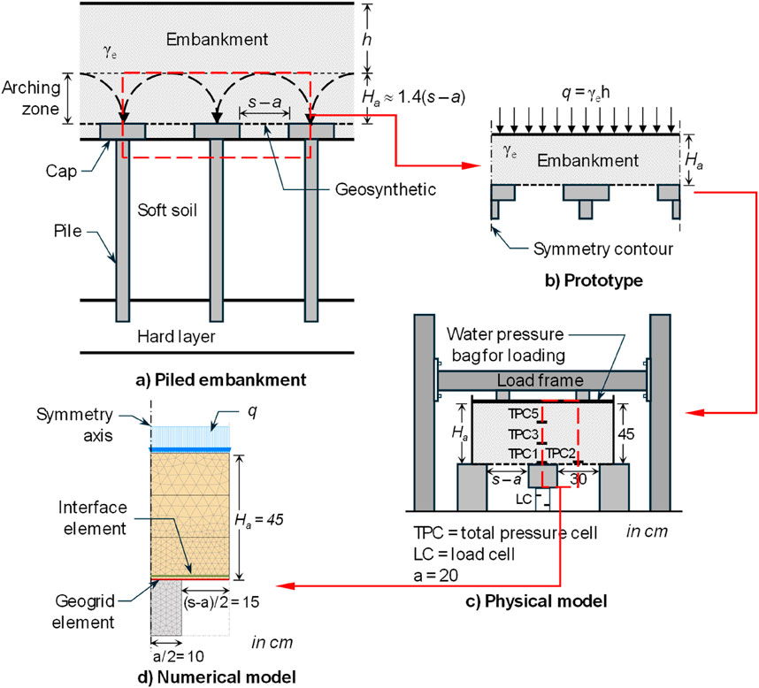
Figure 2. (a) Piled embankment, (b) Prototype, (c) Physical model and (d) Numerical model.
To better understand the stress distribution, numerical analyses were also performed alongside the laboratory tests, utilizing the geometry depicted in Figure 2D under axisymmetric conditions. These analyses were conducted using PLAXIS 2D Finite Element software (Brinkgreve and Vermeer, 2012). The medium was discretized using a mesh composed of 815 triangular elements, formed by 15 nodes and 12 stress points (Gauss integration points), each. In the soil-geogrid-pile contact, interface elements were incorporated, consisting of 5 pairs of nodes and 5 stress points. The soil behavior was modeled using the hardening soil model (Schanz et al., 1999), while the geosynthetic was represented by a geogrid-type element, consisting of 5 nodes and 5 stress points. This type of element only allows for the development of tension forces. Although the pile caps had a square cross-section, they were modeled as circular shapes using the equivalent area concept, as suggested by Han and Gabr (2002). The gravel properties were obtained from large direct shear tests, and the properly scaled tensile strength and stiffness of the geosynthetics were obtained through wide strip tensile tests (ASTM D6637, 2015), as summarized in Table 1.
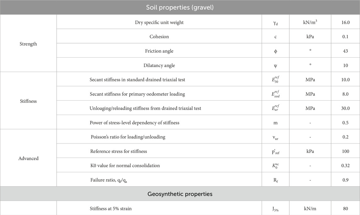
Table 1. Embankment and reinforcement properties for numerical analysis.
The embankment construction was simulated in three phases, each consisting of lifts of 0.15 m in height, followed by three surcharge applications of 10 kPa (phase 4), 25 kPa (phase 5), and 40 kPa (phase 6). For boundary conditions, the bottom of the geometry was fixed, while the vertical boundaries were allowed to move freely in that direction. Preliminary analyses were conducted to determine the maximum horizontal distance necessary to avoid boundary influences. Additionally, a mesh refinement analysis was performed (Cunha, 2025).
4 Results
Results were obtained from the physical model, including the variation of total pressure at different points within the embankment, measured by total pressure cells (TPC, Figure 1C), as well as the load applied at the central pile head (LC). Simultaneously, the numerical model calculated total pressures at integration points located at the same positions as those of the TPCs in the physical model, enabling a direct comparison between predicted and measured values.
Figures 3a,b present graphs showing the variation of vertical stress (σ) recorded at TPC-1 and TPC-2 cells, respectively, as a function of the dimensionless ratio between the embankment thickness (H) and the distance between caps (s-a). These results are shown for both models: physical (PM) and numerical (NM). The first graph (Figure 3a) represents the vertical stress acting on the pile cap, while the second (Figure 3B) corresponds to the vertical stress on the geogrid reinforcement. A vertical stress of up to 350 kPa on the pile cap for an H/(s-a) ratio of 10 was observed (Figure 3a). In contrast, the vertical stress on the geogrid is significantly lower, with maximum values around 12 kPa (Figure 3b), showing the effect of soil arching. Moreover, the numerical model accurately reproduces the behavior observed at TPC-1, showing only minor discrepancies for H/(s-a) values above 6. On the other hand, regarding the geogrid, although the numerical model results follow the same general trend as the physical model, notable differences in stress magnitudes exist. This discrepancy is attributed to limitations of the numerical model in simulating embankment soil arching and soil-reinforcement interaction and/or limitations of the total stress cell.
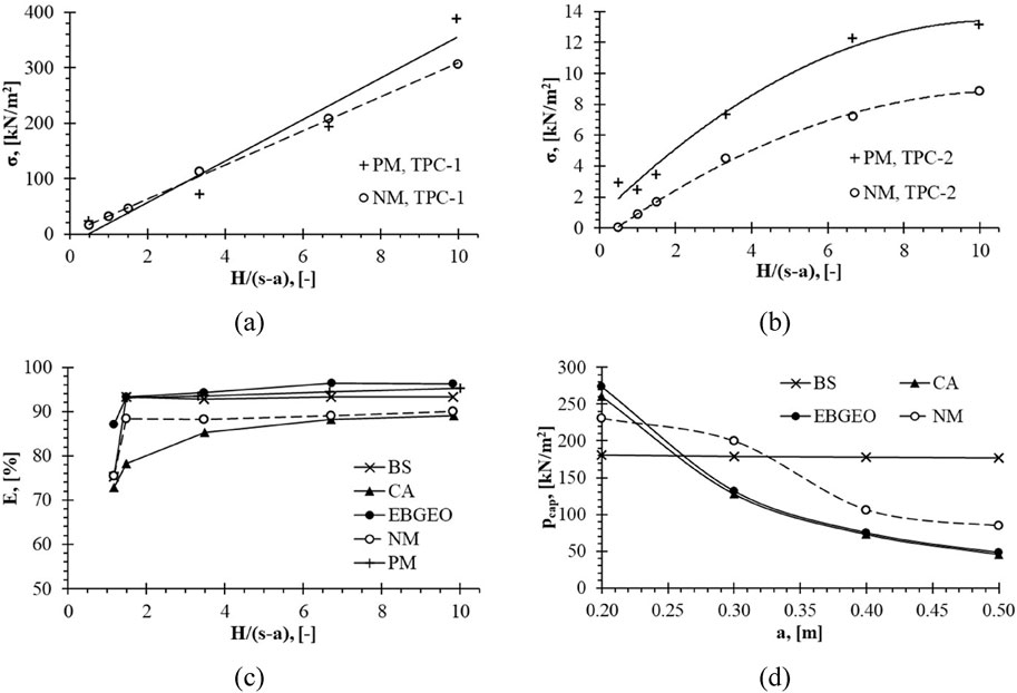
Figure 3. Obtained results: (a) σ recorded at TPC-1 versus H/(s-a), (b) σ recorded at TPC-2 versus H/(s-a), (c) Efficacy (E) versus H/(s-a) and (d) pcap versus a.
It is clearly observed that most of the embankment load is transferred directly to the pile head, with a system efficacy (E, defined as the ratio between the pile load and the embankment load on the pile tributary area) greater than 90% (Figure 3c). All the analyzed methods (British, German and Dutch methods) investigated in the present study showed similar predictions, with E values ranging between 85% and 95% for H/(s-a) ratios greater than 2. For values below 2, the arching phenomenon is not fully developed, which explains the differences among predictions by the methods, as each is based on distinct hypotheses and simplifications. The Dutch method (based on the concentric arches theory) compared best with the results from the numerical model.
With the successful validation of vertical stress magnitude at the pile cap in the numerical model, parametric analyses were conducted to evaluate the vertical stress on the pile cap (pcap) for different cap diameters (a). These results were compared with predictions from the British (BS), German (EBGEO), and Dutch (CA) methods, and the results are presented in Figure 3d. Satisfactory agreement is observed both in trend and magnitude between the numerical model and the Dutch and German methods for values of a of 0.2 m and greater than 0.4 m. Larger deviations between predictions can be observed for the British method (BS), which maintained a practically constant pcap value regardless of the cap size.
5 Conclusion
In this paper, the predictions from three design methods for piled embankments were compared to results from laboratory and finite element analysis. Based on the results obtained, the following conclusions can be drawn:
• H/(s-a) ratios directly influence the arching effect and the stress on the reinforcement, as well as the agreement between predicted and measured values. Additionally, larger discrepancies between predictions and measurements were observed for the vertical stresses on the reinforcement layer.
• Regarding the stress on the pile cap, the numerical model predictions compared well with laboratory results and, in general, satisfactorily with the Dutch and German methods. In contrast, the British Standard (BS) method showed values that remained practically constant regardless of pile geometry.
• System efficacy was consistently high for embankment thickness-to-pile spacing ratios above 2, emphasizing the importance of the arching effect in load distribution.
• The validation of design methods under laboratory and numerical conditions highlights the importance of considering the interaction between system components in real-world projects, suggesting that future investigations should explore the influence of different soil types and environmental conditions on the performance of reinforced piled embankments.
Author contributions
JR: Methodology, Writing – original draft, Writing – review and editing. EP: Formal Analysis, Methodology, Validation, Writing – review and editing. GA: Formal Analysis, Validation, Writing – review and editing. JC: Methodology, Writing – review and editing. JF: Data curation, Writing – review and editing.
Funding
The author(s) declare that no financial support was received for the research and/or publication of this article.
Acknowledgments
The authors acknowledge the University of Brasília, the Coordination for the Improvement of Higher Education Personnel (CAPES), the National Council for Scientific and Technological Development (CNPq) and the Federal District Research Support Agency (FAP/DF) for their support to this research.
Conflict of interest
The authors declare that the research was conducted in the absence of any commercial or financial relationships that could be construed as a potential conflict of interest.
Generative AI statement
The author(s) declare that Generative AI was used in the creation of this manuscript. The AI tool was used for reviewing the English.
Any alternative text (alt text) provided alongside figures in this article has been generated by Frontiers with the support of artificial intelligence and reasonable efforts have been made to ensure accuracy, including review by the authors wherever possible. If you identify any issues, please contact us.
Publisher’s note
All claims expressed in this article are solely those of the authors and do not necessarily represent those of their affiliated organizations, or those of the publisher, the editors and the reviewers. Any product that may be evaluated in this article, or claim that may be made by its manufacturer, is not guaranteed or endorsed by the publisher.
References
Agarwal, E., Luo, N., and Liu, K. (2025). Probabilistic analyses of geosynthetic-reinforced pile-supported embankments using design methods and 3D finite element models considering soil variability. Geotext. Geomembranes 53 (2), 559–576. doi:10.1016/j.geotexmem.2024.12.002
ASTM D6637 (2015). Standard test method for determining tensile properties of geogrids by the single or multi-rib tensile method. West Conshohocken, PA: ASTM International.
Brinkgreve, R. B. J., and Vermeer, P. A. (2012). PLAXIS: finite element code for Soil and rock analyses, version 8. Rotterdam, Netherlands: Balkema.
BSI BS 8006 (2010). Code of practice for strengthened/reinforced soils and other fills. United Kingdom: British Standards Institution.
Chen, R.-p., Wu, K., Meng, F.-y., Wang, H.-L., and Cheng, H.-Z. (2024). Centrifuge modeling of downward soil arching below excavation base in dry sand. J. Geotechnical Geoenvironmental Eng. 150 (9), 04024081. doi:10.1061/jggefk.gteng-12041
Cunha, J. A. (2025). “Numerical analysis to comprehend piled reinforced embankments behaviour,” in Master’s degree dissertation, publication G.DM-418/2025. Brasília, DF: Department of Civil and Environmental Engineering, University of Brasilia, 97. (In Portuguese).
CUR 226 (2016). in Design guideline basal reinforced piled embankments. Editors S. J. M. van Eekelen, and M. H. A. Brugman (Delft: SBRCURnet and CRC press).
EBGEO (2011). Recommendations for design and analysis of Earth structures using geosynthetic reinforcements -EBGEO. Germany: EBGEO.
Filz, G. M., and Smith, M. E. (2006). Design of bridging layers in geosynthetic-reinforced, column-supported embankments. Charlottesville, VA, USA: Virginia Transportation Research Council, 46p.
Fonseca, E. C. A., and Palmeira, E. M. (2019). Evaluation of the accuracy of design methods for geosyntheticreinforced piled embankments. Can. Geotechnical J. 56, 761–773. doi:10.1139/cgj-2018-0071
Girout, R., Blanc, M., Thorel, L., Fagundes, D., and Almeida, M. S. S. (2016). Arching and deformation in a piled embankment: Centrifuge tests compared to analytical calculations. J. Geotechnical Geoenviromental Eng. 142 (12), 04016069. doi:10.1061/(asce)gt.1943-5606.0001557
Guo, W., Wang, X., He, C., Jiang, L., Long, Y., Guo, Z., et al. (2023). Seismic performance of near-fault geosynthetic-reinforced pile-supported embankment. Geosynth. Int. 30 (5), 469–479. doi:10.1680/jgein.21.00105
Han, J., and Gabr, M. A. (2002). Numerical analysis of geosynthetic-reinforced and pile-supported Earth platforms over soft soil. J. Geotechnical Geoenvironmental Eng. 128 (1), 44–53. doi:10.1061/(asce)1090-0241(2002)128:1(44)
Heitz, C. (2006). Bodengewölbe unter ruhender und nichtruhender belastung bei berücksichtigung von bewehrungseinlagen aus geogittern, 19. Germany: Schriftenreihe Geotechnik, Uni Kassel.
Hewlett, W. J., and Randolph, M. A. (1988). Analysis of piled embankments. Ground Eng. April., 12–18.
Hosseinpour, I., Almeida, M. S. S., and Riccio, M. (2015). Full-scale load test and finite-element analysis of soft ground improved by geotextile-encased granular columns. Geosynth. Int. 22 (6), 428–438. doi:10.1680/jgein.15.00023
Kadhima, S. T., Parsonsc, R. L., and Han, J. (2018). Three-dimensional numerical analysis of individual geotextile-encased sand columns with surrounding loose sand. Geotext. Geomembranes 46 (2), 836–847. doi:10.1016/j.geotexmem.2018.08.002
Liu, H., Luo, Q., El Naggar, M. H., Liu, K., and Wang, T. (2024). Evaluating stability of rigid-column-supported and geosynthetic-reinforced embankments. Geosynth. Int. 31 (5), 711–727. doi:10.1680/jgein.23.00070
Liu, S., Yu, H., Zhao, C., Bian, X., and Chen, Y. (2025). Evolution of soil arching in geosynthetic-reinforced pile-supported embankment of a high-speed railway under long-term train traffic loading and excessive subsoil settlement. J. Geotechnial Geoenvironmental Eng. 151 (5), 04025028. doi:10.1061/jggefk.gteng-12497
Melchior Filho, J. (2022). Soil-geosynthetic interaction of piled embankment using large scale experiments. PhD thesis. Brasilia, DF: Department of Civil and Environmental Engineering. University of Brasilia, 121.
Nguyen, V. D., Luo, Q., Wang, T., Liu, K., Zhang, L. T. P., and Nguyen, T. P. (2023). Load transfer in geosynthetic-reinforced piled embankments with a triangular arrangement of piles. J. Geotechnical Geoenvironmental Eng. 149 (2), 04022131. doi:10.1061/jggefk.gteng-10586
Palmeira, E. M., Melchior Filho, J., and Fonseca, E. C. A. (2022). An evaluation of reinforcement mechanical damages in geosynthetic reinforced piled embankments. Soils and Rocks 45 (3), 1–15. doi:10.28927/SR.2022.000522
Pham, M.-T., Briaçon, L., Dias, D., and Abdelouhab, A. (2018). Investigation of load transfer mechanisms in granular platforms reinforced by geosynthetics above cavities. Geotext. Geomembranes 46 (5), 611–624. doi:10.1016/j.geotexmem.2018.04.015
Riccio, F. M. V., Bastos, F. S., Almeida, M. S. S., Fagundes, D. F., Rigolon, J. M., and Avila, C. B. (2024). Numerical analysis of a monitored piled-supported embankment of an airport runway. Transp. Geotech. 44, 101157. doi:10.1016/j.trgeo.2023.101157
Rui, R., Ding, R.-h., Han, J., Ye, Y.-q., He, S.-K., and Elabd, M. (2024). Evaluating ground reaction curves from single to multiple trapdoor tests. J. Geotechnical Geoenvironmental Eng. 150 (7), 04024054. doi:10.1061/jggefk.gteng-12187
Schanz, T., Vermeer, P. A., and Bonnier, B. G. (1999). “The hardening soil model: formulation and verification,” in Beyond 2000 in computational geotechnics - 10 years of PLAXIS. United Kingdom: Taylor & Francis, 16.
Van Eekelen, S. J. M. (2015). Basal reinforced piled embankments. Delft, Netherlands: PhD. Thesis, Technical University of Delft.
van Eekelen, S. J. M., Bezuijen, A., and van Tol, A. F. (2011). Analysis and modification of the british standard BS8006 for the design of piled embankments. Geotext. Geomembranes 29, 345–359. doi:10.1016/j.geotexmem.2011.02.001
Van Eekelen, S. J. M., Bezuijen, A., and van Tol, A. F. (2013). An analytical model for arching in piled embankments. Geotext. Geomembranes 39, 78–102. doi:10.1016/j.geotexmem.2013.07.005
van Eekelen, S. J. M., Bezuijen, A., and van Tol, A. F. (2015). Validation of analytical models for the design of basal reinforced piled embankments. Geotext. Geomembranes 43, 56–81. doi:10.1016/j.geotexmem.2014.10.002
Wang, T., Nguyen, V. C., Bui, P. D., Luo, Q., Liu, K., and Zhang, L. (2023). Three-dimensional physical modeling of load transfer in basal reinforced embankments under differential settlement. Geotext. Geomembranes 51 (2), 330–341. doi:10.1016/j.geotexmem.2022.12.001
Keywords: reinforced piled embankments, geosynthetics, laboratory tests, numerical analysis, instrumentation
Citation: Rebolledo JFR, Palmeira EM, Araújo GLS, Cunha JAd and Filho JM (2025) Evaluation of the accuracy of three design methods for reinforced piled embankments. Front. Built Environ. 11:1702362. doi: 10.3389/fbuil.2025.1702362
Received: 09 September 2025; Accepted: 17 October 2025;
Published: 03 November 2025.
Edited by:
Mario Riccio, Juiz de Fora Federal University, BrazilReviewed by:
Bruno Lima, Rio de Janeiro State Federal University, BrazilCopyright © 2025 Rebolledo, Palmeira, Araújo, Cunha and Filho. This is an open-access article distributed under the terms of the Creative Commons Attribution License (CC BY). The use, distribution or reproduction in other forums is permitted, provided the original author(s) and the copyright owner(s) are credited and that the original publication in this journal is cited, in accordance with accepted academic practice. No use, distribution or reproduction is permitted which does not comply with these terms.
*Correspondence: Gregório Luís Silva Araújo, Z3JlZ29yaW9AdW5iLmJy