 Ji Li
Ji Li Fan Yang2
- 1Electronic Information and Electrical Engineering College, Shangluo University, Shangluo, China
- 2Shanghai Sunshine Power Supply Co. Ltd, Shanghai, China
Virtual synchronous generator (VSG) control technology for photovoltaic, energy storage, wind power, and other new energy to provide flexibility in the grid interface characteristics, is conducive to improving the stability of the power system, and has been widely considered by many scholars. Firstly, an improved VSG control method is proposed through simulation and analysis, which realizes the complete decoupling of the frequency response time constant and the inertia quantity of the active power control loop and reduces the complexity of the parameter design of the VSG system. Secondly, to avoid the frequent action of the VSG system caused by small-scale frequency change perturbation, this study proposes a VSG frequency optimization control method for VSG frequency control with rated angular velocity ωset feedforward composed of multivariate factors when considering a primary frequency regulation dead zone. Thirdly, the impact of VSG parameter design on the system is investigated through the system response characteristics of power scheduling, primary frequency regulation at the grid connection, and the small-signal dynamic characterization of the improved VSG. Finally, Simulation and experimental verification yielded an active power overshoot of 7% and a maximum frequency deviation of 0.17 Hz for the improved system. The improved control method resulted in an improvement of 0.1 s in the frequency response time and a reduction of 0.15 Hz in the oscillation amplitude. The response speed of the improved control method is much better, while the oscillation amplitude is reduced to meet the grid's regulation requirements. The simulation and experimental analysis verify the feasibility of the improved VSG control method.
1 Introduction
The output power of renewable energy generation systems such as solar and wind power, which are interfaced with grid-connected inverters, is characterized by intermittency and uncertainty. More and more new energy devices are connected to the power grid, which seriously affects the stable operation of the power system (Rocabert et al., 2012; Liu et al., 2015; Shuai et al., 2018). In addition, most distributed generation (DG) in the microgrid is employed through the power electronic interface, and the penetration rate of DG has been steadily increasing in recent years (Zaitsev et al., 2022; Zhong and Weiss, 2011). Synchronous inverters, virtual synchronizers, and improved sag control have been mentioned more often (Djouadi et al., 2023; Mo et al., 2017; Meng et al., 2019; Belkhier et al., 2022). Virtual synchronous generator (VSG) technology emulates the rotor inertia and damping characteristics of synchronous generators, presenting friendly characteristics to a power grid and improving a system's stability (Liu et al., 2017; Lü et al., 2014). In recent years, the VSG control technique has received the attention of many scholars.
With more and more scholars focusing on VSGs, many researchers have proposed different VSG control architectures to improve the system's performance. Furthermore, in order to improve the transient stability of the system, some scholars have adopted adaptive control strategies (Pan et al., 2020; Xiong et al., 2021a; Wu and Wang, 2020), mode-switching (Shen et al., 2023), the virtual negative resistance method (Zhang et al., 2016), and the virtual inductor method (Guerrero et al., 2005; Wen et al., 2020), among others. Yu et al. (2024) and Othman et al. (2020) proposed optimal virtual inertia and damping ratio control methods for VSGs using parameter optimization, which eliminated the system's low-frequency oscillations and improved the frequency droop and frequency rate of change. Optimizing the design of VSG parameters is also often adopted by scholars, such as co-designing control parameters (Singh et al., 2023; Qu et al., 2020; Jain et al., 2024) and modifying the power reference (Li and Kao, 2009; Xiong et al., 2021b; Chen et al., 2022; Kirkland et al., 2022; Pan et al., 2019). In addition, improved voltage and current loops are often applied, such as the voltage drop method used by Wang and Wai (2019) and the current compensation method used by Li et al. (2016) and Wang and Wai (2022). These studies contribute to full power decoupling and have strong robustness but have the disadvantages of being applied under certain conditions and increasing the complexity of the algorithms. In considering the influence of the primary frequency dead zone on the VSG characteristics, An et al. (2019) propose a feedforward control and adopt the main frequency modulation coefficient correction strategy used by An et al. (2019) and Kirkland et al. (2022). These methods can be summarized as shown in Table 1 (Wang and Wai, 2022). Although many improved VSG control methods have been proposed recently, the contradiction between improving the system performance and simplifying the parameter design has yet to be resolved.
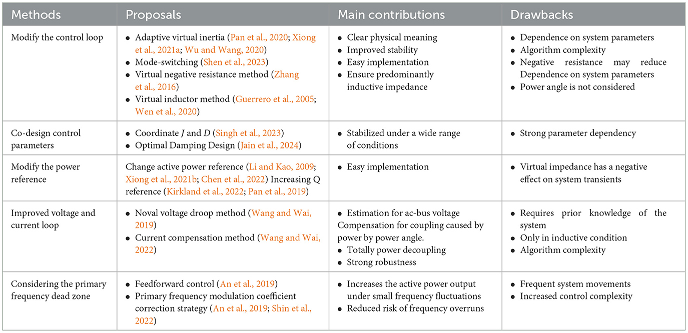
Table 1. Existing performance improvement methods for VSG.
This study focuses on improving VSG systems' performance and weakening the parameters' effects on the system's response. The major contributions of this article are summarized as follows:
1) An improved VSG control method is proposed to realize the complete decoupling of the frequency response time constant and inertia of the active power control loop and reduce the complexity of VSG system parameter design.
2) Considering the primary frequency dead zone and power-limiting device based on a multivariate factor consisting of rated angular velocity ωset feedforward is proposed as an optimal control method for VSG frequency tuning to avoid the frequent action of the VSG system caused by the small range of frequency perturbation.
3) By analyzing the system's response characteristics of power scheduling and primary frequency modulation at the grid connection and the small-signal dynamic characteristics of the improved VSG, the influence of the VSG parameter design on the impact on the system is investigated, which provides ideas for the parameter design.
The rest of this article is organized as follows: The VSG model is established and the basic principle of the VSG is analyzed in Section II. In Section III, an improved VSG control method is proposed by analyzing the influence of VSG parameters on the system. The VSG control strategy is further optimized based on primary frequency regulation dead zone considerations. In Section IV, the small-signal dynamic characteristics of the improved VSG are analyzed by the VSG parameters' design. In Section V, the simulation model and experimental platform are built to verify the rationality and effectiveness of the theoretical analysis. Section VI presents our conclusions.
2 Theoretical analysis
Diode-clamped three-level inverters are commonly utilized in grid-connected solar and energy storage converters because of their straightforward design and controllability. The “I”-type three-level topology is used in the main circuit of the VSG energy storage converter in this work, as seen in Figure 1 (Zhang et al., 2019). Through an inductor and capacitor (LC) filter, the VSG is directly linked to the grid, and the DC side of the inverter is a lithium energy storage battery, which, during steady-state operation, may be roughly described as a stable DC power supply. The battery can be charged or discharged using one of the two functioning modes of the energy storage converter; the discharging mode is the primary subject of this study. The filter inductor and capacitor in the converter are denoted by L and C, respectively, while Udc is the corresponding DC power supply. Lg is the grid-side line inductance, Ug is the grid voltage, and Uabc and Iabc are the three-phase output voltage and output current of the VSG's main circuit. The closed voltage–current loop, the pre-synchronization control unit, the power-frequency regulator, the excitation regulator, and the stator electrical equation make up the majority of the VSG control block diagram.
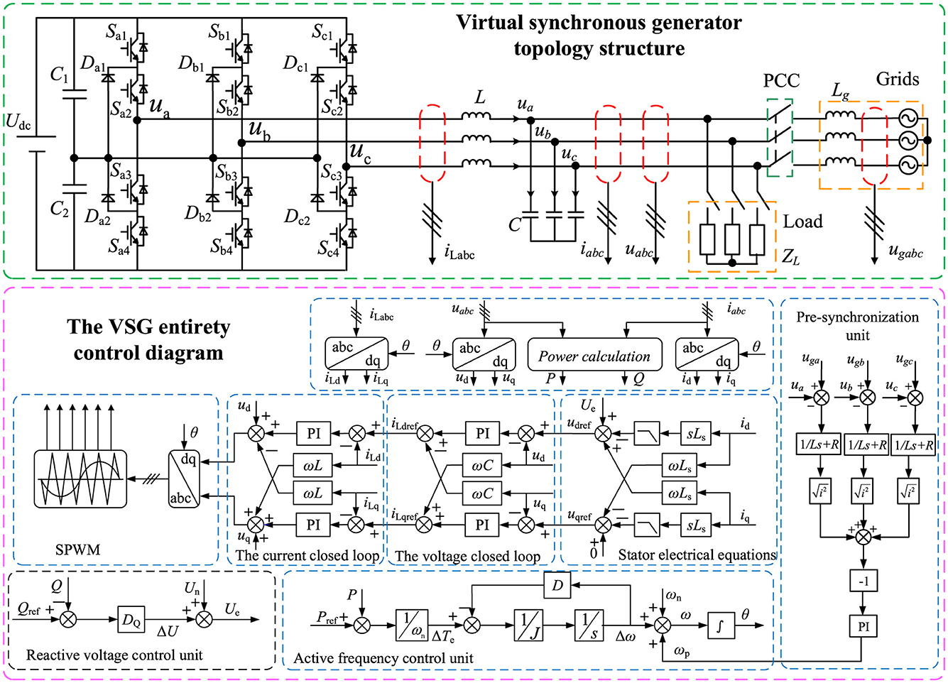
Figure 1. Topology and control diagram of the virtual synchronous generator (VSG; Zhang et al., 2019).
From the block diagram of the VSG control structure in Figure 1, it can be seen that the VSG control technique introduces the synchronous generator rotor equations of motion containing rotational inertia and damping coefficients into the inverter. The VSG control technique gives the inverter the characteristics of a synchronous generator operation and provides the system with virtual inertia to achieve frequency regulation (Belkhier et al., 2022; Liu et al., 2017). The rotor motion is expressed as
where J is the rotational inertia; ω and ωn are the rotor angular velocity and rated angular velocity, respectively; Tm and Te are the mechanical torque and electromagnetic torque; Pref is the reference value of active power setting; P is the actual output power; D is the damping coefficient; and δ is the power angle.
Simplifying Equation 1 gives
where τ1 = J/D, m1 = 1/Dωn.
Equation 2 shows that an inertia link is added to the active power and frequency transfer functions for droop control once the rotor equations of motion are incorporated into the control algorithm. The combination of the damping coefficient and rotational inertia determines the amount of system inertia. The damping coefficient is the single factor determining the droop coefficient; the more damping, the lower the frequency dip value.
The excitation regulation is added to the VSG reactive power control loop to imitate the reactive power voltage droop characteristics of the synchronous generator. The reactive power-voltage control expression is as follows:
where Qref is the supplied reactive power, Q is the reactive power, DQ is the reactive power voltage droop factor, and Un is the rated voltage magnitude.
Overall, the design idea for VSG control is to add frequency and voltage control loops to the synchronous generator model. After stabilizing the voltage and frequency, the rotor inertia is then simulated to improve the stable off-grid and on-grid operation of the inverter.
3 Analysis of the improved VSG control
3.1 Improved VSG principal analysis
From the previous section, it can be seen that the VSG control is droop control with rotor inertia. To simulate the synchronous generator characteristics more accurately, the prime mover regulation equation is added to the VSG power frequency control (Pan et al., 2019). Equation 1 is rewritten as
where Kω is the frequency regulation parameter.
Simplifying Equation 4 gives
where τ2 = Jωn/(Dωn + Kω), m2 = 1/(Dωn + Kω).
From Equation 5, it can be seen that the rotational inertia J, the damping coefficient D, and the frequency adjustment parameter Kω affect the frequency response stability and the dynamic adjustment time of the VSG system. When J is fixed, the roles of Kω and D are the same. Adjusting either the Kω or D parameter affects the time constant τ2 and the droop coefficient m2, which increases the complexity when designing the parameters of the VSG system. The VSG power-frequency regulation controller incorporating prime mover regulation is shown in Figure 2A. A droop characteristic exists between active power and frequency, and the VSG has the self-synchronization characteristic of a conventional generator. When the grid frequency rises (falls), the VSG automatically reduces (increases) the active power injected into the grid and participates in the primary frequency regulation of the power grid.
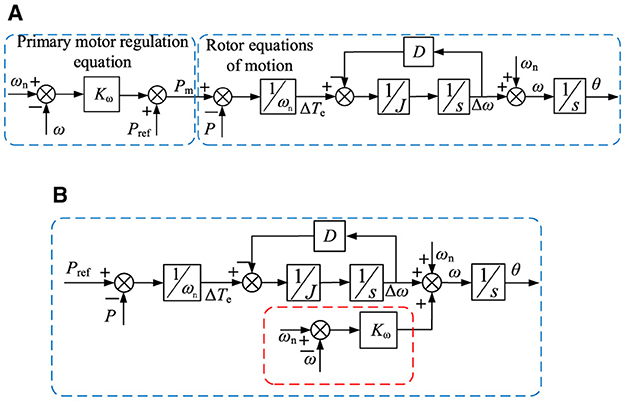
Figure 2. Virtual synchronous generator (VSG) power frequency regulation controller. (A) VSG with prime mover regulation. (B) Improved VSG.
Based on the preceding analysis, the improved VSG active frequency regulation controller acts as the virtual prime mover directly on the VSG output frequency based on the traditional VSG control. This improved control method skips the droop link of the rotor equation of motion, which cannot be realized this way by the real generator. The improved VSG power-frequency regulation controller is shown in Figure 2B. The improved active power-frequency control expression is as follows:
Simplifying Equation 6 gives
where τ3 = J/D, m3 = 1/(Dωn+Kω).
From Equation 7, it can be seen that the time constant τ3 is adjusted by parameter J and that the droop coefficient m3 is adjusted by Kω when the VSG system parameter D is fixed. The complete decoupling of the time constant τ3 and the droop coefficient m3 in the off-grid mode is realized when D is fixed. The improved VSG power-frequency regulation control can recognize that the static characteristics are regulated by J alone and the dynamic characteristics are regulated by Kω, which reduces the complexity of VSG system parameter design. Usually, D has a great influence on system stability in grid-connected mode (Mo et al., 2017; Meng et al., 2019), so the damping parameter D selected based on grid-connected mode can also be applied to off-grid mode.
The simulation model before and after the improved active power control loop is constructed as shown in Figure 2 to analyze the effect of circuit parameter changes on the VSG's frequency response. The frequency response curves under different parameters are shown in Figure 3. The VSG has a power increase of 10 kW at 0.3 s in off-grid operation mode. The frequency response metrics are shown in Table 2 when comparing curves 2, 3, and 4 in Figure 3. It can be seen that the improved control strategy in the parameter changes in the frequency can respond quickly. As can be seen from the comparison of curves 2 and 4 in Figure 3A with curve 1, respectively, both D and Kω affect the droop coefficient. Adjusting Kω has almost no effect on the frequency response, and the droop coefficient is mainly adjusted by D. Curves 2, 3, and 4, respectively, and curve 1 are compared; J, D, and Kω will have an effect on the frequency response time, and after adjusting the inertia time constant, J and D have a greater impact. As can be seen from the comparison of curves 2, 3, and 4 in Figure 3B with curve 1, respectively, both D and Kω have a large effect on the droop coefficient. Only J and D affect the regulation of the inertia time constant. In the parameter design of the improved VSG system, the parameter D can be fixed, the time constant τ3 can be adjusted through the parameter J, and the droop factor m3 can be adjusted through Kω. Comparing the frequency response curves analyzed before and after improving the active power control loop, the improved VSG system reduces the parameter design's complexity.
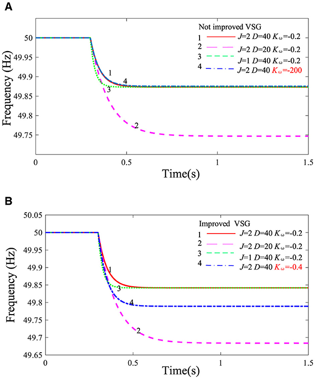
Figure 3. Virtual synchronous generator (VSG) frequency response curves with different parameters. (A) VSG without improved active power control loop. (B) VSG with improved active power control loop.
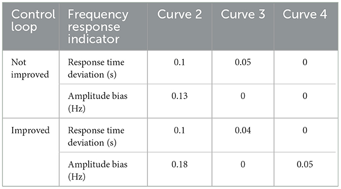
Table 2. Comparison of frequency response indexes of different control loops.
3.2 Optimization analysis of VSG control strategy considering the primary frequency regulation dead zone
From the analysis in the previous section, it can be seen that the VSG active power control loop is essentially a kind of droop control. When the VSG operates in a grid-connected operation, the rotational inertia J, the damping coefficient D, and the frequency regulation parameter Kω determine the VSG frequency modulation capability and the dynamic characteristics of the active power in grid-connected operation, that is, the amount of the increase (decrease) of the output active power of the VSG during the dip (rise) in the frequency of the power grid. When VSGs are operated in parallel, they can be equivalent to a controlled voltage source, and the equivalent circuit of multiple VSGs connected to the grid is shown in Figure 4.
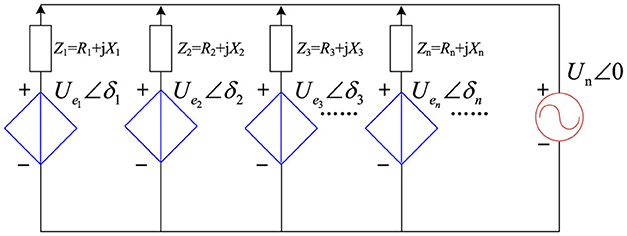
Figure 4. Equivalent circuit of a virtual synchronous generator connected to the grid.
Usually, the grid-side line impedance is predominantly inductive, and the power angle is usually small so that sinδ ≈ δ. The power interaction of each VSG with the grid can be expressed by Equation 8:
Combining Equations 6–8, the simplified control block diagram of the improved active power frequency control loop is obtained as shown in Figure 5.
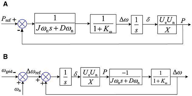
Figure 5. Improved virtual synchronous generator control block diagram. (A) Block diagram of the power scheduling control loop. (B) Block diagram of primary frequency regulation control loop.
From Figure 5B, it can be seen that the power response of the primary frequency regulation is only a part of the power frequency control loop, and the Δωref transformation inevitably induces a change in power. When the VSG system participates in the grid's primary frequency regulation, the frequency regulation dead zone is too small, which will lead to frequent operation of the VSG unit and reduce the equipment life. To avoid the VSG system action caused by small frequency perturbations, controlling Δωref to zero is necessary so that there is no power angle generation in the system. If the dead zone is too large, the VSG unit may still not participate in the frequency response when the frequency deviation is large, which affects the VSG's primary frequency regulation effect, then directly affects the system's frequency safety, and triggers the frequency overrun problem (Wang and Wai, 2019; Marton and Lantos, 2011).
In this work, the proposed frequency regulation dead zone and power-limit sub-setting method are shown in Figure 6. In the figure, Δω(t) is the angular frequency deviation of the system, and Pw(t) is the active power of the VSG system during primary frequency regulation. P0 is the initial active power output of the VSG, ωL is the frequency deviation corresponding to when the VSG reaches the maximum active power threshold, and d is the frequency dead zone. When the frequency deviation |Δω(t)| is less than or equal to the set frequency dead zone d, the VSG does not participate in the system's primary frequency regulation, and the output power remains fixed. When the frequency deviation |Δω(t)| is greater than or equal to the frequency deviation ωL corresponding to the maximum active power threshold, the VSG maintains a maximum active power threshold operation. When the frequency deviation |Δω(t)| is greater than d and less than ωL, the VSG unit participates in the system's primary frequency regulation. The active power-frequency droop control loop plays a role in realizing the dynamic support of the VSG's control of the grid frequency.
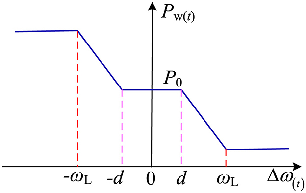
Figure 6. Frequency regulation characteristics of virtual synchronous generator considering the frequency regulation dead zone.
According to Figure 6, the primary frequency regulation power expression including the dead zone is shown in Equation 9:
where kvsg is the primary frequency regulation coefficient set when the VSG participates in grid frequency regulation.
According to Figure 6 and Equation 9, considering the VSG's frequency regulation characteristics in the dead zone of frequency regulation, an optimal control method of VSG frequency regulation with rated angular velocity ωset feedforward composed of multivariate factors is proposed. The VSG frequency response control model considering the primary frequency regulation dead zone is shown in Figure 7. From the real synchronous generator point of view, the VSG power angle is kept constant during small frequency perturbations to achieve constant VSG output power. Keeping the power constant only requires that Δωref be controlled to zero so that the power angle δ is zero. When a frequency fluctuation occurs in the VSG unit, the set value of ωset is selected in the power frequency control loop based on the frequency deviation. The setting value of ωset is based on the following three cases.
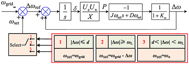
Figure 7. Virtual synchronous generator frequency response model considering the primary frequency regulation dead zone.
Case 1: When |Δω(t)| ≤ d, due to the transient nature of the grid frequency fluctuation and the delay of the grid frequency phase locking, as well as the presence of the damping link, ensuring that ωset = ωgrid is only necessary to realize Δω ≈ 0.
Case 2: When |Δω(t)|≥ωL, because the VSG is running at the active power maximum threshold steady state at this time, it has produced a certain power angle Δω ≠ 0. Therefore, only in the case of ωset = ωgrid – Δω, Δωref can be realized to be zero, and the power angle δ no longer changes so that the power is kept constant.
Case 3: When d < |Δω(t)| < ωL, the VSG operates in the primary frequency regulation stage so that ωset = ωn. This stage can generate a second-order system step response with the value of Δωref according to the difference between the grid frequency ωgrid and the rated frequency ωn in real time, realizing the dynamic active support to the grid.
4 Improved VSG static stability analysis
4.1 VSG parameter design
When the system operates in off-grid mode, the improved power-frequency control loop can be equivalent to a first-order system, realizing the complete decoupling of the time constant τ3 and the sag factor m3. In the grid-connected mode, the system has two main operating states, power scheduling and primary frequency regulation, and the power-frequency control loops can all be equated to a second-order system. The active power and frequency closed-loop transfer function expressions can be derived from the improved power-frequency control loop block diagram of Figure 5:
The undamped natural oscillatory angular frequency ω* and damping ratio ζ* are obtained for the active power and frequency second-order system:
where C = (Un Ue)/X.
From Equations 10, 11, it can be seen that the power scheduling and primary frequency regulation are both second-order systems, and the power scheduling and primary frequency regulation transfer functions have the same damping ratio and the same oscillation angular frequency, which present the same dynamic characteristics to the outside world. Due to the positive feedback relationship, the primary frequency regulation behaves as a negative response to the amount of frequency change. The active power dynamic characteristics of VSG in grid-connected mode are jointly determined by D, J, and Kω. To stabilize the system and, at the same time, require the system to have a good transient response characteristic curve, the second-order system operates in an underdamped state (0 < ζ* < 1). The system obtains the regulation time ts and the overshooting amount σ with a ±5% allowable error.
From Equations 12, 13, when the damping coefficient D and the frequency adjustment parameter Kω are fixed, the smaller J, the larger ζ*, and ts is longer. When J and Kω are fixed, D is larger, ζ* is smaller, and ts is shorter. It can be seen that as J increases, the system oscillation is more violent and less stable. As D increases, the system's response is smoother and can reach the steady state faster.
VSG parameter design can enhance system stability and improve system response time. In this paper, during the parameter design process, the rotational inertia refers to the VSG design method used by Katholieke Universiteit Leuven (Guerrero et al., 2005), so . The frequency adjustment parameter reference is (Zhong and Weiss, 2011). For a faster response time and less overshoot, ζ* can be set to the optimum damping ratio. Let ζ* = 0.707, the damping coefficient D be obtained:
On one hand, the VSG parameter design process focuses on the influence of the parameters on the power and frequency response of the system. On the other hand, comprehensively considering the system's requirements for transient response overshoot and overall damping is also necessary. According to the requirements of the system's operating conditions, the parameters are reasonably designed.
4.2 Small-signal dynamic characterization
When multiple VSGs are grid-connected, the circuit model of each VSG is the same. Drawing on the traditional synchronous generator single-machine infinite stability analysis method (Shen et al., 2023), a small-signal model is constructed according to Figure 5 to analyze the dynamic characteristics of the improved VSG system. During the VSG's steady-state operation, small-signal perturbations are processed at power angle δ, angular velocity ω, and output voltage Ue. Small-signal perturbation is also added to the active and reactive power, and the sampling filtering delay for power is replaced by a first-order low-pass filter. The VSG small-signal analysis model is obtained according to Equations 3, 6, 8:
where ωc is the filter cutoff frequency.
According to Equation 15, the following small-signal modeling characteristic equation is obtained:
where
Based on the improved VSG small-signal modeling, the results of the root trajectory stability analysis are shown in Figure 8. From Figures 8A, B, it can be seen that as the impedances R and L increase, two of the conjugate poles gradually move away from the imaginary axis and converge to the real axis, the system oscillation is weakened, and the stability is gradually enhanced. In Figure 8C, when the value of Kω is divided into two-end root trajectory trends, with −1 as the dividing line, the root will cross the longitudinal axis and appear in the positive half-plane only in the vicinity of −1, at which time the system is in an unstable state. In Figure 8D, with the process of increasing rotational inertia J, an integer root gradually nears the imaginary axis; at this time, the system stability gradually deteriorates. In Figure 8E, as the damping coefficient D gradually increases, all the poles move away from the imaginary axis, and the stability becomes better. In Figure 8F, as the reactive voltage sag coefficient Dq slowly increases, two of the conjugate eigen roots are also slowly moving closer to the imaginary axis, and the system oscillations increase and become unstable.
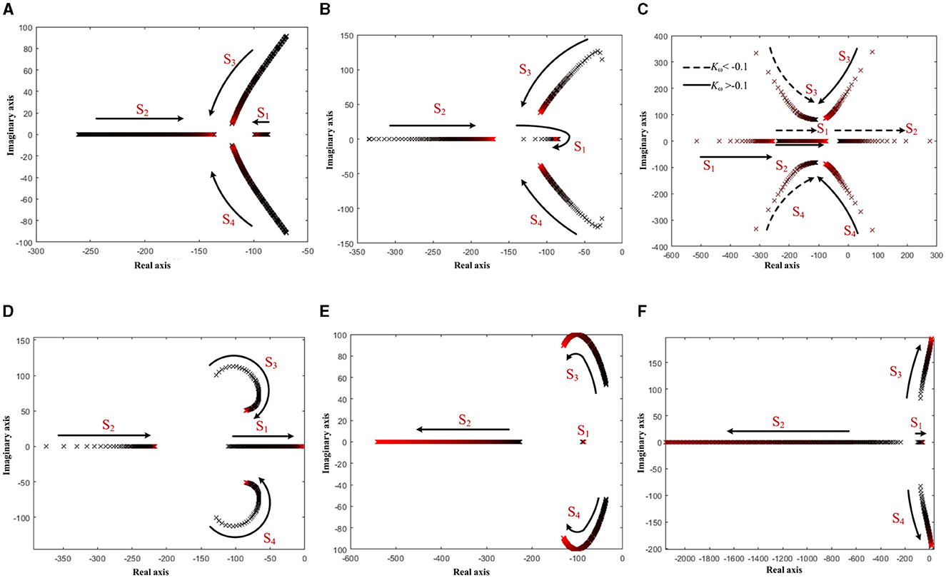
Figure 8. Poles and zeros of (A) R = 0.01–25, (B) L = 0.2–50 mh, (C) Kω = −2–1, (D) J = 0.005–5, (E) D = 0–50, and (F) Dq = 0.0001–0.05.
It can be seen that the VSG has the advantage of adjusting the system circuit parameter design according to the actual working conditions compared with the synchronous generator. In this section, the effect of the variation of each parameter of the VSG on the system, which provides a theoretical reference for the simulation and experimental parameter design, is analyzed.
5 Simulation and experimental analysis
To verify the effectiveness of the improved VSG control method, the simulation model shown in Figure 1 is built in this article using MATLAB/Simulink. The main circuit parameters of the simulation and experiment are shown in Table 3.
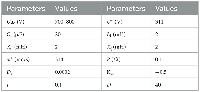
Table 3. The simulation model parameters.
5.1 Simulation validation
The primary frequency regulation and power scheduling response curve is shown in Figure 9. The VSG is connected to the grid at 0.2 s, and the blue curve is the power step response of changing the power scheduling value from 0 to 10 kW for the reference value of 10 kW given at 0.3 s. The red curve is the step response of the frequency change of the grid frequency from 50 to 49.5 Hz for the red curve at 0.3 s. Because the parameters of the system D, J, and Kω are kept the same, the active power dispatch response curve and the primary frequency response curve have the same trend, which is the second-order system unit step response under the same parameters.
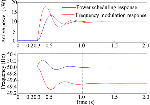
Figure 9. Primary frequency regulation and power scheduling response curves.
The active power and frequency response curves when varying the circuit parameters are shown in Figure 10. The VSG is connected to the grid at 0.2 s and the grid frequency drops from 50 to 49.5 Hz at 0.3 s. To realize the change of steady-state power, the unimproved VSG system adjusts the droop coefficient by adjusting the parameter D, while the improved VSG system adjusts the droop coefficient by adjusting the parameter Kω. The improved VSG system has much less effect on the transient oscillation process of the system by adjusting Kω than by adjusting D. It can be seen that the improved control method improves the frequency response time by 0.1 s and reduces the oscillation amplitude by 0.1 Hz. The improved VSG makes achieving the optimal control effect of the system easier through the parameter optimization design.
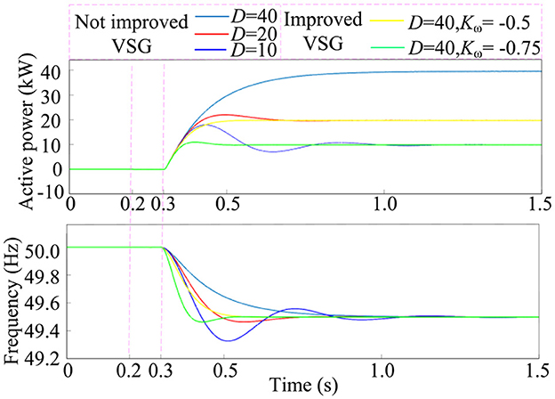
Figure 10. Primary frequency response with different parameters.
Through simulation analysis, the index comparison of this study with other control methods is shown in Table 4. The improved control method system has an active power overshoot of 7% and a maximum frequency deviation of 0.17 Hz. The proposed method in this article can recognize an active power overshoot and a smaller maximum deviation of frequency, better improving the output dynamic response characteristics.
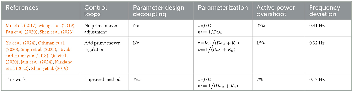
Table 4. Comparison with other methods.
The VSG frequency response curve considering the primary frequency regulation dead zone is shown in Figure 11. Considering the relationship between the droop coefficient and the Δω parameter, the maximum threshold of the VSG's frequency regulation power is set to 7.89 kW, and the frequency regulation dead zone is set to 0.1 Hz. The simulation model is set to close the grid-connecting switch at 0.2 s and drop the grid frequency from 50 to 49.9 Hz at 0.3 s. At 0.5 s, the grid frequency drops again to 49.8 Hz. At 1.5 s, the grid frequency drops further to 49.7 Hz, and at 2.5 s, the grid frequency returns to the rated 50 Hz. At 0.3 s, the grid frequency falls by 0.1 Hz, due to |Δω(t)| ≤ d, the frequency regulation being within the set dead zone, and the active power does not respond to not participate in a frequency regulation. At 0.5 s, the grid frequency continues to fall by 0.1 Hz, due to d < |Δω(t)| < ωL, as the frequency change has exceeded the regulation dead zone range, the VSG participates in frequency control; at this time, the active power output to the power-limit sub-value of 7.89 kW and remains stable. At 1.5 s, the grid frequency falls again by 0.1 Hz, and because |Δω(t)|≥ωL, the active power of the primary frequency regulation has reached the maximum limit value at this time; the VSG still maintains the maximum value of active power operation. At 2.5 s, the grid frequency returns to the rated 50 Hz, and the active power is also restored to the initial state of zero under the control of primary frequency regulation. The corresponding change in the relationship of power during the whole-grid frequency change process verifies the effectiveness of the frequency dead zone and power-limiting scheme proposed in this article. This method effectively guarantees the effect of the system's primary frequency regulation and avoids the frequent action of the VSG system caused by small-scale frequency disturbances.
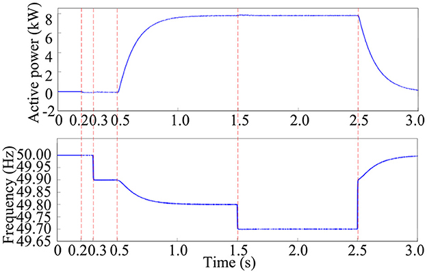
Figure 11. Primary frequency response of virtual synchronous generator considering the frequency regulation dead zone.
5.2 Experimental validation
To verify the correctness of the theoretical analysis, the VSG experimental platform built in this work is shown in Figure 12. A DC power source is used on the input side instead of the storage battery. The main circuit uses a 500 kW “I”-type three-level energy storage converter, and the controller uses a TMS320F28335 digital signal processing (DSP) control chip. The hardware and software parameters of the experimental platform are shown in Table 1. The active frequency droop factor m3 is converted to 100 kW/0.1 Hz.
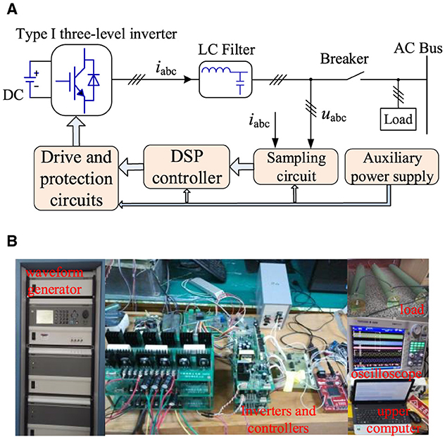
Figure 12. The virtual synchronous generator experiment platform. (A) The experimental schema. (B) Experimental device.
The experimental waveforms of the primary frequency regulation response are shown in Figure 13. Figure 13A shows the active power response waveform when the grid frequency drops from the rated value of 50 to 49.7 Hz in the grid-connected mode, and Figure 13B shows the active power response waveform when the frequency returns to the rated value. From Figure 13A, it can be seen that in the grid-connected condition, the grid frequency falls 0.3 Hz, and the system output active power is 300 kW stable operation. Figure 13B shows that the step recovery of the grid frequency occurs, the active power gradually decreases, and the VSG gradually returns to the no-load operation state.
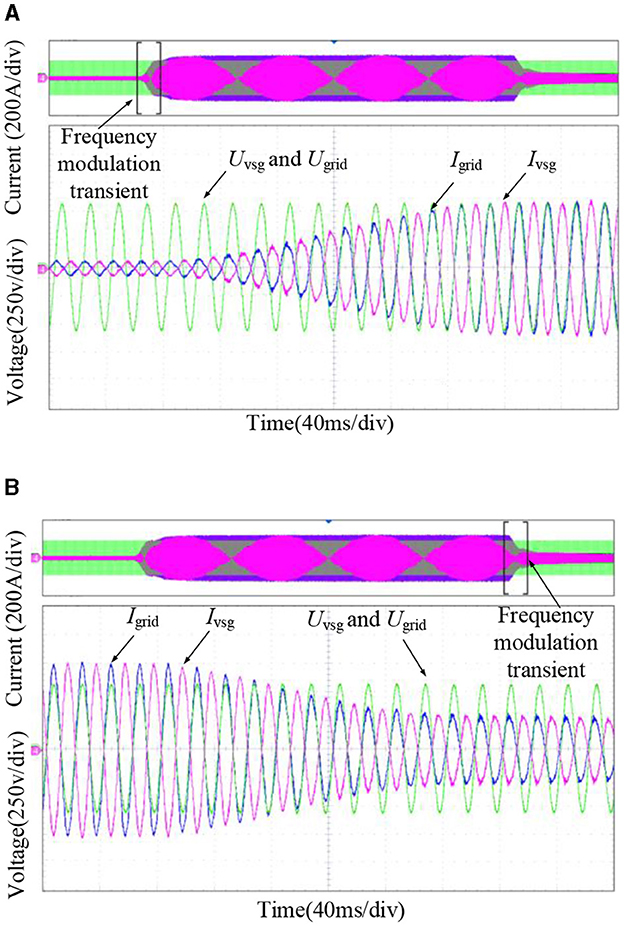
Figure 13. Experimental waveform of the primary frequency response. (A) Frequency-drop response curve. (B) Frequency recovery response curve.
The experimental waveform considering the primary frequency regulation dead zone is shown in Figure 14. The frequency regulation dead zone is set to 0.1 Hz, and the maximum power is 100 kW. In Figure 14A, when the frequency of the power grid fell from 50 to 49.9 Hz, the VSG was not involved in the grid-frequency adjustment due to the presence of a dead zone. The power fluctuation returns to the original value. Temporary power fluctuations are mainly caused by the delayed sampling of the VSG grid frequency. In Figure 14B, when the grid frequency drops from 50 to 49.8 Hz, the frequency disturbance deviation is greater than the set frequency dead zone, and the VSG participates in a frequency control to 100 kW-powered stable operation. When the frequency drops again, the system still runs at a maximum power limit of 100 kW. This experiment verifies the feasibility of the VSG control strategy optimization method when considering a dead zone.
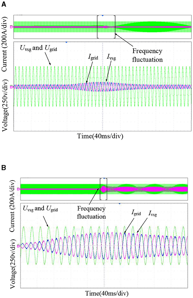
Figure 14. Experimental waveform considering the frequency regulation dead zone. (A) Response curve at |Δω(t)| ≤ d. (B) Response curve at |Δω(t)| ≥ ωL.
6 Conclusion
This article proposes an improved VSG control method for distributed power access microgrids that may cause frequency and power fluctuations in the grid. First, by building a virtual synchronous generator model, the mechanism of changes in system frequencies and output power in the interim process is analyzed. An improved VSG control method is proposed for the power-frequency control circuitry. Through theoretical and simulation analysis, the improved VSG system achieved the complete decoupling of the time constant and frequency adjustment parameters, reducing the complexity of parameter design. Second, to avoid the small-range frequency disturbance caused by the movement of the VSG system, based on considerations of a dead zone and a power limit, this article proposes a multivariable factor composed of quota angle speed ωset before feedback of the VSG frequencies optimization control method. This method effectively guarantees the system's primary frequency regulation effect, avoiding small-range interference, which causes frequent movement in the VSG system. Third, the preliminary VSG parameter design principles are given by analyzing the system response characteristics and the improved VSG small-signal dynamic characteristics during power scheduling and primary frequency regulation when connected to the grid. Finally, the VSG simulation model and experimental platform are constructed, and the simulation and experimental analyses verify the feasibility and effectiveness of the improved VSG control method. The improved control method system has an active power overshoot of 7% and a maximum frequency deviation of 0.17 Hz. The improved control method enhances the frequency response time by 0.1 s and reduces the oscillation amplitude by 0.15 Hz. The response speed of the improved control method is much better, while the oscillation amplitude is reduced to meet the grid's regulation requirements.
The research on the improved VSG control method in this article has certain theoretical guidance values for the parameter design and control strategy optimization in the engineering application of the VSG system. Under the existing hardware conditions, this study does not provide a validation analysis of the VSG fault ride-through capability and the improvement of transient immunity during load switching. Meanwhile, no experimental verification of parallel operation of multiple VSG systems has been carried out in this study. The next step is to verify the parallel operation of multiple VSG systems.
Data availability statement
The original contributions presented in the study are included in the article/supplementary material, further inquiries can be directed to the corresponding author.
Author contributions
JL: Conceptualization, Data curation, Formal analysis, Funding acquisition, Investigation, Methodology, Project administration, Resources, Software, Supervision, Validation, Visualization, Writing – original draft, Writing – review & editing. FY: Software, Writing – review & editing. HW: Data curation, Writing – review & editing. BC: Funding acquisition, Writing – review & editing.
Funding
The author(s) declare financial support was received for the research, authorship, and/or publication of this article. This work was supported by the Education Department Project of Shaanxi Province, China (20JK0611 and 23JK0427) and Shangluo University Research Program, China (20SKY016).
Conflict of interest
FY was employed by Shanghai Sunshine Power Supply Co. Ltd.
The remaining authors declare that the research was conducted in the absence of any commercial or financial relationships that could be construed as a potential conflict of interest.
Publisher's note
All claims expressed in this article are solely those of the authors and do not necessarily represent those of their affiliated organizations, or those of the publisher, the editors and the reviewers. Any product that may be evaluated in this article, or claim that may be made by its manufacturer, is not guaranteed or endorsed by the publisher.
References
An, H., Yang, J., Yang, W., Cheng, Y., and Peng, Y. (2019). An improved frequency dead zone with feed-forward control for hydropower units: performance evaluation of primary frequency control. Energies 12:1497. doi: 10.3390/en12081497
An, H., Yang, J., Yang, W., Cheng, Y., and Peng, Y. (2019). An improved frequency dead zone with feed-forward control for hydropower units: performance evaluation of primary frequency control. Energies 12:1497. doi: 10.3390/en12081497
Belkhier, Y., Achour, A., Bures, M., Ullah, N., Bajaj, M., Zawbaa, H. M., et al. (2022). Interconnection and damping assignment passivity-based non-linear observer control for efficiency maximization of permanent magnet synchronous motor. Energy Rep. 8, 1350–1361. doi: 10.1016/j.egyr.2021.12.057
Chen, M., Zhou, D., and Blaabjerg, F. (2022). Enhanced transient angle stability control of grid-forming converter based on the virtual synchronous generator. IEEE Trans. Ind. Electron. 69, 9133–9144. doi: 10.1109/TIE.2021.3114723
Djouadi, H., Ouari, K., Belkhier, Y., Lehouche, H., Ibaouene, C., Bajaj, M., et al. (2023). Non-linear multivariable permanent magnet synchronous machine control: a robust non-linear generalized predictive controller approach. IET Contr. Theory Appl. 17, 1688–1702. doi: 10.1049/cth2.12509
Guerrero, J. M., Garcia de Vicuna, L., Matas, J., Castilla, M., and Miret, J. (2005). Output impedance design of parallel-connected UPS inverters with wireless load-sharing control. IEEE Trans. Ind. Electron. 52, 1126–1135. doi: 10.1109/TIE.2005.851634
Jain, A., Pathak, M. K., and Padhy, N. P. (2024). Conjoint enhancement of VSG dynamic output responses by disturbance-oriented adaptive parameters. IEEE Trans. Industr. Informat. 20, 2079–2096. doi: 10.1109/TII.2023.3283540
Kirkland, S., Yao, W., Wen, J., and Jiang, L. (2022). A two-stage simultaneous control scheme for the transient angle stability of VSG considering current limitation and voltage support. IEEE Trans. Power Syst. 37, 2137–2150. doi: 10.1109/TPWRS.2021.3121474
Li, Y. W., and Kao, C. (2009). An accurate power control strategy for power electronics-interfaced distributed generation units operating in a low voltage multi bus microgrid. IEEE Trans. Power Electron. 24, 2977–2988. doi: 10.1109/TPEL.2009.2022828
Lietal, M. (2016). A novel virtual synchronous generator control strategy based on improved swing equation emulating and power decoupling method. Proc. IEEE Energy Convers. Congress Expo. Conf. 2016, 1–7. doi: 10.1109/ECCE.2016.7854751
Liu, J., Miura, Y., and Ise, T. (2015). Comparison of dynamic characteristics between virtual synchronous generator and droop control in inverter-based distributed generators. IEEE Trans. Power Electron. 31, 3600–3611. doi: 10.1109/TPEL.2015.2465852
Liu, J., Miura, Y., and Ise, T. (2017). Enhanced virtual synchronous generator control for parallel inverters in microgrids. IEEE Trans. Smart Grid 8, 2268–2277. doi: 10.1109/TSG.2016.2521405
Lü, Z., Sheng, W., Zhong, Q., Liu, H., Zeng, Z., Yang, L., et al. (2014). Virtual synchronous generator and its applications in micro-grid. Proc. CSEE 34, 2591–2603. doi: 10.13334/j.0258-8013.pcsee.2014.16.009
Marton, L., and Lantos, B. (2011). Control of robotic systems with unknown friction and payload. IEEE Trans. Control Syst. Technol. 19, 1534–1539. doi: 10.1109/TCST.2010.2086458
Meng, X., Liu, J., and Liu, Z. (2019). A generalized droop control for grid supporting inverter based on a comparison between traditional droop control and virtual synchronous generator control. IEEE Trans. Power Electron. 34, 5416–5438. doi: 10.1109/TPEL.2018.2868722
Mo, O., D'Arco, S., and Suul, J. A. (2017). Evaluation of virtual synchronous machines with dynamic or quasi-stationary machine models. IEEE Trans. Ind. Electron. 64, 5952–5962. doi: 10.1109/TIE.2016.2638810
Othman, M. H., Mokhlis, H., Mubin, M., Talpur, S., Aziz, N. F. A., Dradi, M., et al. (2020). Progress in control and coordination of energy storage system-based VSG. IET Renew. Power Generat. 14, 177–187. doi: 10.1049/iet-rpg.2019.0274
Pan, D., Liu, F., Wang, X., and Shi, R. (2020). Transient stability of voltage-source converters with grid-forming control: a design-oriented study. IEEE J. Emerg. Sel. Topics Power Electron. 8, 1019–1033. doi: 10.1109/JESTPE.2019.2946310
Pan, D., Wang, X., Liu, F., and Shi, R. (2019). Transient stability impact of reactive power control on grid-connected converters. Proc. IEEE Energy Convers. Congr. Expo. 2019, 4311–4316. doi: 10.1109/ECCE.2019.8912567
Qu, Z., Yang, H., Han, J., Song, C., Li, W., and Cai, Y. (2020). Effects analysis of excitation circuit on power control for VSG: a design-oriented study. IET Renew. Power Generat. 14, 803–810. doi: 10.1049/iet-rpg.2019.0389
Rocabert, J., Luna, A., Blaabjerg, F., and Rodriguez, P. (2012). Control of power converters in AC microgrids. IEEE Trans. Power Electron. 27, 4734–4749. doi: 10.1109/TPEL.2012.2199334
Shen, C., Gu, W., Sheng, W., and Liu, K. (2023). Transient stability analysis and design of VSGs with different DC-link voltage controllers. CSEE J. Power Energy Syst. 10, 593–604. doi: 10.17775/CSEEJPES.2022.03300
Shin, K., Li, W., Li, Z., Zeng, H., and Cheng, W. (2022). High-ratio wind power system unit combinations take into account the dead zone and limit of primary frequency regulation. Grid Technol. 46, 1326–1334. doi: 10.3390/en17081805
Shuai, Z., Shen, C., Liu, X., Li, Z., and Shen, Z. J. (2018). Transient angle stability of virtual synchronous generators using Lyapunov's direct method. IEEE Trans. Smart Grid 10, 4648–4661. doi: 10.1109/TSG.2018.2866122
Singh, V. K., Padhy, N. P., and Hote, Y. V. (2023). “Advanced control framework for stable operation of parallel connected microgrid inverters,” in 2023 IEEE International Conference on Power Electronics, Smart Grid, and Renewable Energy (PESGRE), Trivandrum, India, 1–6. doi: 10.1109/PESGRE58662.2023.10404773
Tayab, U. B., and Humayun, Q. M. (2018). Enhanced droop controller for operating parallel-connected distributed-generation inverters in a microgrid. J. Renew. Sustain. Energy 10. doi: 10.1063/1.5016422
Wang, Y., and Wai, R. J. (2019). Adaptive power decoupling strategy for single-phase grid-connected converter. IEEE Trans. Ind. Appl. 55, 4275–4285. doi: 10.1109/TIA.2019.2908945
Wang, Y., and Wai, R. J. (2022). Adaptive fuzzy-neural-network power decoupling strategy for virtual synchronous generator in micro-grid. IEEE Trans. Power Electron. 2022, 37–34. doi: 10.1109/TPEL.2021.3120519
Wen, T., Zou, X., Zhu, D., Guo, X., Peng, L., and Kang, Y. (2020). Comprehensive perspective on virtual inductor for improved power decoupling of virtual synchronous generator control. IET Renew. Power Gener. 14, 485–494. doi: 10.1049/iet-rpg.2019.0405
Wu, H., and Wang, X. (2020). A mode-adaptive power-angle control method for transient stability enhancement of virtual synchronous generators. IEEE J. Emerg. Sel. Topics Power Electron. 8, 1034–1049. doi: 10.1109/JESTPE.2020.2976791
Xiong, X., Wu, C., and Blaabjerg, F. (2021b). An improved synchronization stability method of virtual synchronous generators based on frequency feed forward on reactive power control loop. IEEE Trans. Power Electron. 36, 9136–9148. doi: 10.1109/TPEL.2021.3052350
Xiong, X., Wu, C., Cheng, P., and Blaabjerg, F. (2021a). An optimal damping design of virtual synchronous generators for transient stability enhancement. IEEE Trans. Power Electron. 36, 11026–11030. doi: 10.1109/TPEL.2021.3074027
Yu, Y., Chaudhary, S. K., Tinajero, G. D. A., Xu, L., and Vasquez, J. C. (2024). Active damping for dynamic improvement of multiple grid-tied virtual synchronous generators. IEEE Trans. Industr. Electron. 71, 3673–3683. doi: 10.1109/TIE.2023.3277082
Zaitsev, I., Bereznychenko, V., Bajaj, M., Taha, I. B., Belkhier, Y., Titko, V., et al. (2022). Calculation of capacitive-based sensors of rotating shaft vibration for fault diagnostic systems of powerful generators. Sensors 22:1634. doi: 10.3390/s22041634
Zhang, H., Zhang, R., Sun, K., and Feng, W. (2019). Performance improvement strategy for parallel-operated virtual synchronous generators in microgrids. J. PowerElectron. 2019:19. doi: 10.6113/JPE.2019.19.2.580
Zhang, P., Zhao, H., Cai, H., Shi, J., and He, X. (2016). Power decoupling strategy based on virtual negative resistor for inverters in low-voltage microgrids. IET Power Electron. 9, 1037–1044. doi: 10.1049/iet-pel.2015.0137
Keywords: virtual synchronous generator, frequency regulation dead zone, power scheduling, microgrid, power system
Citation: Li J, Yang F, Wang H and Chu B (2024) Study on improved control strategy of virtual synchronous generator. Front. Smart Grids 3:1476695. doi: 10.3389/frsgr.2024.1476695
Received: 06 August 2024; Accepted: 14 October 2024;
Published: 05 November 2024.
Edited by:
Francisco Gonzalez-Longatt, University of South-Eastern Norway (USN), NorwayReviewed by:
Shameem Ahmad, American International University-Bangladesh, BangladeshYoucef Belkhier, Université de Bretagne Occidentale, France
Copyright © 2024 Li, Yang, Wang and Chu. This is an open-access article distributed under the terms of the Creative Commons Attribution License (CC BY). The use, distribution or reproduction in other forums is permitted, provided the original author(s) and the copyright owner(s) are credited and that the original publication in this journal is cited, in accordance with accepted academic practice. No use, distribution or reproduction is permitted which does not comply with these terms.
*Correspondence: Ji Li, MjMwMDM1QHNseHkuZWR1LmNu