 Ankit Verma
 Andrew M. Colclasure1
 Jaclyn Coyle
- 1Mechanical and Thermal Engineering Sciences Directorate, National Renewable Energy Laboratory, Golden, CO, United States
- 2Materials, Chemical and Computational Science Directorate, National Renewable Energy Laboratory, Golden, CO, United States
The recent and ongoing boom in electric vehicle sales has caused the circularity of the supply chain for electric vehicle battery materials to come under a great deal of scrutiny. Innovative recycling processes, or direct recycling, that offer the possibility of reducing the cost of recycling are one possible solution to regaining resources from end-of-life (EoL) electric vehicle batteries. Electrochemically shuttling lithium back into the cathode, or electrochemical relithiation, is a possible technique for restoring lithium content to NMC materials (EoL) in a direct recycling process. This study provides essential understanding towards developing an electrochemical relithiation protocol that will restore lithium loss in intercalation cathode materials that reach EoL by loss of lithium inventory (LLI) as opposed to other degradation mechanisms like loss of active material (LAM), cation mixing or phase transition. Electrochemically aged NMC cathode materials have been prepared and characterized to establish the extent of EoL material structural degradation and lithium loss. A model-informed experimental process is used to identify the optimal electrochemical relithiation protocol to minimize the time taken to relithiate EoL materials and maximize the amount of lithium restored. Protocols were evaluated based on their ability to enable rapid lithium intercalation, maintain structural uniformity in the EoL material and fully restore lithium content. An optimal protocol was identified at elevated temperatures utilizing a novel scanning voltage step.
1 Introduction
Lithium-ion batteries (LIB) are widely utilized for applications such as electric vehicles, stationary storage and portable electronics. Since these LIB have a typical lifespan of 10–15 years, this means a large amount of end-of-life (EoL) batteries will need to be disposed of in the next few years. It is projected that the cumulative flow of spent LIB packs into the waste stream between 2015 and 2040 could be up to 21 million packs (Richa et al., 2014). Current collection and recycling rates for EoL LIBs are low and traditional disposal methods are environmentally questionable due to the hazardous materials used in LIBs. Proper handling of EoL LIBs through recycling could strengthen valuable resource supply chains and cut energy cost and consumption for electric vehicles manufacturing. Recently, direct recycling processes have garnered attention due to their potential to provide a more efficient, economical alternative to commercialized recycling approaches such as pyrometallurgy and hydrometallurgy. The attraction of direct recycling lies with the ability to recover high value, engineered-form cathode materials without high temperature smelting or large amount of acids and alkaline chemicals that decompose the cathode materials to elemental products that then must be remanufactured (Gaines et al., 2021; Coyle et al., 2023).
Among the degradation mechanisms that need to be addressed to fully recover cathode materials in a direct recycling process is the irreversible loss of cyclable lithium in the cathode material through SEI formation. A variety of relithiation techniques have been proposed including ionothermal, hydrothermal, redox mediator relithiation, electrochemical relithiation and solid state relithiation (Nie et al., 2015; Gao et al., 2020; Wang et al., 2020; Zhang et al., 2020; Park et al., 2021). Electrochemical relithiation is attractive as a low temperature relithiation method that has option for scalability such as application in a roll-to-roll reactor. Using this technique would conceptually be simple for companies that coat their own electrodes to integrate into their own roll-to-roll systems. This relithiation process is also attractive as the relithiation reaction is controlled by electrode potential which eliminates the necessity to quantify the lithium deficiency prior to relithiation which is required by other relithiation techniques. A close analogue of electrochemical relithiation is the more widely studied electrochemical prelithiation method used for compensating large irreversible formation losses in next-generation anodes (e.g., silicon) based lithium-ion batteries (Jia et al., 2023). The prelithiation setup generally utilizes an external resistor or galvanostatic protocols to exchange lithium between a Li-rich source (Li metal/Li salt in electrolyte) and the target Li-deficient anode. In these approaches, controlled prelithiation is achieved in a Li metal half-cell configuration by tuning the external resistance and prelithiation time (external short) (Kim et al., 2016) or constant current magnitude until specified voltage cutoff (galvanostatic protocol) (Overhoff et al., 2021). Our work builds on the learnings from electrochemical anode prelithiation to provide guidelines for electrochemical relithiation of cathodes up to full lithium saturation.
One of the main technical challenges involved with developing this electrochemical relithiation method is the need for rapid electrochemical relithiation protocols. For this protocol to be viable in a scalable system such as a roll-to-roll reactor bath it is essential to minimize the time it takes to complete the electrochemical relithiation step, the temperature at which the reaction takes place and the specialized equipment required to complete the protocol. The relithiation process needs to restore cyclable lithium loss from both initial and continued electrochemical SEI growth. Electrochemical relithiation has been studied previously using a variety of techniques for direct recycling of cathodes, but not with direct attention to optimizing rapid relithiation protocols (Li et al., 2020; Yang et al., 2020; Zhang et al., 2020; Lahtinen et al., 2021; Liu et al., 2022; Raj et al., 2022). The challenge lies in the state of charge (SOC) dependence of material thermodynamic, transport and kinetic properties. NMC cathodes, in particular, exhibit a decrease in its Li solid phase diffusivity and exchange current density with lithiation (as discharge progresses); steep plunges in magnitudes are observed near full lithiation (Verma et al., 2017). Thus, kinetics and transport get increasingly sluggish as NMC lithiates resulting in higher overpotentials for the same applied current densities. This behavior is unique to NMC cathode materials and is not generally observed for lithium iron phosphate (LFP) cathodes (Srinivasan and Newman, 2004). The most widely used discharge protocols like constant current (CC) or constant current constant voltage (CCCV) are rendered sub-optimal in providing a good balancing act of fast lithium insertion with ever-increasing kinetic and transport limitations near full NMC lithiation. Hence, electrochemical relithiation protocols need to include multistep currents of decreasing magnitudes or scanning voltage portions near high states of charge to avoid these exacerbated overpotentials arising from sluggish reaction kinetics and solid-phase transport. In previous works, we have leveraged such advanced protocols for enabling extreme fast charge (XFC) applications while avoiding the deleterious impact of lithium plating at the anode and diffusion-induced stress-based fracture in cathodes (Colclasure et al., 2020; Mai et al., 2020; Dufek et al., 2022). These protocols included elevated temperature charging, multistep current with step down/step ups in current rate, boost charging (2 step CC + CV), pulse charging (time-based periodic currents), voltage-controlled charging, etc. and were optimized for cathode delithiation/anode lithiation. A well parametrized Doyle-Fuller-Newman (DFN) model framework is amenable to screen prospective electrochemical protocols for optimal relithiation characteristics using state of charge and temperature dependent thermodynamic, kinetic and transport properties (Wang et al., 2022). Bearing these requirements in mind, we propose a novel approach for designing rapid electrochemical relithiation protocols for application in an initial batch reaction electrochemical bath relithiation system. Optimal relithiation protocols for any electrochemical relithiation application will likely need to be developed based on EoL material waste streams. For example, the cathode chemistry, degree of degradation and electrode loading that is undergoing relithiation will have an influence on the optimal protocol. For this reason, it is advantageous to develop a physics-based electrochemical model that can be used as a turnkey tool to design chemistry specific optimal protocols with the option to adjust protocol parameters such as varying current steps, voltage cut-offs and applied temperature. The objective of this work is to develop and validate model-informed fast discharge protocols using cycle aged NMC333. Maximizing the charge transferred to the EoL material within 30 min or less while minimizing degradation modes such as oversaturation or mechanical fatigue are key constraints to allow this work to be transferred to an electrochemical bath system.
In this work, we devise a Li half-cell electrochemical relithiation protocol for rapid restoration of harvested NMC333 cathodes from end-of-life cells to its pristine state. The cycled cathodes have ∼20% capacity degradation primarily due to loss of lithium inventory (LLI) to the solid electrolyte phase (SEI) with minor impact of loss of active material (LAM) due to cathode cracking. Consequently, we investigate the possibility of fast relithiation (<30 min) of the cathode from its harvested state of charge (SOC ∼ 0.80) to full lithiation (SOC ∼ 1) using novel electrochemical protocols. Here, SOC is the electrode-level state of charge (not to be confused with cell level state of charge) defined as the current amount of lithium in the cathode divided by the maximum amount of lithium that can intercalate into the cathode. Li| NMC333 half-cell electrochemical testing is performed at multiple temperatures with a parametrized sample set of multistep protocols including constant current and scanning voltage steps to identify the optimal electrochemical relithiation protocol. Degraded NMC material properties are obtained from controlled half-cell testing and model validation with experimental data. Finally, an electrochemical protocol comprising of constant current step to an intermediate voltage cutoff supplemented with scanning voltage step to final voltage cutoff is obtained through optimization of the fully parametrized half-cell DFN model for rapid discharge with approximately 100% of expected lost capacity restored to the cathode.
2 Experimental and computational methods
2.1 Electrochemically aged cathode material
Accelerated full cell coin cell cycling was used to source electrochemically aged NMC 333 material. Composite cathodes consisted of pristine Toda NMC 333 cathode powder, Timcal C45 conductive agent and Solvay 5130 polyvinylidene fluoride (PVDF) with a 90:5:5 mass ratio. Composite anodes had a composition of 91.83 wt% Superior graphite, 2 wt% Timcal C45 carbon, 6 wt% Kureha 9300 PVDF binder and 0.17 wt% oxalic acid. The areal loadings for that cathodes and anodes were 1.62 and 1.92 mAh/cm2 respectively. Celgard 2320 was used for a separator along with 25 µL of 1.2 M LiPF6 EC:EMC 3:7 wt% electrolyte. Full cells were aged until 20% of the initial charge capacity was lost by cycling at C/10 for four formation cycles followed by 1C/1C cycling between 3.0 and 4.3 V for about 135 cycles at room temperature where 1C was the rate at which the cathode would be fully discharged in 1 h based on the theoretical capacity of the cathode active material.
2.2 Electrochemical relithiation protocol validation
Electrochemically aged full cells were discharged to 3.0 V at 1C and held at 3.0 V until the current decayed below C/20. The full cells were then disassembled and the electrochemically delithiated NMC 333 cathode was rinsed in dimethyl carbonate (DMC) by first gently rinsing in fresh DMC, removing all the DMC and adding fresh DMC and allowing the cathode to soak overnight to attempt to remove all electrolyte and salts. After disassembling and rinsing the electrochemically delithiated samples, they were rebuilt into half cells flooded with 100 µL 1.2 M LiPF6 EC:EMC 3:7 wt% electrolyte for relithiation protocol testing.
2.3 Material characterization
X-ray powder diffraction (XRD) patterns of cathode electrodes were obtained by employing Cu Kα radiation using a Rigaku MiniFlex diffractometer. Crystal structures were examined using high resolution scans conducted from 10° to 90° 2
2.4 Computational methods
The Doyle-Fuller-Newman (DFN) model (also known as pseudo 2D model) capable of predicting performance characteristics with half-cell discharge is utilized to ascertain the optimal relithiation protocol for the cycled cathode material (Doyle et al., 1993; Chen et al., 2020). Our system of choice comprises of Li metal anode and NMC333 [Li(Ni1/3Mn1/3Co1/3)O2] cathode. The governing equations are summarized in Eqs 1–8 and have been described in detail in previous works (Ji et al., 2013; Colclasure et al., 2020). A short description is provided here. Butler-Volmer kinetics with symmetric charge transfer coefficients is used to describe the lithium intercalation reaction at the cathode (see Eqs 1–3 while Li deposition kinetics is assumed to be rapid such that kinetic overpotentials at the anode are negligible.
Charge transfer kinetics:
Here, i is area-specific current density,
Lithium conservation in active material:
Fickian diffusion is assumed to transport Li into spherical active material particles. Here,
Lithium-ion conservation in electrolyte phase:
Diffusion via concentration gradients, migration via potential gradients and Li-ion production in the electrolyte phase from charge transfer chemistry determines the salt concentration,
Charge conservation in solid phase:
Here, Ohm’s law is used to describe charge transport through solid phase potential gradients dependent on the electronic conductivity of the composite electrode,
Charge conservation in electrolyte phase:
Finally, conduction and diffusion contribute to charge transfer through electrolyte. Here,
For low current rate operation (
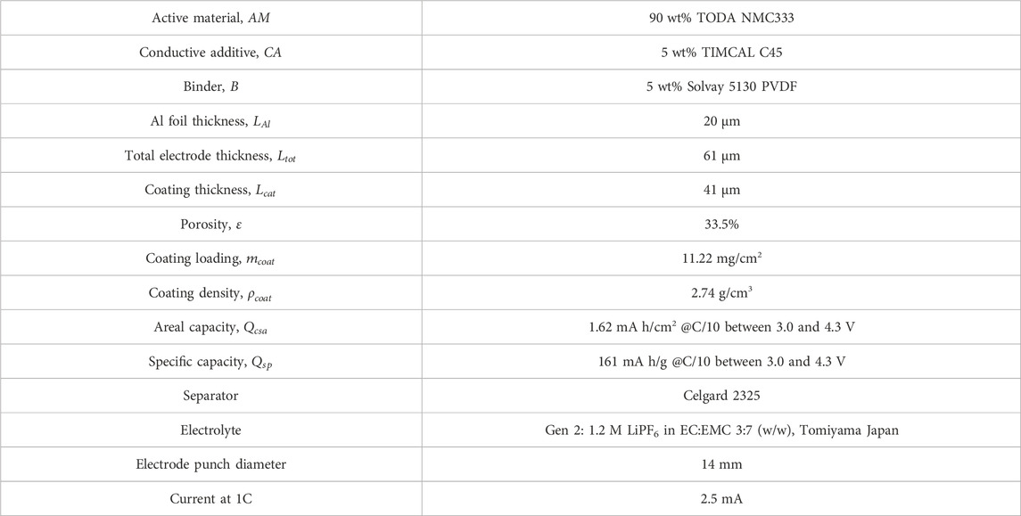
TABLE 1. Cycled NMC333 cathode design parameters.
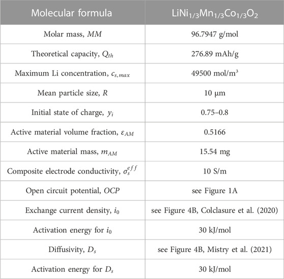
TABLE 2. Active material properties.
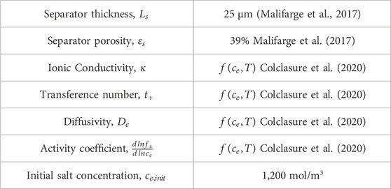
TABLE 3. Separator and electrolyte properties.
3 Results and discussion
The aim of this work was to develop and validate model-driven electrochemical relithiation protocols using a cathode material that was cycle aged in a controlled manner that avoided potential complicating factors such as mechanical degradation of the electrode or particle fracture to isolate LLI as the primary cause of capacity loss. To verify that the LLI was the main cause of capacity loss for the NMC cathode materials, thorough characterization of the surface chemistry, morphology and crystal structure of the cycled NMC 333 was compared to pristine NMC 333. Figure 1 shows SEM cross-sectional image of each type of NMC 333 particle in this study. Several SEM images of the cycle aged NMC 333 were compared to confirm that no advanced particle breakdown occurred during cycling. There is no obvious significant source of mechanical degradation in the cycle aged particles that could have a significant contribution to the capacity loss. The overall morphology and size of the pristine and cycled aged NMC 333 particles was similar. XRD was performed to characterize how cycle aging affected the crystal structure of the NMC 333 and is shown in Figure 2.
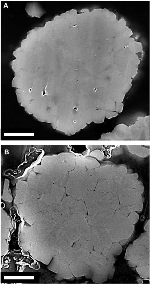
FIGURE 1. Cross-sectional SEM images of (A) Pristine, (B) Electrochemically aged NMC333 particles. The white scale bar is 2 µm.
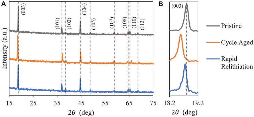
FIGURE 2. XRD analysis for NMC 333 materials with (A) all peaks, (B) (003) peaks.
The typical diffraction peaks associated with the
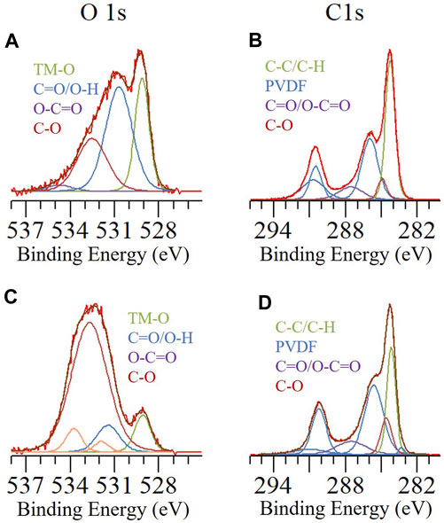
FIGURE 3. O1s and C1s XPS spectra for (A,B) Cycle aged and (C,D) Pristine NMC 333.
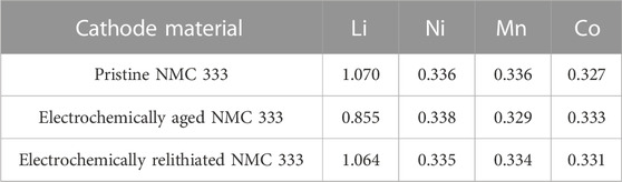
TABLE 4. Molar ratio of relevant components in cathode materials determined through ICP-OES.
Figure 4A shows the open circuit potential for the cycled NMC333 cathode material as a function of state of charge. Slow rate cycling of Li|NMC333 half-cell at C/20 was performed between 2.5 and 4.1 V at 30°C and 45°C to obtain the thermodynamic open circuit potential (see Figure 4A). At such slow rates, transport and kinetic limitations are negligible, consequently, the cell voltage can be directly correlated to the thermodynamic OCP of the cycled NMC333 material. Cathode is assumed to be fully lithiated at cell voltage of 2.5 V; subsequently, the capacity exchanged during half-cell discharge can be correlated to the cathode lithiation state of charge. OCPs for 30°C and 45°C overlap considerably with slight variation in the lithiation range 0.4 < SOC< 0.6 arising from entropic effects. Exchange current density and Li solid phase diffusivity variation with state of charge for the cycled material at varying temperatures is shown in Figure 4B. Verma and coworkers (Verma et al., 2017) have obtained the lithiation dependent exchange current density for pristine TODA NMC532 through galvanostatic intermittent titration test (GITT) which has been validated with extensive rate performance data by Colclasure et al. (Colclasure et al., 2020). We use this function multiplied by a factor of 0.75 utilizing the fact that NMC cathode properties improve with higher Ni content (333 < 532 < 622 < 811) (Noh et al., 2013) and degraded material performs worse than pristine; so degraded NMC333 should showcase inferior kinetics than pristine NMC532. Furthermore, the state of charge dependence of properties amongst NMC family of cathodes is very similar, so multiplying NMC532’s property with a fraction can capture the SOC dependence of NMC333 property well (Noh et al., 2013). Mistry and coworkers (Mistry et al., 2021) have identified the diffusivity function for pristine TODA NMC333 through curve fit to experimental data reported in Wu et al. (Wu et al., 2012). This pristine diffusivity is multiplied by a factor of 0.5 to obtain the degraded material’s diffusion coefficient. The exchange current density at 30°C drops monotonically from ∼0.4 to 0 A/m2 across the lithiation range 0.4 < SOC < 1. Kinetics gets enhanced with thermal effects according to the Arrhenius correlation, consequently, we see a bump in the exchange current density up to ∼0.6 A/m2 at 45°C. Diffusivity also shows a monotonic decline from ∼10−13 m2/s to ∼10−15 m2/s with lithiation (0.4 < SOC < 1) for both temperatures with a slight enhancement of diffusivity at 45°C. The factor magnitudes of 0.5 and 0.75 for diffusivity and exchange current density respectively provide best validation between the model and experiments with the least root mean square error (see Figure 5). Interestingly, both exchange current density and diffusivity show steeper declines close to full lithiation (∼SOC = 1). This sharp drop has an impact on performance. During half-cell discharge, a constant current (CC) relithiation protocol hits the lower voltage cutoff due to exacerbated kinetic, transport limitations without the cathode reaching full lithiation. The usage of a constant current constant voltage (CCCV) discharge can achieve full lithiation but sacrifices the time optimization aspect; the protocol must run for hours before full lithiation is achieved. Hence, we need a novel electrochemical protocol to circumvent the issues with CC or CCCV protocol.
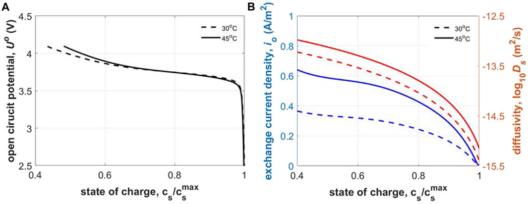
FIGURE 4. Thermodynamic, transport and kinetic properties of cycled NMC333 cathode: (A) open circuit potential, and (B) intercalation exchange current density and Li solid phase diffusivity.
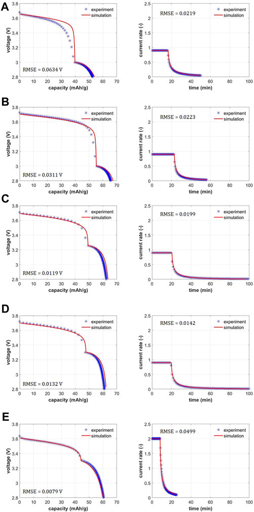
FIGURE 5. Performance model validation of voltage and current rates with experimental data for scanning voltage protocol: (A) 0.9C - 3.0 V–0.1 mV/s–2.8 V–30°C, (B) 0.9C - 3.0 V–0.1 mV/s–2.8 V–45°C, (C) 0.9C - 3.2 V–0.1 mV/s–2.8 V–45°C, (D) 0.9C - 3.3V–0.1 mV/s–2.8 V–45°C and (E) 2C - 3.3 V–0.5 mV/s–2.8 V–45°C.
The limitations of CC or CCCV electrochemical protocol can be eliminated through usage of novel electrochemical protocols including multistep currents and scanning voltage steps (Mai et al., 2020). A multistep protocol with stepwise reduction in currents accounting for the increasing sluggishness of kinetics, transport can sustain the discharge to full cathode lithiation while optimizing for time since there are no slow CV steps. However, application of the multistep current protocol for electrochemical testing is cumbersome; there is a current rate and voltage/time limit that needs to be defined for each step. The electrochemical protocol parameters can balloon for number of steps
Figures 5A–E showcase the experimental performance plots for variations of the scanning voltage protocol alongside the model validation. Experimental dataset for voltage vs. capacity is shown in Supplementary Figure S2 for all cases (with replicates) while Supplementary Figure S4 shows the average and standard deviation in the voltage and current profiles. Model is validated against the averaged experimental data. Voltage vs. specific capacity as well as current vs. time are validated between the experiments and the model. Low root mean square errors (RMSE) illuminate the high fidelity of the match. In Li-ion battery modeling literature, traditionally CC or CCCV models are used, and the validation is only shown for voltage vs. capacity (Ji et al., 2013; Verma et al., 2017). Here, we highlight the fact that in addition to the voltage - capacity data, the current rate - time data is also matched. Initial voltages lie around 3.6–3.7 V for the assembled half-cells with cycled NMC333 cathodes. This corresponds to Li state of charge in the cycled cathodes of around 0.80 which is close to the ratio of Li content in electrochemically aged sample versus pristine sample (0.855/1.07 ∼ 0.80). The first protocol variation is run at 30°C and constant current at 0.9C to 3.0 V with scanning voltage at 0.1 mV/s to 2.8 V (see Figure 5A). The relithiation time and capacity are 50 min and 52.62 mAh/g respectively. Subsequently, the relithiation temperature is increased to 45°C to leverage the enhanced transport and kinetics with same current and voltage steps (see Figure 5B). Relithiation time and capacity for this protocol are 56 min and 65.68 mAh/g respectively. Higher capacity and time duration indicate extra capacity is accessed due to the improved exchange current density and Li diffusivity. For the next variation (see Figure 5C), the scanning voltage step starts at 3.2 V instead of 3.0 V keeping other protocol parameters same as in Figure 5B. This increases the relithiation time considerably to 103 min while the relithiation capacity remains around the same ballpark (62.75 mAh/g). Evidently, earlier introduction of the scanning voltage step in the protocol from 3.0 to 3.2 V increases the time duration of the scan step and consequently the total time duration considerably (103 min vs. 56 min) while keeping the capacities similar. Changing the scan step start to 3.3 V (see Figure 5D, we see similar relithiation times and capacity of 103 min and 61.06 mA h/g. Finally, we increase the current rates to 2 C from 0.9 C and scan rate to 0.5 mV/s from 0.1 mV/s to see the optimal relithiation time of 25 min and relithiation capacity of 60.53 mAh/g which brings the cathode to near full lithiation.
To ascertain the efficacy of the constant current scanning voltage (CCSV) protocol, the performance model outputs of capacity and relithiation time are compared against baseline constant current (CC), constant current constant voltage protocol (CCCV) and a novel multistep constant current constant voltage protocol (multistep CCCV). We compare the results against the best scanning voltage validation case of 2C - 3.3 V–0.5 mV/s–2.8 V–45°C. The CC protocol consist of 2C current up to 2.8 V with the CCCV protocol comprising of an additional constant voltage step at 2.8 V until the current rate drops to C/100. Multistep CCCV protocol consists of several CC steps starting at 2C current rate. Each step has a duration of 2.5 min and a step down in current rate of 0.25C is prescribed at the end of each step. Once the voltage reaches the 2.8 V cutoff, an additional constant voltage step until the current rate drops to C/100 is also prescribed. Figures 6A, B shows the evolution of voltage and capacity with time for the CC, CCCV, multistep CCCV and CCSV protocols. CC, CCCV and CCSV protocols show smooth voltage decrease in the CC step while the multistep CCCV protocol shows the jagged voltage rise at end of each CC step from current step downs leading to lowered kinetic and transport overpotentials. Capacity increase with time for each protocol is relatively smooth with a change in slope observed at instants where the protocol switches to constant voltage, current step downs or scanning voltage steps. An interesting feature is that the slope of the constant voltage step in CCCV or multistep CCCV is smaller as compared to the scanning voltage step in CCSV. This is indicative of ability of the scanning voltage step to provide higher currents as compared to the constant voltage step. Total relithiation capacity and protocol runtime are shown in Figures 6C, D with the CCSV outperforming CC, CCCV and multistep CCCV in Li capacity restored. CC and multistep CCCV do show lower relithiation times as compared to CCSV but are only able to restore 73% and 92% of the total capacity lithiated in CCSV. Furthermore, multistep CCCV requires delineation of additional parameters like constant current step duration and constant current step-down magnitude, so it brings the number of parameters for protocol specification to 5 which is the same as for CCSV protocol. Consequently, it is advisable to use the CCSV protocol for cathode relithiation.
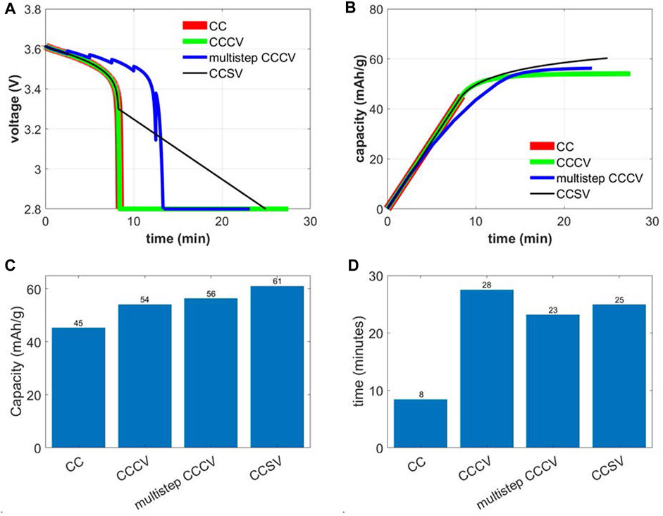
FIGURE 6. Comparison of constant current (2C to 2.8 V), constant current constant voltage (2C to 2.8V, hold at 2.8 V until C/100), multistep CCCV (2C for 2.5 min, 1.75 C for 2.5 min and so on to 2.8V, hold at 2.8 V until C/100) and constant current scanning voltage (2C - 3.3 V–0.5 mV/s–2.8 V–45°C) electrochemical protocol for relithiation of aged NMC333 cathode: (A) voltage vs. time, (B) relithiated capacity vs. time, (C) total relithiation capacity and (D) total relithiation time.
In an initial scoping of electrochemical protocol choice, CCCV and CCSV protocol were run on ∼25% capacity degraded NMC333 electrode with the experimental data for voltage, current vs. capacity and capacity vs. time shown in Figure S. CCCV protocol used 0.2C to 2.8V, hold at 2.8 V until current decays to C/100, while CCSV protocol parameters were 1.8C–3.0V–0.1 mV/s–2.8V–30°C. This data also afforded a preliminary indication into the efficacy of the scanning voltage step in reducing lithiation time. Approximately 19 mAh/g of lithiation was observed in the scan step from 3.0 to 2.8 V in 35 min for the CCSV protocol as opposed to 9.5 mAh/g of lithiation in 113 min in the constant voltage step at 2.8 V for the CCCV protocol. Thus, CV lithiation can be very sluggish.
Development of the high-fidelity performance model allows for running a parametric sweep of the constant current scanning voltage protocol to identify the best relithiation strategy. The parameters of interest are initial current rate, intermediate voltage cutoff and scan rate with temperature and final voltage cutoff fixed to 45°C and 2.8 V respectively. Figures 7A–D shows contour plots of relithiation time (left) and recovered capacity (right) for intermediate voltage cutoffs of 3.0–3.3 V as a function of the initial current rate and scan rate. For the full sweep, the C-rate is varied from 1C to 3C in increments of 0.5C while the scan rate is changed from 0.1 mV/s to 0.5 mV/s in increments of 0.1 mV/s. Regions of low relithiation time (t < 30 min) and high capacity (Q > 60 mA h/g) are demarcated by black lines in the contour plots. It is evident that the desirable current rate and scan rate zones in the time contour is nearly opposite to the optimal zones in the capacity plot. An intersection of the desirable zones in both contours marks the best relithiation protocol strategy. Based on this, a couple optimal protocols are highlighted using star symbols in each intermediate voltage cutoff parametric sweep. Figure 7A showcases that the protocols 1.5C–3.0V–0.2 mV/s–2.8V - 45°C and 2C–3.0V–0.2 mV/s–2.8V - 45°C can achieve relithiation times ∼30 min and capacity ∼60 mAh/g. The desirable time zone is big for 3.0 V intermediate cutoff because of the less time spent in the slow scanning voltage step. Consequently, the desirable capacity zone is smaller because of less time for relithiation as well. The optimal time zones shrink while the capacity zones grow as we move from 3.0 to 3.3 V intermediate cutoff. Nominal time spent in scan step increases from 0.2/SR to 0.5/SR for 3.0–3.3 V intermediate cutoff indicating a 250% rise in scan step duration.
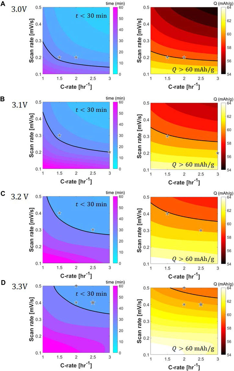
FIGURE 7. Contour plots for performance metrics, time of electrochemical relithiation in minutes (left) and relithiation capacity in mAh/g (right), for parametric sweeps of scanning voltage protocol constant current rate, scan rate and scan step initial voltage: (A) 3.0 V, (B) 3.1 V, (C) 3.2 V and (D) 3.3 V. Black line showcases protocol for which 30 min relithiation and 60 mA h/g capacity gain is achieved. Optimal relithiation protocol showcases relithiation times
Optimal protocols for 3.1 V intermediate cutoff are ascertained to be 1.5C–3.1V–0.3 mV/s–2.8V - 45°C and 3C–3.1V–0.2 mV/s–2.8V - 45°C. When the current rate increases, constant current step time duration decreases, consequently, the scan rate can be decreased to maintain high capacities while satisfying the time constraint. For 3.2 V intermediate cutoff, the optimal protocols are 1.5C–3.2V–0.4 mV/s–2.8V - 45°C and 2.5C–3.2V–0.3 mV/s–2.8V - 45°C. As the intermediate cutoff increases, the scan rates can be increased to shorten the relithiation time while getting good capacities. Finally, three optimal protocols are delineated for the 3.3 V cutoff: 2C–3.3V–0.5 mV/s–2.8 V - 45°C, 2C–3.3V–0.4 mV/s–2.8V - 45°C and 2.5C–3.3V–0.4 mV/s–2.8V - 45°C. The cycle aged NMC333 material was electrochemically relithiated with the latter protocol showcasing good performance when rebuilt into a half cell in Supplementary Figure S5. The cycle aged NMC333 that was relithiated with the rapid scanning voltage protocol was also analyzed with XRD and ICPOES. Figure 2 shows that the (003) for the relithiated NMC333 materials shifts back to a higher angle reflecting a decrease in the c lattice constant due to the increased lithium content that overlaps with the (003) peak for pristine NMC333. The ICPOES results in Table 4 also demonstrate over 99% of the initial lithium content was restored. The cycle aged NMC333 material was electrochemically relithiated with the latter protocol showcasing good performance when rebuilt into a half cell with reversible third cycle charge capacity of 161 mAh/g which is comparable with pristine NMC333. The first charge capacity of the relithiated material in half cells was consistently about 98% of pristine NMC 333 which agrees with the ICP and XRD results. Representative voltage profiles for half cells of pristine NMC 333 and relithiated cycle aged NMC 333 are shown in Figures 8A, B. The electrochemically relithiated NMC 333 was also rebuilt into full cells and cycled at C/3 with C/10 cycles every 50 cycles with comparable performance to pristine NMC 333 as shown in Figure 8C. The relithiated NMC 333 material in this study in half cell and full cell cycling had first charge capacities that were consistently <3% lower than pristine NMC 333. To reach 100% pristine performance in NMC materials that are likely to have degradation modes outside of just LLI, a high temperature annealing step will likely be necessary. An annealing step was outside the scope of this work which was constrained to developing a rapid electrochemical relithiation protocol for end-of-life cathodes without any delamination or separation step for the cycle aged NMC powder. This limited the annealing options post-relithiation due to concerns regarding the thermal stability of the copper current collector. Consequently, we demonstrated successful development of a direct recycling method using model optimized electrochemical relithiation for end-of-life battery cathodes.
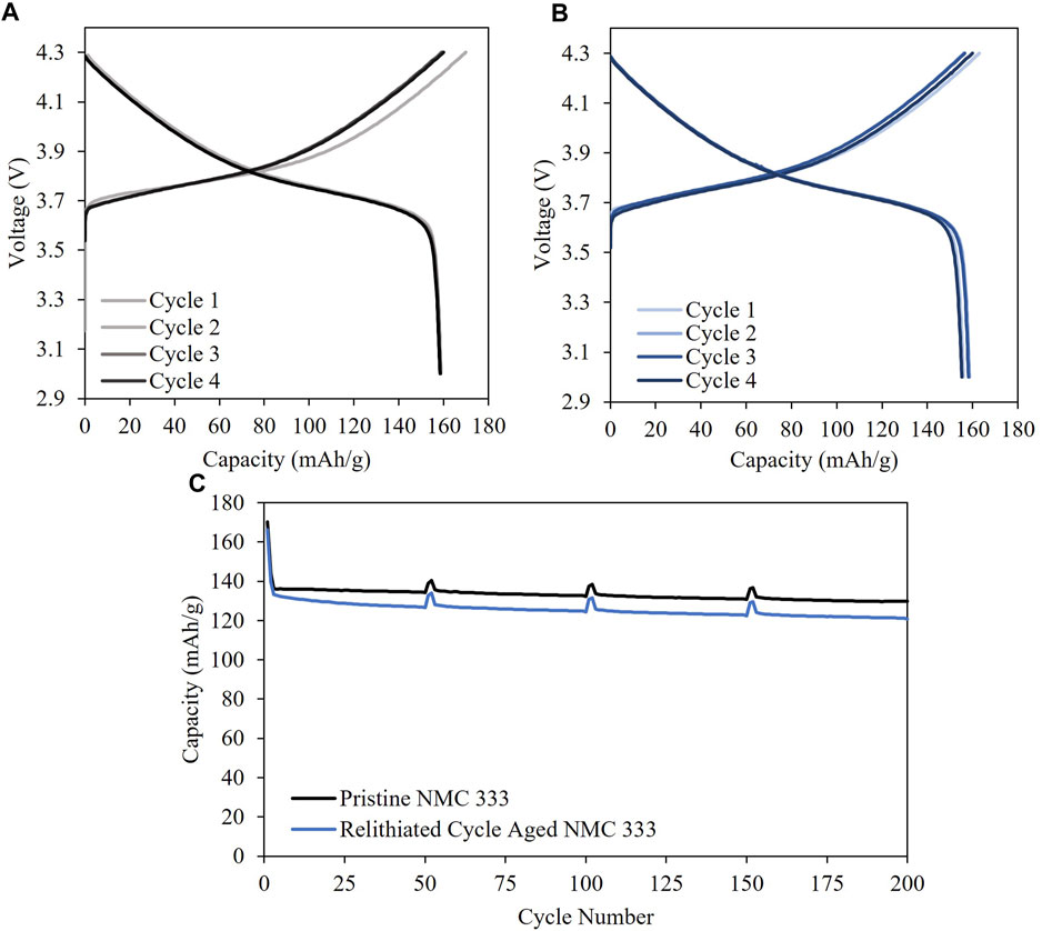
FIGURE 8. Half cell C/10 cycling of (A) Pristine NMC 333 and (B) Relithiated cycle aged NMC 333 and (C) full cell cycling of relithiated cycle aged NMC 333.
4 Conclusion
A novel model-driven process for developing electrochemical relithiation protocols for lightly degraded NMC333 materials was presented. Advanced protocols using constant current scanning voltage discharge was shown to relithiate the degraded NMC333 to near full lithiation within 30 min. Reversible cycling of the relithiated materials was equivalent to pristine NMC333. Electrochemical relithiation is an excellent option for NMC cathode materials that have not undergone extensive mechanical degradation or surface structure degradation such as cation mixing. High Ni NMC cathodes like NMC622, NMC811 are prone to such degradations and hence electrochemical relithiation is hypothesized to be challenging for them. Other materials that will likely benefit from electrochemical relithiation include LFP or LCO since they also reach end-of-life predominantly by loss of lithium inventory to the solid electrolyte interphase instead of loss of active material from particle cracking (Spotnitz, 2003; Sarasketa-Zabala et al., 2015). Future work will focus on how to translate batch results into roll to roll format. Techno-economic modelling is needed to understand the strengths and weakness of electrochemical relithiation compared to other techniques.
Data availability statement
The original contributions presented in the study are included in the article/Supplementary Material, further inquiries can be directed to the corresponding author.
Author contributions
AV: Conceptualization, Methodology, Visualization, Writing–original draft. AC: Funding acquisition, Supervision, Writing–review and editing. JC: Conceptualization, Investigation, Project administration, Validation, Visualization, Writing–original draft.
Funding
The authors declare financial support was received for the research, authorship, and/or publication of this article. This work was authored by the National Renewable Energy Laboratory (NREL), operated by Alliance for Sustainable Energy, LLC, for the U.S. Department of Energy (DOE) under Contract No. DE- AC36–08GO28308.
Acknowledgments
All of this work was performed through the ReCell Center, which gratefully acknowledges support from the U.S. Department of Energy (DOE), Office of Energy Efficiency and Renewable Energy, and the Vehicle Technologies Office. The U.S. Government retains and the publisher, by accepting the article for publication, acknowledges that the U.S. Government retains a nonexclusive, paid-up, irrevocable, worldwide license to publish or reproduce the published form of this work, or allow others to do so, for U.S. Government purposes.
Conflict of interest
The authors declare that the research was conducted in the absence of any commercial or financial relationships that could be construed as a potential conflict of interest.
Publisher’s note
All claims expressed in this article are solely those of the authors and do not necessarily represent those of their affiliated organizations, or those of the publisher, the editors and the reviewers. Any product that may be evaluated in this article, or claim that may be made by its manufacturer, is not guaranteed or endorsed by the publisher.
Author disclaimer
The views expressed in the article do not necessarily represent the views of the DOE or the U.S. Government.
Supplementary material
The Supplementary Material for this article can be found online at: https://www.frontiersin.org/articles/10.3389/fbael.2023.1293939/full#supplementary-material
References
Chen, C.-H., Brosa Planella, F., O’regan, K., Gastol, D., Widanage, W. D., and Kendrick, E. (2020). Development of experimental techniques for parameterization of multi-scale lithium-ion battery models. J. Electrochem. Soc. 167 (8), 080534. doi:10.1149/1945-7111/ab9050
Colclasure, A. M., Tanim, T. R., Jansen, A. N., Trask, S. E., Dunlop, A. R., Polzin, B. J., et al. (2020). Electrode scale and electrolyte transport effects on extreme fast charging of lithium-ion cells. Electrochimica Acta 337, 135854. doi:10.1016/j.electacta.2020.135854
Coyle, J., Fink, K., Colclasure, A., and Keyser, M. (2023). Recycling electric vehicle batteries: opportunities and challenges. AM&P Tech. Artic. 181 (5), 19–23. doi:10.31399/asm.amp.2023-05.p019
Doyle, M., Fuller, T. F., and Newman, J. (1993). Modeling of galvanostatic charge and discharge of the lithium/polymer/insertion cell. J. Electrochem. Soc. 140 (6), 1526–1533. doi:10.1149/1.2221597
Duca, M. D., Plosceanu, C. L., and Pop, T. (1998). Surface modifications of polyvinylidene fluoride (PVDF) under rf Ar plasma. Polym. Degrad. Stab. 61 (1), 65–72. doi:10.1016/S0141-3910(97)00130-4
Dufek, E. J., Abraham, D. P., Bloom, I., Chen, B.-R., Chinnam, P. R., Colclasure, A. M., et al. (2022). Developing extreme fast charge battery protocols–A review spanning materials to systems. J. Power Sources 526, 231129. doi:10.1016/j.jpowsour.2022.231129
Gaines, L., Dai, Q., Vaughey, J. T., and Gillard, S. (2021). Direct recycling R&D at the ReCell center. Recycling 6 (2), 31. doi:10.3390/recycling6020031
Gao, H., Yan, Q., Xu, P., Liu, H., Li, M., Liu, P., et al. (2020). Efficient direct recycling of degraded LiMn2O4 cathodes by one-step hydrothermal relithiation. ACS Appl. Mater. Interfaces 12 (46), 51546–51554. doi:10.1021/acsami.0c15704
Guo, M., Sikha, G., and White, R. E. (2011). Single-particle model for a lithium-ion cell: thermal behavior. J. Electrochem. Soc. 158 (2), A122. doi:10.1149/1.3521314
Ji, Y., Zhang, Y., and Wang, C.-Y. (2013). Li-ion cell operation at low temperatures. J. Electrochem. Soc. 160 (4), A636–A649. doi:10.1149/2.047304jes
Jia, T., Zhong, G., Lv, Y., Li, N., Liu, Y., Yu, X., et al. (2023). Prelithiation strategies for silicon-based anode in high energy density lithium-ion battery. Green Energy & Environ. 8 (5), 1325–1340. doi:10.1016/j.gee.2022.08.005
Kim, H. J., Choi, S., Lee, S. J., Seo, M. W., Lee, J. G., Deniz, E., et al. (2016). Controlled prelithiation of silicon monoxide for high performance lithium-ion rechargeable full cells. Nano Lett. 16 (1), 282–288. doi:10.1021/acs.nanolett.5b03776
Lahtinen, K., Rautama, E. L., Jiang, H., Räsänen, S., and Kallio, T. (2021). Reuse of LiCoO2 electrodes collected from spent Li-ion batteries after electrochemical Re-lithiation of the electrode. ChemSusChem 14 (11), 2434–2444. doi:10.1002/cssc.202100629
Li, X., Dogan, F., Lu, Y., Antunes, C., Shi, Y., Burrell, A., et al. (2020). Fast determination of lithium content in spent cathodes for direct battery recycling. Adv. Sustain. Syst. 4 (8), 2000073. doi:10.1002/adsu.202000073
Liu, H., Chen, Y., Hy, S., An, K., Venkatachalam, S., Qian, D., et al. (2016). Operando lithium dynamics in the Li-rich layered oxide cathode material via neutron diffraction. Adv. Energy Mater. 6 (7), 1502143. doi:10.1002/aenm.201502143
Liu, Z., Zhang, C., Ye, M., Li, H., Fu, Z., Zhang, H., et al. (2022). Closed-loop regeneration of a spent LiFePO4 cathode by integrating oxidative leaching and electrochemical relithiation. ACS Appl. Energy Mater. 5 (11), 14323–14334. doi:10.1021/acsaem.2c02883
Mai, W., Colclasure, A. M., and Smith, K. (2020). Model-instructed design of novel charging protocols for the extreme fast charging of lithium-ion batteries without lithium plating. J. Electrochem. Soc. 167 (8), 080517. doi:10.1149/1945-7111/ab8c84
Malifarge, S., Delobel, B., and Delacourt, C. (2017). Guidelines for the analysis of data from the potentiostatic intermittent titration technique on battery electrodes. J. Electrochem. Soc. 164 (14), A3925–A3932. doi:10.1149/2.1591714jes
Mistry, A., Trask, S., Dunlop, A., Jeka, G., Polzin, B., Mukherjee, P. P., et al. (2021). Quantifying negative effects of carbon-binder networks from electrochemical performance of porous li-ion electrodes. J. Electrochem. Soc. 168 (7), 070536. doi:10.1149/1945-7111/ac1033
Mohanty, D., Kalnaus, S., Meisner, R. A., Rhodes, K. J., Li, J., Payzant, E. A., et al. (2013). Structural transformation of a lithium-rich Li1.2Co0.1Mn0.55Ni0.15O2 cathode during high voltage cycling resolved by in situ X-ray diffraction. J. Power Sources 229, 239–248. doi:10.1016/j.jpowsour.2012.11.144
Nie, H., Xu, L., Song, D., Song, J., Shi, X., Wang, X., et al. (2015). LiCoO2: recycling from spent batteries and regeneration with solid state synthesis. Green Chem. 17 (2), 1276–1280. doi:10.1039/c4gc01951b
Noh, H.-J., Youn, S., Yoon, C. S., and Sun, Y.-K. (2013). Comparison of the structural and electrochemical properties of layered Li [NixCoyMnz] O2 (x= 1/3, 0.5, 0.6, 0.7, 0.8 and 0.85) cathode material for lithium-ion batteries. J. power sources 233, 121–130. doi:10.1016/j.jpowsour.2013.01.063
Overhoff, G. M., Nölle, R., Siozios, V., Winter, M., and Placke, T. (2021). A thorough analysis of two different pre-lithiation techniques for silicon/carbon negative electrodes in lithium ion batteries. Batter. Supercaps 4 (7), 1163–1174. doi:10.1002/batt.202100024
Park, K., Yu, J., Coyle, J., Dai, Q., Frisco, S., Zhou, M., et al. (2021). Direct cathode recycling of end-of-life Li-ion batteries enabled by redox mediation. ACS Sustain. Chem. Eng. 9 (24), 8214–8221. doi:10.1021/acssuschemeng.1c02133
Raj, B., Sahoo, M. K., Nikoloski, A., Singh, P., Basu, S., and Mohapatra, M. (2022). Retrieving spent cathodes from lithium-ion batteries through flourishing Technologies. Batter. Supercaps 6, e202200418. doi:10.1002/batt.202200418
Richa, K., Babbitt, C. W., Gaustad, G., and Wang, X. (2014). A future perspective on lithium-ion battery waste flows from electric vehicles. Resour. Conservation Recycl. 83, 63–76. doi:10.1016/j.resconrec.2013.11.008
Sarasketa-Zabala, E., Aguesse, F., Villarreal, I., Rodriguez-Martinez, L., López, C. M., and Kubiak, P. (2015). Understanding lithium inventory loss and sudden performance fade in cylindrical cells during cycling with deep-discharge steps. J. Phys. Chem. C 119 (2), 896–906. doi:10.1021/jp510071d
Shaju, K. M., Subba Rao, G. V., and Chowdari, B. V. R. (2002). Performance of layered Li(Ni1/3Co1/3Mn1/3)O2 as cathode for Li-ion batteries. Electrochimica Acta 48 (2), 145–151. doi:10.1016/S0013-4686(02)00593-5
Spotnitz, R. (2003). Simulation of capacity fade in lithium-ion batteries. J. Power Sources 113 (1), 72–80. doi:10.1016/s0378-7753(02)00490-1
Srinivasan, V., and Newman, J. (2004). Discharge model for the lithium iron-phosphate electrode. J. Electrochem. Soc. 151 (10), A1517. doi:10.1149/1.1785012
Verma, A., Smith, K., Santhanagopalan, S., Abraham, D., Yao, K. P., and Mukherjee, P. P. (2017). Galvanostatic intermittent titration and performance based analysis of LiNi0. 5Co0. 2Mn0. 3O2 cathode. J. Electrochem. Soc. 164 (13), A3380–A3392. doi:10.1149/2.1701713jes
Wang, A., O'Kane, S., Brosa Planella, F., Houx, J. L., O'Regan, K., Zyskin, M., et al. (2022). Review of parameterisation and a novel database (LiionDB) for continuum Li-ion battery models. Prog. Energy 4, 032004. doi:10.1088/2516-1083/ac692c
Wang, T., Luo, H., Bai, Y., Li, J., Belharouak, I., and Dai, S. (2020). Direct recycling of spent NCM cathodes through ionothermal lithiation. Adv. Energy Mater. 10 (30), 2001204. doi:10.1002/aenm.202001204
Wu, S.-L., Zhang, W., Song, X., Shukla, A. K., Liu, G., Battaglia, V., et al. (2012). High rate capability of Li (Ni1/3Mn1/3Co1/3) O2 electrode for Li-ion batteries. J. Electrochem. Soc. 159 (4), A438–A444. doi:10.1149/2.062204jes
Yang, J., and Xia, Y. (2016). Suppressing the phase transition of the layered Ni-rich oxide cathode during high-voltage cycling by introducing low-content Li2MnO3. ACS Appl. Mater. Interfaces 8 (2), 1297–1308. doi:10.1021/acsami.5b09938
Yang, T., Lu, Y., Li, L., Ge, D., Yang, H., Leng, W., et al. (2020). An effective relithiation process for recycling lithium-ion battery cathode materials. Adv. Sustain. Syst. 4 (1), 1900088. doi:10.1002/adsu.201900088
Keywords: direct recycling, electrochemical relithiation, lithium-ion battery, advanced protocols, cathode
Citation: Verma A, Colclasure AM and Coyle J (2023) Developing rapid electrochemical relithiation protocols for scalable relithiation of lithium-ion battery cathode materials. Front. Batteries Electrochem. 2:1293939. doi: 10.3389/fbael.2023.1293939
Received: 13 September 2023; Accepted: 13 November 2023;
Published: 29 November 2023.
Edited by:
Candace K. Chan, Arizona State University, United StatesReviewed by:
Naoto Kitamura, Tokyo University of Science, JapanDong Hou, University of Louisiana at Lafayette, United States
Copyright © 2023 Verma, Colclasure and Coyle. This is an open-access article distributed under the terms of the Creative Commons Attribution License (CC BY). The use, distribution or reproduction in other forums is permitted, provided the original author(s) and the copyright owner(s) are credited and that the original publication in this journal is cited, in accordance with accepted academic practice. No use, distribution or reproduction is permitted which does not comply with these terms.
*Correspondence: Jaclyn Coyle, amNveWxlQG5yZWwuZ292
†These authors have contributed equally to this work and share first authorship