- Department of Architecture and Architectural Engineering, Graduate School of Engineering, Kyoto University, Kyoto, Japan
A new method for optimal viscous damper placement is proposed for elastic-plastic multi-degree-of-freedom (MDOF) structures subjected to the critical double impulse as a representative of near-fault ground motions. The double impulse consists of two impulses with different directions and the critical interval between those two impulses is characterized by the criterion on the maximum input energy that is expected to lead to the maximum deformation. The critical timing of the second impulse is the timing at which the sum of the restoring force and the damping force in the first story attains zero. The objective function and constraint in terms of the maximum interstory drift along the building height or the sum of the maximum interstory drifts in all stories are selected and the corresponding optimization algorithm based on time-history response analysis and sensitivity analysis is investigated. Since the objective function in terms of the sum of the maximum interstory drifts in all stories is superior to the objective function in terms of the maximum interstory drift along the building height, it is employed in this paper. A new concept of double impulse pushover (DIP) is proposed for determining the input velocity level of the critical double impulse. It is demonstrated that the combination of two algorithms, one for effective reduction of the overflowed maximum interstory drift via the concentrated allocation of dampers and the other for effective allocation of dampers via the use of stable objective function, is effective for finding a stable optimal damper placement.
Introduction
Viscous dampers such as oil dampers are passive dampers effective for broader amplitude ranges under the condition that the stiffness is not added. This property is advantageous in most structural design of framed building structures because the change of stiffness in building structures usually leads to the variation of design loads and the necessity of change of member size. Various theories of optimal damper have been proposed (see Takewaki, 2009; Domenico et al., 2019).
In an early stage, most research is limited to elastic problems. Zhang and Soong (1992) proposed a simple algorithm to insert dampers sequentially into the location exhibiting the maximum response. Tsuji and Nakamura (1996) presented an optimality condition-based sequential algorithm for optimal damper placement. Takewaki (1997) proposed an incremental inverse problem approach to the investigation of optimal damper placement by using the transfer function as an objective performance. Takewaki et al. (1999) introduced a sensitivity-based approach in the field of optimal damper placement. Garcia (2001) extended the approach by Zhang and Soong (1992) and compared the optimization performances of several algorithms. Singh and Moreschi (2001) investigated optimal design problems using the optimality conditions and the non-linear programming. Uetani et al. (2003) presented a practical and general damper optimization method for framed structures based on the mathematical programing. Lavan and Levy (2006) investigated a methodology for the optimal design of added viscous damping for an ensemble of realistic ground motion records with a constraint on the maximum drift. They transformed the original problem into some equivalent problems. Silvestri and Trombetti (2007) proposed physical and numerical approaches for the optimal insertion of seismic viscous dampers in shear-type structures and compared the optimization performances of several algorithms. Aydin et al. (2007) investigated the optimal damper distribution for seismic rehabilitation of planar building structures. Whittle et al. (2012) compared some viscous damper placement methods for improving seismic building design.
As far as non-linear dampers or non-linear structures with dampers are concerned, a limited number of researches has been proposed. Lavan and Levy (2005) investigated a problem of optimal design of supplemental viscous dampers for irregular shear-frames in the presence of yielding. Attard (2007) investigated a problem of optimal viscous damping for controlling interstory displacements in highly non-linear steel buildings. Lavan et al. (2008) proposed a non-iterative optimization procedure for seismic weakening and damping of inelastic structures. Adachi et al. (2013) proposed a practical theory of optimal relief-force distribution for oil dampers by setting the maximum interstory drift and the maximum building-top acceleration as the objective performances. Murakami et al. (2013) treated a problem of simultaneous optimal damper placement using oil, hysteretic and inertial mass dampers and proposed a sensitivity-based algorithm. The cost ratio among oil, hysteretic and inertial mass dampers may be a key point in such problem. In addition, the irregular unstable sensitivity for hysteretic dampers and recorded earthquake ground motions seems to be a difficult but challenging issue. Pollini et al. (2017) dealt with a problem of optimal placement of non-linear viscous dampers by using the adjoint sensitivity analysis method. Shiomi et al. (2018) investigated a problem of optimal hysteretic damper placement for elastic-plastic multi-degree-of-freedom (MDOF) shear building models under the double impulse as a representative of near-fault ground motions and proposed a sensitivity-based method. Their approach set the shear building model with uniform damper distribution as an initial design and reduces the unnecessary dampers based on the sensitivity information.
However, there is no method that enables an efficient analysis of optimal viscous damper placement for MDOF building structures experiencing rather large plastic deformation.
In this paper, a new method for optimal viscous damper placement is proposed for elastic-plastic MDOF shear building structures subjected to the critical double impulse as a representative of near-fault ground motions. The critical interval between two impulses of the double impulse is characterized by the criterion on the maximum input energy. The critical timing of the second impulse is proved to be the timing at which the sum of the restoring force and the damping force in the first story attains zero. The objective function and constraint in terms of the maximum interstory drift along the building height or the sum of the maximum interstory drifts in all stories are selected and the corresponding optimization algorithm based on time-history response analysis and sensitivity analysis is investigated. Since the objective function in terms of the sum of the maximum interstory drifts in all stories is superior to the objective function in terms of the maximum interstory drift along the building height, it is employed in this paper. A new concept called the double impulse pushover (DIP), an extended version of incremental dynamic analysis (IDA) by Vamvatsikos and Cornell (2001), is proposed for determining the input velocity level of the critical double impulse. It is demonstrated that the combination of two algorithms, one for effective reduction of the overflowed maximum interstory drift via the concentrated allocation of dampers and the other for effective allocation of dampers via the use of stable objective function, is effective for finding a stable optimal damper placement.
Although the proposed two algorithms are useful, the limitation is that both algorithms deal with the inter-story drift only and do not account for the inter-story velocity which is also critical for damping device placement. For further development, the related works (Hatzigeorgiou and Pnevmatikos, 2014; Papagiannopoulos et al., 2018) discussing this limitation should be investigated.
Double Impulse and Its Critical Input Timing
It is well-known that earthquake ground motions are uncertain in occurrence and properties (see Abrahamson et al., 1998). On the other hand, it is also well-recognized that near-fault ground motions possess peculiar characteristics, e.g., pulse-type waves (Bertero et al., 1978; Mavroeidis and Papageorgiou, 2003; Ozturk, 2003; Kalkan and Kunnath, 2006). To model such peculiar characteristics of near-fault ground motions, Kojima and Takewaki (2015) introduced the double impulse as a representative of the pulse-type main portion of near-fault ground motions. The acceleration of the double impulse with the time interval t0 of two impulses can be expressed by
where V is the input velocity amplitude and δ(t) is the Dirac delta function. Figure 1A shows the acceleration, velocity and displacement of the double impulse together with those of the corresponding one-cycle sine wave of acceleration. While several investigations using the double impulse have been made for single-degree-of-freedom (SDOF) models (Kojima and Takewaki, 2015, 2016; Kojima et al., 2017; Akehashi et al., 2018a,b), researches on MDOF models are few (Taniguchi et al., 2016; Saotome et al., 2018; Shiomi et al., 2018). This is due to the fact that the simple energy balance law for the simple derivation of the maximum response is difficult to apply for MDOF models because of the phase lag. Taniguchi et al. (2016) treated an undamped 2DOF elastic-plastic model under the double impulse and found by using the criterion of the maximum input energy that the timing of the second impulse at the zero restoring-force state becomes the critical timing. However, this critical timing cannot be used for damped models.
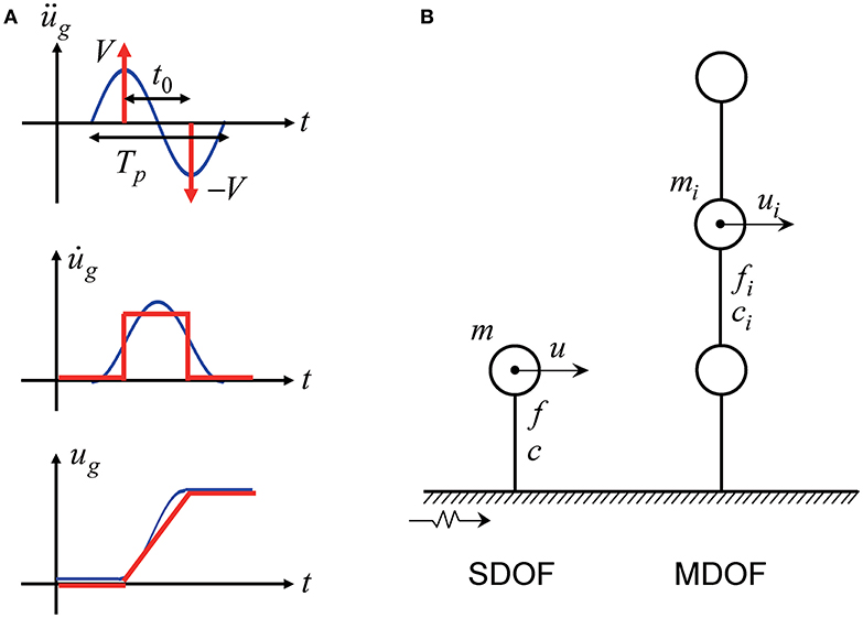
Figure 1. Double impulse and structural models, (A) Acceleration, velocity, and displacement of the double impulse and the corresponding one-cycle sine wave, (B) SDOF model and MDOF model.
Consider an SDOF elastic perfectly-plastic model with viscous damping and a MDOF elastic perfectly-plastic model with viscous damping as shown in Figure 1B. Let us consider first the SDOF model subjected to the double impulse. The critical input timing of the second impulse can be defined as the timing which maximizes the input energy by the second impulse. To demonstrate this fact, consider the following equation of motion.
where m, c, f, k, u, dy, dr denote the mass, damping coefficient, restoring force, initial stiffness, displacement, yield displacement and residual displacement. The super dot indicates the differentiation with respect to time. Assume that this SDOF model is subjected to the double impulse and the free vibration occurs. Since the displacement does not change instantaneously at the second impulse, the strain energy does not change at the second impulse. Therefore, the input energy by the second impulse can be expressed by
where is the velocity just before the input of the second impulse. Equation (3) indicates that, when the velocity attains the maximum, the input energy by the second impulse yields the maximum. The condition that attains the extremum is ü = 0. Substitution of ü = 0 into Equation (2) leads to . This means that, when the sum of the restoring force and the damping force becomes zero (i.e., the velocity becomes the maximum), the input energy by the second impulse becomes the maximum.
Consider next an N-story MDOF shear building model of mass mi in the i-th story. Let ui denote the horizontal displacement of mass mi. As in the SDOF model, since the displacements do not change instantaneously at the action of the second impulse, the strain energy does not change at the second impulse. Therefore, the input energy by the second impulse can be expressed by
Equation (4) means that, when attains the maximum, the input energy by the second impulse becomes the maximum. The condition that attains the extremum is . Since is equal to owing to the dynamic equilibrium, i.e., the sum of the damping force and the restoring force in the first story, the extremum condition becomes . This critical condition is very simple and can be used in the time-history response analysis in a simple manner.
Figure 2 shows an example of the time history of for the model subjected to the first single impulse and the variation of the input energy E by the second impulse with respect to t0.
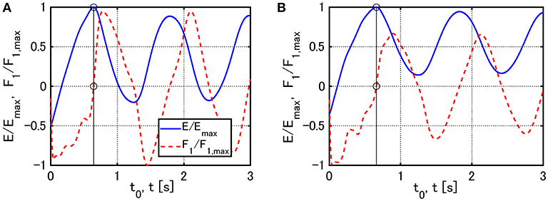
Figure 2. Examples of the time history of for the model subjected to the first single impulse and the variation of the input energy E by the second impulse with respect to t0: (A) V = 0.84 [m/s], (B) V = 1.23[m/s].
It seems important to investigate the correspondence of the double impulse with recorded ground motions, the Rinaldi Station FN component (Northridge 1994) was used (see Appendix).
Problem of Optimal Damper Placement and Algorithm of Solution
The direct problem of optimal damper placement may be stated as follows: To minimize the maximum interstory drift (or the sum of the maximum interstory drifts along height) under the condition on the specified total quantity of passive dampers. Another problem may be described as: To minimize the total quantity of passive dampers under the constraint on the maximum interstory drift. These two problems may be proved to be almost equivalent. It seems possible to deal with these problems by using the sensitivity-based approach that includes the time-history response analysis for the double impulse and the finite difference method. However, it was found that the direct application of this approach to the above mentioned problems leads to unstable results. To overcome this difficulty, a mixed-type approach including the following two problems (Problem 1 and 2) is proposed in this paper. The problems treated here will be explained next.
Consider first the following problem.
Problem 1
In Problems 1, cadd is the damping coefficient vector for added dampers in all stories and 1 is the vector including one in all components. The superscript T indicates the transpose. dmax,i is the maximum interstory drift in the i-th story under the critical double impulse and dtarget,i is the target value of dmax,i. The solution algorithm for this problem may be described as follows.
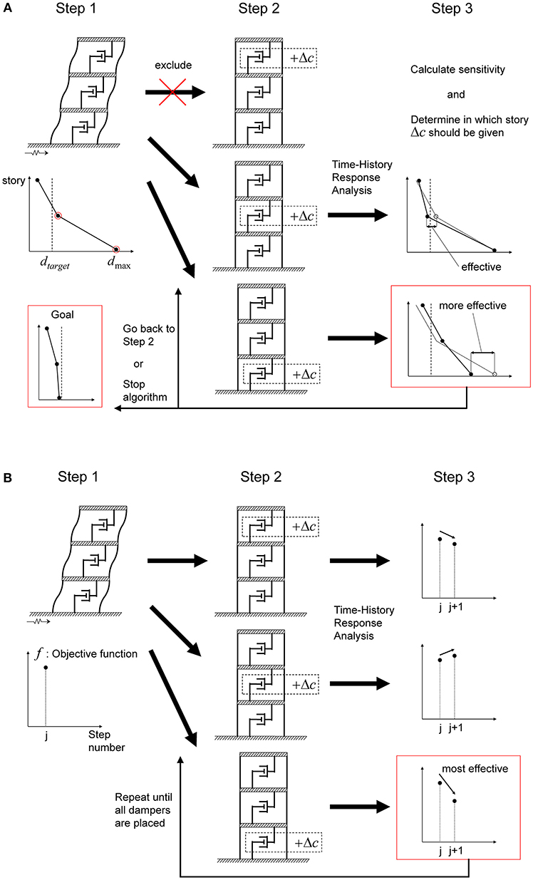
Algorithm 1
Step 1 Input the critical double impulse to the bare MDOF model and compute the maximum interstory drifts. Put j → 0.
Step 2 Investigate the stories i that satisfy . Add the small damping coefficient Δc only in the i-th story. Input the critical double impulse to the modified MDOF model and compute the maximum interstory drifts. Evaluate the sensitivity by the finite difference method.
Step 3 Find the largest value of and update the damping coefficient as ci → ci + Δc. If the model satisfies dmax,i ≤ dtarget,i for all i, then finalize the process. If not, put j → j + 1 and return to Step 2.
The flow of Algorithm 1 is shown in Figure 3A. Algorithm 1 is intended to implement the effective reduction of the overflowed maximum interstory drift (the stories i in Step 2) via the concentrated allocation of dampers. It was found after some attempts that Algorithm 1 sometimes encounters difficulties, i.e., inability to deal with the problem for a prescribed damper quantity.
Consider secondly the following problem.
Problem 2
The solution algorithm for this problem may be described as follows.
Algorithm 2
Step 1 Input the critical double impulse to the bare MDOF model and compute the objective function f. Put j → 0.
Step 2 Make N models in each of which Δc is added in one of the first through N-th stories. Input the critical double impulse to each of those MDOF models and compute the objective function f.
Step 3 Find the story in which the largest reduction of f occurs. For that story i, update the damping coefficient as ci → ci+Δc. Put j → j+1. If is satisfied, then finalize the process. If is satisfied, return to Step 2.
The flow of Algorithm 2 is shown in Figure 3B. It was found after some attempts that Algorithm 2 sometimes encounters difficulties in efficiency depending on models. The detailed explanation will be shown in numerical examples afterwards.
Consider thirdly the following mixed problem.
Problem 3: Mixed Problem of Problem 1 & Problem 2
Problem 1 is solved at first until some stage and then Problem 2 is solved.
The solution algorithm for this problem may be described as follows.
Algorithm 3: Combination of Algorithm 1 & Algorithm 2
First of all, apply Algorithm 1. Set dtarget,i = dy,i for all i and obtain the model in which the largest interstory drift attains the elastic limit. Adopt this model as another initial model and repeat Algorithm 2 in steps.
Algorithm 3 is superior to Algorithm 1 and 2 because the combination of two algorithms, one for effective reduction of the overflowed maximum interstory drift via the concentrated allocation of dampers and the other for effective allocation of dampers via the use of stable objective function, is effective for finding a stable optimal damper placement.
Models for Numerical Examples
Consider three models of 12 stories with different story stiffness distributions. Model 1 has a uniform distribution of story stiffnesses. Model 2 has a straight-line lowest eigenmode. Model 3 has stepped distribution of story stiffnesses (upper four stories, middle four stories and lower four stories have uniform stiffness distributions with different values/ the ratios among them are 1: 1.5: 2). The undamped fundamental natural period of these three models is 1.2 [s] and the structural damping ratio is 0.01 (stiffness proportional type). All the floor masses have the same value. The common story height is 4 [m] and the common yield interstory drift ratio is 1/150. The story shear-interstory drift relation obeys the elastic perfectly-plastic rule.
Figure 4 shows the eigenmodes multiplied by the participation factor (participation vectors) and the natural periods for three models.
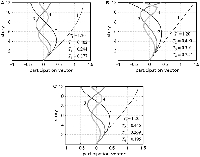
Figure 4. Eigenmodes multiplied by participation factors (participation vectors) and natural periods for three models: (A) Model 1, (B) Model 2, (C) Model 3.
Dynamic Pushover Analysis Under Amplified Critical Double Impulse
To determine the input velocity level of the critical double impulse, the incremental dynamic analysis (IDA) procedure (Vamvatsikos and Cornell, 2001) is applied to the critical double impulse. It should be reminded that only the critical double impulse is treated here, i.e., the interval of two impulses of the double impulse is varied depending on the input velocity level (also depending on the maximum interstory drift). We call this procedure “Double impulse pushover (DIP)”. DIP provides the relation between the maximum interstory drift and the input velocity level of the critical double impulse. While the conventional IDA includes multiple recorded ground motions for taking into account the uncertainty in predominant periods of ground motions, DIP adopts the critical input and enables an efficient analysis of the relation between the maximum response and the input level.
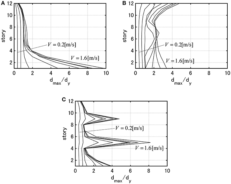
Figure 5 shows the maximum interstory drift distributions by DIP. The velocity level is increased from V = 0.2 [m/s] to V = 1.6 [m/s] by 0.2 [m/s].
Since the input velocity level of the critical double impulse influences greatly the maximum interstory drift and the optimal damper placement, its determination appears very important. The determination process of the input velocity level of the critical double impulse is explained in the next.
(1) Specify the maximum interstory drift of the initial design model (bare model).
(2) Conduct DIP for the initial design model. Find the velocity level V for which the maximum interstory drift of the initial design model exceeds the specified value for the first time. Conduct DIP also for larger values of the velocity level V.
(3) Draw the maximum interstory drift distributions by DIP as shown in Figure 5. Realize how easily the plastic deformation is concentrated to a special location. Based on these results, determine the input velocity level of the critical double impulse so that the maximum interstory drift exceeds the specified value.
Model 3 is treated as an example for determining the input level. The double of the yield interstory drift is taken as the specified target value of the maximum interstory drift. Then it is found that over 0.6 [m/s] is necessary. Although the input velocity level should be chosen for each structural model, V = 0.84 [m/s] and 1.23 [m/s] are employed in the following section.
Numerical Examples
Examples for Problem 1 Using Algorithm 1
Consider first some examples for Problem 1. The amplitudes of the critical double impulses have been determined from the results for DIP explained in Section Dynamic Pushover Analysis Under Amplified Critical Double Impulse.
Figure 6 shows the distribution of added damping coefficients, max (dmax,i/dy) with respect to step number and the distribution of dmax,i/dy under the critical double impulses with V = 0.84 [m/s] and V = 1.23 [m/s] for Model 1. The condition dtarget,i = dy (for all i) is employed here.
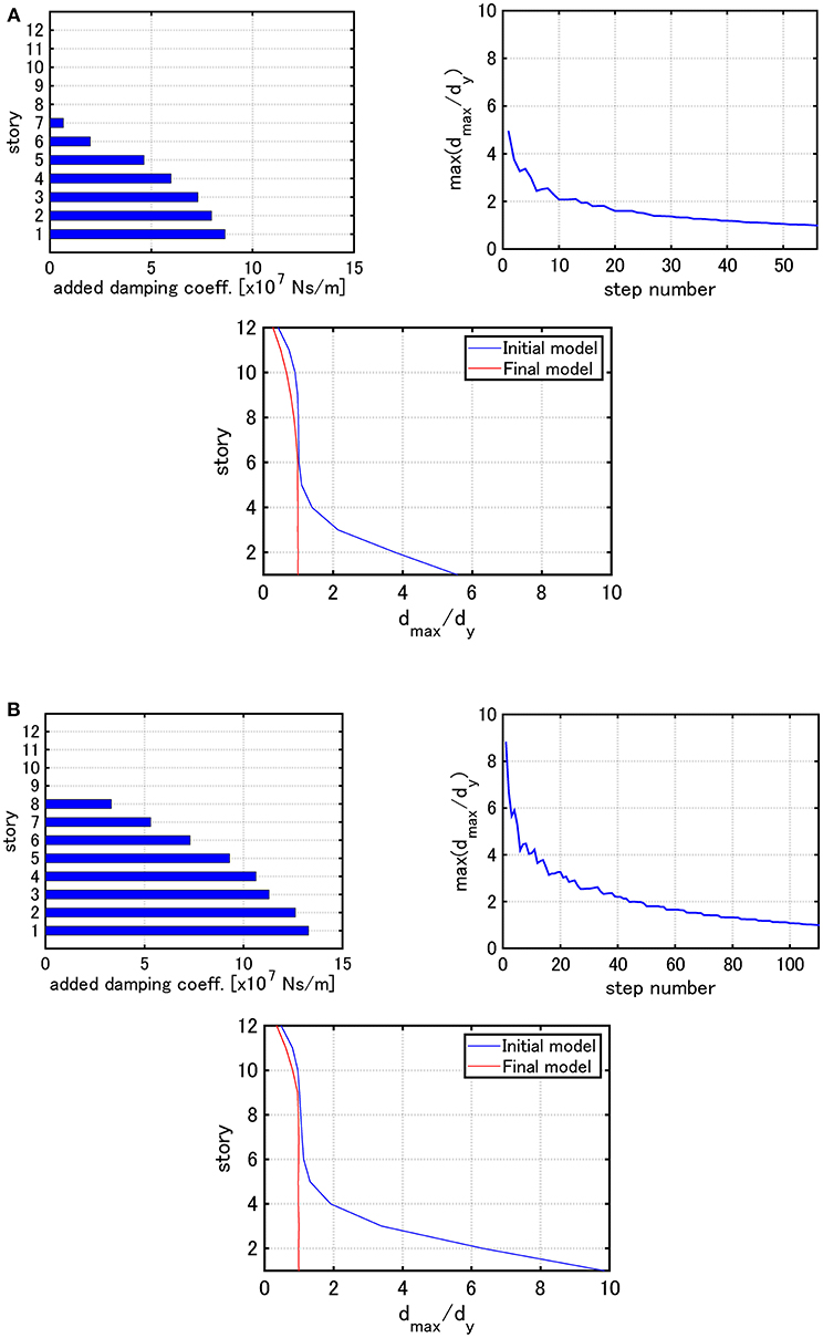
Figure 6. Distribution of added damping coefficients, max (dmax,i/dy) with respect to step number and the distribution of dmax,i/dy under the critical double impulse for Model 1 (Problem 1): (A) V = 0.84 [m/s], (B) V = 1.23 [m/s].
Figure 7 presents the similar figures for Model 2 and Figure 8 illustrates the similar figures for Model 3.
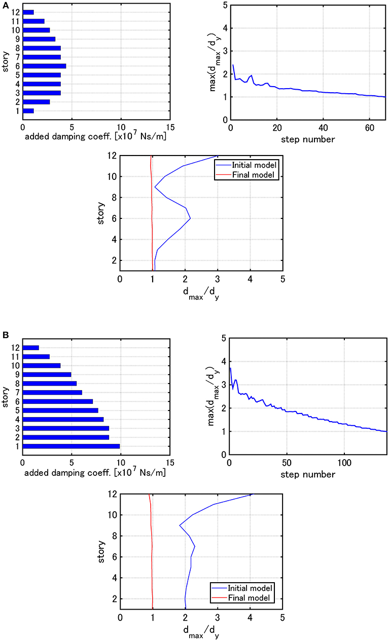
Figure 7. Distribution of added damping coefficients, max (dmax,i/dy) with respect to step number and the distribution of dmax,i/dy under the critical double impulse for Model 2 (Problem 1): (A) V = 0.84 [m/s], (B) V = 1.23 [m/s].
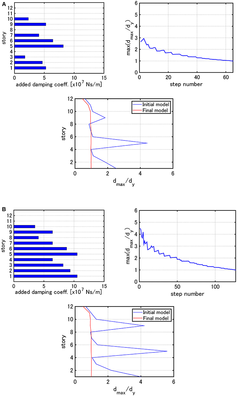
Figure 8. Distribution of added damping coefficients, max (dmax,i/dy) with respect to step number and the distribution of dmax,i/dy under the critical double impulse for Model 3 (Problem 1): (A) V = 0.84 [m/s], (B) V = 1.23 [m/s].
It can be observed from Figures 6–8 that, as the input velocity level is increased, the ratios of damping coefficients of added dampers along height change and their allocation becomes smooth in the wide height range. This is because, as the input level becomes larger, the number of stories experiencing plastic deformation becomes larger. Secondly, the maximum interstory drift distribution in the final model becomes almost uniform by Algorithm 1. Furthermore, it is understood that the increase of max(dmax,i/dy) in the damper allocation process is allowed.
For Model 3, it can be observed that the dampers are not allocated in the 4th and 8th stories for the input level V = 0.84 [m/s], but those are allocated for the input level V = 1.23 [m/s]. However, the maximum interstory drifts in those stories are smaller than the elastic limit in the initial stage. This means that Algorithm 1 acts first so that the dampers are allocated to the 1, 5, 9 th stories experiencing large plastic deformation. This process helps the energy required for deformation distribute to the neighboring stories. As a result, among the stories neighboring to the 5, 9th stories, the deformations in the 6, 10th stories with relatively small stiffness becomes larger. Since the 4, 8th stories with relatively large stiffness go into the plastic range for the input level of V = 1.23 [m/s], the dampers are allocated so as to strengthen the model. A similar observation may be possible also for Model 1 and 2.
It may be concluded that Algorithm 1 is apt to allocate added dampers in a concentrated manner to the stories where the plastic deformation develops fast, then to allocate additional ones to rather weak stories after the strengthening is completed.
Examples for Problem 2 Using Algorithm 2
Consider next some examples for Problem 2. The parameter specification is given here.
Figure 9 shows the distribution of added damping coefficients, ∑dmax,i/dy with respect to step number and the distribution of dmax,i/dy under the critical double impulses with V = 0.84 [m/s] and V = 1.23 [m/s] for Model 1. The distributions for the elastic limit are also shown for reference (max(dmax,i/dy) = 1).
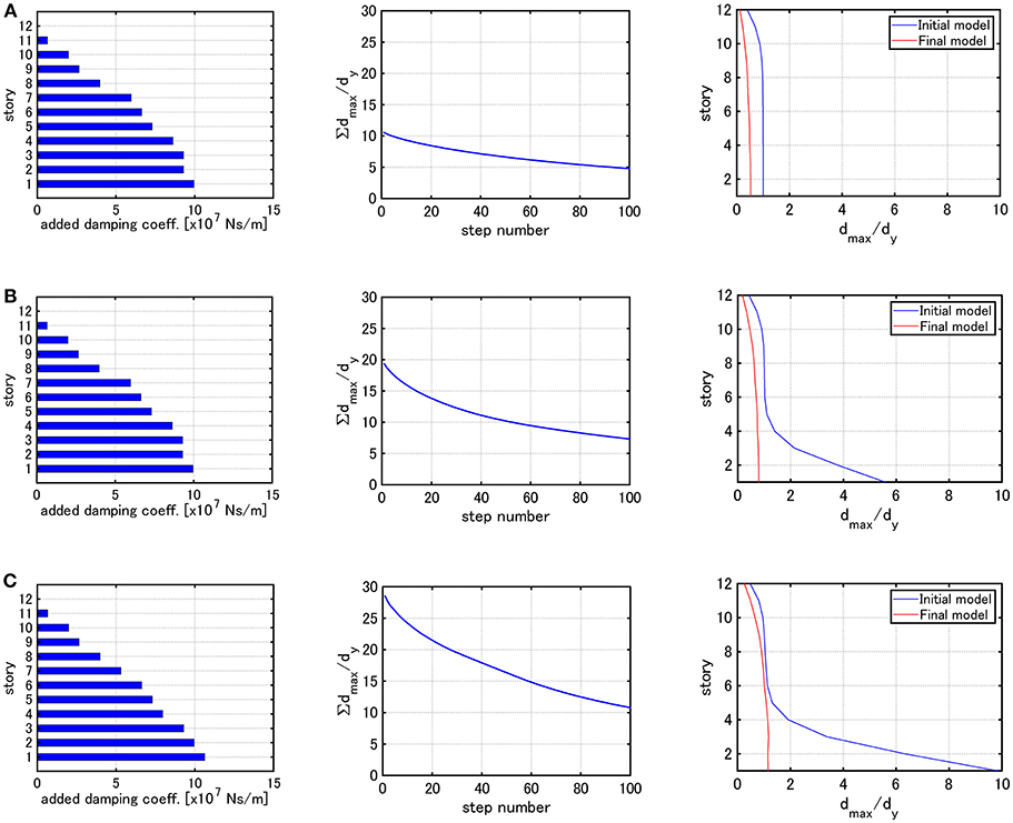
Figure 9. Distribution of added damping coefficients, ∑dmax,i/dy with respect to step number and the distribution of dmax,i/dy under the critical double impulse for Model 1 (Problem 2): (A) Elastic limit, (B) V = 0.84 [m/s], (C) V = 1.23 [m/s].
Figure 10 presents the similar figures for Model 2 and Figure 11 illustrates the similar figures for Model 3.
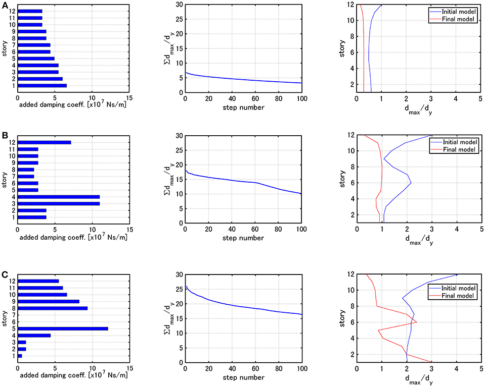
Figure 10. Distribution of added damping coefficients, ∑dmax,i/dy with respect to step number and the distribution of dmax,i/dy under the critical double impulse for Model 2 (Problem 2): (A) Elastic limit, (B) V = 0.84 [m/s], (C) V = 1.23 [m/s].
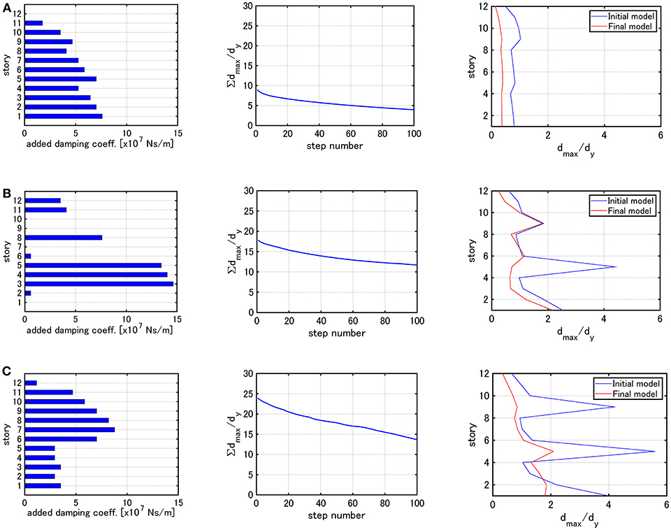
Figure 11. Distribution of added damping coefficients, ∑dmax,i/dy with respect to step number and the distribution of dmax,i/dy under the critical double impulse for Model 3 (Problem 2): (A) Elastic limit, (B) V = 0.84 [m/s], (C) V = 1.23 [m/s].
It can be observed that, when the elastic limit is employed for determining the input velocity level, the dampers are allocated so that the maximum interstory drifts become almost uniform for all models (Model 1–3). For Model 1, the dampers are allocated so that the maximum interstory drifts become almost uniform regardless of the input velocity level. On the other hand, for Models 2 and 3, the damper distributions are different depending on the input velocity level. Furthermore, for Models 2 and 3, the maximum interstory drifts in specific stories do not change between the initial model and the final model. This means that, since Algorithm 2 is aimed at finding the optimal damper allocation by using the steepest direction, it does not provide better damper allocation from the viewpoint of uniform reduction of the maximum interstory drifts in all stories.
Examples for Mixed Problem (Problem 3) of Problem 1 and 2 Using Algorithm 3
Examples for Mixed Problem (Problem 3) of Problem 1 and 2 using Algorithm 3 are presented here. The parameter specification by is used for V = 0.84 [m/s] and the parameter specification by is used for V = 1.23 [m/s].
Figure 12 shows the distribution of added damping coefficients, ∑dmax,i/dy with respect to step number and the distribution of dmax,i/dy under the critical double impulses with V = 0.84 [m/s] and V = 1.23 [m/s] for Model 1.
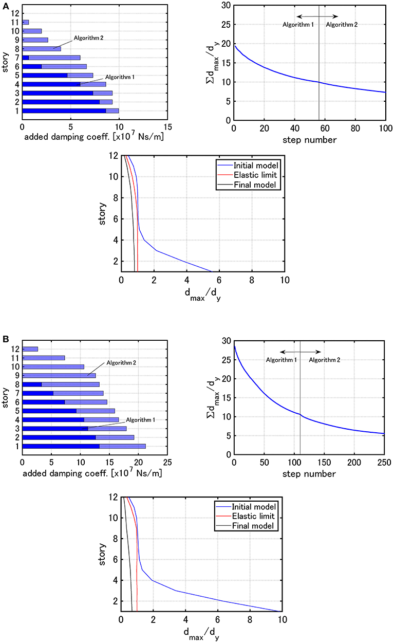
Figure 12. Distribution of added damping coefficients, ∑dmax,i/dy with respect to step number and the distribution of dmax,i/dy under the critical double impulse for Model 1 (Problem 3): (A) V = 0.84 [m/s], (B) V = 1.23 [m/s].
Figure 13 presents the similar figures for Model 2 and Figure 14 illustrates the similar figures for Model 3.
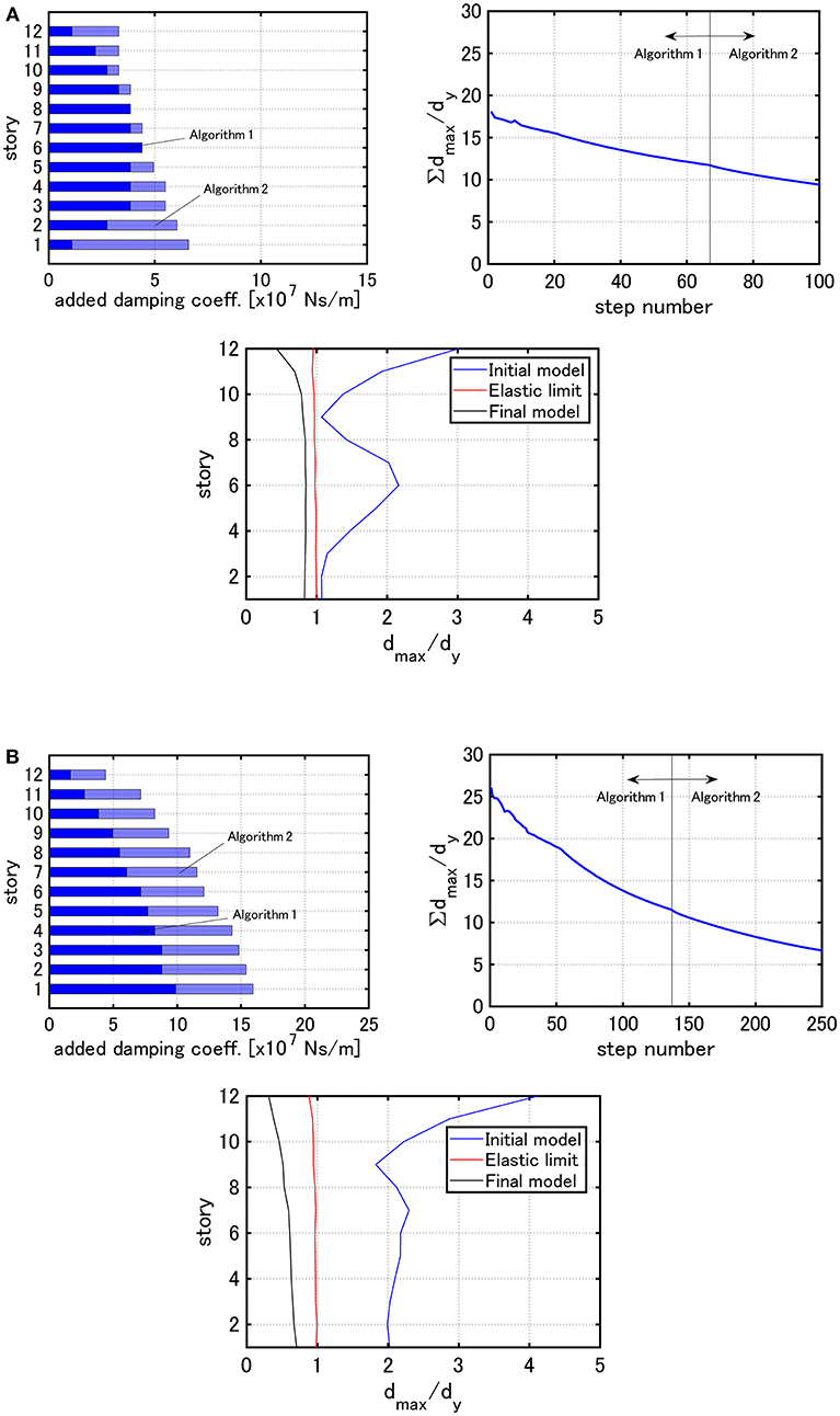
Figure 13. Distribution of added damping coefficients, ∑dmax,i/dy with respect to step number and the distribution of dmax,i/dy under the critical double impulse for Model 2 (Problem 3): (A) V = 0.84 [m/s], (B) V = 1.23 [m/s].
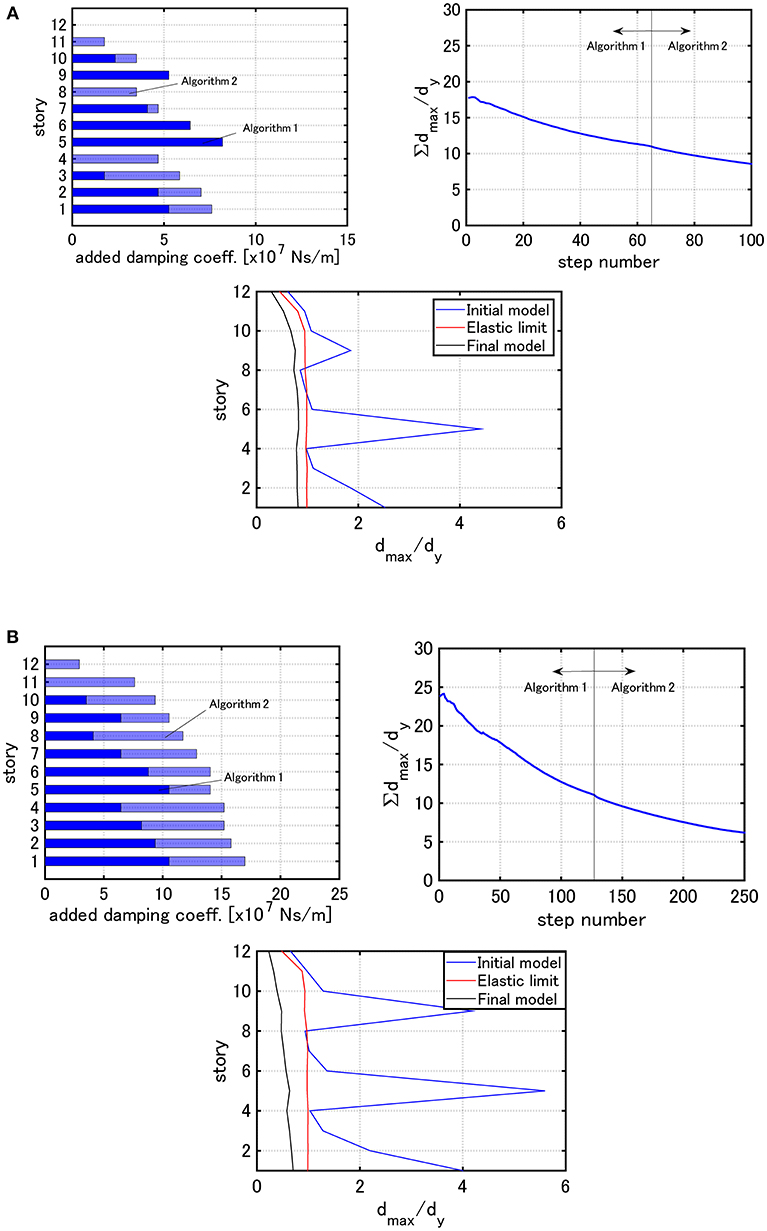
Figure 14. Distribution of added damping coefficients, ∑dmax,i/dy with respect to step number and the distribution of dmax,i/dy under the critical double impulse for Model 3 (Problem 3): (A) V = 0.84 [m/s], (B) V = 1.23 [m/s].
It can be observed that, while the analysis in the elastic range is not easy by Algorithm 1 for Problem 1 owing to the inability to set the total damper quantity and the maximum interstory drift distribution of the final model obtained by Algorithm 2 for Problem 2 is unstable (not uniform) depending on the model, a stable damper allocation is possible by Algorithm 3 for Problem 3 regardless of the input velocity level of the critical double impulse and the final maximum interstory drift distributions are apt to become uniform. It may be said that Algorithm 3 enables the procedure to guarantee the minimum performance by using a small amount of added dampers and to reduce the structural response globally by using the additional amount of added dampers.
Conclusions
A new method for optimal viscous damper placement has been proposed for elastic-plastic MDOF structures subjected to the critical double impulse as a representative of near-fault ground motions. The main conclusions can be summarized as follows.
(1) The proposed method consists of two phases: (i) Rapid reduction of the overflowed maximum inelastic interstory drift by the effective concentrated insertion of viscous dampers, (ii) Effective damper allocation using a stable objective function sensitivity analysis. The sensitivity analysis employs the time-history response analysis for the critical double impulse and the finite difference analysis for damping coefficients.
(2) The adoption of the critical timing of the second impulse based on the criterion on the maximum input energy enables an efficient analysis of optimal damper placement. This criterion greatly reduces the analysis load for finding the critical timing requiring repetition in conventional methods.
(3) A new concept of double impulse pushover (DIP) was proposed for determining the appropriate input velocity level of the critical double impulse.
(4) The critical double impulse enables an efficient analysis of optimal damper placement for near-fault ground motions.
(5) The proposed method is useful for broad-type building structures with various stiffness distributions.
Author Contributions
HA formulated the problem, conducted the computation, and wrote the manuscript. IT supervised the research and wrote the manuscript.
Funding
Part of the present work is supported by the Grant-in-Aid for Scientific Research (KAKENHI) of Japan Society for the Promotion of Science (No.17K18922, 18H01584) and Sumitomo Rubber Industries, Co. This support is greatly appreciated.
Conflict of Interest Statement
The authors declare that the research was conducted in the absence of any commercial or financial relationships that could be construed as a potential conflict of interest.
Supplementary Material
The Supplementary Material for this article can be found online at: https://www.frontiersin.org/articles/10.3389/fbuil.2019.00020/full#supplementary-material
References
Abrahamson, N., Ashford, S., Elgamal, A., Kramer, S., Seible, F., and Somerville, P. (1998). 1st PEER Workshop on Characterization of Special Source Effects. San Diego, CA: Pacific Earthquake Engineering Research Center, University of California.
Adachi, F., Yoshitomi, S., Tsuji, M., and Takewaki, I. (2013). Nonlinear optimal oil damper design in seismically controlled multi-story building frame. Soil Dyn. Earthquake Eng. 44, 1–13. doi: 10.1016/j.soildyn.2012.08.010
Akehashi, H., Kojima, K., Fujita, K., and Takewaki, I. (2018b). Critical response of nonlinear base-isolated building considering soil-structure interaction under double impulse as substitute for near-fault ground motion. Front. Built. Environ. 4:34. doi: 10.3389/fbuil.2018.00034
Akehashi, H., Kojima, K., and Takewaki, I. (2018a). Critical response of SDOF damped bilinear hysteretic system under double impulse as substitute for near-fault ground motion. Front. Built Environ. 4:5. doi: 10.3389/fbuil.2018.00005
Attard, T. L. (2007). Controlling all interstory displacements in highly nonlinear steel buildings using optimal viscous damping. J. Struct. Eng. ASCE 133, 1331–1340. doi: 10.1061/(ASCE)0733-9445(2007)133:9(1331)
Aydin, E., Boduroglub, M. H., and Guney, D. (2007). Optimal damper distribution for seismic rehabilitation of planar building structures. Eng. Struct. 29, 176–185. doi: 10.1016/j.engstruct.2006.04.016
Bertero, V. V., Mahin, S. A., and Herrera, R. A. (1978). Aseismic design implications of near-fault San Fernando earthquake records. Earthquake Eng. Struct. Dyn. 6, 31–42. doi: 10.1002/eqe.4290060105
Domenico, D. D., Ricciardi, G., and Takewaki, I. (2019). Design strategies of viscous dampers for seismic protection of building structures: a review. Soil Dyn. Earthquake Eng. 118, 144–165. doi: 10.1016/j.soildyn.2018.12.024
Garcia, D. L. (2001). A simple method for the design of optimal damper configurations in MDOF structures. Earthquake Spectra 17, 387–398. doi: 10.1193/1.1586180
Hatzigeorgiou, G. D., and Pnevmatikos, N. G. (2014). Maximum damping forces for structures with viscous dampers under near-source earthquakes. Eng. Struct. 68, 1–13. doi: 10.1016/j.engstruct.2014.02.036
Kalkan, E., and Kunnath, S. K. (2006). Effects of fling step and forward directivity on seismic response of buildings, Earthquake Spectra 22, 367–390. doi: 10.1193/1.2192560
Kojima, K., Saotome, Y., and Takewaki, I. (2017). Critical earthquake response of a SDOF elastic-perfectly plastic model with viscous damping under double impulse as a substitute of near-fault ground motion. J. Struct. Construct. Eng. 735, 643–652. doi: 10.1002/2475-8876.10019
Kojima, K., and Takewaki, I. (2015). Critical earthquake response of elastic-plastic structures under near-fault ground motions (Part 1: Fling-step input). Front. Built Environ. 1:12. doi: 10.3389/fbuil.2015.00012
Kojima, K., and Takewaki, I. (2016). Closed-form critical earthquake response of elastic-plastic structures with bilinear hysteresis under near-fault ground motions. J. Struct. Construct. Eng. 726, 1209–1219. doi: 10.3130/aijs.81.1209
Lavan, O., Cimellaro, G. P., and Reinhorn, A. M. (2008). Noniterative optimization procedure for seismic weakening and damping of inelastic structures. J. Struct. Eng. ASCE 134, 1638–1648. doi: 10.1061/(ASCE)0733-9445(2008)134:10(1638)
Lavan, O., and Levy, R. (2005). Optimal design of supplemental viscous dampers for irregular shear-frames in the presence of yielding. Earthquake Eng. Struct. Dyn. 34, 889–907 doi: 10.1002/eqe.458
Lavan, O., and Levy, R. (2006). Optimal design of supplemental viscous dampers for linear framed structures. Earthquake Eng. Struct. Dyn. 35, 337–356. doi: 10.1002/eqe.524
Mavroeidis, G. P., and Papageorgiou, A. S. (2003). A mathematical representation of near-fault ground motions. Bull. Seism. Soc. Am. 93, 1099–1131. doi: 10.1785/0120020100
Murakami, Y., Noshi, K., Fujita, K., Tsuji, M., and Takewaki, I. (2013). Simultaneous optimal damper placement using oil, hysteretic and inertial mass dampers. Earthquakes Struct. 5, 261–276. doi: 10.12989/eas.2013.5.3.261
Ozturk, B. (2003). Seismic Drift Response of Building Structures in Seismically Active and Near-Fault Regions. PhD Thesis. Purdue University.
Papagiannopoulos, G. A., Hatzigeorgiou, G. D., and Pnevmatikos, N. G. (2018). “A seismic retrofit method for steel frames with viscous dampers,” in Proc. of the 16th European Conference on Earthquake Engineering (Thessaloniki).
Pollini, N., Lavan, O., and Amir, O. (2017). Minimum-cost optimization of nonlinear fluid viscous dampers and their supporting members for seismic retrofitting. Earthquake Eng. Struct. Dyn. 46, 1941–1961. doi: 10.1002/eqe.2888
Saotome, Y., Kojima, K., and Takewaki, I. (2018). Earthquake response of 2DOF elastic-perfectly plastic model under multiple impulse as substitute for long-duration earthquake ground motions. Front. Built Environ. 4:81. doi: 10.3389/fbuil.2018.00081
Shiomi, T., Fujita, K., Tsuji, M., and Takewaki, I. (2018). Dual hysteretic damper system effective for broader class of earthquake ground motions. Int. J. Earthquake Impact Eng. 2, 175–202. doi: 10.1504/IJEIE.2018.093391
Silvestri, S., and Trombetti, T. (2007). Physical and numerical approaches for the optimal insertion of seismic viscous dampers in shear-type structures. J. Earthquake Eng. 11, 787–828. doi: 10.1080/13632460601034155
Singh, M. P., and Moreschi, L. M. (2001). Optimal seismic response control with dampers. Earthquake Eng. Struct. Dyn. 30, 553–572. doi: 10.1002/eqe.23
Takewaki, I. (1997). Optimal damper placement for minimum transfer functions. Earthquake Eng. Struct. Dyn. 26, 1113–1124.
Takewaki, I. (2009). Building Control With Passive Dampers: -Optimal Performance-based Design for Earthquakes. Singapore: John Wiley & Sons Ltd.
Takewaki, I., Yoshitomi, S., Uetani, K., and Tsuji, M. (1999). Non-monotonic optimal damper placement via steepest direction search. Earthquake Eng. Struct. Dyn. 28, 655–670.
Taniguchi, R., Kojima, K., and Takewaki, I. (2016). Critical response of 2DOF elastic-plastic building structures under double impulse as substitute of near-fault ground motion. Front. Built Environ. 2:2. doi: 10.3389/fbuil.2016.00002
Tsuji, M., and Nakamura, T. (1996). Optimum viscous dampers for stiffness design of shear buildings. J. Struct. Design Tall Build. 5, 217–234.
Uetani, K., Tsuji, M., and Takewaki, I. (2003). Application of optimum design method to practical building frames with viscous dampers and hysteretic dampers. Eng. Struct. 25, 579–592. doi: 10.1016/S0141-0296(02)00168-2
Vamvatsikos, D., and Cornell, C. A. (2001). Incremental dynamic analysis. Earthquake Eng. Struct. Dyn. 31, 491–514. doi: 10.1002/eqe.141
Whittle, J. K., Williams, M. S., Karavasilis, T. L., and Blakeborough, A. (2012). A comparison of viscous damper placement methods for improving seismic building design. J. Earthquake Eng. 16, 540–560. doi: 10.1080/13632469.2011.653864
Keywords: earthquake response, critical excitation, critical response, elastic-plastic response, viscous damping, resonance, double impulse, multi-degree-of-freedom model
Citation: Akehashi H and Takewaki I (2019) Optimal Viscous Damper Placement for Elastic-Plastic MDOF Structures Under Critical Double Impulse. Front. Built Environ. 5:20. doi: 10.3389/fbuil.2019.00020
Received: 18 January 2019; Accepted: 12 February 2019;
Published: 07 March 2019.
Edited by:
Nikos D. Lagaros, National Technical University of Athens, GreeceReviewed by:
Nikos Pnevmatikos, University of West Attica, GreeceBaki Ozturk, Hacettepe University, Turkey
Copyright © 2019 Akehashi and Takewaki. This is an open-access article distributed under the terms of the Creative Commons Attribution License (CC BY). The use, distribution or reproduction in other forums is permitted, provided the original author(s) and the copyright owner(s) are credited and that the original publication in this journal is cited, in accordance with accepted academic practice. No use, distribution or reproduction is permitted which does not comply with these terms.
*Correspondence: Izuru Takewaki, dGFrZXdha2lAYXJjaGkua3lvdG8tdS5hYy5qcA==
 Hiroki Akehashi
 Izuru Takewaki