 Sanjay Shrawan Nimbalkar
 Piyush Punetha
 Sudip Basack
 Mehdi Mirzababaei
- 1Faculty of Engineering and Information Technology, School of Civil and Environmental Engineering, University of Technology Sydney, Ultimo, NSW, Australia
- 2Geotechnical Engineering Division, CSIR-Central Building Research Institute, Roorkee, India
- 3Department of Civil Engineering, Kaziranga University Jorhat, Jorhat, India
- 4School of Engineering and Technology, Central Queensland University, Melbourne, VIC, Australia
Pile foundations supporting large structures (such as high-rise buildings, oil drilling platforms, bridges etc). are often subjected to eccentric lateral load (in addition to the vertical loads) due to the action of wind, waves, high speed traffic, and ship impacts etc. The eccentric lateral load, which is usually cyclic (repetitive) in nature, induces torsion in the pile foundation. This paper presents a numerical model based on boundary element approach to study the performance of a single pile subjected to the torsional cyclic load. The model is initially validated by comparing it with the experimental data available from the literature. Thereafter, the model has been utilized to conduct a parametric study to understand the influence of the torsional cyclic loading parameters on the axial pile capacity. The results indicated that the model is able to capture the degradation in the axial pile capacity due to the torsional cyclic loading with a reasonable accuracy. Moreover, the parametric study showed that the frequency, amplitude and number of cycles play a significant role in the torsional cyclic response of the pile. The present study is essential for the development of design guidelines for pile foundations subjected to torsional cyclic load.
Introduction
The construction of large structures such as high-rise buildings, oil drilling platforms, electrical transmission towers, wind turbines, bridges, and railway embankments over a soft compressible clay poses a serious challenge to the design engineers. Therefore, a cost-effective foundation system with an acceptable degree of safety is required and consequently, these structures are usually supported by pile foundations. These piles are often subjected to cyclic (repetitive) lateral loads in addition to the vertical loads, during their service life due to wind, sea waves, high speed train traffic and ship impacts etc. (Arshad and O'Kelly, 2016; Haiderali and Madabhushi, 2016). The cyclic lateral load often acts eccentrically and generates cyclic torsion on the pile foundation (Barker and Puckett, 1997). The inadequate design of these piles against the cyclic torsional loading may affect the safety and serviceability of the foundation, leading to disastrous consequences (Vickery, 1979; Barker and Puckett, 1997). Moreover, in case of foundations supporting offshore platforms, the amplitude (magnitude) of the cyclic torsional load is high and is usually accompanied with low frequency vibrations, while the reverse is true for onshore structures including railways (Nimbalkar and Indraratna, 2016).
The cyclic load initiates the reversal of soil-pile interface shear stress, thus producing a progressive deterioration in strength and stiffness of the surrounding soil and consequently, pile-soil interactive performance undergoes significant degradation (Basack, 2015). Such degradation may reduce the load carrying capacity of the pile and increase the pile head displacement (settlement). The primary reason for such degradation is the gradual reorientation and rearrangement of the soil particles adjacent to the pile-soil interface. The other reasons include the generation of excess pore water pressure and the development of irrecoverable plastic deformation of soil adjacent to the pile soil interface (Basack and Dey, 2012).
Several theoretical, laboratory and field-based investigations on the pile foundations subjected to vertical and lateral cyclic loads have been conducted in the past (El Naggar et al., 1998; Cavey et al., 2000; Taciroglu et al., 2006; Basack, 2010a; Jardine and Standing, 2012). Moreover, the behavior of pile subjected to static torsion has been investigated by several researchers (e.g., Stoll, 1972; Poulos, 1975; Kong and Zhang, 2008; Misra et al., 2014; Chen et al., 2016). However, the studies pertaining to the influence of torsional cyclic load on the behavior of pile foundation are rather limited. It has been found that the torsional load can significantly influence the load carrying capacity of the pile. The skin friction mobilized due to the axial load interacts with the circumferential pile-soil interface shear stress (induced due to the torsional load) and consequently, the axial pile capacity decreases and the axial displacement increases (Basack and Sen, 2014a). Therefore, the investigation of the behavior of pile subjected to cyclic torsional loading becomes imperative for the safe design and satisfactory long-term performance of the pile foundations supporting the large offshore or onshore structures.
The behavior of pile foundation subjected to monotonic and cyclic axial loading can be investigated by using several numerical and analytical techniques available in the literature. These include the dynamic response analysis, cyclic stability analysis, finite element and boundary element analysis etc. to name a few (Poulos, 1982, 1988; Bea, 1992; Basack and Dey, 2012; Fatahi et al., 2014). In the present paper, a novel numerical methodology based on boundary element modeling (BEM) is proposed to capture the response of a single, vertical, floating pile subjected to combined axial, and torsional cyclic loads. The non-linear stress-strain response of the soil is incorporated in the model by using a hyperbolic function. Moreover, the constitutive behavior of the pile material is assumed to be elastic-perfectly plastic. The effect of progressive degradation of soil strength and stiffness under interface shear stress reversal (or simply cyclic loading) has been incorporated by using an exponential correlation and a semi-logarithmic rate function. The analysis could also have been conducted using finite element method which might have required the use of three-dimensional meshes to represent the pile, the interface and the surrounding soil mass (Lebeau, 2008; Kim and Jeong, 2011). However, an enormous computational effort is required in finite element analysis to incorporate the non-linear stress-strain response of soil and progressive slippage at the interface. Moreover, the studies conducted by Poulos (1989), Basile (2010), and Fattah et al. (2012) underlines several advantages of the use of boundary element method as an alternative of FEM to solve the pile-soil interaction problems.
The paper is presented in the following sequence: first, a model is formulated using BEM approach followed by its validation by comparing the BEM computed results with the available field data. Such comparison indicates reasonable accuracy of the proposed numerical solutions. Thereafter, a prototype parametric study is conducted using the developed model to analyse the influence of cyclic loading parameters on the soil-pile interactive performance. Finally, the normalized soil-pile interface shear stress profiles (predict using the proposed solution) are presented to show the distribution of stresses along the length of pile for static and post-cyclic condition.
Numerical Modeling: Mathematical Formulations
Problem Definition
Figure 1A shows a single, vertical, floating pile of diameter D with embedded depth of L, subjected to an axial static load of Vt and a two way symmetrical cyclic torsional load (given by Equation 1):
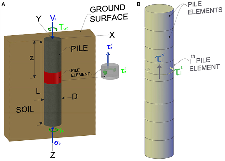
Figure 1. Numerical modeling: (A), Idealized problem (B), BEM discretization of the pile.
Where, and f are the amplitude and frequency of the cyclic torsional load, respectively. The imposed axial and torsional loads induce the stresses τb and σb at the base of the pile, and shear stresses and at the soil-pile interface along the length of the pile in the horizontal and vertical directions, respectively (see Figure 1A). The stresses and σbare primarily induced due to the axial load and are static, whereas, the stresses and τb are induced due to the torsional load and are cyclic. The primary aim of this study is to evaluate these unknown interface shear stress components and subsequently, determine the axial pile capacity after completion of a certain number of load cycles (N).
The pile material in the present study has been idealized as elastic-perfectly plastic. The stress-strain behavior of the soil in shear is assumed to be non-linear up to the peak shear stress (τu), followed by a perfectly plastic post-peak response (Basack and Sen, 2014a). The non-linear pre-peak behavior has been represented using a hyperbolic equation (Equation 2) with an initial tangent modulus of Gi and a reduction factor of Rf (Duncan and Chang, 1970). The value of the reduction factor, Rf usually varies in the range of 0.8–1.0 (Randolph, 2003).
Where, τ andγ are the shear stress and shear strain, respectively. The post peak response can be mathematically represented as:
Boundary Element Modeling
The pile-soil interaction in the present study has been analyzed using the Boundary Element Modeling (BEM) following the methodology of (Basack and Sen, 2014a,b). The pile is longitudinally discretized into n cylindrical elements of equal height (thickness), δ (see Figure 1B). The unknown pile-soil interface shear stress components in the horizontal and vertical directions in the ith element have been denoted as and , respectively. Moreover, the displacement components at the central nodal plane (i.e., the central plane of each pile element) have been denoted as ρi and θi corresponding to the vertical and torsional modes, respectively.
Initially, the analysis has been performed for static loading with subsequent extension for the cyclic loading by using appropriate parameters for simulating the degradation of soil strength and stiffness (under cyclic loading), and the influence of the cyclic loading parameters. First, the static axial and torsional loadings are analyzed separately, followed by a coupled analysis to arrive at specific solutions. The governing differential equations for the static torsion (Equation 4) and static axial load (Equation 5) are given as (Basack and Sen, 2014a,b):
Where, θ is the angle of twist; ρ is the vertical displacement; z is the depth; Jp is the polar moment of inertia of pile cross section; Gp is the modulus of rigidity of the pile; Ep is the Young's modulus of the pile; is the unit weight of the pile. For static torsion, the governing differential equation is solved using the finite difference technique by developing correlations between the twist angle (θ) and some functions of D, δ, , Jp, Gp and pile head torque (Tt). The correlations are then compiled together (in a matrix form) and the resultant matrix is given by:
Where, [CM] is a coefficient matrix of order (n+1) x (n+1), {θ} is a column vector of order (n+1) x 1 and {a} is augment vector of order (n+1) x 1. The elements of the coefficient matrix, column vector, and augment vector can be found in Basack and Sen (2014a). There are two sets of unknown quantities in Equation 6, namely θi and . Therefore, an initial no-slip condition is assumed and a correlation between θi and (given by Randolph, 1981) is used (Equation 7) to reduce the number of unknown quantities in Equation (6).
Where, Gs is the soil secant modulus. Using the provided correlation (Equation 7), the Equation (6) is modified to:
Where, [DM] and {b} are coefficient matrix and augment vector, respectively and the elements of these matrices/vectors are functions of D, δ, Jp, Gs, Gp, and Tt. The initial values of the unknown horizontal torsional interface shear stress ( ) are computed using Equation (8). The values of for each element are then compared with the limiting values of interface shear stress (τu) for each element. The elements are assumed to have slipped if the value of exceeds theτu. The initial value of for slipped elements is replaced by τu and appropriate adjustments are made to the initial values of Gs to incorporate the soil non-linearity. The entire computation procedure is then repeated for the rest of the non-slipped elements until the desired convergence is achieved.
The governing differential equation for the static axial load is solved by using a similar procedure as described above i.e., by utilizing the finite difference technique and a correlation between ρ and given by Randolph and Wroth (1978) (for no-slip condition). After evaluating the unknown parameters and from the separate analyses for axial and torsion loads, a coupled analysis is conducted by evaluating the resultant interface shear stress for each element, through vector addition of and (see Figure 2), given by:
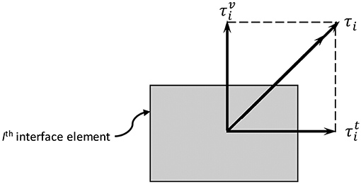
Figure 2. Addition of interface stresses in coupled analysis.
The resultant interface shear stress is then compared with the ultimate shear stress and the values of are recomputed (or adjusted). The procedure is repeated until the desired convergence is achieved. Finally, the values of twist angles are computed for each element using Equation 6. The detailed formulations for the analysis of static load are published elsewhere (Basack and Sen, 2014a,b; Basack and Nimbalkar, 2017).
The analysis for the torsional cyclic loading has been performed by using a quasi-static method with a peak torsion of , wherein the elemental stress and displacement components have been adjusted after the completion of a desired number of load cycles. The application of cyclic loading influences the strength and stiffness of the soil to a large extent. On one hand, the cyclic loading leads to the degradation of shear strength and stiffness of soil due to generation of excess pore-water pressure, generation of irrecoverable plastic strain in soil around the pile and rearrangement of soil particles in the vicinity of the pile (Poulos, 1981; Basack, 2015). However, on the contrary, the soil strength and stiffness increase with an increase in the loading rate (or frequency) (Poulos, 1989; Rodriguez and Alvarez, 2008). The following mathematical expression (Basack and Nimbalkar, 2017) addresses the combined effects of these two phenomena on the soil-pile interaction:
Where, is the nodal soil degradation factor, F is a non-dimensional rate factor, λr is a datum loading rate, γcis the peak nodal shear strain and A and B are the non-dimensional cyclic soil parameters. The soil degradation factor ( ) is defined as the ratio of the post cyclic to pre-cyclic values of soil strength and stiffness. The derivation and the details of the parameters for Equation 9 can be found elsewhere (Basack and Nimbalkar, 2017).
The post cyclic axial pile capacity is then evaluated, based on the degraded values of the shaft and end bearing resistance, using the following expression:
Where, is the post-cyclic axial pile capacity, δ is the height of pile elements, τui is the elemental ultimate soil strength, σbu is the ultimate base restraint and Wp is the self-weight of pile.
Finally, the pile degradation factor (Dp) is evaluated. It is defined as the ratio of the post-cyclic to static axial pile capacities (Equation 12):
where, is the ultimate static axial pile capacity. A user-friendly computer program PTCYC is written in FORTAN 90 language to conduct the desired computations. Figure 3 shows the flowchart of the computer program.
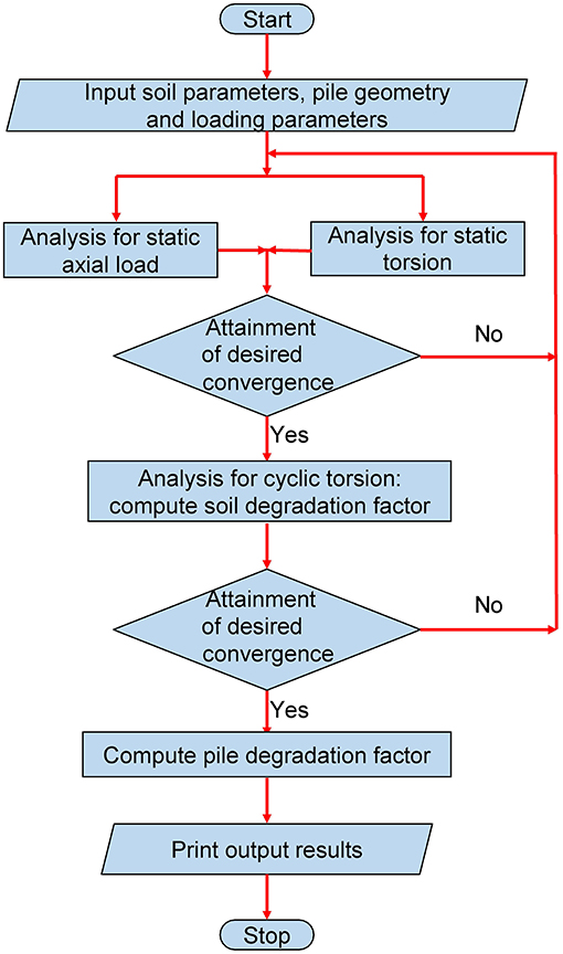
Figure 3. Flowchart for the FORTRAN program PTCYC.
Model Validation
The proposed solutions have been validated using the field test results available in literature. The field investigation on piles under composite torsional cyclic and axial static loading is extremely difficult and expensive. In absence of such research work, the authors have used the available laboratory and field test data to validate their numerical model. Stoll (1972) conducted a full-scale torsional load test on two concrete filled steel pipe piles embedded in a soil with a linearly increasing soil modulus. Guo and Randolph (1996) developed the analytical and numerical solutions for the torsional response of piles embedded in heterogeneous soil and validated the model with the field test results of Stoll (1972). The soil-pile interface shear stress profiles computed using the present model have been compared with the theoretical results of Guo and Randolph (1996) to validate the model (refer to Figure 4). From Figure 4, it can be observed that the results obtained using the present model are in good agreement with the solutions developed by Guo and Randolph (1996), with an average variation of about 21%.
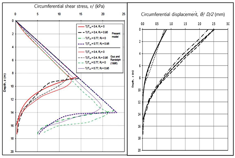
Figure 4. Comparison of the results computed using BEM with Guo and Randolph (1996).
Stuedlein et al. (2016) conducted a field study to evaluate the transfer of torsional load to soil along the soil-pile interface for two drilled concrete shafts in a site consisting of silty clay overlying a silty sand deposit. In addition to static torsion, cyclic torsion tests were also conducted on these shafts under one-way displacement-controlled mode with 20 displacement cycles at a frequency of 0.57 cycles per minute (cpm). The values of the resulting peak torsion evaluated from the present BEM computation have been compared with the field observations [for both the torsion test drilled shaft with production base (TDS) and torsion test drilled shaft with frictionless base (TDSFB)] of Stuedlein et al. (2016) (Figure 5). It is clear from this figure that the computed results are in acceptable agreement with the field test data with an average deviation of about 6%. Thus, the present numerical solutions are able to capture the soil-pile interaction under both static and cyclic torsional loads with an acceptable accuracy.
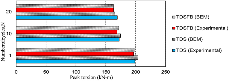
Figure 5. Comparison of the results computed using BEM with field test data of Stuedlein et al. (2016).
Parametric Studies: Analysis and Interpretation
The present boundary element model has been used to predict the response of a prototype vertical concrete floating pile embedded in soft clay subjected to a combined axial and cyclic torsional loading. Table 1 shows the properties of the soil and pile used (adopted from Basack, 2010a). The soil unit cohesion and the initial tangent shear modulus at the ground surface are 30 kPa and 300 MPa, respectively, which are assumed to increase linearly with depth at a rate of 3 kPa/m and 30 GPa/m, respectively. Moreover, the key input parameters to account for the strength and stiffness degradation (or improvement) under cyclic loading are: A = 4.5, B = 2.5, F = 0.1, λr = 0.11 mm/s. The axial load on the pile is assumed to be 0.4 times the axial pile capacity (for pure axial load condition) i.e., the load ratio (Vt/Vu0) is 0.4. The number of pile elements are fixed at 100 after conducting a sensitivity check (Basack and Nimbalkar, 2017).
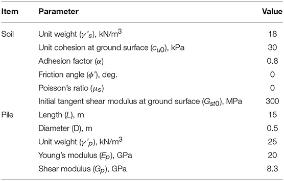
Table 1. Input parameters of soil and pile for the parametric study.
In the present study, the variation of the pile degradation factor (Dp) with cyclic loading parameters namely, number of cycles (N), frequency (f) and cyclic loading level (Lc) has been investigated. The cyclic loading level Lc is defined as the ratio of peak cyclic torsion to the static ultimate torsional pile capacity. The number of cycles, frequency and cyclic loading level have been varied in the range of 10–1,000 cycles, 5–30 c.p.m., and 15–30%, respectively. Moreover, the analysis has been conducted for two values of reduction factor (0.85 and 0.95) to investigate its influence on the soil-pile interactive performance.
Figures 6A–C show the variation of the Dp with N, f and Lc, respectively. It can be observed that the parameter Dp decreases with an increase in the number of loading cycles. However, the trend shows an asymptotically stabilizing tendency, i.e., the parameter Dp becomes almost constant after a certain number of loading cycles. This may be attributed to the exponential degradation of the soil strength and stiffness with N (Idriss et al., 1978). Moreover, Dp increases with an increase in the loading frequency. This is because the strength and stiffness of the soil increases logarithmically with f (Poulos, 1989). Furthermore, the pile degradation factor (Dp) decreases with an increase in Lc following a curvilinear pattern with an increasing slope. This observation is reasonable because an increase in the value of the torsional cyclic amplitude or cyclic loading level is likely to cause the failure of more number of elements (which is initiated by the rapid yielding of soil adjacent to the soil-pile interface) (Basack, 2010b). It must be noted that the reduction factor Rf shows insignificant effect on the soil-pile interactive performance.
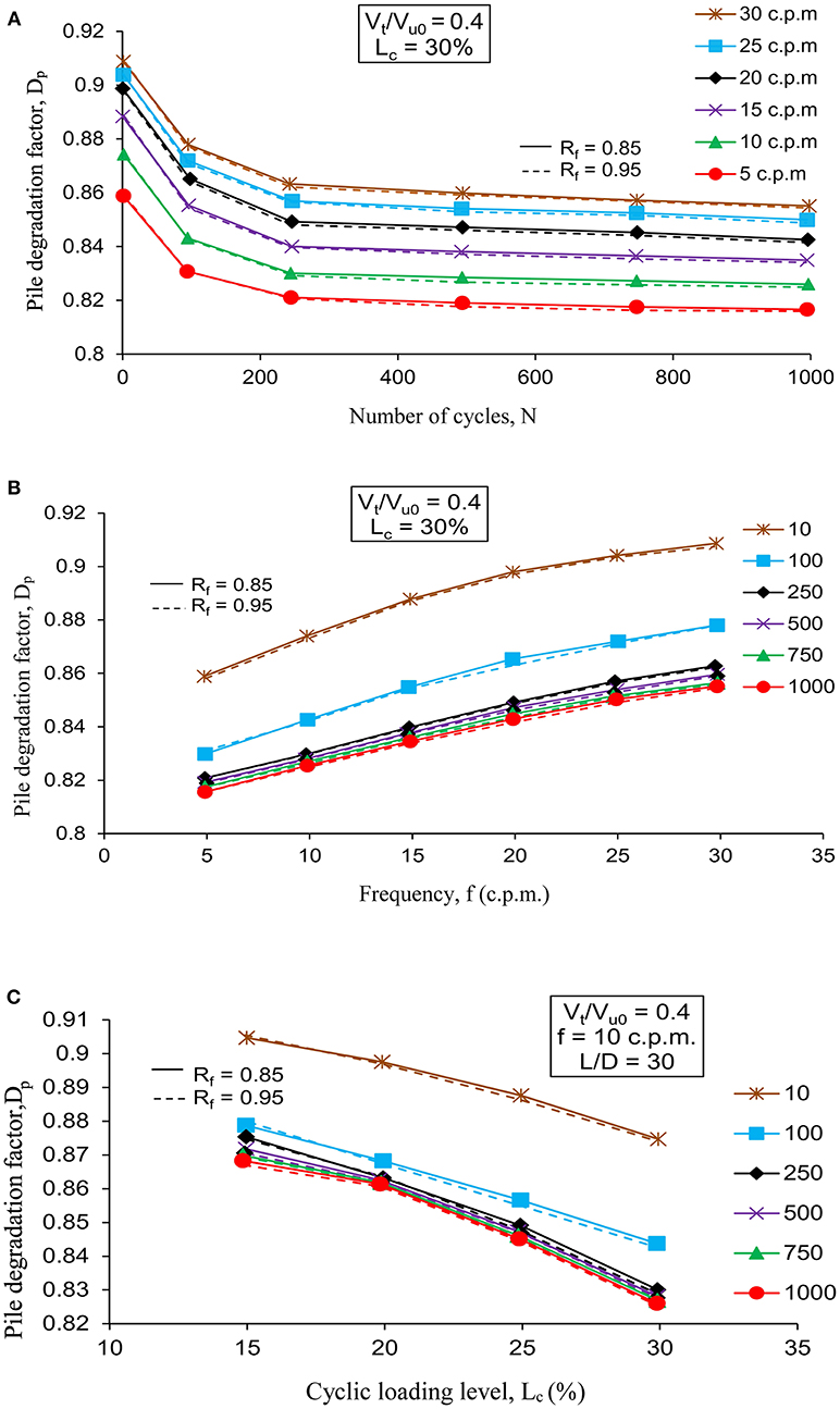
Figure 6. Variation of pile degradation factor with: (A), N (B), f (C), LC.
Figure 7 shows the profiles for the soil-pile interface shear stress (normalized by the product of unit cohesion and adhesion factor) for both static and post cyclic condition. It can be observed that the normalized shear stress attains a maximum value at the pile head and reduces to a minimum value at the base, in a curvilinear manner. It is interesting to note that the values of the post-cyclic shear stress have decreased as compared to the relevant value under static loading. Moreover, the percentage reduction is higher in the pile head (15%) as compared to the pile base (11%). The normalized shear stress values at the pile head and base are 0.74 and 0.45, respectively for the static condition while reduced to 0.63 and 0.4 after the application of the cyclic loading. This reduction is due to the degradation of the strength and stiffness of soil. Since, there is an overall reduction in the pile capacity, therefore, the influence of soil stiffness and strength degradation due to cyclic loading on the pile capacity is much higher as compared to the influence of loading frequency (which tends to enhance the soil strength and stiffness).
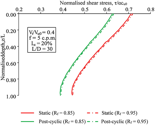
Figure 7. Normalized interface shear stress profile of pile for static and post-cyclic condition.
Practical Applications
The present study attempts to investigate the effect of the cyclic loading parameters namely, frequency, number of cycles and the amplitude, on the axial load carrying capacity of the pile foundation subjected to axial and torsional cyclic load. The results from the present study show that the axial loading capacity of the pile decreases with an increase in the number of loading cycles up to a particular number of cycles, beyond which the capacity becomes constant. Moreover, the pile capacity decreases with an increase in the amplitude of the cyclic torsional loading or the cyclic loading level. These findings can be used to predict the in-situ load carrying capacity of the pile installed below the offshore structures or transportation embankments in the real field (for the pile and soil conditions used in the present analysis) for the known amplitude and number of load cycles (which can be evaluated through physical observation). Similarly, the long-term performance of the pile foundations subjected to axial and cyclic torsional loadings can be predicted for the known values of the cyclic loading parameters. Nevertheless, the pile foundations must be designed with adequate factor of safety against the ultimate failure and acceptable displacement at the pile head (serviceability criterion) (Basack, 2010a). For the known cyclic loading parameters and ground conditions, the factor of safety against ultimate failure can be evaluated by computing the degraded pile capacity. Similarly, the variation of twist angle with the loading parameters can be evaluated using the present model and a permissible limit could be established.
Another practical aspect of the present study is the proper assessment of the in-situ load carrying capacity of the pile foundation subjected to cyclic torsional loading. This assessment might help in the design of a suitable ground improvement measure such as electro-osmosis and high-voltage electro-kinetics, which could significantly improve the load carrying capacity of the pile foundations subjected to cyclic torsional loading.
Conclusions
In the present study, a numerical solution based on the boundary element modeling has been developed for a single floating pile subjected to combined axial and torsional cyclic loads. The numerical model is successfully calibrated using appropriate values of the key input parameters and is validated against the field data published in the literature. The validation of the computed results with available field data exhibits the accuracy of the proposed solution. The results of numerical analysis indicate that the cyclic loading parameters, viz. number of load cycles, frequency, and cyclic loading level, significantly influence the degradation of the axial pile capacity due to torsional cyclic loading. Moreover, the interface shear stress has been found to decrease in a curvilinear pattern from a maximum value at the ground surface to a minimum value at the pile base. Furthermore, the proposed numerical solution can be used to evaluate the post-cyclic factor of safety relevant to the ultimate pile capacity. Thus, the results of the present parametric studies (conducted to investigate influence of key design parameters) can be utilized for formulating the design criteria for pile subjected to axial and torsional cyclic loads.
Author Contributions
All authors listed have made a substantial, direct and intellectual contribution to the work, and approved it for publication.
Conflict of Interest Statement
The authors declare that the research was conducted in the absence of any commercial or financial relationships that could be construed as a potential conflict of interest.
Acknowledgments
The Authors acknowledge the in-kind support from the School of Civil and Environmental Engineering, University of Technology, Sydney, Australia. The assistance received from Mr. Sankhasubhra Sen, former postgraduate student of Bengal Engineering and Science University, India in developing the computer program is acknowledged as well.
References
Arshad, M., and O'Kelly, B. C. (2016). Analysis and design of monopile foundations for offshore wind-turbine structures. Mar. Geores. Geotech. 34, 503–525. doi: 10.1080/1064119x.2015.1033070
Barker, R. M., and Puckett, J. A. (1997). Design of Highway Bridges Based on AASHTO LRFD Bridge Design Specification. New York, NY: Wiley.
Basack, S. (2010a). A boundary element analysis on the influence of Krc and e/d on the performance of cyclically loaded single pile in clay. Lat. Am. J. Solids Struct. 7, 265–284. doi: 10.1590/S1679-78252010000300003
Basack, S. (2010b). Response of vertical pile group subjected to horizontal cyclic load in soft clay. Lat. Am. J. Solids Struct 7, 91–103. doi: 10.1590/S1679-78252010000200001
Basack, S. (2015). Design recommendations for pile subjected to cyclic load. Marine Geores. Geotech. 33, 356–360. doi: 10.1080/1064119X.2013.778378
Basack, S., and Dey, S. (2012). Influence of relative pile-soil stiffness and load eccentricity on single pile response in sand under lateral cyclic loading. Geotech. Geol. Eng. 30, 737–751. doi: 10.1007/s10706-011-9490-1
Basack, S., and Nimbalkar, S. (2017). Numerical solution of single pile subjected to torsional cyclic load. Int. J. Geomech. 17:04017016. doi: 10.1061/(ASCE)GM.1943-5622.0000905
Basack, S., and Sen, S. (2014a). Numerical solution of single piles subjected to pure torsion. J. Geotech. Geoenviron. Eng. 140, 74–90. doi: 10.1061/(ASCE)GT.1943-5606.0000964
Basack, S., and Sen, S. (2014b). Numerical solution of single pile subjected to simultaneous torsional and axial loads. Int. J. Geomech. 14:06014006. doi: 10.1061/(ASCE)GM.1943-5622.0000325
Basile, F. (2010). “Torsional response of pile groups,” in Proceedings of 11th DFI and EFFC International Conference on Geotechnical Challenges in Urban Regeneration 2010 (Hawthorne, NJ; Kent, MI: Deep Foundation Institute; European Federation of Foundation Contractors).
Bea, R. G. (1992). Pile capacity for axial cyclic loading. J. Geotech. Eng. 118, 34–50. doi: 10.1061/(ASCE)0733-9410(1992)118:1(34)
Cavey, J. K., Lambert, D. V., Miller, S. M., and Krhounek, R. C. (2000). Observations of mini-pile performance under cyclic loading conditions. Proc. ICE-Ground Improv. 4, 23–29. doi: 10.1680/grim.2000.4.1.23
Chen, S. L., Kong, L. G., and Zhang, L. M. (2016). Analysis of pile groups subjected to torsional loading. Comp. Geotech. 71, 115–123. doi: 10.1016/j.compgeo.2015.09.004
Duncan, J. M., and Chang, C. Y. (1970). Nonlinear analysis of stress and strain of soil. J. Soil Mech. Found Div. 96, 1629–1653.
El Naggar, M. H., Abdel-Meguid, M. A., and Shang, J. Q. (1998). Lateral and cyclic responses of model piles in electrically treated clay. Proc. ICE-Ground Improv. 2, 179–188. doi: 10.1680/gi.1998.020404
Fatahi, B., Basack, S., Ryan, P., and Kabbaz, H. (2014). Performance of laterally loaded piles considering soil and interface parameters. Geomech. Eng. 7, 495–524. doi: 10.12989/gae.2014.7.5.495
Fattah, M. Y., Shlash, K. T., and Al-Soud, M. S. M. (2012). Pile-clayey soil interaction analysis by boundary element method. J. Rock Mech. Geotech. Eng. 4, 28–43. doi: 10.3724/SP.J.1235.2012.00028
Guo, W. D., and Randolph, M. F. (1996). Torsional piles in nonhomogeneous media. Comp. Struct. 19, 265–287.
Haiderali, A., and Madabhushi, G. (2016). Improving the lateral capacity of monopiles in submarine clay. Proc. ICE-Ground Improv. 169, 239–252. doi: 10.1680/jgrim.14.00039
Idriss, I. M., Dobry, R., and Singh, R. D. (1978). Nonlinear behavior of soft clays during cyclic loading. J. Geotech. Eng. 104, 1427–1447.
Jardine, R. J., and Standing, J. R. (2012). Field axial cyclic loading experiments on piles driven in sand. Soil Found 52, 723–736. doi: 10.1016/j.sandf.2012.07.012
Kim, Y., and Jeong, S. (2011). Analysis of soil resistance on laterally loaded piles based in 3D soil-pile interaction. Comp. Geotech. 38, 248–257. doi: 10.1016/j.compgeo.2010.12.001
Kong, L. G., and Zhang, L. M. (2008). Experimental study of interaction and coupling effects in pile groups subjected to torsion. Can. Geotech. J. 45, 1006–1017. doi: 10.1139/T08-038
Lebeau, J. S. (2008). FE-Analysis of Piled and Piled Raft Foundations. Technical, Report Institute for Soil Mechanics and Foundation Engineering Graz University Tech, Graz.
Misra, A., Saggu, R., Basu, D., and Chakraborty, T. (2014). Analysis of pile subjected to torsion in multi-layered soil. Int. J. Numer Anal. Methods Geomech. 38, 475–492. doi: 10.1002/nag.2213
Nimbalkar, S., and Indraratna, B. (2016). Improved performance of ballasted rail track using geosynthetics and rubber shockmat. J. Geotech. Geoenviron. Eng. 142:0001491. doi: 10.1061/(ASCE)GT.1943-5606.0001491
Poulos, H. G. (1982). “Influence of cyclic loading on axial pile response,” in Proceedings of 2nd Conferernce on Numerical Methods in Offshore Piling (Austin, TX), 419–440.
Poulos, H. G. (1989). Cyclic axial loading analysis of piles in sand. J. Geotech. Eng. 115, 836–852. doi: 10.1061/(ASCE)0733-9410(1989)115:6(836)
Randolph, M. F. (2003). RATZ Load Transfer Mechanism of Axially Loaded Piles. Technical Manual. University Western Australia.
Randolph, M. F., and Wroth, C. P. (1978). Analysis of vertical deformation of vertically loaded piles. J. Geotech. Eng. 104, 1465–1488.
Rodriguez, J., and Alvarez, C. (2008). “Load rate effects on high strain tests in high plasticity soils,” in Proceedings 8th International Conference on the Application of Stress Wave Theory to Piles JA dos Santos ed Science Technology and Practice (Amsterdam: IOS Press).
Stuedlein, A. W., Barbosa, A. R., and Li, Q. (2016). Evaluation of Torsional Load Transfer for Drilled Shaft Foundations. Final report, SPR 304-701, Oregon State University.
Taciroglu, E., Rha, C., and Wallace, J. W. (2006). A robust macroelement model for soil–pile interaction under cyclic loads. J. Geotech. Geoenviron. Eng. 132, 1304–1314. doi: 10.1061/(ASCE)1090-0241(2006)132:10(1304)
Vickery, B. J. (1979). “Wind effects on building and structures: critical unsolved problems,” in Proceedings of IAHR/IUTAM Practical Experiences With Flow-Induced Vibrations Symposium International Union of Theoretical and Applied Mechanics (IUTAM) (Karlsruhe), 823–828.
List of Notations (Basic SI Units Are Shown in Parentheses)
A & B Non-dimensional cyclic soil parameters (Dimensionless)
D Diameter of pile (m)
Dsi Nodal soil degradation factor (Dimensionless)
Dp Pile degradation factor (Dimensionless)
Ep Young's modulus of the pile (N/m2)
F Non-dimensional rate factor (Dimensionless)
f Loading frequency (Dimensionless)
Gi Initial tangent modulus (Dimensionless)
Gp Modulus of rigidity of the pile (N/m2)
Gs Secant modulus (N/m2)
Jp Polar moment of inertia of the pile (m4)
L Embedded depth of the pile (m)
Lc Cyclic loading level (N)
N Number of load cycles (Dimensionless)
n Number of pile elements (Dimensionless)
Qcu Post-cyclic axial pile capacity (N)
Qsu Ultimate static axial pile capacity (N)
Rf Reduction factor (Dimensionless)
t Time (s)
Tt Pile head torque (N.m)
Vt Axial static load (N)
Vu0 Pile capacity for pure axial load (N)
Wp Self-weight of pile (N)
z Depth (m)
δ Height of pile elements (m)
θi Twist on the ith element ()
λr Datum loading rate (Dimensionless)
ρi Vertical displacement at the ith element (m)
τ Shear stress (N/m2)
τb Shear stress at the base of the pile (N/m2)
Amplitude of the cyclic torsional load (N)
τui Elemental ultimate soil strength (N/m2)
Interface shear stress component in horizontal direction at depth z (N/m2)
Interface shear stress component in horizontal direction for ith element (N/m2)
Interface shear stress component in vertical direction at depth z (N/m2)
Interface shear stress component in vertical direction for ith element (N/m2)
τu Peak shear stress (N/m2)
σb Normal stress at the base of the pile (N/m2)
σbu Ultimate base restraint (N/m2)
γ Shear strain (Dimensionless)
γc Peak nodal shear strain (Dimensionless)
Unit weight of pile (N/m3)
Unit weight of soil (N/m3)
Keywords: piles and piling, lateral load, torsion, mathematical modeling, foundations
Citation: Nimbalkar SS, Punetha P, Basack S and Mirzababaei M (2019) Piles Subjected to Torsional Cyclic Load: Numerical Analysis. Front. Built Environ. 5:24. doi: 10.3389/fbuil.2019.00024
Received: 20 December 2018; Accepted: 13 February 2019;
Published: 08 March 2019.
Edited by:
Sakdirat Kaewunruen, University of Birmingham, United KingdomReviewed by:
Rims Janeliukstis, Riga Technical University, LatviaZhang Qian, Qingdao University, China
Copyright © 2019 Nimbalkar, Punetha, Basack and Mirzababaei. This is an open-access article distributed under the terms of the Creative Commons Attribution License (CC BY). The use, distribution or reproduction in other forums is permitted, provided the original author(s) and the copyright owner(s) are credited and that the original publication in this journal is cited, in accordance with accepted academic practice. No use, distribution or reproduction is permitted which does not comply with these terms.
*Correspondence: Sudip Basack, YmFzYWNrZHJzQGhvdG1haWwuY29t