 Shashank Bhatra
 Priti Maheshwari
- Department of Civil Engineering, Indian Institute of Technology Roorkee, Roorkee, India
This research investigates the response of rails on geocell-stone column composite reinforced foundation beds under a moving load. Improved earth bed has been considered to respond only to compressive forces. The granular mat below the rail has been idealized as a Pasternak shear layer and geocell reinforcement as an infinite beam with finite bending stiffness. Soft soil and stone columns have been symbolized by Winkler springs of different stiffnesses. Analysis has been carried out with due consideration to viscous damping in the system. The governing differential equations have been established and simplified for general use with the help of dimensionless parameters. These equations have been solved in presence of appropriate boundary conditions by utilizing Finite difference method in combination with iterative Gauss-Seidel procedure. Inclusion of stone columns has been observed to significantly affect the onset of separation between rail and the soil layer underneath. Various parameters namely, applied load and its velocity, stiffnesses of top, bottom soil layers and stone columns, damping ratio, relative flexural rigidity, depth of placement of geocell, configuration of stone columns have been found to affect the response of soil-foundation system significantly. Improvement in the properties of soil by means of higher value of relative compressibility resulted in typical reduction of 50% in maximum deflection. It has been observed that the region of detachment reduces on increasing the depth of placement of the bottom beam. Sensitivity analysis highlighted the greater sensitivity of upward deflection as compared to the downward deflection of rail with respect to all the parameters except for relative compressibility of the soil and relative stiffness of the stone columns.
Introduction
With the rapid infrastructural development worldwide, use of ground improvement techniques has increased drastically to enhance the suitability of construction activities over soft soils. Increased speed of trains in case of high-speed rail transportation systems may result in excessive settlement near poor soil strata. In this regard, various case studies have reported the utilization of appropriate ground improvement techniques like geosynthetic reinforcement layer, stone columns, prefabricated vertical drains (PVD) etc. (Arulrajah et al., 2009; Zhuang and Wang, 2017; Cui et al., 2018). Amongst the available techniques, stone columns and geosynthetic reinforcement have gained more popularity amongst geotechnical engineers due to their overall economy and ease in construction.
For unreinforced foundation beds, train-track-soil dynamic interaction have been studied by representing the system as an infinite beam resting on one or two parameter foundation system subjected to concentrated moving load (Kenney, 1954; Fryba, 1972; Kerr, 1974; Duffy, 1990; Jaiswal and Iyengar, 1997; Mallik et al., 2006; Basu and Rao, 2013). However, none of these studies considered ground improvement and therefore, may not be suitable in case of weak strata. In order to take care of this issue, Maheshwari and Khatri (2013) studied behavior of rails for improved ground i.e., geosynthetic membrane and stone column reinforced composite foundation.
Many researchers have carried out experimental and numerical studies to develop better understanding of these techniques. The experimental study conducted by Raymond (2002) and Indraratna et al. (2015) indicated the importance of bending stiffness of the reinforcement layer which can be incorporated in analytical models by idealizing it as a beam. This consideration results in a double beam model which were used to simulate pavement or foundation beam lying over geocell improved earth bed subjected to static load (Maheshwari and Viladkar, 2009; Zhao et al., 2016; Zhang et al., 2018). Other engineering systems were also studied by utilizing such models to understand the behavior of response under moving load considering perfect contact between the top beam and neighboring material (Hussein and Hunt, 2006; Yuan et al., 2009; Auersch, 2012; Mohammadzadeh et al., 2014; Deng et al., 2017).
Nevertheless, all above-mentioned studies considered the foundation bed to be in perfect contact with the infinite beam. As the soil essentially reacts only in compression, the above consideration contradicts the actual scenario where the rail is found to show a tendency to lift off the ground at rear as well as in front of applied load. Some of the works that considers this tensionless behavior for unreinforced earth beds include Rao (1974), Torby (1975), Lin and Adams (1987), Coşkun (2000), Chen and Chen (2011) and He et al. (2016) among others. For reinforced earth beds, Maheshwari et al. (2004, 2005) considered the tensionless foundations for geosynthetic membrane reinforced earth bed. Bhatra and Maheshwari (2019) considered finite bending stiffness of geosynthetics. Further, Maheshwari (2014) studied effect of inclusion of stone columns in such systems.
Review of literature shows that although analysis of infinite beams subjected to moving load for stone columns has already been carried out, the combined application of it with geocell is yet to be explored for such systems. In view of this, the authors proposed studying the behavior of rails under moving load on stone column-geocell composite earth beds which reacts to compressive forces only. Detailed parametric study and sensitivity analysis has been carried out to understand the influence of spacing, diameter and stiffness of stone columns on response of the system. The impact of other parameters like applied load and its velocity, stiffnesses of top and the bottom soil layers, damping, relative flexural rigidity, and depth of placement of geocell on the proposed system has also been presented in the study.
Few assumptions have been made in modeling and analysis of the system: (i) some components like cross-ties could not be modeled employing the present approach, (ii) degradation in the properties of geocell and granular material between rail and the geocell with time has not been considered, (iii) quasi-stationery state has been considered, (iv) smear effect due to installation of stone columns has been neglected. Although, the employed approach has few limitations, however, analysis being simple, it is easier to get an overall picture of the response of soil-foundation system under consideration. Detailed parametric study helps in getting the idea about effect of various parameters and accordingly track design can be carried out.
Modeling
Figure 1 represents the longitudinal section of a rail lying on granular mat and stone column-geocell composite improved soft soil bed. The rail as well as geocell composite with infill soil have been represented as infinite beams with flexural rigidity E1I1, E2I2 and mass per unit length ρ1, ρ2, respectively. The interface resistance for the beams with the soil has been assumed to be zero. The granular fill has been sandwiched between these two infinite beams having thickness h and shear modulus G. Stone columns with diameter, d and spacing, s have symmetrically been placed below the bottom beam. The applied load Q, has been considered to move with constant velocity v. Flexural responses of beams have to be determined and the effect of various parameters needed to be discussed.
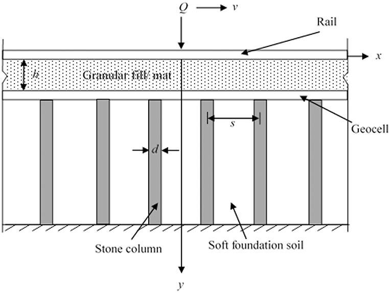
Figure 1. Longitudinal section of rail resting on geocell-stone column composite reinforced earth bed.
Analysis
The conceptual idealization of physical model (Figure 2) depicts the granular mat by a Pasternak shear layer (Selvadurai, 1979). The compressible nature of the fill/mat has been represented by stiffness k1. The poor soil and stone columns have been represented as Winkler springs of stiffnesses k2 = ks and k2 = kc, respectively. Viscous damping coefficients c1and c2 for upper and the lower soil layers, respectively, have also been considered in the analysis. An evenly distributed surcharge load γ1h over the full length of bottom beam has been accounted for, where h denotes the location of reinforcing beam with respect to top beam and γ1is the unit weight of the granular fill material. It is evident for track foundation system that when the load moves, rail tends to rise up at certain regions due to its inherent bending stiffness leading to its separation from the soil below. To include this effect appropriate contact conditions have been considered in the analysis.
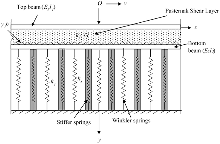
Figure 2. Idealized representation of the problem.
The governing differential equation of motion based on the idealized model for top and the bottom beam can be expressed as: -
Where, the deflections of top and the bottom beam have been denoted by y1 and y2, respectively, and deflection of ground surface by yg. g is the acceleration due to gravity and a contact function j(x, t) has been included in the equations to represent the tensionless behavior of the soil. Also, it should be noted that k2 = ks in soft soil region and k2 = kc within the stone column region.
The separation between top beam and the geocell-stone column composite foundation soil can be mathematically expressed as:
Solution of Developed Equations
In order to simplify the problem, a new variable ξ has been defined as ξ = x–vt, i.e., the distance from point of action of load in the quasi-stationary state. Equations (1) and (2) can now be modified as
and
The above equations can be rephrased by utilizing the dimensionless parameters mentioned below:
ξ*=; ; ; ; ; ; ; ; ; ; ; ; ; ; ; ; ; and , where L is half length of the beam. Thus, the generalized differential Equations (4) and (5) in non-dimensional form can be expressed as:
and
Equations (6) and (7) are discretised for an internal node, i using finite difference method and can be written as:
and
Where,
Mathematical expressions in Equation (3) can be modified as:
Boundary Conditions
Extent of the beams has been considered such that it behaves as an infinite beam (Selvadurai, 1979). Boundary conditions has been assumed according to Vlasov and Leontiev (1966) so as to obtain the solution of developed equation systems. The boundary conditions in non-dimensional form have been represented as:
For the top beam
For the bottom beam
Convergence Study and Input Parameter Details
Based on the mathematical model established above, a computer code has been developed. The entire extent of track-foundation system (−L ≤ x ≤ L) has been discretised by utilizing finite difference method. It has been found that there is negligible change (<1–2%) in the deflection profile when the number of nodes is increased from 5,001 to 8,001 nodes. Hence, the mesh with 5,001 nodes has been considered for the analysis. The tolerance factor has been specified to be 10−6 for the analysis based on convergence study.
The range of parameters have been assumed as per the Indian railway track conditions and the values considered have been given in Table 1. The magnitude of viscous damping (c1 and c2) has been calculated with the help of the following expressions:
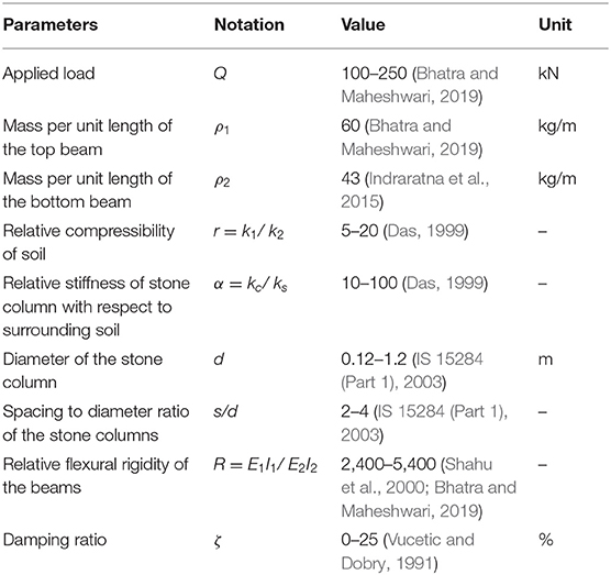
Table 1. Input parameters.
Results and Discussion
Validation
In the absence of experimental data in existing literature for validation purpose, the same has been done by comparing the results with those given by Hussein and Hunt (2006). The latter discussed and analyzed floating slab track model to determine the behavior of response and critical velocity of the system by utilizing Fourier transformation method. In the study, a plot of displacement of the rails vs. velocity of applied load was obtained for the following set of parameters: E1I1 = 10 × 106 N-m2, E2I2 = 1,430 × 106 N-m2, ρ1 = 100 kg/m, ρ2 = 3,500 kg/m, k1 = 40 × 106 N/m2, k2 = 50 × 106 N/m2, ζ1 = ζ2 = 5%, as considered by Hussein and Hunt (2006), to estimate critical velocity of the system. In order to verify proposed formulation, response obtained by current study for the similar conditions has been plotted and good agreement has been observed between the results as shown in Figure 3. Thus, verifying the adopted solution technique and methodology.
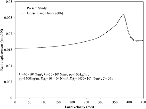
Figure 3. Validation.
When top beam is getting lifted from the ground surface due to tensionless nature of the foundation, the deflection in upward direction has been taken as negative deflection for presenting all the results.
Ground Improvement
The effect of inclusion of stone column on deflection profile of top beam for the parameters: Q = 175 kN, v = 36 m/s, k1 = 150 MN/m3, r = 10, E1I1 = 4,470 kN-m2, R = 3,000, G = 650 kN/m2, γ = 18 kN/m3, ρ1 = 60 kg/m, ρ2 = 43 kg/m, ζ = 10%, h = 0.15 m, α = 25, s/d = 2.5, and d/L = 0.004 has been shown in Figure 4. It has been observed that maximum non-dimensional deflection of top beam reduces by 58% indicating substantial improvement of the earth bed upon inclusion of stone columns. Furthermore, uplift of top beam has been observed to increase by 33% due to inclusion of stone columns.
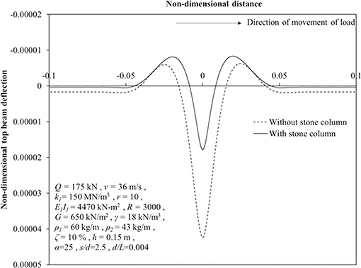
Figure 4. Deflection of top beam: the effect of stone column inclusion.
Influence of Tensionless Nature of Foundation
Figure 5 presents the comparison between normalized deflection profiles of top beam for tensionless foundation case with that for the perfect contact case (i.e., foundation reacts both in compression and tension). The value of parameters considered have been stated in the figure. It has been found that the maximum downward normalized deflection is mildly affected showing an increase from 1.72 × 10⁻⁵ to 1.79 × 10⁻⁵ i.e., only 4%, when the earth bed is considered to react only in compression. However, the maximum normalized upward deflection has been significantly affected due to tensionless behavior of foundation showing an increase from 3.6 × 10⁻⁷ to 8.3 × 10⁻⁶. It is evident that on considering tensionless behavior of the foundation bed, the maximum normalized upward deflection is immensely affected compared to the maximum normalized downward deflection. In view of this, tensionless behavior of soil should be considered while analyzing such systems.
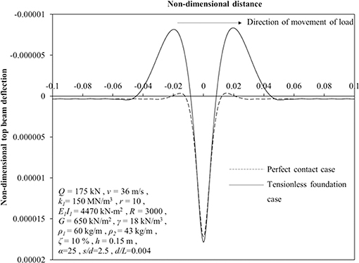
Figure 5. Deflection of top beam for perfect contact case and tensionless foundation case.
Parametric Study
Magnitude of Moving Load (Q)
Figures 6, 7 present the effect of magnitude of moving load on deflection and the bending moment profiles of top beam, respectively, for input parameters mentioned in the figures. It has been found that maximum downward as well as upward deflection reduces by 60 and 83%, respectively, when the magnitude of moving load is varied from 250 to 100 kN. Also, for the same variation, a reduction of 61 and 51% has been observed for maximum positive and negative bending moment in top beam.
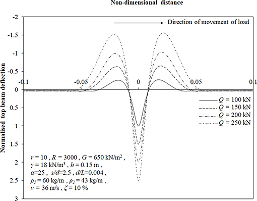
Figure 6. Deflection of top beam for various magnitudes of applied load.
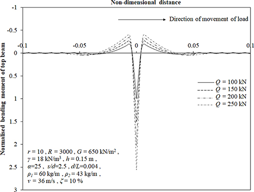
Figure 7. Bending moment profile of top beam for various magnitudes of applied load.
On further investigation with the same set of input values, it has been found that top beam begins to lift off the ground at a lower value of Q = 68 kN with the inclusion of stone columns. Without stone column, the onset of detachment has been observed at a higher value, Q = 124 kN which may be due to the reduced stiffness of the system which allowed more downward deflection of the top beam.
Relative Compressibility of Soil (r)
Figure 8 shows the result of variation in relative compressibility of soil on the deflection profile of the top beam. An increase of 48 and 12% in maximum downward and upward deflection of the top beam, respectively, has been found corresponding to an increase in ratio, r from 5 to 20. It can be concluded from these results that the downward deflection of top beam is more affected by the above variation compared to upward deflection which has further been discussed during the sensitivity analysis.
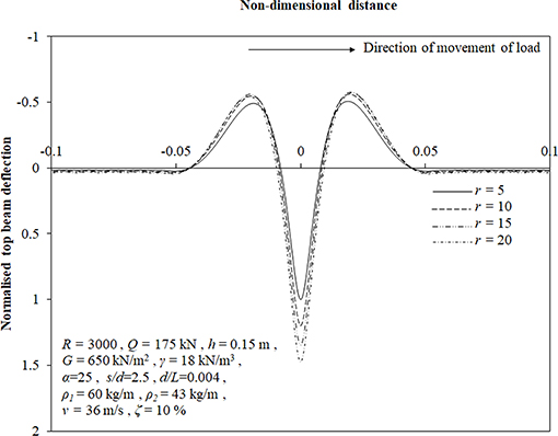
Figure 8. Deflection profile of top beam at different values of r.
Relative Stiffness of Stone Columns (α)
Deflection profile of the top beam for different values of α has been presented in Figure 9. On increasing α from 10 to 100, maximum downward deflection has been found to decrease by 25% whereas maximum upward deflection has been observed to increase by 22%. It has been observed that for higher increment of α i.e., from 50 to 100, the decrease in maximum downward deflection in only 4% as compared to 16% reduction when α is increased from 10 to 25. For the similar variation, increment of 2 and 14%, respectively, has been observed for maximum upward deflection. From these observations, it can be concluded that at a higher value of α, effect of its increment diminishes on the deflection.
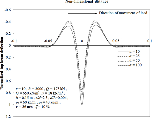
Figure 9. Deflection profile of top beam for various values of α.
Configuration of Stone Columns
The influence of variation in spacing at a specific diameter on deflection profile of the top beam has been presented in Figure 10A. On varying s/d ratio from 3.5 to 2, maximum downward and upward deflection has been found to decrease by 50 and 75%, respectively. This decrement in deflection for both the directions is justified as the number of stone columns increases on reducing s/d ratio.

Figure 10. (A) Deflection of top beam at different s/d values. (B) Deflection of top beam for various d/L values.
Figure 10B describes the effect of variation in diameter of stone columns on deflection profile of top beam for the set of input values stated in the figure. It has been found that maximum downward and upward deflection nominally decreases by 1.5 and 7%, respectively, when d/L ratio is increased from 0.0008 to 0.0016. However, on further increase in d/L ratio to 0.0048 and 0.008, the maximum deflection values increase by 58 and 80%, respectively. This may be due to the fact that now sufficient amount of soft soil material has been replaced by stiffer stone columns and in spite of reduction in number of stone columns, the deflections reduce upon increasing the diameter of stone columns.
Relative Flexural Rigidity of Beams (R)
Figure 11 shows the influence of relative flexural rigidity of beams on the deflection profile of top beam for considered set of input parameters. It has been found that maximum downward and upward deflection reduce by 28% and 66% on increasing ratio, R from 2,400 to 5,400. This reduction may be because higher values of R denotes lower flexibility of the top beam and consequently, the lower deflections.
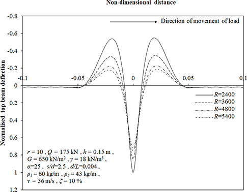
Figure 11. Deflection of top beam at different values of R.
Depth of Placement of Lower Beam (h)
Figure 12 presents the effect of location of bottom beam on the deflection profile of top beam. It has been observed that the variation in depth of bottom beam have substantial effect on upward deflection compared to the downward deflection which is negligibly affected. As the location of bottom beam has been varied from 0.05 to 0.45 m, maximum upward deflection of top beam has been found to reduce by 29%. It has also been observed that region of separation between top beam and the ground reduces on lowering the bottom beam till h = 0.57 m beyond which perfect contact is developed between them.
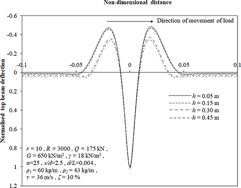
Figure 12. Deflection of top beam for different depths of placement of the bottom beam.
Velocity of Applied Load (v)
Figure 13 shows the influence of velocity of moving load on deflection profile of the top beam. The maximum downward deflection of the top beam has been observed to increase by only 3% due to variation in load velocity from 0 to 80 m/s. However, the maximum upward deflection increases by 7% when v is increased from 0 to 40 m/s and shoots up to 22% increment on increasing the load velocity to 80 m/s.
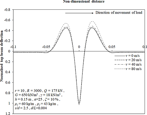
Figure 13. Deflection of top beam at different velocities of applied load.
Damping Ratio (ζ)
At lower velocity, it has been observed that bending of beams remain unaffected by variation in damping coefficients. At higher values of velocity (v = 85 km/h), on varying damping ratio from 0 to 25%, the maximum upward deflection has been found to increase by 8%. However, the maximum downward deflection of the top beam has still been observed to be unaffected by the variation. In view of nominal influence, this has not been depicted here.
Sensitivity Study
Figures 14A,B show the typical plot of sensitivity analysis for maximum downward and upward deflection of top beam, respectively, for the following input values: Q = 175 kN, v = 36 m/s, k1 = 150 MN/m3, r = 10, E1I1 = 4,470 kN-m2, R = 3,000, G = 650 kN/m2, γ = 18 kN/m3, ρ1 = 60 kg/m, ρ2 = 43 kg/m, ζ = 10%, h = 0.15 m, α = 25, s/d = 2.5 and d/L = 0.004. For the study, the maximum values of top beam deflection in both the directions for each ±20 and ±10% variations from the mean values have been obtained. These responses have been weighted with respect to maximum deflection in either direction for the mean value of respective parameters. It has been observed that the maximum upward deflection of top beam is substantially sensitive toward a greater number of parameters compared to its maximum downward deflection. However, the sensitivity of maximum downward deflection has been found to be more toward relative compressibility of the soil and relative stiffness of the stone column compared to its counterpart. Configuration of stone columns has been found to be one of the most influential parameter affecting the response of soil-foundation system.
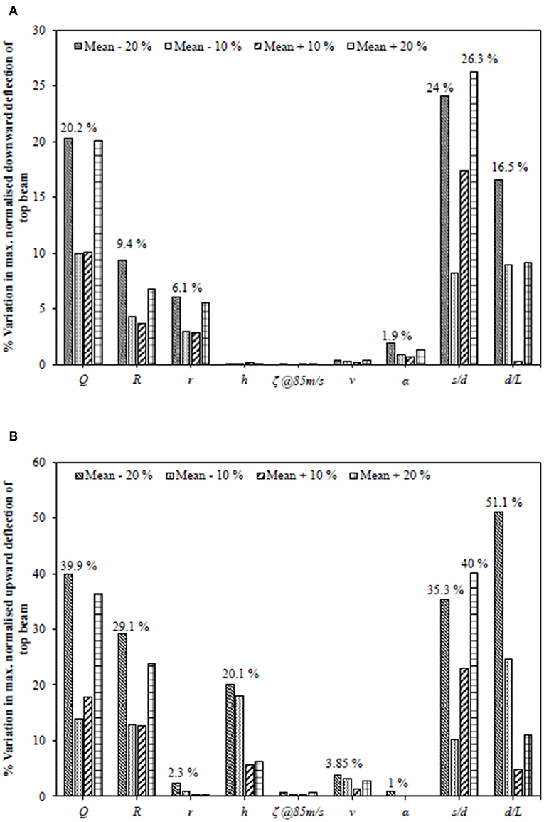
Figure 14. Sensitivity analysis: (A) downward deflection, (B) upward deflection of top beam.
Practical Relevance
A practitioner can consider the input values conforming to conditions on site and determine the deflection and bending moment values of the rails. Under the circumstances, where this deformation works out to be more than the allowable values as per required track performance (Beranek, 2000), the non-dimensional charts based on the parametric study can be used to consider befitting improvement characteristics like appropriate configurations of stone columns, depth of placement and rigidity of geocell layer, thickness of granular layer etc. so that the resulting response of rails are within the permissible limit.
In addition to this, the sensitiveness of the rail deflection toward variation in different parameters has been highlighted during the sensitivity analysis giving the idea of the impact of that particular parametric variation on the response of rail.
Conclusions
A study has been proposed in order to analyze the combined effect of stone column and geocell improved beds for rails lying over it exposed to moving point load. Tensionless behavior of earth beds has been modeled and included in the analysis. Based on results, the following conclusions can be deduced:
(i) Inclusion of stone columns resulted in 58% reduction in maximum downward deflection of top beam indicating significant improvement from settlement point of view.
(ii) Beginning of parting between top beam and the ground surface has been observed at a lower value of Q = 68 kN due to increased stiffness of the foundation on inclusion of stone columns.
(iii) A prominent increase of 48% in maximum downward deflection of top beam has been observed when relative compressibility of soil layers is increased from r = 5 to 20. The corresponding increment in maximum upward deflection has been found to be only 12%.
(iv) Significant reduction in maximum upward and downward deflection has been observed when s/d is varied from 3.5 to 2. For the case of variation in diameter of stone columns, these deflections are observed to initially reduce only to increase later when d/L is varied from 0.0008 to 0.008 based upon whether the phenomenon of replacement of soil by coarser material is dominant or reduction in number of stone columns.
(v) Maximum upward deflection of top beam has been observed to reduce by 66% on increasing relative flexural rigidity, R from 2,400 to 5,400.
(vi) For the top beam, the variation in location of the bottom beam from h = 0.05 to 0.45 m results in 29% reduction in the maximum upward deflection. Furthermore, the region of detachment between top beam and the ground has been found to reduce on increasing the depth of placement of the bottom beam till it develops perfect contact.
(vii) Maximum upward deflection of top beam has been found to rise up by 22% compared to 7% initial increment when the velocity is increased up to 80 m/s.
(viii) Sensitivity analysis conducted suggested that maximum upward deflection of top beam is exceptionally sensitive toward variation in most of the parameters compared to maximum downward deflection except for the case of relative compressibility of the soil and relative stiffness of the stone columns.
Data Availability Statement
All datasets generated for this study are included in the manuscript/supplementary files.
Author Contributions
PM formed the idea and algorithm of the work. SB developed computer program and implemented the algorithm and conducted detailed parametric study. All authors reviewed and accepted the final version.
Conflict of Interest
The authors declare that the research was conducted in the absence of any commercial or financial relationships that could be construed as a potential conflict of interest.
References
Arulrajah, A., Abdullah, A., Bo, M. W., and Bouazza, A. (2009). Ground improvement techniques for railway embankments. Proc. Inst. Civil Eng. Ground Improv. 162, 3–14. doi: 10.1680/grim.2009.162.1.3
Auersch, L. (2012). Dynamic behavior of slab tracks on homogeneous and layered soils and the reduction of ground vibration by floating slab tracks. J. Eng. Mech. 138, 923–933. doi: 10.1061/(ASCE)EM.1943-7889.0000407
Basu, D., and Rao, N. S. V. K. (2013). Analytical solutions for Euler – Bernoulli beam on visco-elastic foundation subjected to moving load. Int. J. Numerical Anal. Methods Geomech. 37, 945–960. doi: 10.1002/nag.1135
Beranek, D. A. (2000). Technical Instructions: Railroad Design and Rehabilitation. TI 850-02, AIR FORCE AFMAN 32-1125(I). Washington DC: Engineering and Construction Division, U.S. Army Corps of Engineers.
Bhatra, S., and Maheshwari, P. (2019). Double beam model for reinforced tensionless foundations under moving loads. KSCE J. Civil Eng. 23, 1600–1609. doi: 10.1007/s12205-019-1609-6
Chen, J. S., and Chen, Y. K. (2011). Steady state and stability of a beam on a damped tensionless foundation under a moving load. Int. J. Non Linear Mech. 46, 180–185. doi: 10.1016/j.ijnonlinmec.2010.08.007
Coşkun, I. (2000). Non-linear vibrations of a beam resting on a tensionless Winkler foundation. J. Sound Vib. 236, 401–411. doi: 10.1006/jsvi.2000.2982
Cui, X., Zhuang, Y., Hu, C., Liu, H., and Chiu, C. F. (2018). Improvement of soft foundations under a rapid transit tram rail system. Soil Mech. Found. Eng. 55, 181–189. doi: 10.1007/s11204-018-9523-3
Deng, H., Chen, K., Cheng, W., and Zhao, S. (2017). Vibration and buckling analysis of double-functionally graded Timoshenko beam system on Winkler-Pasternak elastic foundation. Composite Struct. 160, 152–168. doi: 10.1016/j.compstruct.2016.10.027
Duffy, D. G. (1990). The response of an infinite railroad track to a moving, vibrating mass. J. Appl. Mech. Div. ASME 57, 66–73. doi: 10.1115/1.2888325
Fryba, L. (1972). Vibration of Solids and Structures Under Moving Loads. London: Thomas Telford Ltd.
He, G., Li, X., and Lou, R. (2016). Nonlinear FEA of higer oder beam resting on tensionless foundation with friction. Geomechan. Eng. 11, 95–116. doi: 10.12989/gae.2016.11.1.095
Hussein, M. F. M., and Hunt, H. E. M. (2006). Modelling of floating-slab tracks with continuous slabs under oscillating moving loads. J. Sound Vibration 297, 37–54. doi: 10.1016/j.jsv.2006.03.026
Indraratna, B., Biabani, M. M., and Nimbalkar, S. (2015). Behavior of geocell-reinforced subballast subjected to cyclic loading in plane-strain condition. J. Geotech. Geoenv. Eng. 141, 04014081-1–16. doi: 10.1061/(ASCE)GT.1943-5606.0001199
IS 15284 (Part 1) (2003). Design and Construction for Ground Improvement – Guidelines. Part 1 Stone Columns. New Delhi: Bureau of Indian Standard.
Jaiswal, O. R., and Iyengar, R. N. (1997). Dynamic response of railway tracks to oscillatory moving masses. J. Eng. Mech. Div. ASCE 123, 753–757. doi: 10.1061/(ASCE)0733-9399(1997)123:7(753)
Kenney, J. T. Jr. (1954). Steady-state vibrations of beam on elastic foundation for moving load. J. Appl. Mech. Div. ASME 21, 359–364.
Kerr, A. D. (1974). The stress and stability analyses of railroad tracks. J. Appl. Mech. Div. ASME 41, 841–848. doi: 10.1115/1.3423470
Lin, L., and Adams, G. G. (1987). Beam on tensionless elastic foundation. J. Eng. Mech. ASCE 113, 542–553. doi: 10.1061/(ASCE)0733-9399(1987)113:4(542)
Maheshwari, P. (2014). Infinite beams on stone column reinforced tensionless earth beds under moving loads. Int. J. Geotech. Eng. 8, 21–25. doi: 10.1179/1938636213Z.00000000058
Maheshwari, P., Chandra, S., and Basudhar, P. K. (2004). Response of beams on a tensionless extensible geosynthetic-reinforced earth bed subjected to moving loads. Comput. Geotech. 31, 537–548. doi: 10.1016/j.compgeo.2004.07.005
Maheshwari, P., Chandra, S., and Basudhar, P. K. (2005). Steady state response of beams on a tensionless geosynthetic-reinforced granular fill-soft soil system subjected to moving loads. Soils Found. 45, 11–18. doi: 10.3208/sandf.45.5_11
Maheshwari, P., and Khatri, S. (2013). Response of infinite beams on geosynthetic-reinforced granular bed over soft soil with stone columns under moving loads. Int. J. Geomech. ASCE 13, 713–728. doi: 10.1061/(ASCE)GM.1943-5622.0000269
Maheshwari, P., and Viladkar, M. N. (2009). A mathematical model for beams on geosynthetic reinforced earth beds under strip loading. Appl. Math. Model. 33, 1803–1814. doi: 10.1016/j.apm.2008.03.009
Mallik, A. K., Chandra, S., and Singh, A. B. (2006). Steady-state response of an elastically supported infinite beam to a moving load. J. Sound Vib. 291, 1148–1169. doi: 10.1016/j.jsv.2005.07.031
Mohammadzadeh, S., Esmaeili, M., and Mehrali, M. (2014). Dynamic response of double beam rested on stochastic foundation under harmonic moving load. Int. J. Numerical Anal. Methods Geomech. 38, 572–592. doi: 10.1002/nag.2227
Rao, N. S. V. K. (1974). Onset of separation between a beam and tensionless foundation due to moving loads. J. Appl. Mech. Div. ASME 41, 303–305. doi: 10.1115/1.3423257
Raymond, G. P. (2002). Reinforced ballast behaviour subjected to repeated load. Geotextiles Geomembr. 20, 39–61. doi: 10.1016/S0266-1144(01)00024-3
Selvadurai, A. P. S. (1979). Elastic Analysis of Soil-Foundation Interaction. Amsterdam, Netherlands: Elsevier Scientific Publishing Company.
Shahu, J. T., Yudhbir, and Kameswara Rao, N. S. V. (2000). A rational method for design of railroad track foundation. Soils Found. 40. 1–10. doi: 10.3208/sandf.40.6_1
Torby, B. J. (1975). Deflection results from moving loads on a beam that rests upon an elastic foundation reacting in compression only. J. Appl. Mechanics. Div. ASME 42, 738–739. doi: 10.1115/1.3423677
Vlasov, V. Z., and Leontiev, U. N. (1966). Beams, Plates and Shells on Elastic Foundations, Israel Program for Scientific Translations. Jerusalem: Israel Program for Scientific Translations.
Vucetic, M., and Dobry, R. (1991). Effect of soil plasticity on cyclic response. J. Geotech. Eng. ASCE 117, 89–107. doi: 10.1061/(ASCE)0733-9410(1991)117:1(89)
Yuan, J., Zhu, Y., and Wu, M. (2009). Vibration characteristics and effectiveness of floating slab track system. J. Comput. 4, 1249–1254. doi: 10.4304/jcp.4.12.1249-1254
Zhang, L., Ou, Q., and Zhao, M. (2018). Double-beam model to analyze the performance of a pavement structure on geocell-reinforced embankment. J. Eng. Mech. 144, 06018002-1–7. doi: 10.1061/(ASCE)EM.1943-7889.0001453
Zhao, L. S., Zhou, W. H., Fatahi, B., Li, X., and Bin Yuen, K. V. (2016). A dual beam model for geosynthetic-reinforced granular fill on an elastic foundation. Appl. Math. Model. 40, 9254–9268. doi: 10.1016/j.apm.2016.06.003
Zhuang, Y., and Wang, K. (2017). Numerical simulation of high-speed railway foundation improved by PVD-DCM method and compared with field measurements. Eur. J. Env. Civil Eng. 21, 1363–1383. doi: 10.1080/19648189.2016.1170728
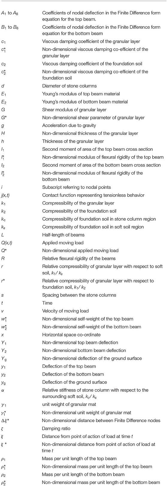
List of Notations
Keywords: rail tracks, tensionless foundation, moving load, geocell, stone columns
Citation: Bhatra S and Maheshwari P (2019) Modeling of Rail Tracks on Stone Column Reinforced Tensionless Foundations. Front. Built Environ. 5:122. doi: 10.3389/fbuil.2019.00122
Received: 25 July 2019; Accepted: 02 October 2019;
Published: 16 October 2019.
Edited by:
Castorina Silva Vieira, University of Porto, PortugalReviewed by:
Amarnath M. Hegde, Indian Institute of Technology Patna, IndiaSireesh Saride, Indian Institute of Technology Hyderabad, India
Copyright © 2019 Bhatra and Maheshwari. This is an open-access article distributed under the terms of the Creative Commons Attribution License (CC BY). The use, distribution or reproduction in other forums is permitted, provided the original author(s) and the copyright owner(s) are credited and that the original publication in this journal is cited, in accordance with accepted academic practice. No use, distribution or reproduction is permitted which does not comply with these terms.
*Correspondence: Priti Maheshwari, cHJpdGlfbWFoZXNoMjAwMUB5YWhvby5jb20=