 Matteo Bruggi
- Department of Civil and Environmental Engineering, Politecnico di Milano, Milan, Italy
The conceptual design of grid systems in tall buildings is addressed by combining optimization and multiscale analysis of lattice structures. Macroscopic properties of lattices with given cross-section are available in the literature for different cell topologies. A multi-material optimization problem is formulated to find the distribution of a prescribed discrete set of candidate cross-sections and shapes such that the structural weight of the grid is minimized under constraints on the lateral displacements of the building. Preliminary numerical simulations are shown, addressing the design of tall buildings that employ diagrids and hexagrids.
1. Introduction
Diagrids and hexagrids are special tubular structures that adopt inclined members instead of conventional vertical columns to carry both vertical and lateral loads (see e.g., Mele et al., 2014; Montuori et al., 2015). It is well-known that perimeter grids are an efficient solution to cope with horizontal forces in high-rise buildings. Among the other advantages, a perimeter resisting system maximizes lever arms to face overturning moments due to lateral loads. By using inclined members instead of frame rectangular grids, weight is reduced and undesired shear lag effects can be mitigated (see e.g., Shi and Zhang, 2019). Indeed, several iconic tall buildings have been built over the last decades exploiting these concepts, thus combining structural functionality and aesthetics.
Diagrids employ diagonally intersecting members that give rise to triangular shapes. A stiffness-based method for the preliminary design of diagrids was formulated in Moon et al. (2007). Investigations on the optimal layout of the members of a diagrid can be found e.g., in Moon (2010), Montuori et al. (2014), and Angelucci and Mollaioli (2017).
Hexagrids draw inspiration from honeycombs, in which hexagonal cells make the resisting structure. Mechanical properties of hexagrids and diagrids are extensively investigated and critically compared in Montuori et al. (2015), addressing several geometric layouts. A homogenization-based procedure is formulated that is able to perform the multiscale analysis of high-rise buildings adopting a cantilever beam model. An equivalent material is derived whose elastic and shear moduli depend not only on the geometrical properties of the grid, but also on the cross-section and the material properties of its members. This approach is especially conceived for regular patterns, in which the representative volume element is detected as the smallest basic cell that can tessellate the whole grid. Upon introduction of suitable correction factors, the same approach can be extended to irregular patterns, see in particular the Voronoi grids investigated in Angelucci and Mollaioli (2018) and Mele et al. (2019). This method provides the designer with a sound and effective tool to cope both with conventional and innovative structural skins for tall buildings.
Design strategies for diagrids and Voronoi-like tall buildings that are based on size optimization can be found e.g., in Angelucci and Mollaioli (2017, 2018) and Tomei et al. (2018). Advances in optimization of high-rise building structures are reviewed in Aldwaik and Adeli (2016). Among the others, reference is made to the work in Lagaros (2014), which addresses large-scale optimization problems for real-world structures using metaheuristic approaches and parallel computing, and to Mavrokapnidis et al. (2019), performing the environmental assessment of cost optimized structural systems in tall buildings. Within the framework of methods for discrete variable structural optimization (see e.g., Arora, 2002), reference is made in particular to Van Mellaert et al. (2018), implementing a mixed-integer linear programming approach that handles binary variables to choose the member profiles from a catalog. This method has the peculiar feature of being globally convergent (see also Van Mellaert et al., 2016).
Among the methods used for the conceptual design of tall buildings, topology optimization (Bendsøe and Kikuchi, 1988) is a powerful tool to sketch lightweight and stiff systems to resist lateral forces. A distribution of a limited amount of material is sought that minimizes a prescribed objective function, such as the strain energy stored in the body, given a set of constraints, such as the available amount of material. Optimal layouts made of void and solid material can be found by adopting the conventional Solid Isotropic Material with Penalization (SIMP) (Bendsøe and Sigmund, 2004) to interpolate the elastic properties with respect to the minimization unknown, i.e., the point-wise material density. Alternatively, the optimization can be performed by gradually removing inefficient materials from a continuum design domain (see Liang et al., 2000). The achieved results can be also seen as optimal load paths (see e.g., Bruggi, 2016).
Among the topology optimization approaches for high-rise buildings, reference is made in particular to Stromberg et al. (2011), introducing pattern gradation for the design of bracing structures, and Beghini et al. (2015), combining continuum and discrete elements to design lateral force resisting systems not only for stiffness but also for global stability (see also Stromberg et al., 2012). Reference is also made to the application of a three-dimensional implementation of the so-called ground structure approach in Zegard and Paulino (2015) to sketch optimal perimeter grids.
Within the above framework, this contribution addresses the conceptual design of grid systems in tall buildings by combining topology optimization and multiscale analysis of cellular solids (see e.g., Gibson and Ashby, 1988). Instead of adopting a multiscale cantilever beam model, a three-dimensional box-shaped structure is used as the design domain for the generation of optimal grid systems whose panels can be seen as lattice structures. Among the others, the work in Vigliotti and Pasini (2012) provides analytical expressions for the macroscopic constitutive tensors that describe the elastic behavior of triangular and hexagonal lattices with prescribed reference dimension, cross-section, and material. Following Gibiansky and Sigmund (2000) and Stegmann and Lund (2005), a multi-material topology optimization problem is formulated to distribute a discrete set of lattices using continuous variables. Each phase corresponds to a candidate lattice with prescribed features in terms of geometrical properties and features of the constituent elements (see also Alzahrani et al., 2015; Han and Lu, 2018). The distribution of cross-sections and shapes that minimizes the weight of the structural grid is sought under constraints on the lateral displacements of the building. Patches are used to enforce that the same lattice is employed at a certain height or within a minimum contiguous area. This also reduces the number of optimization parameters involved in the optimization. Preliminary numerical results are presented to assess the method and investigate features of the achieved optimal solutions.
The algorithm presented in this work should be intended as a conceptual design tool to allow the designer investigate and optimize alternative grids, using the same finite element model. Two peculiar features can be pointed out, referring to the analysis approach and the to the optimization method. While most of the existing approaches of multi-scale analysis of tall buildings employ homogenization to derive the macroscopic elastic modula for a cantilever beam model, see in particular Montuori et al. (2014), the macroscopic in-plane elastic constants are used in this contribution to address a shell model of the box-shaped grid. Hence, instead of using size or parametric optimization for truss/beam models, see in particular Zegard and Paulino (2015) and Tomei et al. (2018), or SIMP-based topology optimization, see in particular Stromberg et al. (2011), a multi-material topology optimization approach is conceived to handle the distribution of a discrete set of lattices throughout the shell model.
The paper is organized as follows. Section 2 provides details on the macroscopic modeling of the structural grids and presents the multiscale optimization approach. Section 3 reports results of the numerical simulations performed on three-dimensional shell and beam models, addressing tall buildings with square and hexagonal plan. Section 4 formulates comments on the achieved results and draws conclusions.
2. Materials and Methods
2.1. Macro-Scale Elastic Properties of Diagrids and Hexagrids as Lattice Structures
The work in Vigliotti and Pasini (2012) presents a multiscale procedure for the linear analysis of components made of two-dimensional lattices. The method can be applied to pin-jointed and rigid-jointed lattices with arbitrary cell topology. Two levels are defined: the micro-scale one, referring to the trusses/beams, and the macro-scale one, i.e., that of the component. The macro-scale properties of the equivalent lattice material are determined by writing the micro-scale deformation work as a function of the macro-scale strain field. Assuming plane stress, the cartesian components of the macro-scale stress tensor σij are re-gathered in the array σ = [σ11 σ22 σ12]T and, analogously, ε = [ε11 ε22 ε12]T for the components of the macro-scale strain tensor εij. Hence, σ = Cε. Two types of lattices are addressed in this contribution, as shown in Figure 1. Both the herein considered triangular and honeycomb lattices have a six-fold rotational symmetry, so that isotropic constitutive relations are found by means of the multiscale procedure.
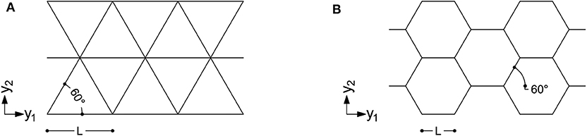
Figure 1. Two lattices used in structural grids: (A) an isotropic triangular lattice of a diagrid; (B) an isotropic hexagonal lattice of a hexagrid (B) (drawn in the micro-scale reference system).
Denoting by A and I the area and the moment of inertia of the cross-section, respectively, L the reference length of the geometry and E the elastic modulus of the material, the stiffness matrix of an isotropic diagrid-like lattice of the type in Figure 1A can be written at the macro-scale as:
According to the above equation, the bending contribution to the strain energy is always negligible with respect to the stretching one. Indeed, diagrids are stretching-dominated structures.
The macro-scale stiffness matrix of an isotropic hexagrid-like lattice of the type in Figure 1B can be written as:
see also Gonella and Ruzzene (2008). According to the above equation, the bending contribution to the strain energy is always significant, except for hydrostatic stresses when it is null. Indeed, hexagrids are bending-dominated structures (see e.g., Ashby, 2006).
The lattices in Figure 1 are well-suited for structural grids. The contribution in Montuori et al. (2015) concludes that an angle of 60° for the diagonal members can be considered as the best compromise of structural needs, such as stiffness and weight, and architectural ones, such as visual density, both for diagrids and hexagrids. However, the procedure introduced in Vigliotti and Pasini (2012) is general and can be used to derive constitutive matrices of other anisotropic lattices that can be similarly handled within the formulation presented in the following.
Alternative approaches can be implemented to recover the elastic properties of the lattices at the macro-scale. Among the others, reference is made to Kumar and McDowell (2004). In this work, displacements and rotations of a lattice unit cell were expressed as second order Taylor expansions about the cell centroid, with the aim of equating the deformation energy of the discrete lattice to that of a micropolar continuum. This enriched kinematics is conceived to cope with macroscopic specimens whose dimensions are not far from those of the microstructure. It is finally remarked that the optimization procedure proposed in the sequel may be straightforwardly adapted to deal with a micropolar material model (see e.g., Bruggi and Taliercio, 2012).
2.2. Optimization With a Discrete Set of Cross-Sections
Diagrids and hexagrids with given reference length L are assumed to be made of elements whose cross-section should be selected within a prescribed set, meaning that the available area A and moment of inertia I have discrete values. Hence, the relevant lattice materials should be described referring to a discrete set of macroscopic stiffness matrices. A multi-material methodology is adopted to handle this problem within the context of topology optimization by distribution of isotropic material. A continuous interpolation of the macroscopic stiffness matrix is adopted following an original extension of the SIMP that was proposed in Gibiansky and Sigmund (2000) and reviewed in Stegmann and Lund (2005) to handle m phases of material along with a void one. It reads:
where C is the stiffness matrix of the resulting material, 0 < ρ0 ≤ 1 is a continuous minimization variable that controls the distribution of material and void, whereas 0 ≤ ρi ≤ 1 with i = 1, …, m govern the stiffness contributions of the material phases, being Ci the constitutive matrix of the i-th material phase.
In the herein considered problem, there is no void phase. Indeed, it is assumed that the whole building envelope is endowed with a structural grid having varying cross-section and shape. A basic lattice that adopts the smallest among the candidate cross-sections provides a minimum stiffness all over the design domain. The goal of the optimization is distributing local increments of the macroscopic stiffness matrix in order to meet some design requirements. This can be performed re-writing Equation (3) as:
The above equation handles m+1 cross-sections, i.e., the basic one along with m bigger cross-sections. The continuous variables 0 ≤ ρi ≤ 1 with i = 1, …, m are minimization unknowns that govern the lattice stiffness: C0 is the macroscopic stiffness matrix of the basic cross-section (the weakest among the available ones), whereas Ci refers to the i-th cross-section other than the basic one. The parameter p is a penalization power assumed equal to 3.
Having the aim of using few different sections in the grid, the assumption m = 3 will be used to perform numerical simulations. Writing out the expression in Equation (4) to handle four cross-sections one has:
An interpolation of the type in Equation (5) is very efficient in pushing the weights of the stiffness increments, i.e., the optimal values of the continuous variables ρi, toward the bounds 0 and 1. This performs the aimed distribution of the prescribed set of candidate cross-sections. Table 1 reports triplets of ρi that recover the macroscopic stiffness matrix of four candidate lattices through Equation (5).
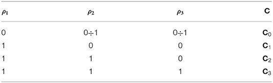
Table 1. Macroscopic stiffness matrix retrieved by Equation (5) depending on the values of ρi.
As reported in Stegmann and Lund (2005), the original interpolation of Equation (3) can get stuck in local optima, especially depending on the number of material phases to be distributed along with void. Different starting points can be adopted to investigate optimality of the results achieved using Equation (5). In the case of several candidate cross-sections, the interpolation originally introduced in Stegmann and Lund (2005) to cope with the discrete material optimization of multi-layered composite structures can be alternatively implemented to address this issue. Reference is also made to Wang and Wang (2004) and Sanders et al. (2018) for detailed discussions on the problem of structural shape and topology optimization in a multi-material domain.
2.3. Minimum Weight Design of Structural Grids Under Displacement Constraints
The preliminary design of grid systems can be formulated as a displacement-constrained minimum weight problem. A finite element discretization of the building envelope is operated, adopting a patch-wise approximation of the unknown fields ρi. A patch is a set of elements that share the same cross-section (see Stegmann and Lund, 2005). In the j-th of the n patches, m minimization unknowns are defined: xp, i for i = 1, …, m are the discrete counterparts of ρi in Equation (5). In the e-th of the nel elements in the mesh, the element-wise values xe, i descend from those of xp, i in the relevant patch.
Accordingly, the problem can be stated as:
In the above statement, the objective function is the weight of the grid system, which is computed through the sum of the element-wise contributions We. For the e-th element, this is evaluated assuming the interpolation in Equation (4) with p = 1. Indeed, p = 3 is conventionally used for stiffness interpolation to penalize intermediate densities, whereas a penalization p > 1 for the approximation of We is expected to be detrimental in a minimum weight formulation. Considering a problem with four candidate cross-sections, the weight of the bars that fall within the e-th finite element reads:
where We, 0 refers to the cross-section of the basic lattice (the lighter one), whereas the terms We, i−We, 0 define the weight increments due to each one of the remaining m candidate sections. Regardless of the values of the minimization unknowns, the coefficients within square brackets in Equation (7) add up to unity. The combined adoption of the interpolations in Equations (5) and (7) is especially conceived to achieve 0-1 solutions, see results in section 3.
Equations (6a) and (6c) prescribe the discrete equilibrium of the structure under horizontal actions that act along two orthogonal axes of the plan of the building, z1 and z2 respectively. The global stiffness matrix is computed assembling the element-wise contribution Ke that account for the in-plane stiffness given by Equation (4) and, particularly, Equation (5). The load vectors F1 and F2 allow computing the nodal displacements vectors U1 and U2, referring to actions along z1 and z2, respectively. The scalar quantities u1 and u2 stand for the average values of the horizontal displacements computed at the top of the building for the relevant load case. Equations (6d) and (6e) enforce a prescribed limit ulim to the above quantities, which is assumed as 1/500 of the height of the building Hz3.
It must be remarked that the proposed framework is intended as a conceptual design tool to investigate and optimize alternative grids, at a preliminary level, using the same discretization. Indeed, the adopted multi-scale analysis avoids implementing a different beam model for each solution to explore. The proposed formulation is based on a stiffness design criterion, which is implemented under the assumption of linear elastic behavior of the material and small strain theory. However, it could be straightforwardly endowed with constraints enforcing maximum stresses and minimum critical loads to control strength and buckling failure, respectively. The work in Vigliotti and Pasini (2012) provides analytical expressions not only for the macroscopic in-plane stiffness of the lattices, but also for the internal forces as a function of the components of the macro-strain field. This could be used to enforce stress constraints and local buckling constraints on each member of the grid, whereas an eigenvalue-based approach could be implemented to control global buckling (see e.g., Bendsøe and Sigmund, 2004).
2.4. Numerical Implementation
A nested design and analysis approach is used, adopting four-node flat shell finite elements to model the macroscopic properties of the structural grids. The implemented finite element is obtained by combining the in-plane stretching behavior of a plane stress element with the bending behavior of a thin plate element. As already mentioned, the in-plane stiffness comes from the element-wise application of the interpolation introduced in sections 2.1 and 2.2, whereas a negligible out-of-plane stiffness is prescribed to all the elements. In the numerical simulations presented in the following, the plane stress element implements the isotropic material laws in Equations (1) and (2) along with unitary thickness (1mm); the plate element uses the same material properties, but the thickness is fictitiously assumed equal to 10−4mm.
The problem in Equation (6) is attacked via sequential convex programming, adopting the Method of Moving Asymptotes (MMA) (Svanberg, 1987) as minimizer. MMA was originally conceived to attack structural optimization problems and is well-suited to handle multi-constrained problems, see also the application in Bruggi (2020). The computation of the sensitivity of the constraints with respect to the minimization unknowns is required at each iteration. The adjoint method is adopted in this regard (see e.g., Bendsøe and Sigmund, 2004). The average horizontal displacement at the top of the building uk can be written as:
with k = 1, 2. In the above equation, Lk is a vector made of zeros except for the entries referring to the top horizontal displacements in the zk-axis. In these entries, it takes the value 1/N, with N number of points belonging to the top floor. The scalar quantity uk does not change if one adds at the right hand side of Equation (7) a zero function that involves the discrete equilibrium in Equation (6b) or Equation (6c) for k = 1 and k = 2 respectively, i.e.,:
where λk is any arbitrary but fixed vector. After rearrangement of terms, the derivative of uk with respect to the l-th set of element-wise unknowns may be computed as:
where λk satisfies the adjoint equation:
The sensitivity of Ke with respect to the l-th set of element-wise unknowns is computed by derivation of Equation (4), where C0 and Ci are fixed matrices accounting for the prescribed candidate lattices. This sensitivity is null, if e ≠ l.
The derivative of uk with respect to the h-th set of patch-wise unknowns may be computed by adding up the relevant derivatives of the elements in the patch.
At each iteration of the minimization procedure four linear systems are solved to evaluate constraints and their sensitivities via finite element (FE) analysis, i.e., Equations (6b), (6c), and (10) for k = 1, 2.
Figure 2 gives a flowchart of the implemented algorithm.
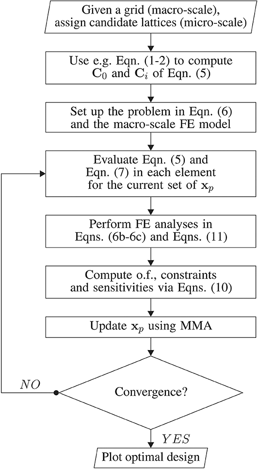
Figure 2. Flowchart of the proposed tool.
3. Results
Structural grids for tall buildings having a square or a hexagonal base are investigated by means of the proposed approach. At first, the multiscale analysis described in section 2.1 is assessed by comparing the achieved results with those found adopting a conventional three-dimensional beam-based analysis. Then, a preliminary optimization is performed addressing different patches. The weight of the analyzed/optimized structural grids are reported in Table 2.
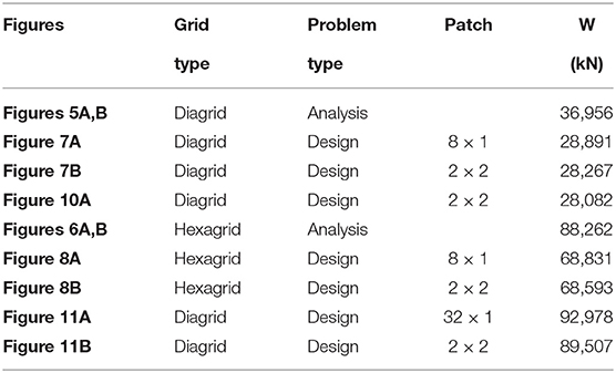
Table 2. Tonnage of the analyzed/optimized structural grids.
Hexagrids take full advantage of rigid diaphragms (RDs) to reduce their (bending-dominated) deformability, whereas (stretching-dominated) diagrids are less affected by such a stiffening. In the numerical simulations that follow, the nodes at the same height are enforced to be part of a rigid diaphragm, if not differently specified (see section 3.1). Constraints equations are used in the analysis to prescribe that the in-plane motion of all the points on a floor diaphragm is that of a rigid body. The nodes of a panel that lie on a RD preserve their mutual distance in the horizontal direction, thus affecting the relevant component of the strain in the plane of the panel and, consequently, the overall flexural stiffness of the grid. The arising stiffening effect is analogous to the confinement provided by the steel lamina on the rubber layers in a laminated elastomeric bearing, see in particular Montuori et al. (2015) and Mele et al. (2019).
As a simplification, it is assumed that all the horizontal forces acting upon the building (such as wind actions) are carried by the structural grid in the envelope, whereas no vertical force is considered, if not differently specified (see section 3.3). Indeed, the adopted displacement-constrained problem addresses horizontal compliance and disregards the vertical one. Rigid-jointed grids are considered throughout the section.
Diagrids and hexagrids investigated in the numerical simulations are handled through the regular discretization shown in Figure 3: continuous lines stand for bars in the grid; dash lines stand for shell finite elements; dash-dot lines stand for a typical patch of 2 × 2 finite elements that share the same cross-section and shape. For each one of the finite elements, the ratio of the vertical size to the horizontal one reads .
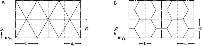
Figure 3. Layout of the (A) diagrids and (B) hexagrids investigated in the numerical simulations: continuous lines stand for bars in the grid; dash lines stand for elements; dash-dot lines stand for a typical patch of 2 × 2 elements sharing the same cross-section.
It must be remarked that no match is required, in principle, between the geometry of the finite element discretization (at the macro-scale) and the geometry of the lattices (at the micro-scale) (see Vigliotti and Pasini, 2012). Any variation in the orientation of the members at the micro-scale can be straightforwardly dealt with at the macro-scale by means of an anisotropic constitutive law. Patches can be used to control mesh dependence of the optimal layouts when refined discretizations are implemented. The adoption of a structured mesh of the type in Figure 3 allows simplifying the construction of the relevant beam models, as used in the following for comparisons.
3.1. Multiscale Analysis vs. Beam-Based Analysis of a Tall Building
A high-rise building having square plan with dimension Bz1 = Bz2 = 48m and height Hz3 = 207.85m is considered (see Figure 4A). A uniform distribution of the horizontal load is assumed along the height of the building with intensity pz1 = pz2 = 96kN/m, being z1 and z2 the baricentrical axes of the building plan. Each of the two loads is applied along the four corners of the building, being equally divided among them.
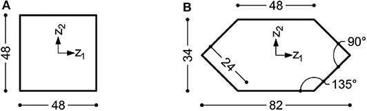
Figure 4. Dimensions (in m) of the floors of two tall buildings: (A) a square plan building and (B) a hexagonal plan building (drawn in the macro-scale reference system).
The multiscale approach described in section 2.1 is applied to the analysis of the building, assuming different structural grids with constant cross-section along the height. The computed displacements are compared with those found through conventional three-dimensional beam models that use the geometry and the cross-section of the relevant grid. The analyses address the grids represented in Figure 3: (a) a diagrid having reference length L = 8m, made of tubes with circular hollow cross-section, diameter ϕ = 558mm and thickness th = 16mm, slenderness (tonnage 36956kN); (b) a hexagrid having reference length L = 4m, made of tubes with square hollow cross-section, side l = 650mm and thickness th = 40mm, slenderness (tonnage 88262kN). The elastic modulus of steel is 210GPa in all the simulations considered in the following.
Multiscale simulations are performed using the same regular finite element mesh with d1 = 6m and d2 = 6.93m. The vertical size of the finite element d2 = 6.93m is twice the story height. There are 8 × 30 finite elements in each panel of the three-dimensional grid. Beam-based simulations are performed accounting for the effective geometry of the grids, implementing two different finite element models. Comparisons are performed either neglecting the contribution of the floors or assuming rigid diaphragms (RDs). Due to the symmetry of the problem, the same average displacement is found at the top both for the horizontal actions acting along z1 and z2. As already mentioned, no optimization is considered in this section. However, the adopted lattices have been selected such that, in case of RDs, the top displacements of the grid are feasible with respect to the considered constraints on the lateral stiffness of the building. These layouts may be regarded as reference solutions to be improved by means of Equation (6), as addressed in the following section.
Values of uk are reported in Table 3 for each one of the considered finite element simulations, along with the number of elements and nodes of the finite element models. The uk values achieved through a multiscale analysis of the diagrid are almost the same as those computed by beam-based models, regardless of the assumption on RDs. Conversely, in the case of the hexagrid, uk values computed via the multiscale analysis are affected by a larger error, especially when rigid diaphragms are considered. This is in agreement with the original validation reported in Vigliotti and Pasini (2012) when dealing with plane stress problems. The multiscale analysis exhibited extreme accuracy in the evaluation of the displacement field for stretching-dominated lattices, whereas bending-dominated ones were found to be affected by an error of some percentage points or less, depending on the reference dimension L. The accuracy of the results delivered by a multiscale analysis increases if the size of the unit cell decreases with respect to the size of the component. Hence, ratios and should be carefully considered when accurate results are needed, especially when dealing with the multiscale analysis of hexagrids. Also, the enforcement of RDs could be effectively performed through a modification of the macroscopic properties of the lattice structure that accounts for this constraint at the micro-scale level, see in particular Montuori et al. (2015).
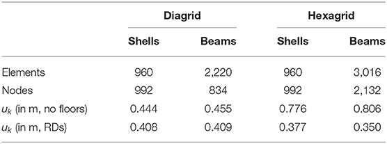
Table 3. Multiscale analysis vs. beam-based analysis of a tall building with square plan employing a diagrid/hexagrid with constant cross-section.
Deformed shapes (with magnification factor 100) are reported in Figures 5, 6, for the diagrid and the hexagrid, respectively. A very good agreement of the multiscale solutions is found with respect to the reference beam-based results. As expected, the stiffening effect due to the rigid diaphragms is mild in case of the diagrid, whereas it is noticeable for the hexagrid. RDs allow for a reduction of approximately 10 and 50% in the former and latter case, respectively. Looking at the whole hexagrid system as a cantilever beam, both the beam-based model and the multiscale analysis predict a bending-dominated deformed shape. A transition to a shear dominated one can be observed upon introduction of RDs, especially in the middle and upper part of the building.
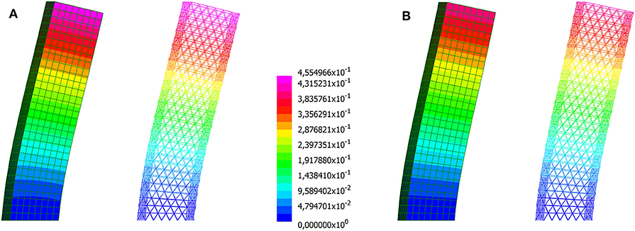
Figure 5. Building with square plan employing a diagrid with constant cross-section. Magnified deformed shapes computed through the multiscale approach and a beam model: (A) neglecting the contribution of the floors; (B) assuming rigid diaphragms (displacements in m).
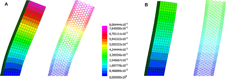
Figure 6. Building with square plan employing a hexagrid with constant cross-section. Magnified deformed shapes computed through the multiscale approach and a beam model: (A) neglecting the contribution of the floors; (B) assuming rigid diaphragms (displacements in m).
3.2. Macroscopic Optimization of Grids for a Tall Building With Square Plan
The proposed approach of optimal design by distribution of lattice structures is applied to the tall building analyzed in the previous section, making the assumption of rigid diaphragms. A diagrid and a hexagrid are considered, prescribing four candidate cross-sections that share the same external dimensions. This preserves the visual density of the grid and is expected to simplify the handling of structural joints.
The considered diagrid system has reference length L = 8m and is made of tubes having circular hollow cross-sections with diameter ϕ = 558mm, the same used in the simulations presented in the previous section. The four thickness candidates read th = 8, 10, 16, 25mm. Two different patches are considered in the optimization, i.e., 8 × 1 elements or 2 × 2 elements. The former calls for a uniform distribution of lattice structures over the height in each panel, whereas the latter leaves more freedom enforcing a minimum contiguous area for each cross-section. The formulation in Equation (6) is effective in achieving pure 0–1 values for the four sets of variables that govern the interpolation in Equation (5). Optimal distributions of discrete thicknesses are found at convergence. The achieved solutions are represented in Figures 7A,B, that report maps of the thicknesses within the design domain, i.e., the structural grid. Both constraints are active at convergence, meaning that top displacements uk at convergence are equal to the enforced limit 1/500Hz3 = 0.416m. The patch 8 × 1 finds a height-dependent distribution of optimal thicknesses that is the same in the four sides of the envelope. The upper half of the building is made of the basic lattice (th = 8mm), whereas increasingly thicker cross-sections are distributed toward its base. This solution saves a remarkable amount of material (more than 20%) with respect to the constant thickness design with th = 16mm used in section 3.1. The layout found by means of the 2 × 2 patch is a few hundreds kN lighter than the previous optimal solution. Again, a symmetric solution arises as expected. Thicker cross-sections are used at the corners, especially next to the base where the highest values of strain energy are expected to be stored. Indeed, it may be shown that a displacement-constrained minimum weight problem is fully equivalent to a weight-constrained minimization of the strain energy (see e.g., Bendsøe and Sigmund, 2004).
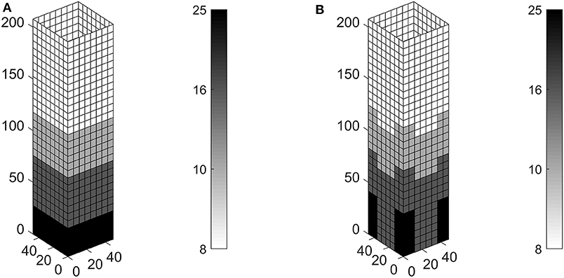
Figure 7. Optimal thickness (mm) in the diagrid of a tall building with square plan, using four circular hollow cross-sections with ϕ = 558mm: (A) patch with 8 × 1 elements, W = 28, 891kN; (B) patch with 2 × 2 elements, W = 28, 267kN.
A similar investigation is performed on the building addressing a hexagrid system. It has reference length L = 4m and is made of tubes having square hollow cross-section with side l = 650mm, i.e., the same used in the simulations presented in the previous section. The four thickness candidates read th = 20, 32, 40, 50mm. Again, for the two different patches considered in the optimization, i.e., 8 × 1 elements and 2 × 2 elements, both displacement constraints are active at convergence. The achieved results are shown in Figures 8A,B, respectively. The patch 8 × 1 finds a height-dependent distribution of optimal thicknesses adopting the basic lattice (th = 20mm) in the upper half of the building, whereas increasingly thicker cross-sections are distributed toward its base. This optimal design saves more than 20% with respect to the tonnage of the hexagrid with uniform thickness th = 40mm that was analyzed in section 3.1. Again, the design found by means of a patch 2 × 2 is a few hundreds kN lighter than the solution achieved for the patch 8 × 1. The layout of the optimal reinforcement is different with respect to that presented in Figure 7B. The thickest cross-section is used at the corners of the grid in the vicinity of the base of the building, whereas the same thickness is provided both at the corners and within the bulk elsewhere. This provides additional stiffness not only to bending actions but also to shear ones, see comments on the deformed shapes of Figures 5, 6 in the previous section.
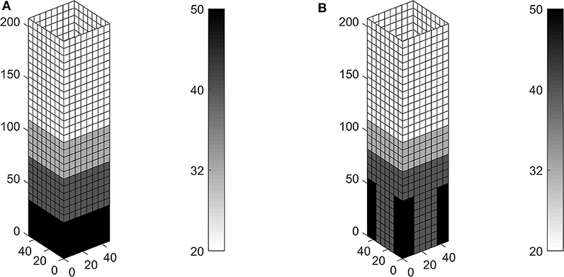
Figure 8. Optimal thickness (mm) in the hexagrid of a tall building with square plan, using four square hollow cross-sections with l = 650mm: (A) patch with 8 × 1 elements, W = 68, 831kN; (B) patch with 2 × 2 elements, W = 68, 593kN.
The achieved results have been checked using different starting guesses. Figure 9 reports history plots of the objective function for the optimal distributions of lattices discussed above when starting from xp, i = 1 for i = 1, …, m in each patch. Simulations adopting the 8 × 1 patch call for 4·120 unknowns, whereas those based on the 2 × 2 patch involve 4·240 variables. The stopping criterion is such that the maximum variation of the unknowns between two subsequent iterations should not exceed 10−3. In all the considered cases, less than 25 iterations are needed to achieve convergence smoothly. As detailed in section 2.4, four FE analyses are needed in each iteration, two for the evaluation of the displacement constraints in Equations (6–6) and two for the evaluation of the adjoint problems in Equation (10) to perform sensitivity analysis.
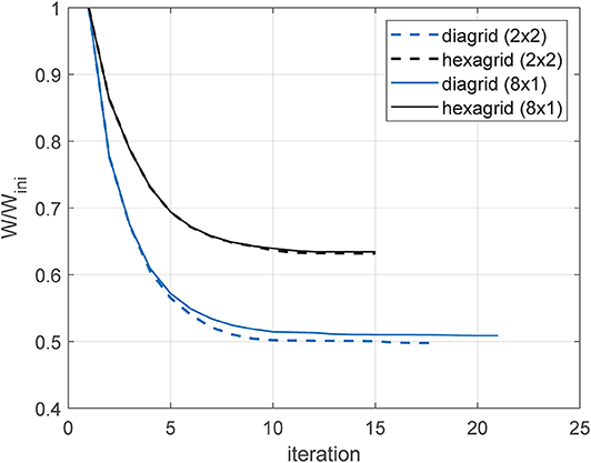
Figure 9. History of the objective function for the optimal distributions of cross-sections shown in Figures 7, 8.
More than four cross-sections could be considered in the implemented numerical tool. From an optimization point of view, the adoption of a larger set of candidates is expected to provide some gain in terms of total weight. However, this depends on the selected set of cross-sections and the adopted patches. Referring on the computational cost, any additional lattice that is considered in the optimization involves a new vector of minimization unknowns, whereas the number of FE analyses per iteration remains the same, as well as the size of the linear system of the equilibrium equations. It must be remarked that standard applications of topology optimization handled via MMA involve tens or hundreds of thousands of unknowns (see Bendsøe and Sigmund, 2004). Due to the non-convexity of SIMP-based topology optimization problems, converge to a global optimum can not be guaranteed. As detailed in section 2.2, modifications in the interpolation of Equation (4) could be conveniently embedded and tested in Equation (6), with the aim of selecting the most effective approximation for the considered multi-material problem depending on m. This point is currently under investigation.
The proposed approach of optimal design can be also used to distribute different layouts within the same structural grid. Two diagrids with reference length L = 16m and L = 8m are considered, defining four candidate equivalent stiffness matrices. The diagrid with reference length L = 16m is made of tubes having circular hollow cross-sections with diameter ϕ = 558mm and thickness th = 12.5mm or th = 16mm, labeled diagrid type A and B, respectively; the diagrid with reference length L = 8m consists of tubes with the same cross-section type and equal external diameter but thickness th = 16mm or th = 20mm, called type C and D, respectively. The optimal distribution of lattice structures is sketched in Figure 10, along with the (magnified) deformed shapes computed through the multiscale and a beam model. The displacements computed at the top of the grids are in good agreement: u1 = u2 = 0.416m for the shell model vs. u1 = u2 = 0.421mm for the beam model. The achieved solution is the lightest among those shown in this section.
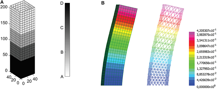
Figure 10. A diagrid with varying cross-sections and varying reference dimensions for a tall building with square plan: (A) optimal solution, W = 28, 082kN; (B) magnified deformed shapes computed through the multiscale approach and a beam model (displacements in m).
3.3. Macroscopic Optimization of the Grid for a Tall Building With Hexagonal Plan
A high-rise building having hexagonal plan with dimension Bz1 = 82m and Bz2 = 34m and height Hz3 = 207.85m is considered (see Figure 4B). The geometry of the plan is loosely based on that of the iconic Pirelli Tower in Milan (see e.g., Ziegler, 2009). A uniform distribution of the horizontal load is considered along the height of the building with intensity pz1 = 68kN/m and pz2 = 140kN/m, being z1 and z2 the baricentrical axes of the building plan. Rigid diaphragms are assumed in the simulations. Horizontal loads are applied as point forces acting in the centroid of each diaphragm.
The proposed approach of optimization by distribution of lattice structures is used to address the design of a diagrid by means of two patches: a 32 × 1 patch, collecting all the elements at the same height and a patch made of 2 × 2 elements enforcing a minimum contiguous area for each cross-section. In both cases the diagrid system has reference length L = 8m and is made of tubes having circular hollow cross-section with diameter ϕ = 762mm. The four thickness candidates read th = 10, 25, 35, 55mm.
The optimal solutions are presented in Figure 11. Only one constraint is active at convergence, that is the one enforcing un upper bound for the displacement along the z2 axis, as expected. Lighter cross-sections are used for increasing height when using the 32 × 1 patch. The patch made of 2 × 2 elements allows saving an additional 4% with respect to the tonnage of the previous solution. The thicker cross-section is used only at the base of the long panels, whereas intermediate thicknesses are extensively used in the lower and middle regions of the short ones. Looking at the whole diagrid system as a cantilever beam, the horizontal forces applied along the z2 axis are responsible for bending and shear actions that should be mainly handled by the long and the short panels, respectively.

Figure 11. Optimal thickness (mm) in the diagrid of a tall building with hexagonal plan, using four circular hollow cross-sections with ϕ = 762mm: (A) patch with 32 × 1 elements, W = 92, 978kN; (B) patch with 2 × 2 elements, W = 89, 507kN.
To validate the latter layout, a beam model is built adopting the optimal distribution of cross-sections that is represented in Figure 11B. The (magnified) deformed shapes computed through the multiscale approach and the beam model are shown in Figures 12A,B for pz1 and pz2, respectively. Notwithstanding the irregular shape of the plan of the building and the stiffness that varies all over the grid, the displacements computed at the top of the tower are almost equal: u1 = 0.059m and u2 = 0.416m for the shell model, whereas u1 = 0.058m and u2 = 0.416m for the beam model.
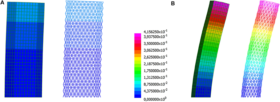
Figure 12. Building with hexagonal plan employing a diagrid with varying cross-sections: magnified deformed shapes computed through the multiscale approach and a beam model for (A) pz1 and (B) pz2 (displacements in m).
A further investigation is performed for the case with patches made of 2 × 2 elements, including vertical forces. A uniformly distributed load pz3 = −100kN/m is applied along the top edge of every shell, i.e., along the perimeter of the building each m in height. Four load cases are considered: vertical forces are coupled with the effect of lateral forces, i.e., ±pz1 and ±pz2. Hence, two additional constraints are considered in the optimization problems with respect to Equations (6d) and (6e) to control the absolute value of the lateral deflections at the top of the building. The same result as in Figure 11B is found. Indeed, no variation in the lateral deflections is expected when adding a centered axial force in the cantilever-like building. According to the beam model, the maximum axial force in compression is 26426kN when both pz2 and pz3 loads are considered, whereas 11394kN when pz2 acts alone. Both values are far below the Euler's critical load of the lattice element at the base of the building, where these forces arise.
4. Discussion
A numerical method has been presented to cope with the conceptual design of structural grids in tall buildings, specially concerning diagrids and hexagrids. Such kind of regular grids can be seen as lattice structures, i.e., tessellations of the skin of the building made through triangular and hexagonal shapes. Analytical expressions for the components of their in-plane macroscopic constitutive matrix are available in the literature depending on the reference dimension, the adopted cross-section and the constituent material. Elastic constants found through the multiscale approach for pin-jointed and rigid-jointed lattices introduced by Vigliotti and Pasini (2012) have been implemented and investigated in this study addressing isotropic lattices. Any homogenization approach resulting in a isotropic or anisotropic constitutive law for a Cauchy material can be alternatively adopted to derive effective properties of the lattice structures.
A multi-material topology optimization problem has been formulated to distribute a discrete set of lattices using a set of continuous variables. Each candidate lattice has prescribed geometrical properties and features of the constituent elements, and is fully characterized by its effective constitutive matrix. The design domain is a three-dimensional box-shaped structure, i.e., the skin of the building, which is discretized using two-dimensional elements. Patches of elements are used to enforce that the same lattice is distributed at a certain height of the building or within regions having minimum contiguous area. The objective function is the weight of the structural grid, whereas constraints are enforced on the lateral displacements of the building.
Numerical simulations have been performed in section 3.1 to assess the accuracy of the implemented multiscale analysis when considering three-dimensional assemblages of diagrid and hexagrid panels with constant cross-section. The deformed shapes computed by means of the shell model match quite well those retrieved by three-dimensional beam models, independently on the type of the grid or whether rigid diaphragms are adopted. Referring to the top displacements, high accuracy is found in the case of stretching-dominated patterns (diagrids), whereas results for bending-dominated ones (hexagrids) are more affected by the size of the microstructure with respect to the panels. For the considered numerical simulations, the error is less than 3% in the former case, whereas it ranges between 4 and 8% in the latter. This follows from the original validation of the multiscale method for two-dimensional media.
Preliminary applications of the proposed optimization approach have been performed for tall buildings with regular (square) or irregular (hexagonal) shape of the plan. The implemented algorithm succeeds in finding layouts with varying cross-section and/or varying geometry that save weight with respect to reference solutions using a single feature all over the grid. Smooth convergence to 0–1 values is reported for the whole set of variables that control the distribution of multiple lattices (see section 3.2). Optimal height-dependent layouts are found for the building with square plan that save more than 20% in weight with respect to reference solutions employing uniform diagrids or hexagrids. The efficiency of height-dependent optimal layouts can be further improved adopting smaller patches. This specially applies to the case of irregular shape of the plan of the building (see section 3.3), in which an additional 4% saving is shown with respect to the height-dependent solution. Two of the achieved optimal distributions of lattice shapes and cross-sections have been implemented in three-dimensional beam models, recovering the same degree of accuracy that was found for grid structures with constant features.
A limited number of variables is handled by the proposed multiscale approach to perform the analysis and the optimization tasks, see Table 3. Several configurations of geometrical patterns and cross-sections can be investigated by means of a single finite element model. This allows for an efficient exploration of different optimal solutions, as needed when addressing the conceptual design of a structural grid. Accurate optimization tasks can be subsequently operated in view of the detailed design stage using e.g., size optimization.
The proposed approach can be generalized for several other objectives and constraints, including inter-story drift, eigenfrequencies, critical loads, and strength of the elements. Indeed, the implemented multiscale analysis allows evaluating forces in the elements of the lattice by post-processing the macroscopic strain field, whereas the adopted approach of mathematical programming is well-suited to handle multi-constrained optimization. The implemented displacement-constrained formulation may be straightforwardly extended to handle uncertainties in the load amplitude, see in particular Balogh et al. (2018).
Data Availability Statement
All datasets generated for this study are included in the article.
Author Contributions
MB conceived, designed, and performed this study.
Conflict of Interest
The author declares that the research was conducted in the absence of any commercial or financial relationships that could be construed as a potential conflict of interest.
Acknowledgments
MB gratefully acknowledges Professor Krister Svanberg, KTH Royal Institute of Technology Stockholm, for providing the MMA code.
References
Aldwaik, M., and Adeli, H. (2016). Advances in optimization of highrise building structures. Struct. Multidisc. Optim. 50, 899–919. doi: 10.1007/s00158-014-1148-1
Alzahrani, M., Choi, S., and Rosen, D. W. (2015). Design of truss-like cellular structures using relative density mapping method. Mater. Des. 85, 349–360. doi: 10.1016/j.matdes.2015.06.180
Angelucci, G., and Mollaioli, F. (2017). Diagrid structural systems for tall buildings: changing pattern configuration through topological assessments. Struct. Design Tall Spec. Build. 26:e1396. doi: 10.1002/tal.1396
Angelucci, G., and Mollaioli, F. (2018). Voronoi-like grid systems for tall buildings. Front. Built Environ. 4:78. doi: 10.3389/fbuil.2018.00078
Arora, J. S. (2002). Methods for discrete variable structural optimization. Recent Adv. Opt. Struct. Des. 1–40. doi: 10.1061/40492(2000)23
Ashby, M. F. (2006). The properties of foams and lattices. Philos. Trans. R. Soc. A 364, 15–30. doi: 10.1098/rsta.2005.1678
Balogh, B., Bruggi, M., and Lógó, J. (2018). Optimal design accounting for uncertainty in loading amplitudes: a numerical investigation. Mech. Based Des. Struct. Mach. 46, 552–566. doi: 10.1080/15397734.2017.1362987
Beghini, L. L., Beghini, A., Baker, W. F., and Paulino, G. H. (2015). Integrated discrete/continuum topology optimization framework for stiffness or global stability of high-rise buildings. J. Struct. Eng. 141. doi: 10.1061/(ASCE)ST.1943-541X.0001164
Bendsøe, M. P., and Kikuchi, N. (1988). Generating optimal topologies in structural design using a homogenization method. Comput. Methods Appl. Mech. Eng. 71, 197–224. doi: 10.1016/0045-7825(88)90086-2
Bendsœ, M. P., and Sigmund, O. (2004). Topology Optimization. Theory, Methods and Applications. Berlin; Heidelberg: Springer-Verlag.
Bruggi, M. (2016). A numerical method to generate optimal load paths in plain and reinforced concrete structures. Comput. Struct. 170, 26–36. doi: 10.1016/j.compstruc.2016.03.012
Bruggi, M. (2020). A constrained force density method for the funicular analysis and design of arches, domes and vaults. Int. J. Solids Struct. 193–194, 251–269. doi: 10.1016/j.ijsolstr.2020.02.030
Bruggi, M., and Taliercio, A. (2012). Maximization of the fundamental eigenfrequency of micropolar solids through topology optimization. Struct. Multidisc. Optim. 46, 549–560. doi: 10.1007/s00158-012-0779-3
Gibiansky, L. V., and Sigmund, O. (2000). Multiphase composites with extremal bulk modulus. J. Mech. Phys. Solids 48, 461–498. doi: 10.1016/S0022-5096(99)00043-5
Gibson, L., and Ashby, M. (1988). Cellular Solids: Structure and Properties. Cambridge: Cambridge University Press.
Gonella, S., and Ruzzene, M. (2008). Homogenization and equivalent in-plane properties of two-dimensional periodic lattices. Int. J. Solids Struct. 45, 2897–2915. doi: 10.1016/j.ijsolstr.2008.01.002
Han, Y., and Lu, W. F. (2018). A novel design method for nonuniform lattice structures based on topology optimization. J. Mech. Des. Trans. ASME 140. doi: 10.1115/1.4040546
Kumar, R., and McDowell, D. (2004). Generalized continuum modeling of 2-d periodic cellular solids. Int. J. Solids Struct. 41, 7399–7422. doi: 10.1016/j.ijsolstr.2004.06.038
Lagaros, N. D. (2014). A general purpose real-world structural design optimization computing platform. Struct. Multidisc. Optim. 49, 1047–1066. doi: 10.1007/s00158-013-1027-1
Liang, Q. Q., Xie, Y. M., and Steven, G. P. (2000). Optimal topology design of bracing systems for multistory steel frames. J. Struct. Eng. N. Y. 126, 823–829. doi: 10.1061/(ASCE)0733-9445(2000)126:7(823)
Mavrokapnidis, D., Mitropoulou, C. C., and Lagaros, N. D. (2019). Environmental assessment of cost optimized structural systems in tall buildings. J. Build. Eng. 24:100730. doi: 10.1016/j.jobe.2019.100730
Mele, E., Fraldi, M., Montuori, G. M., Perrella, G., and Della Vista, V. (2019). Hexagrid-voronoi transition in structural patterns for tall buildings. Frattura Integr. Strutt. 13, 186–208. doi: 10.3221/IGF-ESIS.47.15
Mele, E., Toreno, M., Brandonisio, G., and De Luca, A. (2014). Diagrid structures for tall buildings: case studies and design considerations. Struct. Des. Tall Spec. Build. 23, 124–145. doi: 10.1002/tal.1029
Montuori, G. M., Fadda, M., Perrella, G., and Mele, E. (2015). Hexagrid - hexagonal tube structures for tall buildings: patterns, modeling, and design. Struct. Des. Tall Spec. Build. 24, 912–940. doi: 10.1002/tal.1218
Montuori, G. M., Mele, E., Brandonisio, G., and De Luca, A. (2014). Geometrical patterns for diagrid buildings: exploring alternative design strategies from the structural point of view. Eng. Struct. 71, 112–127. doi: 10.1016/j.engstruct.2014.04.017
Moon, K., Connor, J. J., and Fernandez, J. E. (2007). Diagrid structural systems for tall buildings: Characteristics and methodology for preliminary design. Struct. Des. Tall Spec. Build. 16, 205–230. doi: 10.1002/tal.311
Moon, K. S. (2010). Stiffness-based design methodology for steel braced tube structures: a sustainable approach. Eng. Struct. 32, 3163–3170. doi: 10.1016/j.engstruct.2010.06.004
Sanders, E. D., Aguiló, M. A., and Paulino, G. H. (2018). Multi-material continuum topology optimization with arbitrary volume and mass constraints. Comput. Methods Appl. Mech. Eng. 340, 798–823. doi: 10.1016/j.cma.2018.01.032
Shi, Q., and Zhang, F. (2019). Simplified calculation of shear lag effect for high-rise diagrid tube structures. J. Build. Eng. 22, 486–495. doi: 10.1016/j.jobe.2019.01.009
Stegmann, J., and Lund, E. (2005). Discrete material optimization of general composite shell structures. Int. J. Numer. Methods Eng. 62, 2009–2027. doi: 10.1002/nme.1259
Stromberg, L. L., Beghini, A., Baker, W. F., and Paulino, G. H. (2011). Application of layout and topology optimization using pattern gradation for the conceptual design of buildings. Struct. Multidisc. Optim. 43, 165–180. doi: 10.1007/s00158-010-0563-1
Stromberg, L. L., Beghini, A., Baker, W. F., and Paulino, G. H. (2012). Topology optimization for braced frames: combining continuum and beam/column elements. Eng. Struct. 37, 106–124. doi: 10.1016/j.engstruct.2011.12.034
Svanberg, K. (1987). The method of moving asymptotes-a new method for structural optimization. Int. J. Numer. Methods Eng. 24, 359–373. doi: 10.1002/nme.1620240207
Tomei, V., Imbimbo, M., and Mele, E. (2018). Optimization of structural patterns for tall buildings: the case of diagrid. Eng. Struct. 171, 280–297. doi: 10.1016/j.engstruct.2018.05.043
Van Mellaert, R., Lombaert, G., and Schevenels, M. (2016). Global size optimization of statically determinate trusses considering displacement, member, and joint constraints. J. Struct. Eng. 142. doi: 10.1061/(ASCE)ST.1943-541X.0001377
Van Mellaert, R., Mela, K., Tiainen, T., Heinisuo, M., Lombaert, G., and Schevenels, M. (2018). Mixed-integer linear programming approach for global discrete sizing optimization of frame structures. Struct. Multidisc. Optim. 57, 579–593. doi: 10.1007/s00158-017-1770-9
Vigliotti, A., and Pasini, D. (2012). Linear multiscale analysis and finite element validation of stretching and bending dominated lattice materials. Mech. Mater. 46, 57–68. doi: 10.1016/j.mechmat.2011.11.009
Wang, M. Y., and Wang, X. (2004). "color" level sets: a multi-phase method for structural topology optimization with multiple materials. Comput. Methods Appl. Mech. Eng. 193, 469–496. doi: 10.1016/j.cma.2003.10.008
Zegard, T., and Paulino, G. H. (2015). Grand3-ground structure based topology optimization for arbitrary 3D domains using matlab. Struct. Multidisc. Optim. 52, 1161–1184. doi: 10.1007/s00158-015-1284-2
Keywords: diagrids, hexagrids, high-rise buildings, structural optimization, discrete material optimization, multiscale analysis, lattice structures
Citation: Bruggi M (2020) Conceptual Design of Diagrids and Hexagrids by Distribution of Lattice Structures. Front. Built Environ. 6:80. doi: 10.3389/fbuil.2020.00080
Received: 30 October 2019; Accepted: 05 May 2020;
Published: 02 June 2020.
Edited by:
Mattias Schevenels, KU Leuven, BelgiumReviewed by:
Antonio Formisano, University of Naples Federico II, ItalyElena Mele, University of Naples Federico II, Italy
Copyright © 2020 Bruggi. This is an open-access article distributed under the terms of the Creative Commons Attribution License (CC BY). The use, distribution or reproduction in other forums is permitted, provided the original author(s) and the copyright owner(s) are credited and that the original publication in this journal is cited, in accordance with accepted academic practice. No use, distribution or reproduction is permitted which does not comply with these terms.
*Correspondence: Matteo Bruggi, bWF0dGVvLmJydWdnaUBwb2xpbWkuaXQ=