 Simon Steffen
 Stefanie Weidner
 Lucio Blandini
- Institute for Lightweight Structures and Conceptual Design (ILEK), University of Stuttgart, Stuttgart, Germany
Due to the already high and still increasing resource consumption of the building industry, the imminent scarcity of certain building materials and the occurring climate change, new resource- and emission-efficient building technologies need to be developed. This need for new technologies is further amplified by the continuing growth of the human population. One possible solution proposed by researchers at the University of Stuttgart, and which is currently further examined in the context of the Collaborative Research Centre (SFB) 1244 Adaptive Skins and Structures for the Built Environment of Tomorrow is that of adaptivity. The integration of sensors, actuators, and a control unit enables structures to react specifically to external loads, when needed (e.g., in the case of high but rare loads). For example, adaptivity in load-bearing structures allows for a reduction of deflections or a homogenization of stresses. This in its turn allows for ultra-lightweight structures with significantly reduced material consumption and emissions. To reach ultra-lightweight structures, i.e., adaptive load-bearing structures, two key questions need to be answered. First, the question of optimal actuator placement and, second, which type of typology (truss, frame, etc.) is most effective. One approach for finding the optimal configuration is that of the so-called influence matrices. Influence matrices, as introduced in this paper, are a type of sensitivity matrix, which describe how and to which extend various properties of a given load-bearing structure can be influenced by different types of actuation principles. The method of influence matrices is exemplified by a series of studies on different configurations of a truss structure.
Introduction
The cement industry alone causes 5.4% (United Nations Environment Programme, 2019; Kelleter et al., 2020) of the global emissions of greenhouse gases and up to 10% of the total anthropogenic CO2 emissions (Scrivener et al., 2018). Overall, the building industry accounts for 35% of all global CO2 emissions, thus being a significant contributor to the ongoing climate change. Furthermore, 35% of the global energy consumption can be attributed to the built environment and 50% of the global resource consumption (UNEP, 2011; Sobek, 2016), leading to an ongoing depletion of vital resources, like sand (Peduzzi, 2014). The global growth of population and the increasing wealth in several parts of the world further intensify this effect (UN, 2019). Therefore, new building technologies and solutions are needed, which allow for a substantial reduction in emissions and resource consumption. Adaptive load-bearing structures, meaning structures with integrated active elements, i.e., sensors and actuators, have been put forward as a promising approach. The integration of such active elements allows an adaptive structure to monitor its stress state and to react accordingly. In case of rarely occurring, high external loads, the structure may induce forces counteracting those from the external load, respectively change its stiffness distribution to homogenize stresses and strains (Sobek and Teuffel, 2001; Senatore et al., 2018a), induce counter deformations (Sobek et al., 2002; Senatore et al., 2018b; Kelleter et al., 2020), or generate shape changes to establish a more efficient load transfer (Neuhaeuser et al., 2013; Reksowardojo et al., 2019), thus increasing structural performance. Due to this increase in performance, the passive elements of the adaptive structure can be dimensioned for lower, more frequently occurring loads, which reduces the structures' resource consumption and embodied energy while using comparatively little operational energy (Senatore et al., 2018c; Schlegl et al., 2019). While there are early examples of supporting structures with integrated active components (e.g., Domke, 1992), most studies concentrate on the possibilities of active control of the dynamic properties of a given structure (Soong and Manolis, 1987; Reinhorn et al., 1992; Holnicki-Szulc et al., 1998; Issa et al., 2010). The manipulation of quasi-static deflections and internal forces with the declared goal of a resource- and emission-efficient design as formulated in Sobek et al. (2006) and Sobek (2016) is still relatively new. This approach separates adaptive systems into three different states: first, the passive state, in which the structure acts as a conventional system under external load; second, the active state, in which the structure is subjected to actuation; and third, the adaptive state, the superposition of passive and active states. The adaptive state is the desired state of an adaptive system, which has to be established through actuation (active state) from a given passive state. Achieving load-bearing structures with an optimal resource and emission efficiency requires precise knowledge about the optimal amount and position of actuators for a given structure. Teuffel (2004) offers a first approach for truss structures, the load path management, which is built upon in Senatore et al. (2019) to optimize the structure in regards to overall energy consumption using the integrated force method (Patnaik, 1973), resulting in a new integral formulation to optimize adaptive structure in regards to overall energy consumption. Reksowardojo et al. (2020) presents a method for stress homogenization through large shape changes, i.e., geometric non-linearity, for trusses. In Wagner et al. (2018) and Böhm et al. (2019), Gramian-based approaches are described, which select actuated elements with the help of a greedy algorithm. Underlying the above mentioned methods are matrices, which contain information on how a given structure can be influenced by the actuation of each individual structural element. These sensitivity matrices, or influence matrices—analogous to the theory of influence lines—are used to determine the optimal actuator placement. In this paper, the reverse approach is tested. Investigating how variations of a load-bearing structure affect the contents of influence matrices generates answers for the overarching question: which topologies (respectively typologies) of truss and beam structures are most efficient for adaptive structures?
In Derivation, a general form of influence matrices is derived, which is further specified in Influence Matrices of Axial Forces, for the two actuation types presented in Derivation. In Example, different configurations of the same basic truss structure are analyzed using the beforehand derived influence matrices, highlighting how individual changes to a structural system correlate with its adaptability. The results are summarized and discussed in Result Discussion and Generalization. Large Scale Prototype High Rise provides a concise description of an experimental high-rise building, which will be used for further experimental validation of the actuation concepts and the findings of this paper. A conclusion and outlook are given in Conclusion.
Influence Matrices
Actuation Types
In this paper, two different types of linear actuation are considered (Figure 1)—serial actuation (a) and parallel actuation (b). In the case of serial actuation, an actuator is integrated into the load path of the structure, whereas parallel actuation adds an actuator parallel to an existing passive element (Weidner et al., 2018). The actuator force resulting from actuator extension is defined as positive and the actuator force from retraction as negative.
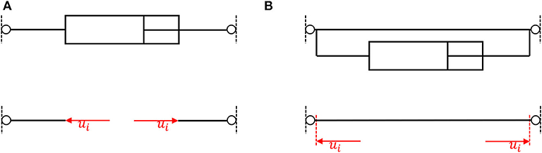
Figure 1. (A) Serial actuation and (B) parallel actuation and their respective free-body diagrams.
Derivation
For a given adaptive load-bearing structure, with n degrees of freedom and m actuators, the linear system of equations for static equilibrium can be written as
where K ∈ ℝnxn is the stiffness matrix, q ∈ ℝn is the vector of deformation, and f ∈ ℝn is the force vector—separated into external forces fext and actuation forces fact. As influence matrices investigate how a given structure reacts to actuation, the external forces fext can be set to zero. The vector of actuation forces fact is calculated from an input matrix B ∈ ℝnxm, which maps the actuator forces u ∈ ℝm of the individual actuator elements onto the respective global degrees of freedom as nodal forces
Each column vector bi ∈ ℝn
thus describes the orientation and the connectivity of each respective actuator element. Any output y ∈ ℝp of interest can be calculated from the vector of deformations q using
where C ∈ ℝpxn is an output matrix that has to be computed according to the desired output y. In case of serial actuation, a second output matrix, the feedthrough matrix D ∈ ℝpxm, may be required, which takes the actuation forces u into account:
Integrating Equations (1) and (2) into Equation (5) and setting fext to zero yields
To compute the influence of the actuation, each structural element is successively actuated by a unit load (number of actuators m = number of elements), expanding the load vector u into a matrix:
with I being the identity matrix in ℝmxm and ui therefore denoting the actuation of the ith element. Substituting the above into Equation (6) provides the equation, with which influence matrices E ∈ ℝpxm are calculated:
Influence matrices can also be used to calculate the required actuation forces u for any desired (adaptive) state yadaptive from a given passive state ypassiv (cf. Sobek et al., 2006) using
and solving for u
with (·)+ denoting the Moore–Penrose Pseudoinverse (Penrose, 1955).
Influence Matrices of Axial Forces
The influence matrix of axial forces due to parallel linear actuation EN, p,
describes how the axial forces of a given load-bearing structure can be manipulated by parallel linear actuation of each individual element. The output matrix CN ∈ ℝmxm therefore needs to calculate the axial forces from the resulting vector of deformation q and can be computed as
where Kelem ∈ ℝmxm is a diagonal matrix, containing the axial stiffness of each element of the load-bearing structure. Accordingly, the influence matrix of axial forces due to serial linear actuation EN, s computes the equivalent for serial linear actuation:
In this case, the additional feedthrough matrix DN ∈ ℝmxm is needed, subtracting the unit load of actuation once from the axial forces in the actuator element, as the axial load of a serial actuator is equivalent to the already applied force couple of nodal loads (cf. Figure 1).
Thus, the entry eN, ij of the ith row and jth column of the influence matrix of axial forces EN depicts the axial force in element i due to actuation of the element j. For truss structures the influence matrix of axial forces due to serial linear actuation EN, s is equivalent to the negative inverse of the redundancy matrix R ∈ ℝmxm described in Ströbel (1996) and Wagner et al. (2018).
Further types of influence matrices can be derived from Equation (8), e.g., an influence matrix of deformations, or one of bending moments. Similarly, other actuation types can be examined if their actuation principle can be formulated according to Equation (2).
Example
To showcase the method of influence matrices, different variations of the modular truss structure displayed in Figure 2 have been investigated. Each module was 1 m wide and high. The structural members were initially assigned an E modulus of 100 MPa and a quadratic cross-section of 0.01 m2 (cf. Table 1). The structures were modeled in ANSYS Mechanical APDL 17.2, using link180 and beam188 elements. The computation and analyses of influence matrices were done with MATLAB R2018a.
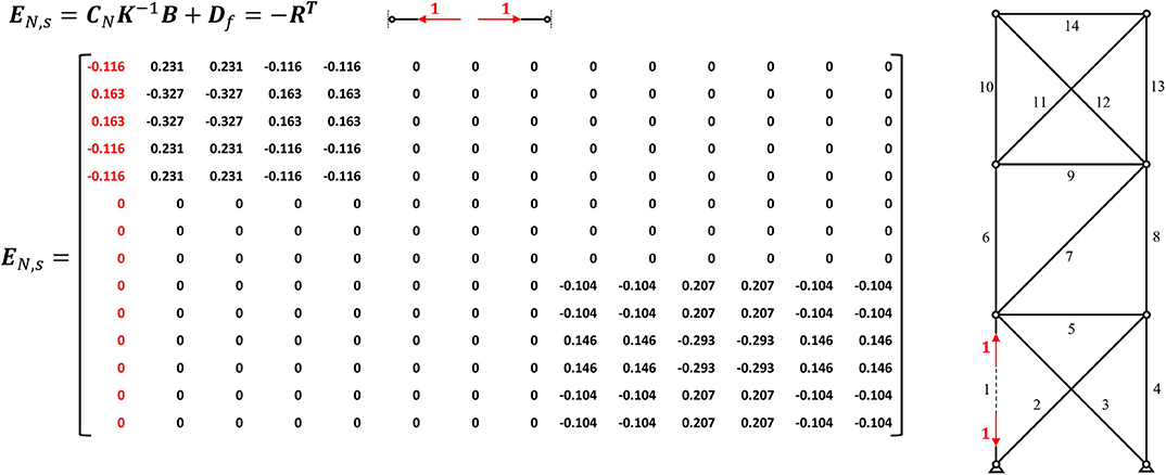
Figure 2. Influence matrix of axial forces due to serial linear actuation EN, s of an exemplary truss.
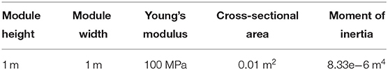
Table 1. Overview of the initially chosen structural properties of the example structure.
Statically Determinate Substructure
The resulting influence matrix of axial forces due to serial linear actuation EN, s is depicted in Figure 2. The matrix can be divided into three sections: the left section E1−5, which corresponds to the lowest module, a middle matrix E6−8 containing only zeros, equating to elements 6–8, and the right part E9−14, which matches the top module. It can further be observed that the ranks of the left (E1−5) and right (E9−14) section each are equal to 1, which corresponds to the degree of static indeterminacy ns of each substructure, meaning that one linearly independent state of axial forces can be induced by serial actuation in the respective modules of the truss. Summing the ranks of each submatrix results in a rank of 2, which is equal to the degree of static indeterminacy ns of the overall truss structure. Thus, to manipulate both states of axial forces, two linear serial actuators are needed, with one actuator placed in each statically indeterminate subsystem (cf. Teuffel, 2004; Wagner et al., 2018). Integrating a serial actuator in the statically determinate middle section will not allow any manipulation of forces (only of displacements and rotations) as the extension or retractions of a linear actuator is not constrained. It is equally not possible to manipulate any axial forces in the top substructure by serial actuation of an element in the bottom one and vice versa. If the goal of the adaptation is the manipulation of axial forces, it might be most efficient to choose one of the diagonals in each subsystem as actuator, as a serial actuation of those elements results in roughly twice the change in axial forces, given the same actuation force (cf. Figure 2). This correlates with the increased redundancy of the elements in the given configuration (cf. Equation 15, resp. Wagner et al., 2018). Assuming the linear theory, the resulting axial forces from actuation can be calculated by multiplying the columns of the chosen actuators with the desired actuation force and vectorially summing the results (cf. Equation 9). As stated above, a degree of static indeterminacy ns of one means one linearly independent state of axial forces. Adding an additional serial actuator into the top or bottom substructure will not enable a second state of axial forces. However, it allows for the control of an additional degree of freedom (Teuffel, 2004). Additional serial actuators can also be used to compensate the axial forces induced by actuation, thus enabling constraint free deflections and rotations in statically indeterminate structures. For example, serially actuating element 1 and 4 by the same force, but one by extension and one by retraction, will result in an inclination of the upper part of the load-bearing structure, without inducing any axial forces.
Figure 3 depicts the influence matrix of axial forces due to parallel linear actuation EN, p, which can be structured into the same three sections. However, the rank of this matrix is equal to the number of columns, respectively the number of elements. Parallel actuation, thus, always induces a linearly independent state of axial forces, as parallel actuation adds an additional load-bearing element, the actuator, to the existing structure. An extension or retraction of the actuator is primarily constrained by the parallel passive element, resulting in a comparably high axial force in the passive element, with reversed sign. In case of a statically determinate substructures, the passive element constitutes the only constraint, therefore leading to a complete short circuiting of the actuation force along the passive element (cf. Figure 3, columns 6–8). The effect that serial or parallel actuation has on the remaining passive load-bearing structure is identical, assuming identical actuation forces (cf. Figures 2, 3). The additional state of axial forces therefore only applies to the parallel actuated element. However, this allows for a (nearly) isolated force manipulation of individual elements, which can be preferable. Figure 4 graphs the resulting axial forces of the truss structure for serial and parallel actuation of element 1 (Figure 4C) in the actuated element (Figure 4A) and the remaining load-bearing structure (Figure 4B).
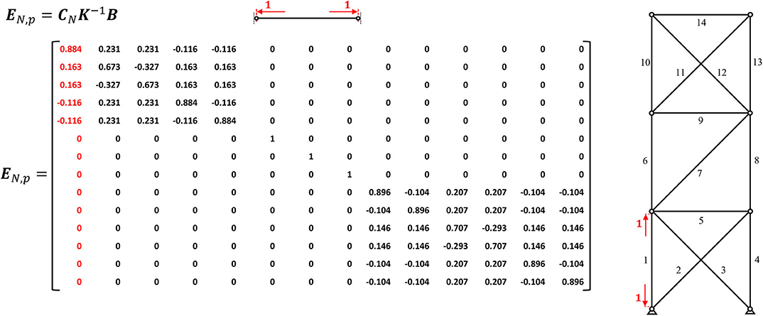
Figure 3. Influence matrix of axial forces due to parallel linear actuation EN, p of an exemplary truss.
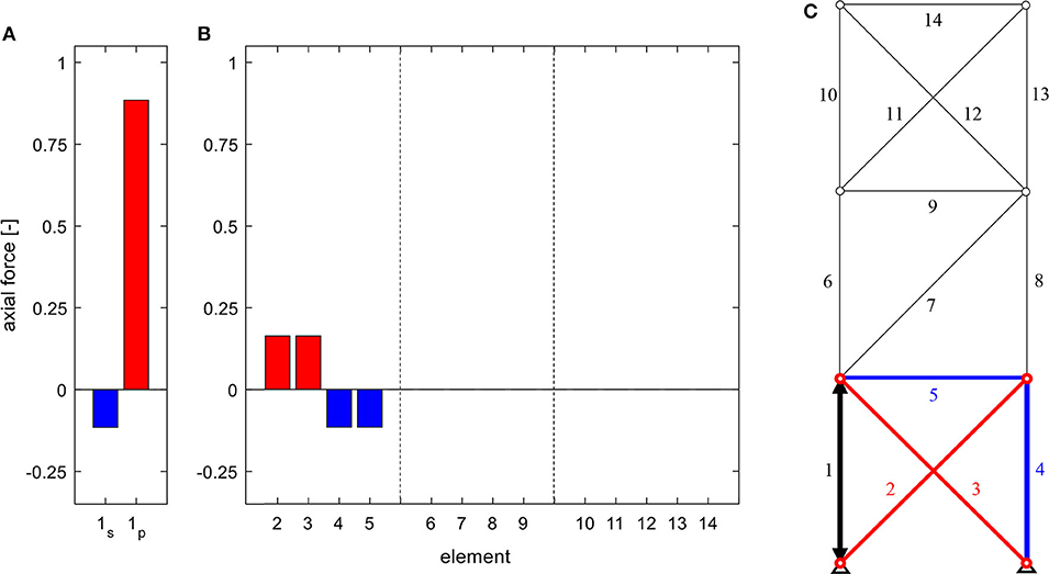
Figure 4. Axial forces in (A) the actuated element for serial (index s) and parallel (index p) linear actuation, (B) the remaining structure due to the actuation of element 1 (C), for a truss of the static degree of indeterminacy of ns = 2.
Statically Indeterminate Truss—Homogenous Stiffness Distribution
For the first variation, a second diagonal is added to the middle module (cf. Figure 5), thus changing the substructure's static determinacy from determinate to indeterminate and increasing the overall degree of static indeterminacy ns to three, which corresponds to the rank of the influence matrix of axial forces due to serial linear actuation EN, s for this system. Changing from statically determinate to indeterminate means constraining the substructure, disabling it from deforming freely and enabling an additional state of axial forces of the middle module, which can be manipulated.
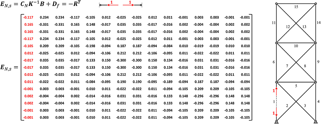
Figure 5. Influence matrix of axial forces due to serial linear actuation EN, p of an exemplary truss of the static degree of indeterminacy of ns = 3.
Thus, the separation of substructures (cf. Figure 2) is removed—the influence matrix is filled with non-zero values (see Figure 5). Actuation of an element in a neighboring substructure also affects the axial forces in the adjacent module (cf. Figure 6). However, in the given configuration of the load-bearing structure with homogenous stiffness distribution, the constraint can be compensated along two substructures, leading to negligible axial forces in the top module. Statically determinate substructures, as described in Statically Determinate Substructure, completely isolate the influence area of force actuation on chosen elements or substructures.
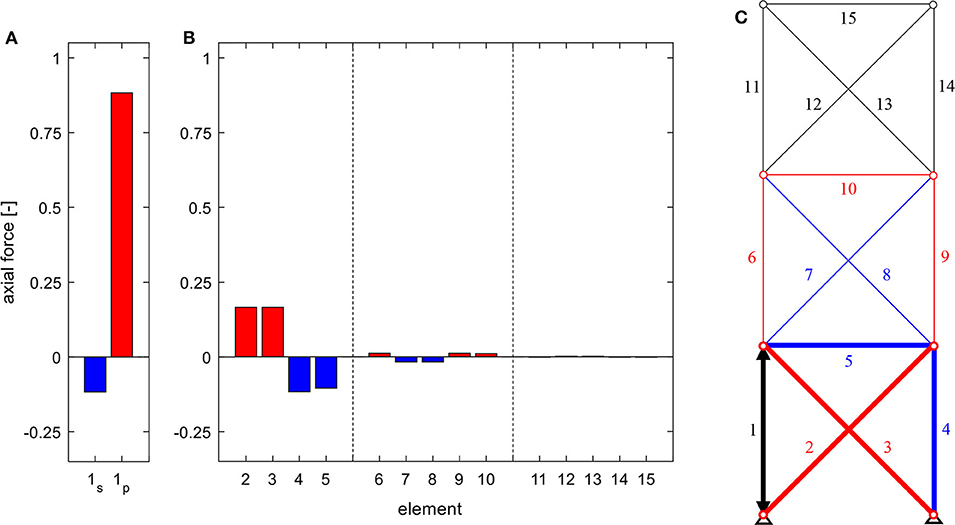
Figure 6. Axial forces in (A) the actuated element for serial (index s) and parallel (index p) linear actuation, (B) the remaining structure due to the actuation of element 1 (C), for a truss of the static degree of indeterminacy of ns = 3.
Statically Indeterminate Truss—Rigid Joints
Next, the pinned joints are exchanged for rigid connections (cf. Figure 7). As a two-dimensional load-bearing structure, the degree of static indeterminacy is increased from 3 to 27, meaning there are now 27 linearly independent states of the internal force variables (combined states of axial forces, shear forces, and bending moments), but only 15 elements available for linear actuation. The imposed constrained of the rigid joints, however, is very similar to that of the pinned connections in Figure 6, as the chosen quadratic cross-section is comparably flexible (cf. Table 1). The result is an almost identical state of axial forces, although shear forces and bending moments are also manipulated. Changing the stiffness of all elements equally, for example by choosing a material with a different Young's modulus, would have the same effect. Changing the shape of the cross-section to one with the same cross-sectional area, but with a higher area moment of inertia (I = 5.34e−4 m4) and therefore increasing the ratio of flexural stiffness to axial stiffness, would constrain the deformations differently, thus resulting in different states of internal variables (cf. Figure 8).
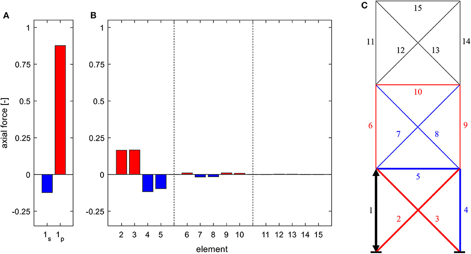
Figure 7. Axial forces in (A) the actuated element for serial (index s) and parallel (index p) linear actuation, (B) the remaining structure due to the actuation of element 1 (C), for a truss with rigid joints.
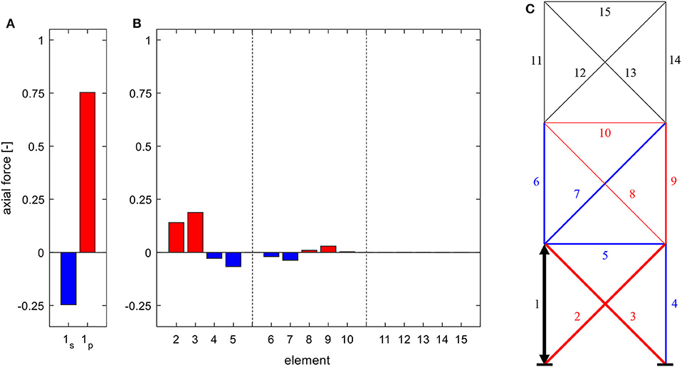
Figure 8. Axial forces in (A) the actuated element for serial (index s) and parallel (index p) linear actuation, (B) the remaining structure due to the actuation of element 1 (C), for a truss with rigid joints and beams with increased flexural rigidity.
While the overall stiffness of the structure is increased through the rigid joints, the stiffness distribution within the structure ist still homogenous. Therefore, as in Statically Indeterminate Truss—Homogenous Stiffness Distribution, the resulting constraint forces from an actuation in the bottom module can still be compensated along the lower two modules, disabling the manipulation of forces or bending moments in the top module.
Statically Indeterminate Truss—Varied Stiffness Distribution
Using the truss with pinned joints in Statically Indeterminate Truss—Homogenous Stiffness Distribution as base, the stiffness of all diagonals is now increased by a factor of 10 (cf. Table 1).
Increasing the stiffness of the diagonals increases, in turn, the constraint on the actuated column in Figure 9, resulting in an amplified state of axial forces due to actuation in the bottom module. As the diagonals in both upper substructures are also stiffened, their imposed constraint increases as well, in relation to that of the columns and cross girder. This leads to a further distribution of the influence of actuation. However, there are still only three linearly independent states of axial forces, as the static indeterminacy remains at ns = 3. The increased constraint also shows in the resulting axial forces in the actuated element of this variation (cf. Figure 7A). In the case of serial actuation, the actuated element experiences a larger compressive force due to the increased constraint described above. In the case of parallel actuation, however, the resulting tensile force is decreased, in comparison to previous system variations. The effect of short circuiting when using parallel actuation, which was prevalent before, is now less dominant, as the ratio of constraint imposed by the parallel passive element and the remaining connected load-bearing structure shifted toward the latter.

Figure 9. Axial forces in (A) the actuated element for serial (index s) and parallel (index p) linear actuation, (B) the remaining structure due to the actuation of element 1 (C), for a truss of the static degree of indeterminacy of ns = 3 and diagonals with increased stiffness.
Increasing the stiffness of each module from bottom to top, each by a factor of 10, also expands the influence of actuation of axial forces (resp. internal force variables) for actuators in the bottom module (cf. Figure 10). Although the constraint forces from actuation can still be (partially) compensated along each substructure, the increasing stiffness of each module results in higher axial forces.
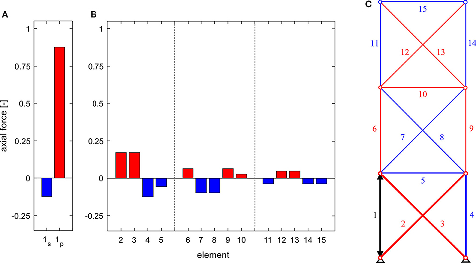
Figure 10. Axial forces in (A) the actuated element for serial (index s) and parallel (index p) linear actuation, (B) the remaining structure due to the actuation of element 1 (C), for a truss of the static degree of indeterminacy of ns = 3 and with modules of increased stiffness bottom to top.
Inverting the stiffness distribution, however, encourages a short circuiting of the actuation forces in the bottom module (cf. Figure 11). The induced constraint can be fully compensated, similarly to the system in Statically Determinate Substructure. The difference being, that, in this case, the influence of actuation of an element in the top module would still extend to the bottom module (equivalent to configuration in Figure 10). Careful placement of comparatively stiff elements or substructures in statically indeterminate systems can thus be used to control the area of influence of actuation forces, to create unilateral expansion of the influence, and to isolate the influence of actuation to certain substructures.
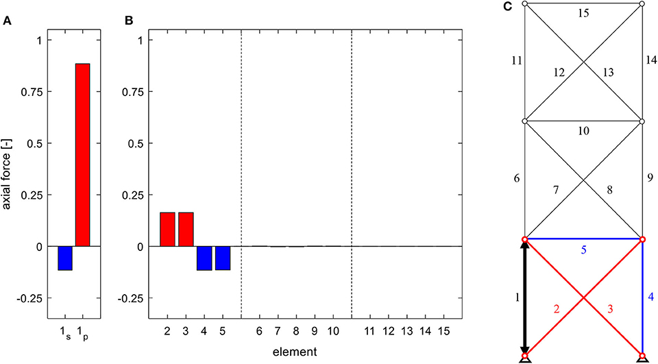
Figure 11. Axial forces in (A) the actuated element for serial (index s) and parallel (index p) linear actuation, (B) the remaining structure due to the actuation of element 1 (C), for a truss of the static degree of indeterminacy of ns = 3 and with modules of decreased stiffness bottom to top.
Module-Overlapping Structural Elements
Lastly, two diagonal bracings of the lower two modules (one of each) are replaced by one overlapping bracing (Figure 12). Cross-sections and Young's moduli are reset to the initial values (Table 1). In this configuration, the axial force, which is induced by actuation of element 1, cannot be short circuited inside the bottom module, due to the elimination of the diagonal. The force is distributed into the structure along elements 4, 6, and 7, before it can be short circuited, respectively transferred to the supports through elements 2 and 7, the result being an even distribution of axial forces in both subsystems. Conversely, forces from actuation of element 3 would be primarily short circuited and transferred to the support through element 2, resulting in only negligible forces in the middle module. The overlapping diagonal merges two statically determinate substructures to one statically indeterminate module. This configuration is also comparatively flexible, as the resulting axial forces through linear actuation are relatively small and the force from parallel linear actuation is nearly fully short circuited along the parallel passive element. The top module, again, is connected comparably flexible, resulting in minimal axial forces.
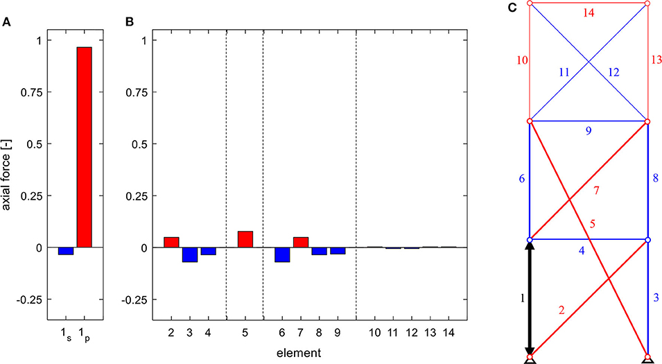
Figure 12. Axial forces in (A) the actuated element for serial (index s) and parallel (index p) linear actuation, (B) the remaining structure due to the actuation of element 1 (C), for a truss with module-overlapping bracing.
Overlapping elements can therefore be used to connect individual modules, allowing for a further distribution of the influence of actuation. Likewise, removing or adding certain elements from, respectively, to a structure controls the possible load paths, which are activated through actuation.
Result Discussion and Generalization
Through actuation, an actuator performs a motion, e.g., extension or retraction in case of linear actuators. If this motion can be performed freely, no internal force variables, e.g., axial forces, can be manipulated; only rigid body motions can be induced. If the motion is constrained, internal force variables, i.e., actuation forces, are activated, leading to deformations (and rigid body motions). The load-bearing structure is statically indeterminate. The degree of static indeterminacy corresponds to the number of linearly independent states of internal force variables, which can be manipulated through actuation. Placing serial actuators into a substructure of an ideal truss, in a number greater its static (in)determinacy, allows for constraint free rigid body motions. In the case of beam structures, it is not necessarily possible to actuate all states by linear actuators alone. The forces and moments induced by actuation have to be transferred to the supports or short circuited inside the load-bearing structure. These load paths—and therefore the sphere of influence—can be controlled by the topology, meaning the configuration of elements, the stiffness distribution, and the static (in)determinacy. For example, strategically placing statically determinate substructures or indeterminate modules with reduced stiffness limits the sphere of influence, while overlapping elements or elements with comparatively higher stiffness can be used to further distribute the influence of actuation. Parallel actuation always generates a linearly independent state of internal force variables, due to the parallel connection of the actuator to the passive element, which also inverts the resulting force in the parallel passive element compared to the actuation force. These basic principles underlie the algorithms listed in Introduction. Applying them directly in the design process of adaptive load-bearing structures should therefore result in adaptive topologies (resp. typologies) with increased resource and emission efficiency. Influence matrices can be used for additional analysis, for example to quantify the effects of actuation, allowing the designer to further optimize their load-bearing structure in regards of its adaptability. The method is presumed most effective in the early conception phase of load-bearing structures and on smaller (sub)systems with a limited number of structural elements.
Large-Scale Prototype High Rise
The method of influence matrices was developed during the interdisciplinary design process of a large-scale adaptive high-rise prototype, which is currently being realized on an experimental platform at the University of Stuttgart. Upon its completion, it will be the world's largest adaptive structure with a total height of 36 m, consisting of 12 identical floors, which are separated into four similar units (Weidner et al., 2018). Eight hydraulic cylinders are implemented as parallel actuators in the columns of unit 1 and 2 and a further 16 serially incorporated hydraulic actuators in the structure's diagonal bracing (eight in unit 1, and four in each unit 2 and 3) complete the actuator placement. Movements and changes in the stress state of the structure are tracked by a multitude of strain gauges, inertial measurement units (IMUs), and 16 LED tracking sensors. Oscillation of the tower through wind is calculated to reach a deflection of maximum 30 mm at the topmost point. Through actuation, deflections of up to 140 mm become possible. The whole building will be subject of investigation for multiple research projects, throughout its lifetime. One focus of its conception, therefore, lies on the adaptability of the structure and the exchangeability of structural (and façade-) elements. This enables a comfortable dismantling process and also the possibility of removing structural elements and replacing them with elements of different materials or new actuation concepts, which result from the ongoing and upcoming research in the Collaborative Research Centre 1244 Adaptive Skins and Structures for the Built Environment of Tomorrow, allowing for large-scale tests of different configuration of the 12-story experimental high-rise building, according to the findings of different methods, such as the influence matrices. The concepts for actuation introduced above have been experimentally tested and validated in a prototype frame and published in Weidner et al. (2019).
Conclusion
In this paper, a general method of influence matrices is derived and specified for the case of axial forces for serial and parallel linear actuations. Influence matrices are a type of sensitivity matrices, which underlie most optimization algorithms that search for the optimal actuator placement in a given load-bearing structure. Influence matrices quantify how a chosen actuation principle affects certain properties of the structure, respectively how changes in the topology of the structure affect the influence of the actuation, i.e., its adaptability. This is exemplified through studies of different configurations of an exemplary truss structure. Such an analysis indicates how the topology of adaptive load-bearing structures should be changed and where to implement which actuation principle in order to increase the adaptability of the structure and thus improve resource and energy efficiency. Future work will include further development and discussion of the presented method of influence matrices (e.g., combination of multiple elements into one actuation unit), the derivation and analyses of further actuation principles, the large-scale experimental validation of the actuation principles and presented findings through tests on the introduced experimental high-rise building, and the conception of adaptive structural typologies based on the presented findings.
Data Availability Statement
The datasets generated for this study are available on request to the corresponding author.
Author Contributions
WS initiated the research project, including the planning of the experimental high rise, whose design process SW coordinated. SW and SS also contributed in the planning phase of the high-rise, throughout which, under guidance of WS and LB, the presented method was developed. The first draft was written by SS and SW, with the former focusing on the presented method and the latter on the presentation of the experimental high rise. All authors contributed to the article and approved the submitted version.
Funding
The authors gratefully acknowledge the generous funding of this work by the German Research Foundation (DFG–Deutsche Forschungsgemeinschaft) as part of the Collaborative Research Centre 1244 (SFB) Adaptive Skins and Structures for the Built Environment of Tomorrow/project A06 and Z01 (Project number: 279064222).
Conflict of Interest
The authors declare that the research was conducted in the absence of any commercial or financial relationships that could be construed as a potential conflict of interest.
References
Böhm, M., Wagner, J., Steffen, S., Sobek, W., and Sawodny, O. (2019). “Homogenizability of element utilization in adaptive structures,” in 2019 IEEE 15th International Conference on Automation Science and Engineering (CASE) (Vancouver, BC, Canada: IEEE), 1263–1268. doi: 10.1109/COASE.2019.8843066
Holnicki-Szulc, J., Mackiewicz, A., and Kolakowski, P. (1998). Design of adaptive structures for improved load capacity. AIAA J. 36, 471–476. doi: 10.2514/2.388
Issa, J., Mukherjee, R., and Shaw, S. W. (2010). Vibration suppression in structures using cable actuators. J. Vib. Acoust. 132:031006. doi: 10.1115/1.4000783
Kelleter, C., Burghardt, T., Binz, H., Blandini, L., and Sobek, W. (2020). Adaptive concrete beams equipped with integrated fluidic actuators. Front. Built Environ. 6:91. doi: 10.3389/fbuil.2020.00091
Neuhaeuser, S., Weickgenannt, M., Witte, C., Haase, W., Sawodny, O., and Sobek, W. (2013). Stuttgart smartshell–a full scale prototype of an adaptive shell structure. J. Int. Assoc. Shell Spat. Struct. 54, 259–270.
Patnaik, S. (1973). An integrated force method for discrete analysis. Int. J. Numer. Methods Eng. 6, 237–251. doi: 10.1002/nme.1620060209
Peduzzi, P. (2014). Sand, Rarer Than One Thinks. Sioux Falls, SD: UNEP Global Environmental Alert Service (GEAP).
Penrose, R. (1955). A generalized inverse for matrices. Math. Proc. Camb. Philos. Soc. 51, 406–413. doi: 10.1017/S0305004100030401
Reinhorn, A. M., Soong Lin Rileay, M. A., Wang, Y. P., Aizawa, et al. (1992). Active Bracing System: A Full Scale Implementation of Active Control. Buffalo, NY: National Center for Earthquake Research (NCEER).
Reksowardojo, A. P., Senatore, G., and Smith, I. F. C. (2019). Experimental testing of a small-scale truss beam that adapts to loads through large shape changes. Front. Built Environ. 5:93. doi: 10.3389/fbuil.2019.00093
Reksowardojo, A. P., Senatore, G., and Smith, I. F. C. (2020). Design of structures that adapt to loads through large shape changes. J. Struct. Eng. 146:04020068. doi: 10.1061/(ASCE)ST.1943-541X.0002604
Schlegl, F., Honold, C., Leistner, S., Albrecht, S., Roth, D., Leistner, P., et al. (2019). Integration of LCA in the planning phases of adaptive buildings. Sustainability 11:4299. doi: 10.3390/su11164299
Scrivener, K. L., John, V. M., and Gartner, E. M. (2018). Eco-efficient cements: potential economically viable solutions for a low-CO2 cement-based materials industry. Cem. Concr. Res. 114, 2–26. doi: 10.1016/j.cemconres.2018.03.015
Senatore, G., Duffour, P., and Winslow, P. (2018a). Energy and cost assessment of adaptive structures: case studies. J. Struct. Eng. 144:04018107. doi: 10.1061/(ASCE)ST.1943-541X.0002075
Senatore, G., Duffour, P., and Winslow, P. (2018b). Exploring the application domain of adaptive structures. Eng. Struct. 167, 608–628. doi: 10.1016/j.engstruct.2018.03.057
Senatore, G., Duffour, P., and Winslow, P. (2019). Synthesis of minimum energy adaptive structures. Struct. Multidiscip. Optim. 60, 849–877. doi: 10.1007/s00158-019-02224-8
Senatore, G., Duffour, P., Winslow, P., and Wise, C. (2018c). Shape control and whole-life energy assessment of an ‘infinitely stiff' prototype adaptive structure. Smart Mater. Struct. 27, 015022. doi: 10.1088/1361-665X/aa8cb8
Sobek, W. (2016). Ultra-lightweight construction. Int. J. Space Struct. 31, 74–80. doi: 10.1177/0266351116643246
Sobek, W., and Teuffel, P. (2001). “Adaptive systems in architecture and structural engineering,” in Proceedings of SPIE–The International Society for Optical Engineering, ed S. C. Liu (Newport Beach, CA), 36–45. doi: 10.1117/12.434141
Sobek, W., Teuffel, P., Weilandt, A., and Lemaitre, C. (2006). “Adaptive and lightweight,” in Adaptables 2006: Proceedings of the Joint CIB, Tensinet, IASS international Conference on Adaptability in Design and Construction, Vol. 2 (Eindhoven: Eindhoven University of Technology), 6.38–6.42.
Sobek, W., Teuffel, P., and Landauer, A. (2002). Stuttgarter Träger. Stuttgart: Inst. Für Leichtbau Entwerf. Konstr. Univ. Stuttg.
Soong, T. T., and Manolis, G. D. (1987). Active structures. J. Struct. Eng. 113, 2290–2302. doi: 10.1061/(ASCE)0733-9445(1987)113:11(2290)
Ströbel, D. (1996). Die Anwendung der Ausgleichsrechnung auf Elastomechanische Systeme. Stuttgart: University of Stuttgart.
Teuffel, P. (2004). Entwerfen Adaptiver Strukturen. Stuttgart: University of Stuttgart. doi: 10.18419/opus-195
UNEP (2011). Decoupling Natural Resource Use and Environmental Impacts From Economic Growth. Nairobi: UNEP.
United Nations Environment Programme (2019). The Emissions Gap Report 2019. Available online at: https://www.unenvironment.org/resources/emissions-gap-report-2019 (accessed February 13, 2020).
Wagner, J. L., Gade, J., Heidingsfeld, M., Geiger, F., von Scheven, M., Böhm, M., et al. (2018). On steady-state disturbance compensability for actuator placement in adaptive structures. Automation 66, 591–603. doi: 10.1515/auto-2017-0099
Weidner, S., Kelleter, C., Sternberg, P., Haase, W., Geiger, F., Burghardt, T., et al. (2018). The implementation of adaptive elements into an experimental high-rise building. Steel Constr. 11, 109–117. doi: 10.1002/stco.201810019
Keywords: adaptivity, actuator placement, typology, optimization, finite element method, sensitivity, influence matrices
Citation: Steffen S, Weidner S, Blandini L and Sobek W (2020) Using Influence Matrices as a Design and Analysis Tool for Adaptive Truss and Beam Structures. Front. Built Environ. 6:83. doi: 10.3389/fbuil.2020.00083
Received: 28 February 2020; Accepted: 06 May 2020;
Published: 23 June 2020.
Edited by:
Gennaro Senatore, École Polytechnique Fédérale de Lausanne, SwitzerlandReviewed by:
Ehsan Noroozinejad Farsangi, Graduate University of Advanced Technology, IranMichele Betti, University of Florence, Italy
Copyright © 2020 Steffen, Weidner, Blandini and Sobek. This is an open-access article distributed under the terms of the Creative Commons Attribution License (CC BY). The use, distribution or reproduction in other forums is permitted, provided the original author(s) and the copyright owner(s) are credited and that the original publication in this journal is cited, in accordance with accepted academic practice. No use, distribution or reproduction is permitted which does not comply with these terms.
*Correspondence: Simon Steffen, c2ltb24uc3RlZmZlbkBpbGVrLnVuaS1zdHV0dGdhcnQuZGU=