 Sarah A. Stevenson
 Gregory A. Kopp
 Ayman M. El Ansary
- 1Boundary Layer Wind Tunnel Laboratory, Faculty of Engineering, University of Western Ontario, London, ON, Canada
- 2Department of Civil and Environmental Engineering, University of Western Ontario, London, ON, Canada
High-wind events cause significant damage to structures and property; in particular, light-frame wood homes are especially vulnerable and are the most abundant housing type in North America. As with many regions, Canadian homes are built to prescriptive standards that are based on historical construction methods and have remained relatively unchanged structurally across several decades, even though energy requirements have changed substantially. The present work reviews existing recommendations and campaigns for wind resilience in other jurisdictions, assesses their relevance to the Canadian context, and evaluates current construction methods as well as proposed improvement alternatives. Components that are commonly observed to fail in Canadian tornado damage surveys are of primary interest; namely, roof sheathing, roof-to-wall connections, and discontinuities in wall-to-floor links. Limit states design-based calculations are completed to assess the adequacy of nailed components from an engineering design standpoint. Past work quantifying the inadequacy of roof sheathing provisions in the current version of the National Building Code of Canada is discussed, and new analyses are done for the other components. Sources of conservatism in design calculations are identified, and unfactored results are provided to describe more representative limit states. When the redundancy of load and resistance factors is removed, the results show that current prescriptive provisions for roof-to-wall fasteners are likely to be sufficient up to a failure wind pressure of about 0.6 kPa—this applies to most regions in Canada. The wall capacity calculations suggest significant vulnerability to uplift or sliding withdrawal of nailed connections; however, these results are considered to be especially conservative. Potential, non-structural sources of house capacity are discussed. In general, current prescriptive provisions are deemed suitable for the synoptic wind events that they are expected to face. However, concern is identified for houses in open terrain or those prone to tornado risk. Design recommendations are presented in the context of providing resistance to up to EF2 tornadoes.
Introduction
In recent years, significant research efforts have contributed to mitigating loss of homes during extreme wind events such as hurricanes and tornadoes. Several local programs have encouraged better building practices, with the primary focus of keeping roof systems on residential structures intact. Small-scale incentive programs for builders who install strengthening measures such as hurricane clips have seen success in some municipalities in Canada. In the United States, the City of Moore, Oklahoma successfully developed a new building code designed to ensure houses withstand structural damage rated up to EF2 (Ramseyer et al., 2016). The new building code was unanimously supported by the Moore city council in 2014, 1 year after the third violent tornado (1-EF4 and 2-F/EF5) since 1999 hit the city. On May 20, 2013, 24 people were killed by an EF5 tornado that swept through Moore, including 7 children who died when an elementary school wall collapsed onto them. The loss of lives in this event is cited as the driving force for the creation of the new building code.
Although a devastating event such as the Moore tornado of 2013—or locally, the Ottawa, Ontario outbreak on September 21, 2018—has shown to initiate public interest in the issue of tornado resilience, it should not take such loss to influence isolated efforts toward resilient construction. Knowledge now exists to instigate mitigation measures across North America before the next devastating events occur. In Canada, research has enabled a better understanding of the extreme wind risks present across the country, and a vast database of damage survey data has been amassed for use in identifying common structural details that require strengthening.
While recent research has provided recommendations for improving some building components that are commonly observed to fail, such as the roof sheathing and roof-to-wall connections (RTWC) (Gavanski et al., 2014; Morrison et al., 2014), these recommendations have not been implemented into the building code of any province. Furthermore, many additional failure modes have been noted but are not sufficiently analyzed in post-storm damage investigations. These modes include failure of the roof framing members (Stevenson et al., 2018, 2019) and variations of wall removal and collapse. The complete set of prescriptive design provisions in Part 9 of the National Building Code of Canada (NBCC) (Canadian Commission on Building and Fire Codes, 2015) has not been evaluated against realistic wind loads.
National Building Code of Canada Wind Provisions
Early forensic studies following tornadoes in Canada found that a large majority of tornado deaths occurred in buildings that either lacked anchorage of the floor to the foundation or of the roof to the walls (Allen, 1984, 1986; Carter et al., 1989; Newark, 1991). Allen (1984, 1986) suggested that proper anchorage should be required after significant injury and death were caused by cottages and their occupants being swept into the Blue Sea Lake, Quebec in 1984. The Barrie, Ontario tornado outbreak in 1985 reiterated the importance of proper building anchorage. The field proof provided by these studies resulted in an update to the 1995 release of the NBCC, which then included requirements for wood-frame buildings to be anchored to their foundations. A commentary on the best practices for structural resilience in “tornado-prone” regions was also provided. These recommendations have remained unchanged since their introduction and can be found in Commentary I of the NBCC Part 4 user's guide (Canadian Commission on Building Fire Codes, 2017).
Until recently, tornado-prone regions in Canada have not been well-defined. Between 1980 and 2009, it was estimated that ≈60 tornadoes occurred in Canada each year (Environment Canada, 2018). However, meteorologists acknowledged that many tornadoes are likely to occur in remote regions and go unreported. In recent research (Sills et al., 2012; Cheng et al., 2013), statistical analyses of radar observations and lightning strike data have suggested that the true tornado occurrence in Canada may be as high as 230 per year. Based on this work, the regions expected to face tornado risks are shown with the historical tornado occurrence data in Figure 1. As shown, many of Canada's largest urban areas exist within the regions prone to EF2-EF5 tornadoes.
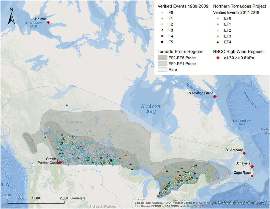
Figure 1. Map showing historical tornado record (Environment Canada, 2018), recent confirmed events (Northern Tornadoes Project, 2020), tornado-prone regions as defined by Sills et al. (2012), and locations considered by the NBCC (Canadian Commission on Building and Fire Codes, 2015) to face high wind risk.
Wind risk is currently addressed in the prescriptive design provisions of the National Building Code of Canada based on regional 1-in-50-year hourly wind pressures (q1/50). In regions where 0.8 kPa ≤ q1/50 < 1.2 kPa, moderate wind risk reduction measures—including improved fastening of roof sheathing, roof-to-wall fasteners capable of withstanding 3 kN uplift, and braced wall panels to resist lateral loading—are required. Buildings must be fully engineered where q1/50 ≥ 1.2 kPa. As labeled in Figure 1, the 0.8 kPa threshold wind pressure is met in 6 communities across the country, which have a combined population of less than 10,000 people (Statistics Canada, 2018). The 1.2 kPa threshold is met on Resolution Island, Nunavut, which is uninhabited. Normal design provisions apply to all other regions—virtually all of Canada.
The vast majority of tornado-prone land does not fall within the regions identified by the NBCC to experience elevated wind risks. Further population growth in these regions will only increase the likelihood of tornadoes impacting cities, communities, or homesteads. The present work assesses whether the Normal design provisions in the NBCC are sufficient for the range of wind loads that they are intended to withstand (q1/50 up to 0.8 kPa). Expected tornado resistance can be inferred from the same findings.
Since the 1995 edition of the NBCC, a section addressing tornadoes is provided in the supplementary structural commentaries document. Despite acknowledging that “tornadoes account for the greatest incidence of death and serious injury of building occupants due to structural failure…” the commentary qualifies that it is generally not economical to design buildings for tornadoes beyond current wind provisions (Canadian Commission on Building Fire Codes, 2017). Two “key details” are suggested as voluntary considerations for tornado resilient designs; “the anchorage of house floors into the foundation or ground,” and “the anchorage of roofs down through concrete block walls.” Sufficient foundation anchorage is now provided in the normal prescriptive provisions for houses through embedded steel anchor bolts. The second detail is not examined herein since masonry block load-bearing walls are rare in contemporary residential construction. Finally, the commentary states that other key elements should be designed to withstand the effects of 2 kPa uplift on the roof, 1 kPa pressure on windward walls, and 2 kPa suction on leeward walls.
While building anchorage and roof-to-wall connections are addressed to some extent in the NBCC (Canadian Commission on Building and Fire Codes, 2015) Part 9 provisions, they may be insufficient considering the limited number of regions where high-wind resistance is required. In addition, there are other potential weak links in residential structures that have been identified in post-storm forensic surveys but are neglected in typical design. For example, the wall-to-floor connection detail, which is adjacent to the building anchorage, requires a minimum of one nail spaced at 400 mm. This and other potential weak links will be discussed in the following sections.
Continuous Load Path
A house that is well-constructed to withstand wind risk has its structural systems tied together, from the roof structure to the foundation, and is fastened securely to the foundation. It also includes lateral force resisting measures to prevent horizontal movement or racking, and well-secured cladding components to preserve the building envelope and prevent water intrusion. While recent research has provided recommendations for improving some building components that are commonly observed to fail, such as the roof sheathing and the roof-to-wall connection (RTWC) (Gavanski et al., 2014; Morrison et al., 2014), these recommendations have not been implemented into the building code in any province. Further, several additional shortcomings of contemporary house construction have been identified but have not been researched in detail. These potential modes include failure of the roof framing members (Stevenson et al., 2018, 2019) and variations of wall removal and collapse.
The current strategy for increasing performance of homes during high wind events is to design measures that contribute to a continuous vertical load path. The first load-transferring link in any structural system is the surface to which external forces are applied. In a conventional wood-frame residential structure, wind loads are applied to the exterior surfaces of the building envelope; the roof covering system consists of layers of cladding, water barrier, and wood sheathing panels, and the wall envelope consists of siding or veneer, insulation, and sometimes wood panels. In roofs, wind suction is transferred from the roof sheathing through its fasteners to the outer roof framing members. The next critical link in the transfer of uplift loads is the roof-to-wall connection—the fastener joining the roof structure (trusses or rafters and joists) to the top of the exterior walls. The walls must transfer both vertical and horizontal loads from the roof, through the floor structure and lower-story walls, into the foundation. Figure 2B shows a diagram of all common connections throughout the vertical load path, with the NBCC-required nailing labeled.
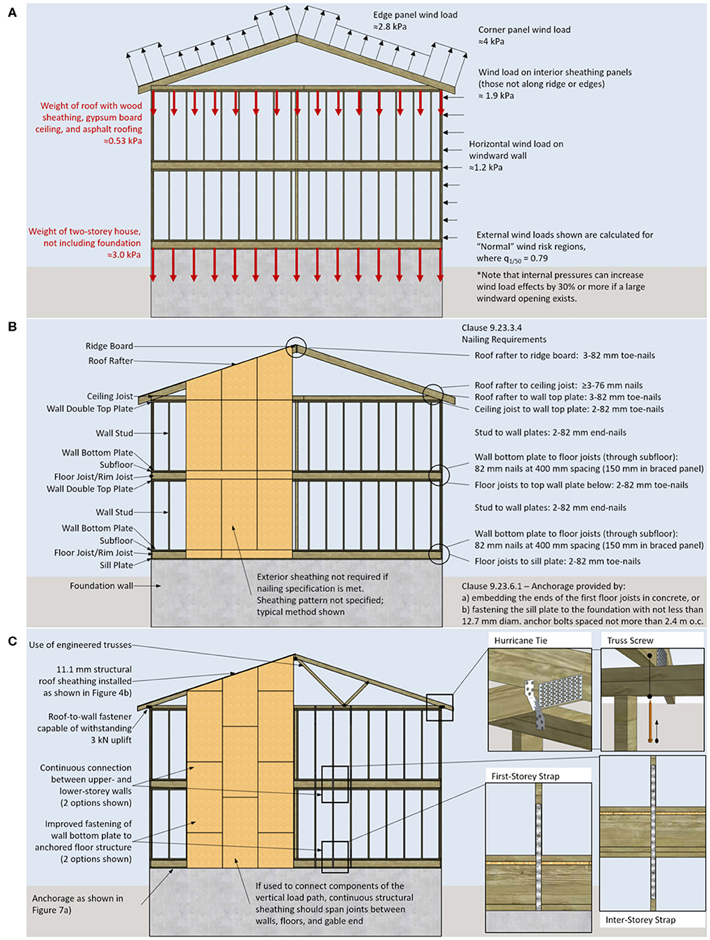
Figure 2. (A) Diagram of external wind load distribution used in the design of structural components and cladding, with estimated self-weight at the roof and ground levels shown for comparison, (B) Diagram showing an example design currently allowed by the NBCC (Canadian Commission on Building and Fire Codes, 2015), with element nomenclature and relevant clauses labeled, (C) Diagram with recommended design components, based on the recommendations in Sandink et al. (2018).
Gavanski et al. (2013) used wind tunnel experiments to evaluate the distribution of wind loads across roof sheathing panels on 67 configurations of residential roof shapes. Variations in roof shape, slope and height and surrounding terrain were considered to identify the worst-case configuration for wind uplift on roofs, and the distribution of the forces in these scenarios. The parameters most influencing external wind loads are the surrounding terrain and the shape of the roof (gable vs. hip). For gable roofs, the highest wind loads occur along the gable end roof edges. For hip roofs, critical zones shift depending on the slope of the roof, but hip roofs generally have lower external pressures than gable roofs. Figure 2A illustrates a gable roof with the code-specified distribution of external wind loads applied. Also shown are the expected dead loads due to the weight of the roof and wall structure, cladding, and insulation. The wind loads shown are calculated according to the NBCC (Canadian Commission on Building and Fire Codes, 2015) provisions in Part 4.1.7 for components and cladding in a region where the q1/50 = 0.79 kPa. This comparison shows that since the weight of light wood framing is relatively small, houses must rely on fasteners to hold components of the vertical load path together.
Fluctuating external pressures can lead to incremental failure of connections that initiate at wind pressures lower than the ultimate capacity (Guha and Kopp, 2014). In addition, houses are especially vulnerable to high internal pressures induced by wind entering window, door, or garage door openings (Ginger et al., 2007; Kopp et al., 2008; Morrison et al., 2012, 2014). Many of the components that close the openings in houses are weaker than the adjacent wall structure and may be blown in by high windward forces or breached by debris impact. The risk of breaches in the building envelope should be considered while assessing worst-case internal pressures and reducing wind-borne debris should be prioritized.
Several studies (Oh et al., 2007; Kopp et al., 2008; Morrison et al., 2014) have examined the effects of internal pressure in houses with typical opening layouts, as well as the effects of internal walls and partitioned living spaces. Morrison et al. (2014) provides a discussion of internal pressurization based on field damage observations, including a case study where neighboring houses displayed a large disparity in severity of damage due to internal pressurization of the worse-damaged house when its front door blew in. Oh et al. (2007) compared wind tunnel measurements to code-specified internal pressure coefficients and found that for most common opening shapes, the NBCC (1995 version) underestimates the effects of internal pressures.
The NBCC accounts for internal pressure in buildings requiring structural design by specifying maximum positive and negative internal pressure coefficients. Internal pressure coefficients are specified according to the distribution and relative size of openings in the building, and whether the openings are wind-resistant or likely to be open during storms. The worst-case combination of internal and external pressures (high internal pressure paired with high external suction) makes up the design wind load for engineered structures. In the prescriptive section of the NBCC (Canadian Commission on Building and Fire Codes, 2015), consideration for internal pressures is not explicit. The distribution of openings is not specified, nor is the quality of door or garage door hardware. As shown in the following sections, Part 9 designs [NBCC (Canadian Commission on Building and Fire Codes, 2015)] may not provide sufficient strength according to design checks following the Part 4 structural design requirements.
Previous Wind-Resilient Housing Campaigns
The development of the Moore, OK building code took an engineering design approach to strengthening houses (Simmons et al., 2015; Ramseyer et al., 2016). By increasing the design wind speed for the region from 90 to 135 mph, existing prescriptive details had to be re-evaluated. The revision resulted in the development of 12 new prescriptive provisions. The new provisions describe the features required to make wood-frame residential structures resist the new design level event. By increasing the design wind speed, the new Moore, OK building standard is intended to make residential structures withstand up to EF2 wind speeds with no structural failures.
Perhaps the most robust set of prescriptive recommendations currently used for strengthening residential structures against high wind and other natural hazards is the FORTIFIED Homes program (Insurance Institute for Business Home Safety, 2020), released by the Insurance Institute for Business & Home Safety (IBHS) in the United States. FORTIFIED standards provide guidance for hurricane- and high wind-prone regions separately, using a tiered approach to incrementally strengthen homes (Malik et al., 2012; Insurance Institute for Business Home Safety, 2015a,b). IBHS's full-scale, destructive testing facility and an extensive field research program (Standohar-Alfano et al., 2017) inform development of the recommendations in which the most commonly observed failure points are addressed first. The program is divided into three tiers with increasing design level, such that homeowners can elect to have the most effective improvements done first then incrementally improve their homes with time.
The FORTIFIED Homes program provides voluntary standards for homeowners who wish to build, or rebuild, their homes to withstand extreme weather. Although voluntary, the FORTIFIED Homes program is nationally recognized; some insurers offer discounts for homes that qualify for the FORTIFIED tiers, and a recent bill introduced to the US Senate would allow for up to $5,000 USD in tax incentives for houses that are built or retrofit to meet certain resilience levels, including qualification for the FORTIFIED tiers (Simmons, 2019; US Senate - Finance Committee, 2019). The FORTIFIED program provides a comprehensive basis for wind resilient construction or retrofit for houses built to common American practice. Many of the FORTIFIED recommendations are applicable to Canadian construction, although several require modification. Other sets of recommendations relevant to American homebuilding are published by industry members such as APA - The Engineered Wood Association (2018), or others with targeted industry interests. While these recommendations provide viable alternatives, one must be mindful of potential bias toward use of certain materials or proprietary products. A successful standard will allow homebuilders the choice to meet performance criteria by means of the most affordable and practicable solutions for their market.
In Canada, damage survey findings have led to investigation of the details of residential structures, proving the need for strengthening; however, without construction industry buy-in, they have not been implemented into national code changes. Several community-scale programs have been implemented to test installation, enforcement, and performance of wind-risk reduction measures in new homes. In 2012, the provincial building code of Ontario introduced a change requiring a reduction in spacing between roof sheathing fasteners (Ministry of Municipal Affairs and Housing, 2010). A pilot project is currently underway in collaboration between Western University, ICLR, and a local residential developer to implement wind-resilience measures in 100 new homes being constructed in St. Thomas, Ontario. Five different homebuilders are involved in the process, and ongoing work has collected feedback on the cost, ease of installation, and feasibility of measures recommended to strengthen the roof sheathing fastening, RTWCs, and gable overhang details.
Objectives
The objective of this work is to provide a critical assessment of current prescriptive design standards for wood-frame buildings, review and analyze the wind failure modes most commonly observed in field assessments, and introduce the basis for a new national standard of Canada for wind resilience of non-engineered residential structures. A report corresponding to this work has been published for use in ongoing standard development by the Canadian Standards Association (Sandink et al., 2018).
Based on existing research that is available for wood-frame houses in North America and the success of wind-resilience programs in other jurisdictions, the current recommendations target EF2 wind speeds as an appropriate design level. According to historical tornado records (Environment Canada, 2018), over 90% of tornado events in Canada have been EF2 or less. In addition, a gradient has been observed across the path of tornadoes such that, even in stronger events, much of the damage will be caused by less intense winds. The Moore building code (Ramseyer et al., 2016) justifies its design level event based on this gradient, and Amini and van de Lindt (2014) reiterate EF1 or EF2 wind speeds as feasible design targets. Although conventional homes are not expected to survive a direct hit from an EF4 event, nearby homes that avoid a direct hit may. In the Moore Oklahoma tornado of 2013, an example was identified where residential damage varied from EF5-severity to EF2 within 70 ft. The recommended measures aim to reduce vulnerability to the lower intensity tornadoes that primarily occur, while serving to mitigate the extent of damage caused by stronger events.
Failures of Residential Structures
Damage surveys following destructive wind events offer the opportunity to improve construction practice and understand the patterns in structural behavior under extreme winds. In addition, since it is not feasible to directly measure wind speeds in tornadoes due to their sporadic, highly localized, and intense nature, failures of common structures and vegetation are analyzed to estimate the bounds of probable wind speeds. The Enhanced Fujita Scale (Environment Canada, 2013) provides a standardized method for relating observed damage to estimated wind speed ranges. For discussion, it is often useful to present common residential failure modes in the context of EF-Scale damage ratings.
The current version of the Canadian EF-Scale provides wind speed estimates for 31 categories of common structures and vegetation, referred to as Damage Indicators (DIs). The estimated wind speeds at different failure levels for each DI were obtained through expert elicitation. For each DI, “Degrees of Damage” (DOD) are used to classify the sequential modes of damage based on historical descriptions of damage that have been observed to occur in structures of the DI's type. Each DOD is associated with a minimum, maximum, and expected wind speed. These values represent the estimated wind speeds required to cause the specified damage. They can be related back to the EF-Scale wind speeds to estimate the intensity of a tornado, from EF0 to EF5. Residential structures built to prescriptive standards fall under the DI for One- and Two-Family Residences (FR12). DOD descriptions and wind speed estimates are shown for this DI in Table 1.
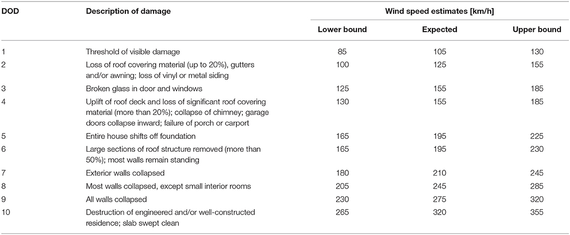
Table 1. DOD descriptions and wind speed estimates for single-family residential structures, as adopted by Environment Canada (2013).
It should be mentioned that tornado wind speeds in the EF-Scale represent 3-s gust wind speeds in open terrain at the height of failure and, therefore, cannot be directly compared to hourly mean wind speeds, on which the q1/50 design pressures in the NBCC (Canadian Commission on Building and Fire Codes, 2015) are based (Environment Canada, 2013; Morrison et al., 2014). However, a simple adjustment can be made (e.g., Durst, 1960) in order to identify the peak gust speeds implied by the hourly design wind speeds. Commentary C26.5.3 of ASCE 7-16 (Structural Engineering Institute, 2016) outlines the Durst procedure for adjusting wind speeds from hourly to 3-second gust wind speeds at 10 m. In Table 2, this method is applied to convert design wind pressures to equivalent 3-s gusts using a duration adjustment factor of 1.52. As shown, EF2 wind speeds correspond approximately to a target design pressure of 0.8 kPa.
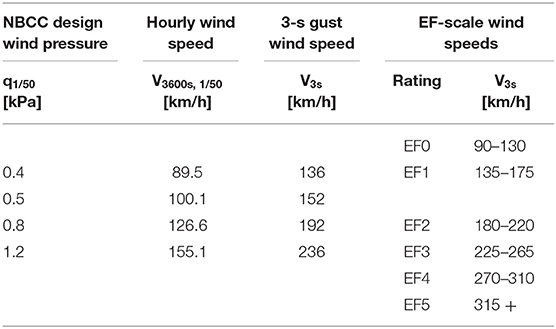
Table 2. Comparison of NBCC (Canadian Commission on Building and Fire Codes, 2015) design wind pressures with 3-s gust wind speeds as implemented in the EF-Scale (Environment Canada, 2013).
In addition, the current analysis for tornado wind loads assumes that the overall aerodynamic coefficients are not substantially altered, as argued by Kopp and Wu (2017), but that the loads should be treated like the building is in an open terrain with a uniform velocity profile below 10 m (Structural Engineering Institute, 2016). Wind loads in tornadoes are currently the subject of much research and, although the current analysis is discussed in terms of failure wind pressure, the target of designing to resist EF2 tornadoes, which was based on wind loads established in boundary layer wind tunnels, should be kept in mind.
Loss of Roof Sheathing
Roof sheathing is a critical element in residential structures because it supports the cladding components that protect the interior of houses from rain entry, and it helps connect adjacent roof framing members together so that they can share loads efficiently (Gavanski et al., 2014). Damage surveys and capacity analyses (Ellingwood et al., 2004; van de Lindt et al., 2007; Dao and van de Lindt, 2008; van de Lindt and Dao, 2009; Datin et al., 2011; Rocha et al., 2011; He and Hong, 2012; Henderson D. et al., 2013; Morrison et al., 2014; Kopp et al., 2017) have indicated that loss of roof sheathing panels can occur in relatively weak events. These failures can result in expensive damage or total loss of a house and its contents due to water entry (Sparks et al., 1994; Lee and Rosowsky, 2005) and they introduce debris into the wind field, increasing the risk to other structures (Reed et al., 1997; Masters et al., 2010).
As shown in Table 1, minor loss of roof sheathing corresponds with DOD4 and is estimated to occur at 155 km/h wind speeds, falling into the range for EF1 tornadoes (Environment Canada, 2013). It may be argued that DOD2 and DOD3 are both associated with roof vulnerability as well, since roof covering materials are likely to fail at relatively low wind speeds and enter the wind field as debris, posing risk to windows and doors (Gavanski and Kopp, 2017). According to historical data from Environment Canada (2018) and as shown in Figure 1, 90% of tornadoes are rated EF2 or less. Considering lower wind intensities that occur along the periphery of strong tornadoes, EF1 wind speeds account for a large amount of damage, although they occur far below the highest design level for houses (q1/50 ≤ 0.8 kPa ≈ 200 km/h 3-s gust), according to the NBCC (Canadian Commission on Building and Fire Codes, 2015). Figure 3 shows examples of DOD4 sheathing damage, corresponding to a tornado wind speed range of 130–185 km/h.
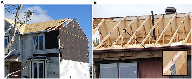
Figure 3. (A) DOD4 sheathing damage (B) Extensive DOD4 sheathing damage showing a magnified example of pull-through failure. Both photos were taken following the Dunrobin, Ontario tornado outbreak of Sept. 21, 2018.
A study by Henderson D. et al. (2013) examined the failure mechanisms of sheathing fasteners under realistic wind loads and compared a number of different fastener types. This work found that depending on the type of fastener, location on the panel, and stage in the failure progression, one of two failure modes may occur. One mode is pullout of the nail or staple from the lumber rafter or top chord member of the truss, and the other is rupture of the sheathing material such that the head of the fastener pulls through and remains embedded in the framing member. An example of the pull-through failure is shown in Figure 3B. An important finding of this work was that for both predominant mechanisms, failure of a panel initiated at an interior support, where the NBCC currently allows further spacing between fasteners.
Part 9 (Canadian Commission on Building and Fire Codes, 2015) specifies required sheathing thickness and materials, and fastener size and spacing for two wind risk categories. Nailing patterns for the “normal” wind risk regions (where q1/50 ≤ 0.8 kPa) are shown in Figure 4A. For oriented strand board (OSB) or plywood sheathing panels up to 10 mm thick, acceptable fasteners include 51 mm common or spiral nails, 45 mm ring shank nails or screws, or 38 mm staples. The spacing requirement is 150 mm along panel edges and 300 mm along intermediate supports. In higher wind risk regions, longer fasteners are required at the same spacing, except within 1 m of the roof edges, where 50 mm spacing is required.
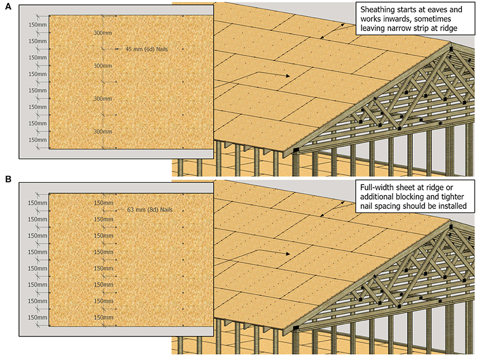
Figure 4. (A) Sheathing fastener requirements per NBCC part 9.23.3.5. (B) Recommended sheathing fasteners and panel placement considerations.
Gavanski et al. (2014) assessed the performance of the NBCC 2010 fastener specifications and compared them against alternative fastener types and spacing configurations using capacity data from several different experimental programs (Datin et al., 2011; Henderson D. et al., 2013; Gavanski et al., 2014). A reliability analysis was conducted to estimate the occurrence of sheathing panel loss at increasing wind risk levels. The analysis accounted for variations in wind speeds and terrain conditions across the country, measured fastener capacity, and house shape. Thirty-three different roof configurations were considered to capture the range of common roof shapes.
Gavanski et al.'s (2014) reliability results show that the sheathing fasteners specified in Part 9 do not meet the required performance level. Fastener designs that exceed a tolerable annual failure probability of 5*10−5 were considered inadequate, based on target reliability index of 3 for a 50-year service period (Bartlett et al., 2003). Under some conditions, 51 mm nails at 150/300 mm spacing are inadequate even below a threshold q1/50 of 0.4 kPa. This suggests that the fastener layout shown in Figure 4A may only be suitable in ~40% of the climate regions in Canada [NBCC (Canadian Commission on Building and Fire Codes, 2015)], as opposed to the 99% where it is currently approved.
Suggested changes to the building code in Gavanski et al. (2014) include modifying the lower wind design threshold to q1/50 ≤ 0.4 kPa and requiring longer nails (63 mm) at 150 mm spacing on edge and intermediate supports where 0.4 kPa < q1/50 ≤ 0.8 kPa, as shown in Figure 4B. Engineering guidance should be applied where q1/50 exceeds 0.8 kPa, but several adequate alternatives are identified in their study. Although these analyses were done as an assessment of the 2010 release of NBCC, no changes were implemented in NBCC (Canadian Commission on Building and Fire Codes, 2015) to address sheathing inadequacies, and no proposals exist in this regard for the 2020 release.
Major Roof Damage
Structural failures of residential roofs are evaluated under DOD6 for FR12 in the EF-Scale. These failures can correspond to a range of tornado wind speeds spanning from EF1 to EF3, evaluated based on observed construction quality and roof shape (Environment Canada, 2013). DOD6 failures commonly occur through uplift of large roof section due to failure of the roof-to-wall connections (RTWC). Traditionally, wood-framed roofs consist of pre-fabricated trusses or individual joist and rafter members (stick-framing) and are fastened to the supporting walls using toe-nails. Toe-nailed connections comprise nails driven through the face of the supported roof member at an angle into the wall top plate below. The NBCC (Canadian Commission on Building and Fire Codes, 2015) requires three, 82 mm long nails to be used at each RTWC for trusses. Figure 5 shows an example of failure of a RTWC built to this specification.
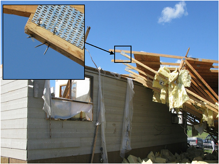
Figure 5. Failure of toe-nailed roof-to-wall connection from an F3 tornado that hit Raymore, SK in June 2010.
Toe-nailed RTWCs have been cited as the weak link in the vertical load path of houses in many post-storm damage assessments (Prevatt et al., 2011, 2013; Graettinger et al., 2014; Morrison et al., 2014; Kopp et al., 2017). Fragility analyses have even shown that in houses with certain roof shapes, RTWCs can fail at lower wind speeds than roof sheathing (Amini, 2012; van de Lindt et al., 2012; Kopp et al., 2017). This may explain the overlap in wind speeds for DOD4 and DOD6, shown in Table 1. DOD6 represents a more significant failure mode than DOD4. When part or all of the roof structure is removed, walls are more susceptible to collapse, debris poses a greater threat to neighboring structures, and life safety is at a greater risk.
Many studies have evaluated the performance of toe-nailed RTWC's (Reed et al., 1997; Riley and Sadek, 2003; Cheng, 2004; Morrison and Kopp, 2011; Morrison et al., 2012; Henderson D. J. et al., 2013), as well as presenting alternatives for improved RTWCs. One of the relatively early studies (Cheng, 2004) concluded that toe-nailed RTWCs are not sufficient for most wind zones in the US and recommended that metal ties be used. This has been re-iterated in several subsequent studies, although Canadian codes have not been addressed in a similar regard.
Morrison et al. (2012) tested a full-scale house to evaluate the performance of toe-nailed connections as parts of a complete structural system. The test house was designed to represent a typical, two-story house built to the NBCC prescriptive standard. The house plan dimensions were 9 m by 8.9 m, the eave height was 8 m, and it had a gable roof with a 4:12 slope. For consistency, design calculations discussed herein use the geometry of the same house.
In a concurrent study, Morrison and Kopp (2011) tested the capacity of toe-nailed connections under realistic, fluctuating wind loads, and converted the results to an equivalent design wind speed based on wind design equations from the ASCE 7-05 standard (Structural Engineering Institute, 2016). This calculation, based on the archetype house described above, showed that the most highly-loaded RTWC on the roof would likely fail during a design-level event in all wind risk regions in the US. Morrison and Kopp's (2011) test specimens included toe-nailed connections constructed with three nails, matching those specified in Table 9.23.3.1 in NBCC (Canadian Commission on Building and Fire Codes, 2015), as well as connections with missing nails to address a construction error that is commonly observed in failed roofs in the field.
Despite the vast body of research related to RTWCs, they have not been assessed in the context of Canadian design codes. To the authors' knowledge, the current prescriptive design provisions for RTWCs in Canada have not been evaluated against realistic wind loads, nor simplified design wind loads calculated per Part 4.1.7 of the NBCC (Canadian Commission on Building and Fire Codes, 2015). The following section presents a design check for common, toe-nailed RTWCs and compares the results to the expected performance of improved connections from the current recommendations.
Engineering Design of Roof-to-Wall Connections
For failure of a component to occur under wind uplift, the applied loading must exceed the combined effect of the material strength and the contribution of self-weight of the structure. This failure condition is expressed by the limit state equation;
where failure occurs when z ≤ 0, due to the imbalance where wind load (W) exceeds the combination of resistance (R) and dead load (D). In structural design, as governed by Part 4 of the NBCC (Canadian Commission on Building and Fire Codes, 2015), the limit state is the basis for design. Variabilities in loading, material properties, and those introduced by construction errors are accounted for in design standards by use of load and resistance factors. Load effects are overestimated by factors that have been calibrated to a desired reliability level. In Part 4, five possible load combinations are defined, based on the loads that are likely to act simultaneously [Clause 4.1.3.2; NBCC (Canadian Commission on Building and Fire Codes, 2015)]. In the load combination where wind poses the principal threat, W is increased by a factor of 1.4, and D is either increased by 1.25 or decreased 0.9, depending which option worsens the principal action. In the case of wind uplift, the self-weight of the structure counteracts the principal action, so the reduction is applied. Resistance of structural components and connections for wood structures is determined in accordance with the Canadian standard for design in wood (Canadian Standards Association, 2014), where the withdrawal resistance of a nail is reduced by a factor of 0.6, and further by 0.67 for toe-nailed connections (Clause 12.9.5). Additionally, the target reliability for wood structures is such that 5th-percentile component capacities are specified for design calculations.
The failure wind pressure (qfailure) for each connection type was calculated by balancing the limit states equation. The capacity of a range of connection types, obtained from CSA O86 (2014) code calculations, past studies (Morrison and Kopp, 2011), and manufacturers' specifications (Simpson Strong-Tie, 2018), are balanced with wind loads calculated based on the Part 4 wind load procedures for the Main Wind Force Resisting System (MWFRS), considering open terrain. MWFRS loads are calculated and applied instead of the method used in design of Components and Cladding (C&C) because of the expected effect of load sharing between members of the structural system. C&C loads apply large, isolated peaks to components and cladding elements that are expected to independently resist them, while MWFRS loads allow for peak loads to be dispersed across systems where the stiffness of neighboring members and the load distributing membrane allow for loads to be shared across larger tributary areas. This effect has been well-established for trussed roofs in previous studies (Gupta, 2005; Morrison et al., 2012; Henderson D. J. et al., 2013; Navaratnam, 2016) and is further discussed below. The house geometry from Morrison et al. (2012), who found load sharing across most of the roof, is considered in this analysis, and the wind uplift is evaluated including an internal pressure coefficient of 0.3, representing the case where openings are likely to remain closed during storms. The initial design calculations include all code-required load and resistance factors and are shown in Table 3 under the “Factored Design” heading. An example of the calculation approach for estimating the failure wind pressure for toe-nailed RTWCs is published as Supplementary Material to this paper.

Table 3. Design check for RTWCs showing factored and unfactored design wind pressures, as well as a comparison to the design wind pressures in NBCC (Canadian Commission on Building and Fire Codes, 2015) climate zones.
Limit states design for nailed connections under wind uplift is inherently subjected to a factor of safety of more than 2.3; the principal wind load is increased by a factor of 1.4, while fastener resistance is reduced by 0.6. The resisting dead load is also reduced by 0.9. For residential construction, the conservativism of Part 4 may be too demanding. Suggested targets for Part 9 structures are discussed in Critical Review of Building Code Provisions. Nominal failure wind pressures using the plain limit states equation, with no load or resistance factors, are also provided in Table 3 to enable discussion of less conservative, but perhaps more representative performance levels.
The resulting qfailure values are compared to the design wind pressures (q1/50) for all regions listed in the NBCC (Canadian Commission on Building and Fire Codes, 2015) climatic data tables. Where qfailure exceeds q1/50, this means that the component resistance exceeds the regional, 1-in-50 year demand; i.e., design is satisfied in that particular region. The number of regions in which design is satisfied for each connection type is also listed in Table 3. This comparison shows that according to factored limit states design, for an isolated house with scattered surroundings (open exposure), toe-nailed RTWCs are insufficient in every Canadian wind zone. In the nominal design values, the redundancies of load and resistance factors are removed. These results show that, even when considering the 5th-percentile capacity data from Morrison and Kopp (2011), toe-nailed connections only work up to a wind pressure of 0.503 kPa, corresponding to EF1 wind speeds. This wind pressure would correspond to a design-level EF1 tornado; however, since 5th-percentile capacity is considered in design equations, the present results represent worst-case combinations of aerodynamic loads and fastener capacity. Typically, discussion of EF-Scale wind speeds can be considered to be based on wind speeds at the median probability of failure, as determined by fragility analyses (Morrison et al., 2014; Gavanski and Kopp, 2017; Kopp et al., 2017; Roueche et al., 2017). The current results fall in the 5th-percentile range from the previous studies, and better represent the lower bound EF-Scale wind speeds.
An additional check was completed to compare the “high wind” requirement for RTWCs in Part 9 to the engineering design approach in Part 4. Clause 9.23.3.4, Sentence 3) requires a RTWC uplift capacity of 3 kN where q1/50 ≥ 0.8 kPa. The nominal design check shows that a 3 kN RTWC may only be sufficient up to q1/50 = 0.686 kPa. Other connection types considered include hurricane ties (H2.5A) and proprietary truss screws (6”), with capacities of 3.58 and 1.79 kN, respectively. Both products are defined based on resistance data published by Simpson Strong-Tie (2017, 2018). These values include the relevant load factors specified in CSA O86-14 (Canadian Standards Association, 2014); 0.8 for lateral failure of nails in hurricane ties and 0.6 for withdrawal of wood screws.
Although it may be argued that prescriptive designs should ensure resistance to worst-case loads, the reality is that the vast majority of Part 9 houses are constructed in suburban neighborhoods in close proximity to one another. For synoptic weather systems, the wind velocity near the ground—and therefore the wind pressure acting on a particular structure—is dependent on the surrounding terrain (St. Pierre et al., 2005; Gavanski et al., 2013; Gavanski and Kopp, 2017). The exposure factors specified in Clause 4.1.7.3-5) [NBCC (Canadian Commission on Building and Fire Codes, 2015)] account for the reduction in wind loading as a result of upstream ground roughness. The use of exposure factors for low-rise buildings was introduced to the 2005 release of the NBCC (Stathopoulos et al., 2009). Prior to this, engineered low-rise buildings were designed assuming open terrain. Table 4 shows the results of the same design calculations as provided in Table 3, with design wind loads that have been adjusted for the effects of ground roughness representing a suburban region.
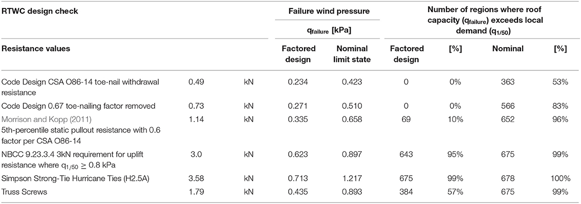
Table 4. Design check for RTWCs showing factored and unfactored design wind pressures, adjusted for suburban terrain, as well as a comparison to the design wind pressures in NBCC (Canadian Commission on Building and Fire Codes, 2015) climate zones.
For most houses in synoptic winds, Table 4 provides a realistic assessment of design. These results show that, when nominal limit states are considered, toe-nailed RTWCs likely sufficient for up to 0.658 kPa (considering 5th-percentile strength). Gavanski and Kopp's (2017) fragility analysis found that for a 5/12 slope, gable roof in suburban terrain, the 5th-percentile failure wind speed is ~43 m/s. This corresponds to a wind pressure of 0.51 kPa, which most closely compares to the code-calculated, unfactored design results in Table 4. Besides capacity values, the fragility analysis considers variations in all limit states parameters, meaning that the 5th-percentile roof capacity represents a combination of worst-case loading and capacity scenarios. This explains why Gavanski and Kopp (2017) 5th-percentile condition represents a lower wind pressure than currently calculated using Morrison and Kopp (2011) data. It is also shown that the Part 9 requirement for 3 kN uplift resistance where q1/50 ≥ 0.8 kPa meets its design target for suburban terrain when considering synoptic winds.
The implication of reduced localized wind loads resulting from rough terrain means that a house located in a suburban setting can resist a higher design-level wind event (q1/50) than a similar building exposed to open terrain. The open terrain situation, and therefore Table 3, may apply to exposed houses such as those in rural settings, on edges of neighborhoods, or exposed to flat areas such as school yards or waterfronts. It is also believed that the open exposure condition is more representative of tornado wind loads. As discussed in Gavanski and Kopp (2017) and addressed in the Tornado Commentary of ASCE 7-16 (Structural Engineering Institute, 2016), terrain does not have significant influence on the near-ground wind speeds in tornadoes. Tornadoes are localized events, where the inflow near the ground forces high tangential and radial wind speeds, in addition to vertical flows. The results of Gavanski et al. (2013) show that immediate surroundings, such as neighboring houses, cause marginal effects on the wind pressures on roofs, and that those effects change in magnitude (shielding vs. enhancing) with wind direction.
Contrary to the present, design-based results, including those calculated using the experimental results from Morrison and Kopp (2011); Morrison et al. (2012) found that their full-scale, toe-nailed gable roof is expected to be able to withstand design wind loads for almost all regions in the United States and Canada. The difference in these results may be attributed to several factors, including; neglect of internal pressures in Morrison et al. (2012) study and the effect of load sharing between RTWCs. While internal pressures have been shown to worsen the effects of external uplift, it is expected that load sharing plays a large role in increasing the capacity of roof systems.
Load sharing is expected to contribute to roof strength since the weakest connections are supported by their neighbors. This has been proven for toe-nailed RTWCs in recent studies (Khan, 2012; Morrison et al., 2012; Guha and Kopp, 2014; Navaratnam, 2016). Analogous to the load sharing behavior of entire roofs is that of individual sheathing panels. Murphy et al. (1996) compared individual fastener capacity to the average fastener strength from testing entire panels. Their results found that the mean, per-nail capacity from the panel tests is ≈15% lower than the mean of individual nail test results; however, the panel capacity results showed lower variability such that the 5th-percentile panel capacity was approximately twice that for individual nails. Load sharing between fasteners increases with increasing stiffness of the system.
Although wood-framed roofs are relatively flexible systems, full-scale experiments have shown that load sharing plays a significant role that should be allowed for in design (Gupta, 2005; Morrison et al., 2012; Henderson D. J. et al., 2013). In current Part 4 NBCC (Canadian Commission on Building and Fire Codes, 2015) provisions, load sharing is inherently assumed by load calculations for the Main Wind Force Resisting System. The unit size of building components is considered in calculating wind loads because high peak pressures occur over relatively small, localized areas on the surface of a building (Kopp and Morrison, 2018). Discrete components and cladding are designed to withstand the expected high magnitude, localized pressures that, according to area-averaging, increase for smaller effective surface areas. The overall structure is designed to withstand global, area-averaged pressures, where it is assumed that the localized peaks are dispersed and resisted by the building as a unit.
While the magnitude of wind loads is decreased based on the assumption that the whole structure participates in the building response, the capacity of the system is still assessed based on a tributary area approach, where each fastener acts alone to resist loads acting on an exclusive area of roof surface. This approach results in over-estimated reactions at each fastener; in reality, the effective areas of each fastener can overlap depending on the variability in strength between them. Since load-sharing implies that roof capacity tends toward the mean of the fastener capacities, design calculations using 5th-percentile fastener capacity are likely still conservative. As previously mentioned, the factor of safety due to load and resistance factors is already greater than 2. Additional discussion of appropriate design targets for residential structures is provided in Critical Review of Building Code Provisions.
Guha and Kopp (2014) showed that, when considering incremental failure of RTWCs and load sharing, the probability of failure of a roof system increases with storm duration. This is because the probability of large peak pressures and number of damaging peaks, as discussed by Morrison and Kopp (2011), increases with the storm duration. Guha and Kopp (2014) addressed storm durations on the order of 1–5 h; however, it has not been explored whether a similar trend exists based on the duration of impact of a slowly-translating tornado.
Henderson D. J. et al. (2013) commented that due to the brittle failure of hurricane ties relative to the plastic behavior of nail withdrawal, RTWCs including hurricane ties will have significantly less load-sharing than toe-nailed RTWCs. This means that the benefits of load-sharing may be seen more in the reactions at nailed connections; toe-nailed connections may withstand more damaging peaks and longer duration, design-level storms. While hurricane ties have significantly higher capacities, their failure occurs more rapidly when the limit state of an individual connection is reached. Design calculations using tributary area loading are likely to be more accurate for hurricane ties than for toe-nails. Load-sharing in RTWCs requires further investigation before it can be incorporated into design suggestions.
Additional DOD6 Failure Mode
In recent work by the authors (Stevenson et al., 2018, 2019), a new mode of roof damage pertaining to DOD6 was identified and assessed. In this failure mode, the framing members and connections within roof structures are observed to fail. This is different from the previously assumed modes of DOD6 where the roof structure fails at the RTWC. The estimated wind speeds indicate that failures of nailed stick-frame connections are expected to occur within the bound of DOD6 wind speeds, while failures within a truss should happen above this range. For this reason, the use of engineered trusses is recommended for new construction, although stick-framing is still permitted by the NBCC (Canadian Commission on Building and Fire Codes, 2015).
Wall Failure
Beyond DOD6, FR12 assesses other major structural failures, including wall collapse and entire removal of the structure. DOD5, shifting of the house from its foundation, should also be mentioned since it relates to failure at the base of the building, but with the rest of the structure remaining intact. It is observed to occur when the house is not properly anchored to the foundation and is considered to be an out-of-sequence failure relative to the other high-level DOD (Wind Science Engineering Centre, 2006).
DOD5 is addressed in the proposed resilience measures insofar that Clause 9.23.6.1 in NBCC (Canadian Commission on Building and Fire Codes, 2015) should be modified to remove 2(A), which allows wood floor joists to be embedded directly into the concrete foundation. As discussed in Sandink et al. (2018), provincial building code adoptions include variations on this clause. Neither are deemed sufficient because embedding wood members in concrete cannot be considered to provide notable or reliable uplift resistance, especially as the structure ages and the wood-concrete bond degrades. The remaining specifications in clause 9.23.6.1 involve fastening the floor structure to the foundation using embedded steel anchor bolts at 2.4 m spacing or less. These methods are supported in the present recommendations (Sandink et al., 2018).
Past research on other major wall failures has included experimental, finite element modeling, and reliability analyses of failure modes pertaining to DOD 7 to 10 (Doudak, 2005; Amini, 2012; Kumar et al., 2012; Martin et al., 2012; Zisis and Stathopoulos, 2012; Stedman, 2014; Navaratnam, 2016; Standohar-Alfano, 2016); however, much of this work has focused on idealized wall segments, where the wall bottom plate is anchored directly to the foundation, as illustrated in Figure 6A. The failure behavior of foundation anchor bolts and the in- and out-of-plane action of walls sheathed with structural wood panels are well-understood. However, Part 9 permits an alternative floor construction method that is widely applied in Canada, and rigid insulation is often used in place of external wood sheathing to meet updated energy requirements.
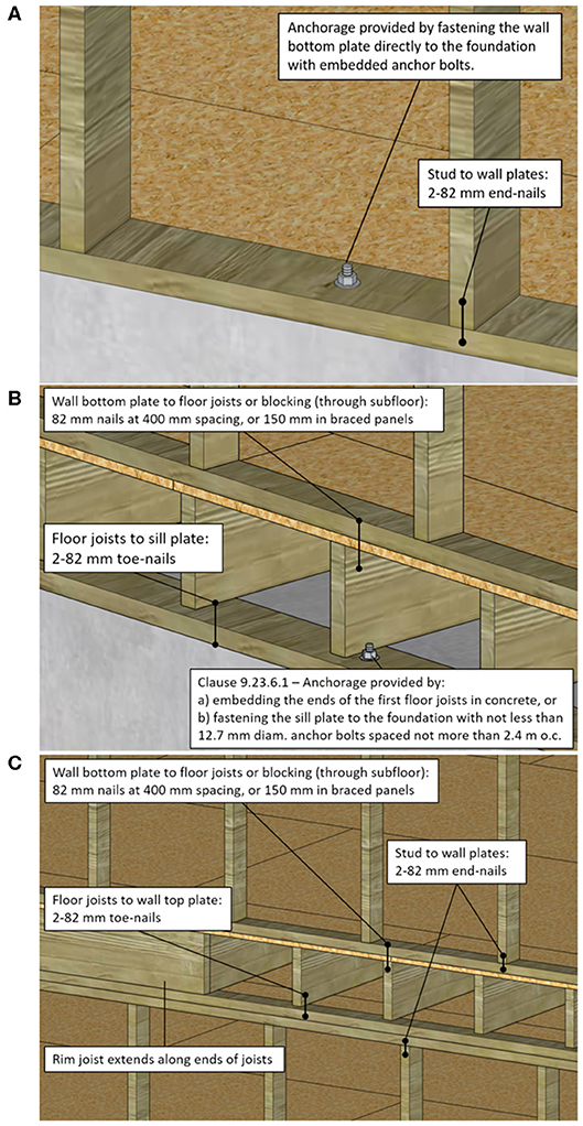
Figure 6. Wall bottom plate connection alternatives, including (A) direct wall bottom plate anchorage (as idealized in past research) and nailed connections for (B) first-story walls and (C) Inter-story floor structure. (B,C) represent common details built in accordance with NBCC (Canadian Commission on Building and Fire Codes, 2015) Part 9.
In Canada, the detail shown in Figure 6A is rarely seen. In conventional platform construction, the sill plate supporting the floor structure is the member that is anchored into the concrete foundation wall. The joists are toe-nailed to the anchored sill plate, followed by the subfloor. The load bearing walls are assembled on the ground then erected atop the subfloor and nailed in place at the base, as shown in Figure 6B. Nailing requirements in Part 9 specify 82 mm-long nails spaced at 400 mm connecting the bottom wall plate to floor joists, rims joists, or blocking, although 150 mm spacing is required in braced wall panels. It is not explicit whether nailing the bottom plate to the floor joists through the subfloor is permitted, but for the sake of constructability this is common practice. Figures 6B,C show diagrams of the common constructions for first- and second-story walls.
When the walls are not covered with structural sheathing that spans across the joints, the vertical load path relies on the nailed details shown in Figures 6B,C. As illustrated in Figure 2C and discussed in Future Work for Tornado Risk Reduction Measures, lapping exterior sheathing across the wall bottom plate and inter-story connections is a recommended method for ensuring the vertical load path (APA - The Engineered Wood Association, 2018). However, continuous exterior sheathing is not required on Part 9 structures—given that sufficient lateral bracing is provided by other means, such as interior drywall. In recent years, Canadian energy requirements have shifted practice away from using exterior sheathing due to thermal bridging behavior. For this reason, existing research on idealized, sheathed structures is not representative of the other allowed, and increasingly probable, methods of wall construction.
Figure 7 provides examples of wall failure that may be attributed to the typical Canadian details. Figure 7A shows an intact first-story subfloor, from which the wall bottom plates and structure above have been removed, and Figure 7B shows failure of the exterior walls from the second-story subfloor. Although both of the pictured failures show the final condition of these homes, and failure may have initiated in the roof or other missing components, there is a clean separation between the wall structure and the supporting floor in both cases. The lack of apparent failed wood indicates that a discontinuity existed in the connections between components.
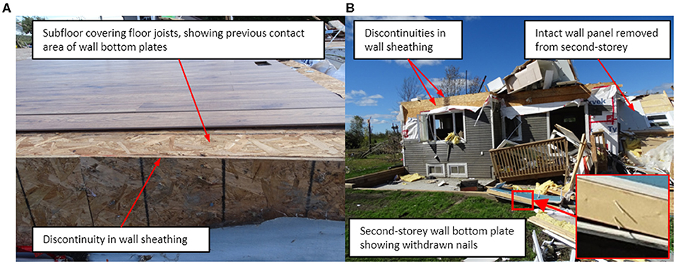
Figure 7. Examples of wall failure showing (A) remaining first-story floor structure, including interior flooring panels, with exposed subfloor around the perimeter where wall bottom plates have been removed, and (B) loss of second-story walls showing bottom plate nail withdrawal. Taken following the EF3 tornado that took place in Dunrobin, ON in September 2018.
When structural sheathing is used, the common practice is to build wall panels on the ground and sheath them before erection to ensure that they remain square during installation. After the walls are up, the floor structure is sheathed separately with thin strips of sheathing, as illustrated in Figure 2B. Beyond the fact that current codes do not require exterior wood sheathing, an additional issue exists when it is used because it does not span critical joints or contribute to the continuity of the vertical load path. The vertical load path relies on nailed connections in withdrawal or lateral directions in the majority of Canadian houses. The sufficiency of the wall bottom plate connection is discussed in context of Canadian wind design in the following section.
Figure 7A provides another interesting point for discussion. It was reported by homeowners following the Dunrobin, ON tornado in September 2018 that this home was equipped with hurricane ties at the RTWCs prior to the event. The neighboring houses suffered DOD6 roof damage; however, this one was assessed as DOD9 due to the loss of almost all walls. This was the location at which the EF3 rating for this tornado was obtained. When an event rating is obtained based on a single property and neighboring structures don't indicate a similar severity, construction quality questions commonly arise. Since this particular house reportedly had strengthened RTWCs, it is speculated that the weak link shifted from the roof to the wall-to-floor connection. It may also be the case that this failure mode occurred at comparable wind speeds to those causing DOD6 failures of nearby structures. The importance of a complete vertical load path is reiterated by this example.
It is commonly understood that wall failure occurs after loss of the roof structure once lateral restraint provided by the trusses or joists is removed. Stedman (2014) showed experimentally that buckling of exterior walls, after roof removal, can occur within DOD7 wind speeds. Their conclusions suggest that after the roof is removed, failure of walls requires even stronger gusts to collapse. Historically, wall failures such as those shown in Figure 7 and other modes pertaining to DOD7 have not been predominant in damage survey observations. Wall failures are less common than roof damage to date. However, several instances of wall bottom plate failure have been noted in recent years, especially in stronger (EF3 +) tornado events. Kopp et al. (2017) discuss another example of wall bottom plate failure that occurred in an EF2 tornado, despite the roof staying intact. This was attributed to improper construction due to no nails being visible in the failed bottom plate. Inspection of these failures suggests that a weak link may exist in the discontinuities at the bottom of the walls. The following section provides a design check of the previously unstudied mode of wall bottom plate removal due to nail withdrawal.
Engineering Design of Wall Anchorage and Inter-story Connections
Limit states design principles are applied in a similar design check to that described in Engineering Design of Roof-to-Wall Connections to evaluate the Part 9 wall details and determine the permissible design wind pressures. Wind loads, dead loads, and resistance values are calculated using Canadian standards, where the uplift limit states equation is identical for that applied to RTWCs. For lateral failure modes, the resistance factor for nails is increased to 0.8 (Canadian Standards Association, 2014), and the dead load (D) is replaced with the resisting force of static friction. Both regular wall panels and “braced” wall panels, which are required to comprise a certain proportion of exterior walls in each direction, are evaluated. The results for the archetype house in open terrain are shown in Table 5, which is divided into an uplift design check and a lateral design check. Table 6 shows the same results, adjusted to consider the wind load-diminishing effects of suburban terrain, as discussed in Engineering Design of Roof-to-Wall Connections.
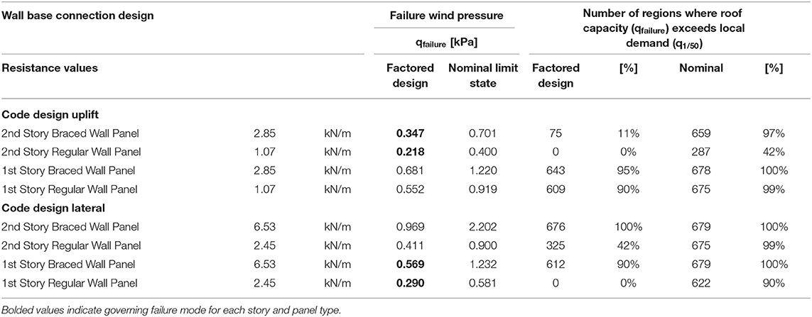
Table 5. Design check for wall anchorage showing factored and unfactored design wind pressures for uplift and lateral load effects, as well as a comparison to the design wind pressures in NBCC (Canadian Commission on Building and Fire Codes, 2015) climate zones.
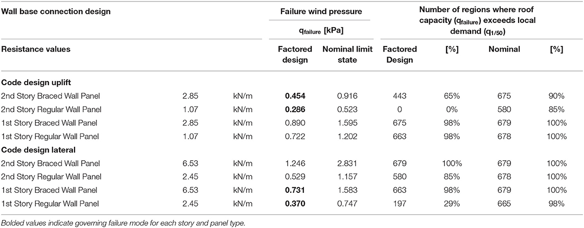
Table 6. Design check for wall anchorage showing factored and unfactored design wind pressures, adjusted for suburban terrain, for uplift and lateral load effects, as well as a comparison to the design wind pressures in NBCC (Canadian Commission on Building and Fire Codes, 2015) climate zones.
First-story and second-story walls are assessed to provide an indication of the mode of failure (uplift vs. sliding) that is likely to occur, and how dead load can influence the limit state. The second-story walls are only subjected to dead loads from their own weight plus the weight of the roof, while the base of the first-story walls support the weight of both walls, the roof, the upper floor structure, and the second-story contents, which are estimated according to live load specification in Part 4 [NBCC (Canadian Commission on Building and Fire Codes, 2015)]. The design check for wall fasteners shows that direct withdrawal of the nailed connections under uplift governs for the upper floor, while lateral withdrawal (sliding) failure governs at the ground floor. The wind pressure corresponding to the governing failure mode for each component is bolded. The Table 5 results show that, according to design, nailed wall bottom plate connections are not sufficient in all regions in which they are allowed. The nominal results suggest that the nailing pattern specified for braced wall panels may be more suitable for use around the entire perimeter of houses in regions facing normal wind risk.
The capacity of nailed wall bottom plate connections can also be compared to that of the required anchorage at the supporting sill plate. Considering the floor structure illustrated in Figure 6B, it should be expected, given that there is a requirement for building anchorage, that the elements directly adjacent to the anchors should provide similar resistance to wind uplift. While the NBCC (Canadian Commission on Building and Fire Codes, 2015) does not specify strength of required anchors, Simpson Strong-Tie Anchor Designer software indicates that the uplift resistance of typical anchor bolts is approximately 12 kN (≈ 5 kN/m). The nailed wall connections therefore have, at most, 60% of the capacity per meter that anchor bolts provide at the sill plate. The floor's uplift resistance is further assisted by a greater dead load contribution from the floor structure and first-story contents.
The nominal results for a house in suburban terrain represent the most common scenarios of wall capacity, where the redundancy of load and resistance factors are removed and wind loads represent that for a typical suburban house. Second-story walls are shown to be susceptible to uplift even when 150 mm nail spacing is used. In this case, inter-story connections should be strengthened to ensure that the entire, “sandwiched” floor structure stays intact from the lower wall studs to the upper wall studs. The second-story design checks can also be considered representative of a single-story house, where the walls are only subjected to dead loads from the roof.
Under the weight of the second-story structure and contents, the design check shows that the first-story, regular wall panels (400 mm nail spacing) are extremely susceptible to lateral failure in the archetype house. Bottom plate failure is estimated to occur at lower wind loads than failure of a roof with hurricane ties. While this result corresponds with a speculated failure sequence for the house in Figure 7A, it should be noted that the present capacity results may be over-simplified. These results suggest that wall failures would likely happen more frequently than they are currently documented in damage surveys, so sources of uncertainty should be addressed.
The present analysis does not consider the contribution of non-structural components to system stiffness, or load sharing from regular wall panels to neighboring braced wall sections. As a minimum, braced wall panels are required to make up 25% of the length of exterior walls and it is expected that load sharing influences the overall wall capacity. Past studies have modeled the wind load path to understand how roof loads are distributed to the foundation connections (Martin et al., 2012; Pfretzschner et al., 2014). This work found that roof uplift loads are not uniformly transmitted to the foundation; when houses are uniformly loaded, side walls experience higher uplift, load accumulations occur to either side of openings with some redistribution to the other walls, large openings such as garage doors can result in total loss of load carried by that wall, and loads near the ends of the building are concentrated directly below the roof peak on gable end walls. These observations suggest that, like roofs, walls also demonstrate load sharing to stiffer segments.
Navaratnam (2016) completed full-scale testing of a house constructed to Australian standards. Uplift was applied to the roof of the test structure during different construction phases so that the contribution of non-structural, finishing details could be observed. This work found that non-structural elements such as ceiling cornices accounted for a 20% reduction in the load transferred through the RTWCs, meaning that these elements may participate in vertical load transfer across nailed joints. To the authors' knowledge, no other study exists to evaluate the incidental contribution of non-structural elements (wall baseboard/trim, electrical fixtures, ductwork, etc.) to roof and wall load paths. It is expected that they play a role, but detailed models are required.
Critical Review of Building Code Provisions
When assessed from a structural design standpoint (i.e., Part 4 of NBCC), houses built to Part 9 of the NBCC provisions appear to be incapable of resisting their design-level wind loads by a large margin. However, the major structural failures discussed in Major Roof Damage and Wall Failure are not generally observed outside of extreme events, such as tornadoes. It may be argued that the target reliability for engineered structures, as governed by Part 4, are too conservative for residential design due to the neglect of the structural contributions of non-structural components and the fact that the vast majority of houses are constructed in suburban settings, where the worst-case wind loads would not apply. By definition, Part 4 requirements apply to the structural system, which comprises elements that are sized, arranged, and fastened together ensure that the design loads are resisted. On the other hand, Part 9 specifications encompass a large number of objectives in addition to life safety, including affordability and energy efficiency to name but two. In general, Part 9 requirements are empirically provided by “tried-and-tested” methods based on historical practice within the normal range of environmental demands, without target reliabilities being directly assessed.
Within such a framework, the current analysis suggests that the current prescriptive design provisions for RTWCs may be adequate for suburban regions with q1/50 up to about 0.6 kPa, rather than 0.8 kPa that is currently allowed. However, the nailed wall bottom plate connections are still deemed structurally insufficient, especially considering that foundation anchorage requirements at the final link in the vertical load path provide nearly twice the resistance of nailed wall-to-floor connections.
Recommendations for Improved Wind-Resilience for High Winds
As mentioned in Engineering Design of Roof-to-Wall Connections regarding terrain roughness, the authors believe that limit state calculations for houses in open terrain, such as those shown in Tables 3, 5, provide an appropriate representation of structural performance in tornado wind fields (Kopp, 2018). Gavanski and Kopp (2017) worked under the same assumption to refine EF-Scale wind speeds pertaining to roof failures, while Gavanski et al. (2013) showed that immediate surrounding houses do not have significant shielding or enhancing effects on roof pressures in atmospheric boundary layer winds. As such, the present calculations show that improvements to the current Part 9 design provisions are required if houses are to be constructed to withstand EF2 tornadoes, which produce wind pressures in the range of 0.7–1.0 kPa.
For regions where q1/50 > 0.8 kPa, Gavanski et al. (2013) recommend that engineering guidance be provided for the design of roof sheathing. However, their analysis identified several options that would be sufficient to resist wind pressures exceeding 0.8 kPa. Their fragility results show that roofs using 8d spiral nails at 150 mm spacing would have less than 0.1% probability of a single panel failing at 1 kPa. This nailing pattern is shown in Figure 4B. 16-gauge staples at 150 mm spacing or 8d spiral nails with 300 mm spacing on interior supports are shown to have a similarly low likelihood of panel loss at 0.8 kPa. These results assume that there are no significant openings in the building envelope, which would increase the likelihood of panel failure due to internal pressurization.
Structural weak links identified in Canadian tornado damage surveys are verified by the present calculations. Toe-nailed RTWCs are shown to provide 5th-percentile resistance of 0.50 kPa (Table 3), while wall bottom plate connections are shown to fail at 0.48 kPa in upper- or single-story walls, or at 0.74 kPa in the first-story walls of a multi-story house. The wall resistance values represent a weighted average of regular- and braced-wall panel resistance from the results in Table 5, assuming that 25% of a wall must comprise braced panels. The present calculations have been deemed conservative for aforementioned reasons, with greater uncertainty in the wall assessment. It is expected based on damage survey observations that toe-nailed RTWCs fail before walls in the majority of events; however, it can be generally concluded that many houses built to current prescriptive standards would experience serious structural damage during an EF1 tornado.
Proposed strengthening measures for RTWCs are included in the present calculations. The results indicate that hurricane ties offer the most significant improvement by providing resistance up to 0.93 kPa. Proprietary truss screws are also assessed to provide resistance up to 0.68 kPa. The input capacity for both proprietary products are taken from supplier catalogs, although it is noted that manufacturers are required to publish the lowest result of ultimate load testing (Simpson Strong-Tie, 2018). It is likely permissible to assume a higher capacity for both proprietary RTWC fasteners than is presently discussed. It is also noted that trusses are toe-nailed in place during erection, prior to installation of strengthening fasteners. The combination of toe-nails and other fasteners may provide an even higher unit capacity for RTWCs improved using either of the strengthening measures (van de Lindt et al., 2012). An additional recommendation, which is mentioned in Sandink et al. (2018) but has not yet been analyzed, is the use of continuous wood sheathing in combination with raised-heel trusses. Raised-heel trusses provide a vertical face for nailing wall sheathing to such that structural sheathing can span across the roof-to-wall interface.
Options for improving the vertical load path at wall bottom plate connections are not analyzed in the present calculations due to the complexity of the structural system effects and load sharing at the wall level as compared to the roof. However, qualitative recommendations that have been deemed appropriate by expert stakeholders (Sandink et al., 2018) are indicated in Figure 2C. The suggested improvements include use of continuous external structural sheathing that spans across all discontinuities in the wall structure or use of flat metal straps that span the critical joints. These alternatives will be included in detailed models of additional house archetypes in the ongoing work.
Future Work for Tornado Risk Reduction Measures
A report entitled, “Increasing High Wind Safety for Canadian Home: A foundational document for low-rise residential and small buildings” (Sandink et al., 2018) was recently published to propose practical solutions for improving wind-resilience of houses. In the report, rationale for improved construction is provided, improvements are recommended based on the opinions of a committee of industry stakeholders, and the expected benefits of the recommendations are assessed.
Since different regions of the country face different levels of tornado risk, as shown in Figure 1, a tiered approach was deemed appropriate for the prescriptive recommendations in Sandink et al. (2018). Measures that address a prevalent weakness have the highest priority for implementation in all regions. The modes pertaining to significant structural damage or failure of the building envelope are addressed in Tier 1 and Tier 2, as indicated in Table 7 and Figure 2C. Tier 1 measures are inexpensive changes recommended for all regions, while Tier 2 measures may be applied in regions facing elevated wind or tornado risk. Additional measures that would further improve the load path or contribute to preventing secondary issues such as internal pressurization are considered in higher tiers. These measures still require full three-dimensional analyses that consider all of the details, including the role of non-engineered elements.
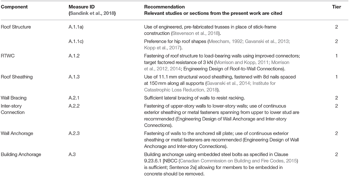
Table 7. Summary of recommendations from Sandink et al. (2018) that are relevant to the present analyses.
To determine actual built details to support detailed structural analysis, a project has been initiated in collaboration with Doug Tarry Homes Ltd., a local residential developer. The project involves 100 residential lots, which are being constructed by five different homebuilders, including by the developers' own crews. As part of the purchase agreement for the lots, all builders are required to implement three key design features; improved RTWCs through use of hurricane clips or proprietary truss screws, the use of 8d nails at 150 mm for fastening roof sheathing, and an improved detail for tying roof overhangs to the roof structure. The latter provision has not been explored in the present work. Figure 8 shows examples of inspection photos verifying the sheathing and RTWC details.
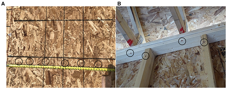
Figure 8. Example inspection photos from the Climate Resiliency Pilot Project showing (A) sheathing nail spacing, and (B) RTWCs using the proprietary screws, as well as screws fastening the wall studs to the top plate. This is an additional measure that is considered best practice for houses that do not have continuous external sheathing.
This project is of significance to the ongoing research because it provides an opportunity for builder feedback on the ease of implementation of two of the “Tier 1” recommendations. Preliminary site interviews have found that there are no major complaints regarding the use of truss screws in RTWCs or longer nails for sheathing, aside from the additional time required to install screws at every RTWC—although the screws provide a more time-efficient alternative to hurricane ties, which require up to 10 nails per connection. This feedback serves as a reminder that the most practicable and affordable solutions are required to earn industry buy-in and support for code adoption. In addition to builder feedback, regular site inspections are carried out. This allows the authors the opportunity to view and assess the multitude of details that are required in house construction, as well as variations that may not arise in design but influence house performance. Future work will provide the results of detailed structural analysis of the actual built details.
Conclusions
Over decades of work, damage surveys following tornadoes suggest trends in structural failures. Examination of the commonly observed failure modes identifies elements that may be vulnerable to design-level straight line winds as well as extreme events such as tornadoes. The present analysis assesses the design adequacy of these elements and shows how the current Part 9 provisions measure up to design targets for tornado-resilience. The present calculations and discussion provide justification for the primary recommendations presented in Sandink et al. (2018), which were previously defined based on qualitative assessments. The foremost recommendations and their suggested implementation are illustrated in Figure 2C.
The main conclusions are as follows:
- Table 9.23.3.1 in the NBCC (Canadian Commission on Building and Fire Codes, 2015) specifies three, 82 mm toe-nails at the RTWC for all regions where q1/50 ≤ 0.8 kPa. However, the present calculations indicate that such connections are only sufficient up to about 0.6 kPa for houses in suburban terrain. Beyond this threshold, improved connections such as truss screws or hurricane ties should be required. The NBCC should be revised as such.
- The current method of wall construction in Canada is to nail wall panels onto the floor structure, which is anchored at the sill plate. Nailed wall bottom plate connections are shown to be significantly weaker in shear and uplift than the adjacent requirement for anchorage. This discontinuity is believed to result in a previously unstudied failure mode where intact wall panels are removed from atop the floor membrane. The current results indicate that this failure mode could occur at as low as 0.4 kPa in a tornado, although detailed analyses are required to better understand load sharing in walls and system effects that may contribute to their strength. Since the present calculations indicate that wall failures may occur at similar wind pressures as RTWCs, the possibility of shifting the weak link in a house by improving only the RTWC should be considered.
- The open terrain roughness scenario is considered to be more representative of the tornado wind field, resulting in the assumption of reduced house capacity during tornadoes. Regarding all three notable failure modes; loss of roof sheathing, RTWCs failure, and wall base collapse, it is determined that current Part 9 provisions are insufficient to withstand EF2 tornado wind pressures.
- Based on the present calculations and qualitative assessment, recommendations are presented for improving the vertical load path and building envelope to resist EF2 tornadoes. Recommendations include longer nails at closer spacing for fastening roof sheathing, improved RTWCs such as hurricane ties or truss screws, and continuous sheathing or metal ties to span discontinuities in wall-to-floor framing.
The present work has benefitted from the significant work that has been carried out related to sheathing and RTWCs to date. Similarly detailed analyses for wall failure modes in Canadian houses has not been completed. Since current knowledge limits parts of the analysis to design calculations, the present discussion uses the most representative limit state as a basis for assessment. However, it is expected that many additional details are required to accurately assess wall load paths, capacity from non-structural elements and the effect of building contents. Work is ongoing to develop detailed models that assess the entire residential system, and field work mentioned in the previous section will ensure that as many variations are captured as possible. Future work will provide a holistic evaluation of houses that pertain to Part 9 of the NBCC and prescriptive recommendations for improved wind-resilience will be refined.
Data Availability Statement
All datasets generated for this study are included in the article/Supplementary Material.
Author Contributions
SS is a Ph.D. Candidate under the co-supervision of GK and AE. This work is a portion of SS's doctoral research. The hypothesis and approach to the work were conceived collaboratively by the authors. SS performed all analyses, interpreted the results, and drafted the manuscript for submission under the direct supervision of GK and AE. GK and AE advised calculation methods, interpretation of the results, and provided evaluation of the manuscript for publication. The authors agree to be accountable for all aspects of the work in ensuring that questions related to the accuracy or integrity of any part of the work are appropriately investigated and resolved. All authors contributed to the article and approved the submitted version.
Conflict of Interest
The authors declare that the research was conducted in the absence of any commercial or financial relationships that could be construed as a potential conflict of interest.
Acknowledgments
SS is grateful to Natural Science and Engineering Research Council of Canada (NSERC) for financial support through the Vanier Canada Graduate Scholarship. The authors gratefully acknowledge financial support from the Institute for Catastrophic Loss Reduction (ICLR) and NSERC under the Collaborative Research and Development (CRD) program, and ImpactWX who supported the damage surveys discussed herein. The authors gratefully acknowledge the ongoing support from Mr. Paul Kovacs (ICLR) and the efforts of Mr. Dan Sandink (ICLR), who led preparation of the related report in accordance with Canadian standards development process and assembled the stakeholder committee for feedback. The contribution of 19 stakeholder committee members, who participated in workshops to refine the proposed measures, offered valuable suggestions for the ongoing work. Mr. Doug Tarry is also acknowledged for providing the authors with access to a large number of residential sites for collection of data and builder feedback, and for championing the introduction of wind-resilience measures in the local homebuilding industry.
Supplementary Material
The Supplementary Material for this article can be found online at: https://www.frontiersin.org/articles/10.3389/fbuil.2020.00099/full#supplementary-material
Supplementary Data Sheet 1. Example of calculation for estimating the failure wind pressure using the limit states equation.
References
Allen, D. E. (1984). Tornado Damage at Blue Sea Lake and Nicabong, Quebec, July 1984. Ottawa, ON: National Research Council of Canada.
Allen, D. E. (1986). Tornado Damage in the Barrie/Orangeville Area, Ontario, May 1985. Ottawa, ON: National Research Council of Canada.
Amini, M. O. (2012). Determination of Rational Tornado Design Wind Speed for Residential Woodframe Structures. Tuscaloosa, AL: University of Alabama.
Amini, M. O., and van de Lindt, J. W. (2014). Quantitative insight into rational tornado design wind speeds for residential wood-frame structures using fragility approach. J. Struct. Eng. 140:04014033 doi: 10.1061/(ASCE)S.T.1943-541X.0000914
APA - The Engineered Wood Association (2018). Building for High Wind Resistance in Light-Frame Wood Construction. Form No. M310D. Tacoma, WA: APA.
Bartlett, F. M., Hong, H. P., and Zhou, W. (2003). Load factor calibration for the proposed 2005 edition of the national building code of Canada: companion-action load combinations. Can. J. Civil Eng. 30, 440–448. doi: 10.1139/l02-086
Canadian Commission on Building and Fire Codes (2015). National Building Code of Canada, 14th Edn. Ottawa, ON: National Research Council of Canada.
Canadian Commission on Building and Fire Codes (2017). Structural Commentaries; User's Guide - NBC 2015: Part 4 of Division B, 4th Edn. Ottawa, ON: National Research Council.
Canadian Standards Association (2014). CSA O86-14 Engineering Design in Wood. Mississauga, ON: CSA Group.
Carter, A. O., Millson, M. E., and Allen, D. E. (1989). Epidemiologic study of deaths and injuries due to tornadoes. Am. J. Epidemiol. 130, 1209–1218. doi: 10.1093/oxfordjournals.aje.a115449
Cheng, J. (2004). Testing and analysis of the toe-nailed connection in the residential roof-to-wall system. Forest Prod. J. 54, 58–65. Available online at: https://search.proquest.com/openview/6dd9a18e3dcf83779cb1feccbe4bdf94/1.pdf/advanced
Cheng, V. Y., Arhonditsis, G. B., Sills, D., Auld, H., Shephard, M. W., Gough, W. A., et al. (2013). Probability of tornado occurence across Canada. J. Clim. 26, 9415–9428. doi: 10.1175/JCLI-D-13-00093.1
Dao, T. N., and van de Lindt, J. W. (2008). New nonlinear roof sheathing fastener model for use in finite-element wind load applications. J. Struct. Eng. 134, 1668–1674. doi: 10.1061/(ASCE)0733-9445(2008)134:10(1668)
Datin, A. M., Prevatt, D. O., and Pang, W. (2011). Wind-uplift capacity of residential wood roof-sheathing panels retrofitted with insulating foam adhesive. J. Architect. Eng. 17, 144–154. doi: 10.1061/(ASCE)AE.1943-5568.0000034
Doudak, G. (2005). Field Determination and Modeling of Load Paths in Wood Light-Frame Structures (Ph.D. thesis). McGill University, Montreal, QC, Canada.
Ellingwood, B. R., Rosowsky, D. V., Li, Y., and Kim, J. H. (2004). Fragility assessment of light-frame wood construction subjected to wind and earthquake hazards. J. Struct. Eng. 130, 1921–1930. doi: 10.1061/(ASCE)0733-9445(2004)130:12(1921)
Environment Canada (2013). Environment and Climate Change Canada: Enhanced Fujita Scale. Available online at: https://www.canada.ca/en/environment-climate-change/services/seasonal-weather-hazards/enhanced-fujita-scale-wind-damage.html (accessed February 17, 2020).
Environment Canada (2018). Canadian National Tornado Database: Verified Events (1980-2009). Available online at: http://donnees.ec.gc.ca/data/weather/products/canadian-national-tornado-database-verified-events-1980-2009-public/ (accessed October 13, 2018).
Gavanski, E., and Kopp, G. A. (2017). Fragility assessment of roof-to-wall connection failures for wood-frame houses in high winds. J. Risk Uncertain. Eng. Syst. 30:4017013. doi: 10.1061/AJRUA6.0000916
Gavanski, E., Kopp, G. A., and Hong, H. P. (2014). Reliability analysis of roof sheathing panels on wood-frame houses under wind loads in Canadian cities. Can. J. Civil Eng. 41, 717–727. doi: 10.1139/cjce-2013-0549
Gavanski, E., Kordi, B., Kopp, G. A., and Vickery, P. J. (2013). Wind loads on roof sheathing of houses. J. Wind Eng. Ind. Aerodyn. 114, 106–121. doi: 10.1016/j.jweia.2012.12.011
Ginger, J., Henderson, D., Leitch, C., and Boughton, G. (2007). Tropical cyclone larry: estimation of wind field and assessment of building damage. Austr. J. Struct. Eng. 7, 209–224. doi: 10.1080/13287982.2007.11464977
Graettinger, A. J., Ramseyer, C., Freyne, S., Prevatt, D. O., Myers, L., Dao, T. N., et al. (2014). Tornado Damage Assessment in the aftermath of the May 20th 2013 Moore Oklahoma Tornado. Tuscaloosa, AL: The University of Alabama.
Guha, T. K., and Kopp, G. A. (2014). Storm duration effects on roof-to-wall-connection failures of a residential, wood-frame, gable roof. J. Wind Eng. Ind. Aerodyn. 133, 101–109. doi: 10.1016/j.jweia.2014.08.005
Gupta, R. (2005). System behaviour of wood truss assemblies. Progr. Struct. Eng. Mater. 7, 183–193. doi: 10.1002/pse.203
He, W. X., and Hong, H. P. (2012). Probabilistic characterization of roof panel uplift capacity under wind loading. Can. J. Civil Eng. 39, 1285–1296. doi: 10.1139/l2012-114
Henderson, D., Williams, C., Gavanski, E., and Kopp, G. A. (2013). Failure mechanisms of roof sheathing under fluctuating wind loads. J. Wind Eng. Ind. Aerodyn. 114, 27–37. doi: 10.1016/j.jweia.2013.01.002
Henderson, D. J., Morrison, M. J., and Kopp, G. A. (2013). Response of toe-nailed, roof-to-wall connections to extreme wind loads in a full-scale, timber-framed, hip roof. Eng. Struct. 56, 1474–1483. doi: 10.1016/j.engstruct.2013.07.001
Institute for Catastrophic Loss Reduction (2018). Durham Region Climate Resilience Standard for New Houses. Toronto, ON: ICLR.
Insurance Institute for Business Home Safety (2015a). Fortified Home - Existing Homes; High Wind Technical Summary. Available online at: http://fortifiedhome.org/wp-content/uploads/2019/06/FORTIFIED-Home-High-Wind-Existing-Technical-Summary.pdf (accessed January 10, 2020).
Insurance Institute for Business Home Safety (2015b). Fortified Home - New Construction; High Wind Technical Summary. Available online at: http://fortifiedhome.org/wp-content/uploads/2019/06/FORTIFIED-Home-High-Wind-New-Technical-Summary.pdf (accessed January 10, 2020).
Insurance Institute for Business Home Safety (2020). Fortified Home. Available online at: https://fortifiedhome.org/ (accessed January 10, 2020).
Khan, M. A. (2012). Load-Sharing of Toe-Nailed, Roof-to-Wall Connections Under Extreme Wind Loads in Wood-Frame Houses (M.Sc. thesis). Western University, London, ON, Canada.
Kopp, G., and Wu, C.-H. (2017). “A framework for the aerodynamics of low-rise buildings in tornadoes: can boundary layer wind tunnels give us everything we need?,” in Proceedings of the 13th Americas Conference on Wind Engineering (Gainesville, FL, 21–24.
Kopp, G. A. (2018). A Wind Engineer's Perspective on Wind Speed Estimation in Tornadoes. Champaign, IL: Keynote Presentation to the Tornado Hazard Wind Assessment and Reduction Symposium.
Kopp, G. A., Hong, E., Gavanski, E., Stedman, D., and Sills, D. (2017). Assessment of wind speeds based on damage observations from the Angus (Ontario) Tornado of 17 June (2014). Can. J. Civil Eng. 44, 37–47. doi: 10.1139/cjce-2016-0232
Kopp, G. A., and Morrison, M. J. (2018). Component and cladding wind loads for low-slope roofs on low-rise buildings. J. Struct. Eng. 144:04018019. doi: 10.1061/(ASCE)ST.1943-541X.0001989
Kopp, G. A., Oh, J. H., and Inculet, D. R. (2008). Wind-induced internal pressures in houses. J. Struct. Eng. 134, 1129–1138. doi: 10.1061/(ASCE)0733-9445(2008)134:7(1129)
Kumar, N., Dayal, V., and Sarkar, P. P. (2012). Failure of wood-framed low-rise buildings under tornado wind loads. Eng. Struct. 39, 79–88. doi: 10.1016/j.engstruct.2012.02.011
Lee, K. H., and Rosowsky, D. V. (2005). Fragility assesment for roof sheathing failure in high wind regions. Eng. Struct. 27, 857–868. doi: 10.1016/j.engstruct.2004.12.017
Malik, F., Brown, R., and York, W. (2012). “IBHS FORTIFIED Homes Hurricane; Bronze, silver and gold: an incremental, holistic approach to reducing residential property losses in hurricane prone areas,” in ATC and SEI Conference on Advances in Hurricane Engineering (Miami, FL), 212–228. doi: 10.1061/9780784412626.020
Martin, G. K., Gupta, R., Prevatt, D. O., Datin, P. L., and van de Lindt, J. W. (2012). Modeling system effects and structural load paths in a wood-frame structure. J. Architect. Eng. 17, 134–143. doi: 10.1061/(ASCE)AE.1943-5568.0000045
Masters, F. J., Gurley, K. R., Shah, N., and Fernandez, G. (2010). The vulnerability of residential window glass to lightweight windbourne debris. Eng. Struct. 32, 911–921. doi: 10.1016/j.engstruct.2009.12.016
Meecham, D. (1992). The improved performance of hip roofs in extreme winds - a case study. J. Eng. Ind. Aerodyn. 43, 1717–1726. doi: 10.1016/0167-6105(92)90583-V
Ministry of Municipal Affairs and Housing (2010). Proposed Changes to the 2006 Ontario Building Code (B-09-23-06). Toronto, ON: Ministry of Municipal Affairs and Housing.
Morrison, M. J., Henderson, D. J., and Kopp, G. A. (2012). The response of a wood-frame, gable roof to fluctuating wind loads. Eng. Struct. 41, 498–509. doi: 10.1016/j.engstruct.2012.04.002
Morrison, M. J., and Kopp, G. A. (2011). Performance of toe-nail connections under realistic wind loading. Eng. Struct. 33, 69–76. doi: 10.1016/j.engstruct.2010.09.019
Morrison, M. J., Kopp, G. A., Gavanski, E., Miller, C., and Ashton, A. (2014). Asessment of damage to residential construction from the tornadoes in Vaughan, Ontario, on August 2009. Can. J. Civil Eng. 41, 550–558. doi: 10.1139/cjce-2013-0570
Murphy, S., Schiff, S. D., Rosowsky, D. V., and Pye, S. (1996). System Effects and Uplift Capacity of Roof Sheathing Fasteners. Reston VA: ASCE, 765–770.
Navaratnam, S. (2016). Wind load sharing and vertical load transfer from roof to wall in a timber-framed house (Ph.D. thesis). James Cook University, Townsville, QLD, Canada.
Northern Tornadoes Project (2020). Open Data for the Northern Tornadoes Project. Available online at: https://ntpopendata-westernu.opendata.arcgis.com (accessed January 20, 2020).
Oh, J. H., Kopp, G. A., and Inculet, D. R. (2007). The UWO contribution to the NIST aerodynamic database for wind loads on low buildings. 3: Internal pressures. J. Wind Eng. Ind. Aerodyn. 95, 755–779. doi: 10.1016/j.jweia.2007.01.007
Pfretzschner, K. S., Gupta, R., and Miller, T. H. (2014). Practical modeling for wind load paths in a realistic light-frame wood house. J. Perform. Constr. Fac. 28, 430–439. doi: 10.1061/(ASCE)CF.1943-5509.0000448
Prevatt, D. O., Coulbourne, W. L., Greattinger, A. J., Pei, S., Gupta, R., and Grau, D. (2013). Joplin, Missouri, Tornado of May 22, 2011: Structural Damage Survery and Case for Tornado-Resilient Building Codes. Reston, VA: American Society of Civil Engineers. doi: 10.1061/9780784412503
Prevatt, D. O., van de Lindt, J. W., Graettinger, A., Coulbourne, W., Gupta, R., Pei, S., et al. (2011). Damage Study and Future Direction for Structural Design Following the Tuscaloosa Tornado of 2011. Gainesville, FL: University of Florida.
Ramseyer, C., Holliday, L., and Floyd, R. (2016). Enhanced residential building code for tornado safety. J. Perform. Constr. Fac. 30:04015084. doi: 10.1061/(ASCE)CF.1943-5509.0000832
Reed, T. D., Rosowsky, D. V., and Schiff, S. D. (1997). Uplift capacity of light-frame rafter to top plate connections. J. Architect. Eng. 3, 156–163. doi: 10.1061/(ASCE)1076-0431(1997)3:4(156)
Riley, M. A., and Sadek, F. (2003). Experimental Testing of Roof to Wall Connections in Wood Frame Houses. Gaithersburg, MD: National Institute of Standards and Technology. doi: 10.6028/NIST.IR.6938
Rocha, D., Eamon, C. D., and Murphy, J. F. (2011). Reliability analysis of roof sheathing panels exposed to a hurricane wind. Struct. Saf. 33, 74–81. doi: 10.1016/j.strusafe.2010.08.003
Roueche, D. B., Lombardo, F. T., and Prevatt, D. O. (2017). Empirical approach to evaluating the tornado fragility of residential structures. J. Struct. Eng. 143:04017123. doi: 10.1061/(ASCE)ST.1943-541X.0001854
Sandink, D., Kopp, G. A., Stevenson, S. A., and Dale, N. (2018). Increasing High Wind Safety for Canadian Homes: A Foundational Document for Low-Rise Residential and Small Buildings. Toronto, ON: Institute for Catastrophic Loss Reduction.
Sills, D., Cheng, V., McCarthy, P., Rousseau, B., Waller, J., Elliot, L., et al. (2012). “Using tornado, lightning and population data to identify torndao prone areas in Canada,” in Proceedings of the American Meteorological Society 26th Conference on Severe Local Storms. Retrieved from: https://ams.confex.com/ams/26SLS/webprogram/Paper211359.html
Simmons, K. (2019). The Washington Post, Senate 'Shelter Act' is a Welcome Step Toward Fortifying U.S. Homes to Withstand Extreme Weather. Available online at: https://www.washingtonpost.com/weather/2019/07/26/senate-shelter-act-is-welcome-step-toward-fortifying-us-homes-withstand-extreme-weather/?noredirect=on (accessed January 10, 2020).
Simmons, K. M., Kovacs, P., and Kopp, G. A. (2015). Tornado damage mitigation: benefit-cost analysis of enhanced building codes in Oklahoma. Weather Clim. Soc. 7, 169–178. doi: 10.1175/WCAS-D-14-00032.1
Simpson Strong-Tie (2018). Wood Construction Connectors; Canadian Limit States Design [C-C-CAN2018].
Sparks, P. R., Schiff, S. D., and Reinhold, T. A. (1994). Wind damage to envelopes of houses and consequent insurance losses. J. Wind Eng. Ind. Aerodyn. 5, 145–155. doi: 10.1016/0167-6105(94)90023-X
Standohar-Alfano, C. D. (2016). Damage Analysis and Mitigation for Wood-Frame Structures Subjected to Tornado Loading. Fort Collins, CO: Colorado State University.
Standohar-Alfano, C. D., Estes, H., Johnston, T., Morrison, M. J., and Brown-Giammanco, T. M. (2017). Reducing losses from wind-related natural perils: research at the IBHS research center. Front. Built Environ. 3:9. doi: 10.3389/fbuil.2017.00009
Stathopoulos, T., Zisis, I., and Wang, K. (2009). Terrain Classification and Exposure Factor in the 2005 National Building Code of Canada. Taipei: TW.
Statistics Canada (2018). Census Profile, 2016 Census. Available online at: https://www12.statcan.gc.ca/census-recensement/2016/dp-pd/prof/index.cfm?Lang=E (accessed January 20, 2020).
Stedman, D. A. (2014). Full-Scale Tests of a Wood-Frame Structure under Extreme Wind Loads. London, ON: Western University.
Stevenson, S. A., El Ansary, A. M., and Kopp, G. A. (2019). A practical modelling technique to assess the performance of wood-frame roofs under extreme wind loads. Eng. Struct. 191, 640–648. doi: 10.1016/j.engstruct.2019.04.058
Stevenson, S. A., Kopp, G. A., and El Ansary, A. M. (2018). Framing failures in wood-frame hip roofs under extreme wind loads. Front. Built. Environ. 4:6. doi: 10.3389/fbuil.2018.00006
St. Pierre, L. M., Kopp, G. A., Surry, D., and Ho, T. C. (2005). The UWO contribution to the NIST aerodynamic database for wind loads on low buildings: Part 2. Comparison of data with wind load provisions. J. Wind Eng. Ind. Aerodyn. 93, 31–59. doi: 10.1016/j.jweia.2004.07.007
Structural Engineering Institute (2016). ASCE 7-16 Minimum Design Loads for Buildings and Other Structures. Reston, VA: American Society of Civil Engineers.
US Senate - Finance Committee (2019). S.1958 - 116th Congress (2019-2020). Available online at: https://www.congress.gov/bill/116th-congress/senate-bill/1958/text?r=3ands=1 (accessed January 10, 2020).
van de Lindt, J., Amini, M. O., Standohar-Alfano, C., and Dao, T. (2012). Systematic study of the failure of a light-frame wood roof in a tornado. Buildings 2, 519–533. doi: 10.3390/buildings2040519
van de Lindt, J. W., and Dao, T. N. (2009). Performance-based wind engineering for wood-frame buildings. J. Struct. Eng. 135, 169–177. doi: 10.1061/(ASCE)0733-9445(2009)135:2(169)
van de Lindt, J. W., Graettinger, A. J., Gupta, R., Skaggs, T., and Pryor, S. (2007). Performance of wood-frame structures during hurricane katrina. J. Perform. Construct. Fac. 21, 108–116. doi: 10.1061/(ASCE)0887-3828(2007)21:2(108)
Wind Science and Engineering Centre (2006). A Recommendation for an Enhanced Fujita Scale. Lubbock, TX: Texas Tech University.
Keywords: wood-frame houses, prescriptive design standards, National Building Code of Canada, wind loads, EF-Scale, tornadoes
Citation: Stevenson SA, Kopp GA and El Ansary AM (2020) Prescriptive Design Standards for Resilience of Canadian Housing in High Winds. Front. Built Environ. 6:99. doi: 10.3389/fbuil.2020.00099
Received: 17 February 2020; Accepted: 29 May 2020;
Published: 03 July 2020.
Edited by:
Weichiang Pang, Clemson University, United StatesReviewed by:
Mohammadtaghi Moravej, Independent Researcher, Los Angeles, United StatesDavid Brett Roueche, Auburn University, United States
Copyright © 2020 Stevenson, Kopp and El Ansary. This is an open-access article distributed under the terms of the Creative Commons Attribution License (CC BY). The use, distribution or reproduction in other forums is permitted, provided the original author(s) and the copyright owner(s) are credited and that the original publication in this journal is cited, in accordance with accepted academic practice. No use, distribution or reproduction is permitted which does not comply with these terms.
*Correspondence: Gregory A. Kopp, Z2Frb3BwQHV3by5jYQ==