 Liang Cao1*
 Thomas Marullo1
 Safwan Al-Subaihawi2
 Chinmoy Kolay3
 Alia Amer2
 James Ricles1,2
 Richard Sause1,2
 Chad S. Kusko1
- 1ATLSS Engineering Research Center, Lehigh University, Bethlehem, PA, United States
- 2Department of Civil and Environmental Engineering, Lehigh University, Bethlehem, PA, United States
- 3Department of Civil Engineering, Indian Institute of Technology Kanpur, Kanpur, India
The NHERI Lehigh Experimental Facility, as part of the NSF-funded Natural Hazards Engineering Research Infrastructure (NHERI) program, was established in 2016 as an open-access facility. This facility enables researchers to conduct state-of-art research on natural hazard mitigation in civil infrastructure systems, including high-performance numerical and physical testing to improve the resilience and sustainability of the civil infrastructure against natural hazards. The facility has the unique ability to conduct real-time multi-directional hybrid simulation (RTHS) on large-scale structural systems using 3D non-linear numerical models combined with large-scale physical models of structural and non-structural components. The Lehigh Experimental Facility possesses testbeds that include a lateral load-resisting system characterization testbed, a non-structural component multi-directional dynamic loading simulator, full-scale and reduced-scale damper testbeds, a tsunami and storm surge debris impact force testbed, and a soil-foundation structure interaction testbed. This paper describes the infrastructure and capabilities of the NHERI Lehigh Experimental Facility. Developments by the facility in advancing large-scale RTHS are detailed. Examples of research projects performed by users of the facility are then provided, including large-scale RTHS of steel frame buildings with magneto-rheological (MR) dampers and non-linear viscous dampers subject to strong earthquake ground motions; 3D multi-hazard large-scale RTHS of tall steel buildings subject to multi-directional wind and earthquake ground motions; characterization of a novel semi-active friction device based on band brake technology; and testing of cross-laminated timber self-centering coupled wall-floor diaphragm-gravity systems involving multi-directional loading.
1. Introduction
The Natural Hazards Engineering Research Infrastructure (NHERI) is a National Science Foundation (NSF)-supported distributed, multi-user, open-access national research infrastructure. It consists of twelve components, including the Network Coordination Office (NCO), the Computational Modeling and Simulation Center (SimCenter), the DesignSafe-Cyberinfrastructure (DesignSafe-CI), the Natural Hazards Reconnaissance (RAPID) Facility, CONVERGE, and seven Experimental Facilities (EF). The NHERI Experimental Facilities provide research tools that allow researchers to test natural hazard mitigation concepts and is located at various universities around the United States, including (1) Lehigh University, (2) the University of Texas at Austin (UTexas), (3) the University of California, Davis (UC Davis), (4) the University of Florida (UF), (5) Florida International University (FIU), (6) the University of California, San Diego (UCSD), and (7) Oregon State University (OSU). Researchers can utilize multiple facilities for a single research project. For example, wind pressures imposed on a structural system by a wind storm can be measured at a wind tunnel facility (i.e., FIU or UF) and subsequently used to define the wind loading for a real-time hybrid simulation performed at the Lehigh EF.
The NHERI Lehigh EF is an open-access facility that provides experimental resources for state-of-art research on natural hazard mitigation in civil infrastructure systems. The NHERI Lehigh EF provides a unique portfolio of experimental equipment, instrumentation, testbeds, and simulation protocols for large-scale multi-directional testing. The facility's experimental resources include a strong floor, multi-directional reaction wall, static and dynamic actuators, and test algorithms to enable researchers to conduct large-scale multi-directional dynamic testing and real-time hybrid simulation. Various testbeds are available at the NHERI Lehigh EF, including: (1) a lateral load resisting system characterization testbed; (2) full-scale damper testbeds; (3) a tsunami debris impact force testbed; (4) Lehigh Real-Time Cyber-Physical Structural Systems Laboratory; (5) a non-structural component multi-directional dynamic loading simulator; and (6) a soil-foundation structure interaction testbed. The types of testing and simulations that the NHERI Lehigh EF can perform include: (1) large-scale hybrid simulation (HS), which combines large-scale physical models with computer-based numerical simulations (Lin et al., 2013); (2) large-scale real-time hybrid simulation (RTHS), which is a HS conducted at the actual time scale of the physical models and excitations (Chen et al., 2009; Karavasilis et al., 2011; Chae et al., 2014; Dong et al., 2015); (3) large-scale real-time hybrid simulation with multiple experimental substructures, where several experimental specimens are used in an RTHS (Chen and Ricles, 2012; Al-Subaihawi et al., 2020); (4) geographically distributed hybrid simulation (DHS), which is an HS with physical models and/or numerical simulation models located in different laboratories and connected through the internet (Ricles et al., 2007); (5) geographically distributed real-time hybrid earthquake simulation (DRTHS), which combines DHS and RTHS (Kim et al., 2012); (6) dynamic testing (DT), which use high speed servo-controlled hydraulic actuators at real-time scales to impose predefined force or displacement histories (Ricles et al., 2002a; Chae et al., 2013b; Riggs et al., 2014); and (7) quasi-static testing (QS) of physical models using predefined force or displacement histories (Ricles et al., 2002b; Zhang and Ricles, 2006; Perez et al., 2013). A broad array of instrumentation, large-scale data acquisition systems, and advanced sensors is available to acquire the system-level data needed to support the goal of advancing computational modeling and simulation. All test results and research data are shared through the NHERI DesignSafe-Cyberinfrastructure using the Data Depot, a multi-purpose data repository for experimental, simulation, and field data (https://www.designsafe-ci.org/data/browser/public/).
The unique ability of the NHERI Lehigh EF is the real-time hybrid simulation (RTHS) methodology. RTHS is a cost-effective and efficient experimental tool that divides a structural system into experimental and analytical substructures where, in the former, components of the system not well-understood and for which accurate computational models do not exist are modeled physically in the laboratory. The latter (i.e., the analytical substructure) includes components with well-understood dynamic behavior that are modeled numerically in the computer. The natural hazard mitigation performance of load-rate-dependent devices, such as rotary friction dampers (Cao et al., 2015) and viscoelastic dampers (Lee et al., 2005) can be experimentally investigated using RTHS methodology. The RTHS performed at the NHERI Lehigh EF uses the unconditionally stable parametrically dissipative MKR-α integration algorithm developed by the authors (Kolay and Ricles, 2019). For the analytical substructures, the numerical modelings and state-determination process use explicit-formulated elements and material state determination functions that are embedded in finite element programs developed by the authors (Kolay et al., 2018; Ricles et al., 2020b) on a real-time workstation. For the experimental substructure, an adaptive servo-hydraulic control law developed by the authors (Chae et al., 2013a), called the adaptive time series (ATS) compensator, is used to provide accurate servo-hydraulic actuator tracking capability. The algorithm and adaptive control scheme have been successfully implemented and used at Lehigh to conduct over 2000 RTHS on structures with elastomeric, viscous, and semi-active controlled dampers subjected to seismic (Chen et al., 2009; Karavasilis et al., 2012; Dong et al., 2016, 2018a,b) and wind loadings (Al-Subaihawi et al., 2020; Kolay et al., in press).
The NHERI Lehigh EF has a staff dedicated to supporting the operations of the facility (Figure 1). The facility is directed by Dr. James Ricles, who provides overall leadership and accountability for completing the mission of the facility. Dr. Richard Sause, Associate Director, provides facility technical support leadership and assistance to the Director. Thomas Marullo, Research Scientist, oversees the facility's IT systems in addition to the development and implementation of software and algorithms to support experimental protocols. Dr. Liang Cao, Research Scientist, oversees the experimental protocol configurations, user training, and site enhancements. Dr. Chad Kusko manages the facility's operations and oversees the education community outreach program. Darrick Fritchman manages the laboratory technicians who provide laboratory staff support to research projects. Dr. Shamim Pakzad provides technical capacity building support in the areas of advanced sensors and structural health monitoring. Dr. Muhannad Suleiman provides technical capacity building support in soil-structure interaction and geotechnical engineering.
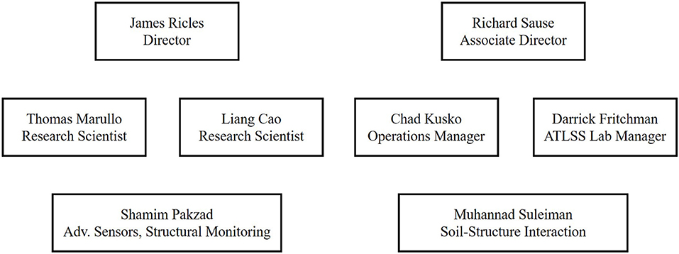
Figure 1. NHERI Lehigh experimental facility staff.
The large laboratory space, staff of skilled laboratory technicians, and multitude of equipment at the NHERI Lehigh EF enable multiple large-scale simulations and tests to be conducted simultaneously. Several experimental tests have been performed recently using the equipment and algorithms at the NHERI Lehigh EF, including (1) large-scale RTHS of a three-story steel frame building equipped with magneto-rheological (MR) dampers subject to strong earthquake ground motions; (2) large-scale RTHS of a reduced-strength steel building with non-linear viscous dampers subject to strong earthquake ground motions; (3) 3D multi-hazard large-scale RTHS of a tall steel frame building with non-linear viscous dampers subject to multi-directional wind and earthquake ground motions; (4) characterization of a novel semi-active friction device based on band brake technology; and (5) performance testing of cross-laminated timber self-centering coupled wall-floor diaphragm-gravity systems subjected to multi-directional seismic loading.
This paper is organized into five remaining sections. Section 2 presents an overview of the NHERI Lehigh EF, including the infrastructure, equipment, and various testbeds. Section 3 introduces the real-time integrated control system. Section 4 presents experimental protocols. Section 5 provides examples of research projects conducted at the NHERI Lehigh EF. Section 6 summarizes and concludes the paper.
2. Overview of the NHERI Lehigh EF
2.1. NHERI Lehigh EF Infrastructure and Equipment
The NHERI Lehigh EF is housed in the multi-directional experimental laboratory at the Advanced Technology for Large Structural Systems (ATLSS) Engineering Research Center, Lehigh University. The ATLSS Laboratory has a strong floor that measures 31.1 × 15.2 m in plan and a 30.4 m long multi-directional reaction wall that measures up to 15.2 m in height. Anchor points are spaced on a 1.5 m grid along the strong floor and walls. Each anchor point can resist 1.33 MN of tension force and 2.22 MN of shear force. Additional steel reaction frames can be used in combination with the strong floor and reaction walls to create a wide variety of test configurations. A 178-kN capacity overhead crane services the test area and an adjacent fabrication area. Additional smaller cranes with capacities of 45 and 27 kN also serve this area. The ATLSS Laboratory includes a machine shop and material testing facilities.
The NHERI Lehigh EF equipment portfolio includes the following:
1. Five large-capacity hydraulic actuators manufactured by Servotest Systems and five smaller-capacity MTS hydraulic actuators. Details will be presented in the next subsection.
2. Two high-force, heavy-duty RSA electric rod actuators manufactured by Tolomatic with an 89-mm stroke and 22.2-kN force capacity.
3. Ten three-stage 2,080 lpm high-flow-rate servo-valves. Ten service manifolds with low-pressure and high-pressure settings that operate at 24.1 MPa.
4. Five 454-lpm hydraulic pumps with an oil reservoir and two banks of accumulators that enable strong seismic ground motion effects to be sustained for up to 30 s. The accumulators supply a total accumulated oil volume of 3,030 L connected to the hydraulic pressure line. Dedicated connections exist for accessing the high-flow hydraulic supply and return lines to the pumps.
5. Two Servotest Pulsar distributed high-performance, real-time digital servo-control systems with fiber-optic-based actuator and analog node modules for use in servo-drive PID control command generation and feedback signal conditioning.
6. A high-speed 384-channel data acquisition system manufactured by Pacific Instruments, capable of acquiring data up to 4,096 Hz (4,096 samples per second) per channel.
7. A Synology network attached storage system with dual-redundancy data protection and daily mirroring to Designsafe-CI.
8. Conventional sensors, including 12 temposonic displacement sensors with 1,500 and 2,240 mm stroke, 5 triaxial and 5 uniaxial ± 10 g accelerometers, 8 bi-axis dynamic 360° inclinometers, and other sensors including LVDTs, string potentiometers, linear potentiometers, etc.
9. Two Blue Iris web camera systems capable of streaming and recording 4K HD video and time-lapse images from IP web cameras, including 22 Amcrest 8MP 4K/30 FPS IP PoE cameras and 4 Sony SNC-EP550 720p/30 FPS PTZ IP PoE cameras.
10. Auxiliary equipment including forklifts and man lifts.
In addition to the above equipment, there are 27 additional servo-hydraulic actuators that can be used for static load applications (e.g., to apply gravitational load to test specimens). These actuators range in capacity from 130 to 2,680 kN, with strokes from 250 to 1,500 mm.
Advanced sensors are also available, including two digital image correlation (DIC) systems that can perform non-contact 3-D full-field strain measurements under dynamic loading. The measurement area range is from 23 × 18 to 5000 × 3800 mm with a strain measurement resolution range of 0.05–100%. The maximum sampling rate is 500 frames/s.
2.2. NHERI Lehigh EF Testbeds
Various testbeds are available for NHERI Lehigh EF, and photographs of these testbeds are shown in Figure 2.
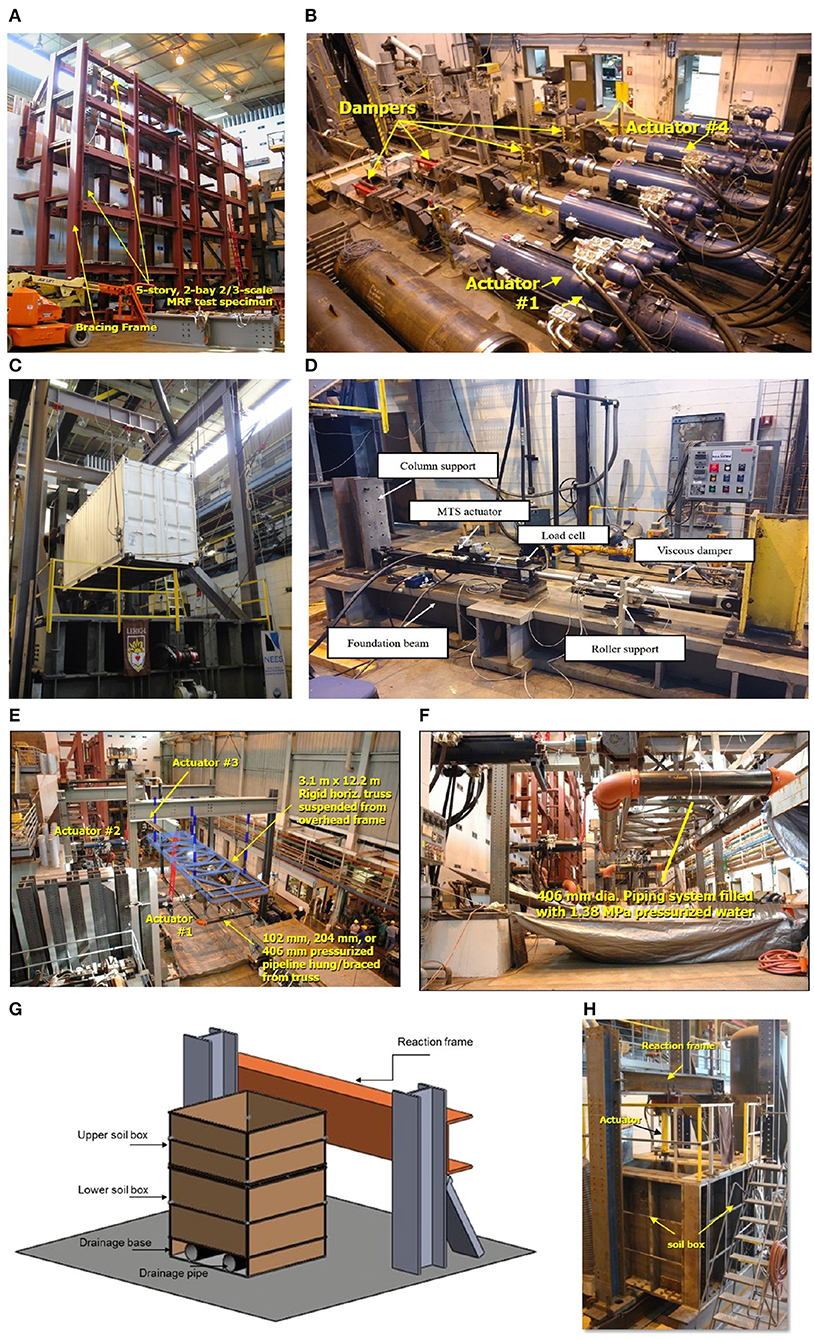
Figure 2. NHERI Lehigh EF testbeds: (A) lateral force-resisting system characterization testbed; (B) full-scale damper testbed; (C) tsunami debris impact force testbed; (D) Lehigh Real-Time Cyber-Physical Structural Systems Laboratory testbed; (E) non-structural component multi-directional dynamic loading testbed being used for real-time multi-directional hybrid simulation of a building piping system; (F) piping system details; and soil-foundation structure interaction testbed; (G) schematic; and (H) photograph.
2.2.1. Lateral Load-Resisting System Testbed
Tests, including RTHS of large-scale structural systems, can be performed using the lateral load-resisting system characterization testbed, as shown in Figure 2A. The testbed consists of a bracing frame for testing lateral load systems and has a width of 11 m and a height of 13.7 m. Figure 2A shows a photograph of a two-thirds-scale 5-story moment-resisting frame test specimen placed in the lateral load-resisting system characterization testbed.
2.2.2. Full-Scale Damper Testbed
The full-scale damper testbed in the NHERI Lehigh EF provides the ability to perform damper characterization tests and real-time hybrid simulations using full-scale dampers. Five servo-hydraulic actuators, two with a 2,300-kN capacity and three with a 1,700-kN capacity, are available. The actuator specifications are listed in Table 1. An example of a real-time hybrid simulation of a building equipped with four full-scale dampers is shown in Figure 2B, where the experimental substructure is comprised of these four dampers.
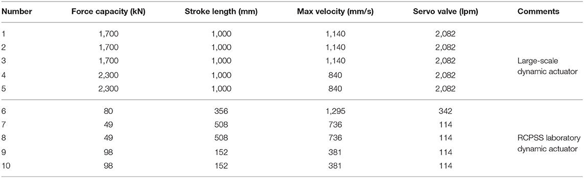
Table 1. Dynamic actuator specifications.
2.2.3. Tsunami Debris Impact Force Testbed
The tsunami debris impact force testbed is used to study water-borne debris impact forces on structures (Riggs et al., 2014). The testbed is shown in Figure 2C, where impact forces from a cargo shipping container are being investigated. Full-scale in-air impact tests were also conducted. The utility pole and shipping container were used as the debris object, suspended in a pendulum system and swung in free-fall to generate impact forces against a fixed load cell. A winch system is used to pull back the debris to the desired height. Data from all instrumentation are recorded during debris impact tests using a high-speed camera at 5,000 frames/s.
2.2.4. Lehigh Real-Time Cyber-Physical Structural Systems Laboratory
The Lehigh Real-Time Cyber-Physical Structural Systems (RCPSS) Laboratory is a multidisciplinary research facility that is focusing on small-scale dynamic testing for mitigating the effects of natural hazards on civil infrastructures. Five servo-hydraulic actuators designed and manufactured by MTS Systems Corporation are available for small-scale multi-directional dynamic tests and real-time hybrid simulations. The specifications for the actuators are listed in Table 1.
The characterization test setup of a 29-kN capacity non-linear viscous damper is shown in Figure 2D. The MTS actuator is installed on a foundation beam, and a reaction support (identified as column support in Figure 2D) and the damper are shown placed. Characterization tests are conducted using pre-defined displacement inputs.
2.2.5. Non-structural Component Multi-Directional Dynamic Loading Testbed
Large-scale dynamic tests of non-structural components can be performed using the non-structural component multi-directional dynamic loading testbed. Figures 2E,F show the experimental substructure for a real-time multi-directional seismic hybrid simulation of a building piping system using this testbed (Chen et al., 2008). The testbed consists of a 3-m wide by 12-m long rigid horizontal truss suspended from an overhead frame via four hanger rods. The non-structural components (e.g., the piping system) are attached to the horizontal truss and the laboratory's strong floor. The horizontal truss serves as a rigid floor diaphragm, and controlled bi-directional displacements are imposed on the truss using three hydraulic actuators to investigate the multi-directional dynamic performance of the non-structural components.
2.2.6. Soil-Foundation Structure Interaction Testbed
The soil-foundation structure interaction testbed consists of a vertical reaction frame and two stacked soil boxes and is shown in Figures 2G,H. The two soil boxes, each with dimensions of 1.5 × 1.5 × 1.5 m and 1.5 × 1.5 × 0.75 m were designed to allow for flexible assembly. The advanced sensors in the testbed include tactile pressure sheet sensors, in-soil null pressure sensors, customized flexible shape acceleration arrays (SAAs), and deformation sensors. The testbed also has a soil storage and moving system, vibrating table to characterize granular material compaction properties, nuclear density gauge, and web-broadcasting capability (Suleiman et al., 2014).
3. NHERI Lehigh Integrated Control System
3.1. Real-Time Integrated Control System Components
A schematic of the real-time testing architecture for the NHERI Lehigh EF is shown in Figure 3 and includes the Real-Time Integrated Control System. The Real-Time Integrated Control System consists of several workstations linked by SCRAMNet and is configured with the experimental protocols required by the user to perform their test. The protocols and specifications are published in the NHERI Lehigh EF User's Manual (available at https://lehigh.designsafe-ci.org/resources/). The experimental protocols and specifications are presented to potential users at the biannual NHERI Lehigh EF researcher workshops and to users with research awards at training workshops to assist them in planning their research.
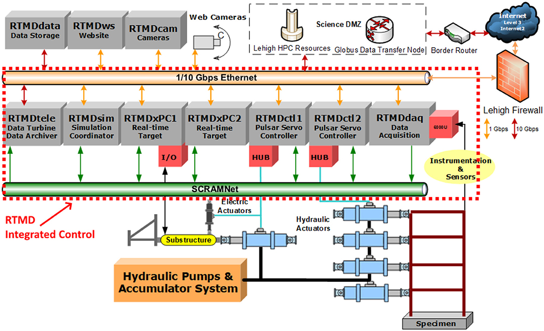
Figure 3. NHERI Lehigh EF real-time integrated control system.
The Real-Time Integrated Control System uses reflective memory, SCRAMNet GT, to enable communication among the telepresence server (RTMDtele), simulation coordinator (RTMDsim), real-time targets (RTMDxPC), servo-hydraulic controllers (RTMDctl), and data acquisition system (RTMDdaq). The data exchange across SCRAMNet GT occurs within 90 ns, enabling shared memory among the workstations and real-time testing capabilities. Synchronization is maintained on SCRAMNet GT at the real-time control rate of 1,024 Hz. Experiments can be run in real time (e.g., real-time hybrid simulations, distributed real-time hybrid simulations, dynamic testing) or at an expanded time scale (e.g., hybrid simulations, distributed hybrid simulations, quasi-static testing). When the Real-Time Integrated Control System is operated in distributed hybrid simulation mode, Matlab provides functions for creating TCP/IP sockets across the Internet with another client computer and is used as the interface to the Internet. The Integrated Control System is robust and has a flexible design, enabling software and middleware packages developed by the community to be adopted and utilized for conducting tests.
The algorithms necessary to control the test are implemented on the RTMDsim workstation and compiled on the RTMDxPC workstation. The algorithms are tailored specifically for each test and are programmed primarily with MathWorks (Mathworks, 1992). Simulink is used to design a model-in-the-loop system that is compiled and loaded on the RTMDxPC workstation. If an RTHS requires a large computational model with many degrees of freedom (DOFs) to create the analytical substructure, then the executable code is parallelized and placed onto two RTMDxPC workstations and run in a synchronous manner. For each time step of an RTHS, all of the calculations must be completed within the time step, which affects the size of the model and the maximum number of DOFs that can be used in the simulation. The maximum possible number of DOFs for an RTHS depends on the characteristics of the analytical substructure (e.g., type of elements, degree of non-linearity that occurs in the simulation and elements, complexities of the material model), the integration algorithm, the size of the time step for the simulation, and physical memory limitations of the software and hardware. In general, Simulink and Simulink Real-time can support up to 8,000 DOFs before running out of physical memory when performing a traditional matrix multiplication.
The RTMDctl workstations operate tunable closed-loop PID control algorithms for each actuator and have I/O controls for managing the hydraulic power system. The servo controller utilizes both software programmable limit states and physical limit switches on equipment to ensure the safety of personnel and equipment during operation. Emergency stops are located at each workstation and at various locations in the laboratory for quick access in case an emergency arises.
The integrated control system has a hydraulics-off simulation mode for use in validation of testing methods, training, and education. In the hydraulics-off simulation mode, the servo-hydraulic equipment (e.g., servo-actuators, servo-valves) and test structure are analytically modeled. Models of the servo-hydraulic equipment have been developed in Simulink for this purpose and have been calibrated based on system identification tests of the equipment.
The RTMDtele, RTMDws, and RTMDcam workstations provide a multimedia perspective into an experiment. Data located on SCRAMNet GT are presentable locally and remotely through the RTMDtele workstation Data Turbine application as a web interface via the RTMDws workstation, allowing for real-time plots and time seeking of data at any point of the experiment. Data can be analyzed and exported either during or after a test. The RTMDcam workstation organizes and synchronizes all of the video channels and provides a grid-based system for video observation to local and remote users. Video recording and image capture can be triggered by various methods depending on the user's requirements.
All data generated and captured is archived on the RTMDdata Synology system. Dual-redundancy data safeguards are implemented to ensure the reliability and security of the data. Data are organized for each experiment, and user permissions are designated per the requirements of the project team. Data related to NHERI projects are automatically synchronized daily with project space in the DesignSafe-CI project warehouse through https://www.globus.org/.
3.2. Real-Time Telepresence
Real-time telepresence is available for remote users. Teleobservation and teleoperation equipment (RTMDtele) are connected to an experiment using discrete and global sensors. The real-time visualization of the response of the complete system, including analytical and experimental substructures that exist in a hybrid simulation, is achieved using real-time structural system animation software. The experimental protocol includes the use of the Lehigh Data Model (Lee et al., 2008), which enables post-testing use of archived data from a hybrid simulation.
4. NHERI Lehigh EF RTHS Protocols
Real-time hybrid simulation (RTHS) is a cost-effective method for performing experimental validation of natural hazard mitigation strategies for civil infrastructure systems. Typically, a structural system in an RTHS is divided into two different substructures: (1) an analytical substructure where structural components with well-understood behavior are numerically modeled on the computer; and (2) an experimental substructure where complex components in the structural system for which there are no accurate numerical models are physically modeled in the laboratory. The two substructures are kinematically linked together via a simulation coordinator in order that the demand imposed on the structural system is correctly represented by that imposed on the two substructures. The overall concept is demonstrated in Figure 4 by using the example of a tall building equipped with passive dampers. Non-linear passive viscous dampers are installed in outrigger trusses of a 40-story steel frame building to improve its performance against wind and earthquake excitations. The structural components, which include the steel frames, associated seismic mass, and inherent damping, are modeled numerically as part of the analytical substructure, and the non-linear viscous dampers are physically modeled in the laboratory as the experimental substructure. Earthquake loads are determined from the accelerograms of ground motions. If an RTHS were to be performed where the building is instead subjected to a wind hazard, the wind load could be obtained from a wind tunnel test (e.g., at the NHERI FIU or UF EF). The equations of motion for the system are written:
where and are the acceleration and velocity vectors of the system at time ti+1, respectively, and are the restoring forces of the analytical and experimental substructures, respectively, at time ti+1, is the excitation force vector at time ti+1, and M and C are the analytically defined mass and inherent damping matrices of the system, respectively.
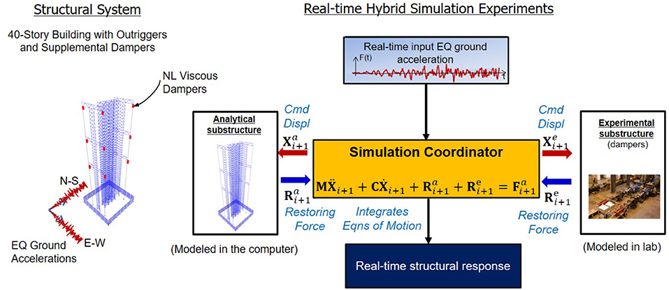
Figure 4. Overall concept of real-time hybrid simulation: structural system subject to seismic ground motions.
For a given time step ti+1, the simulation coordinator in Figure 4 solves Equation (1) using an explicit integration algorithm in real time. For the applied loading , the algorithm generates command displacements and for the analytical and experimental substructures, respectively. The command displacements are imposed on the experimental substructure (e.g., non-linear viscous dampers) in real time using servo-hydraulic actuators, while, simultaneously, the command displacements are applied to the analytical substructure. The restoring forces and from the analytical and experimental substructures are obtained, sent back to the simulation coordinator, and subsequently used to obtain the acceleration to complete the tasks for the time step. The simulation coordinator then advances to the next time step, and the process is repeated. Upon reaching the end of the loading history, the simulation is completed, and the real-time response obtained.
RTHS is performed at the NHERI Lehigh EF using explicit model-based dissipative integration algorithms developed by the authors (Chen and Ricles, 2008; Kolay and Ricles, 2014, 2019; Kolay et al., 2015). These algorithms are explicit and unconditionally stable. They do not require iteration to satisfy the equilibrium of Equation (1) and are ideal for conducting RTHS. The integration algorithm used in the examples described herein is the MKR-α integration algorithm (Kolay and Ricles, 2019). The MKR-α method features controlled numerical energy dissipation and controlled overshoot.
The analytical substructure for an RTHS is created using a suite of finite element programs developed by the authors (Kolay et al., 2018; Ricles et al., 2020b), termed HybridFEM-MH and HyCoM-3D. HybridFEM-MH and HyCoM-3D are similar, where the former is a multi-hazard 2D non-linear structural system response simulation program for assessing the performance of civil infrastructure systems, while the latter a 3D simulation program. Both programs are MATLAB- and Simulink-based. The source code is compiled and run in real time. The explicit-formulated element library in the programs includes non-linear fiber elements, non-linear truss elements, non-linear geometric elements to model P-Δ effects, non-linear hysteretic connection elements, non-linear panel zone elements, and zero-length elements, along with a material library that enables the hysteretic stress-strain behavior of steel, concrete, steel reinforcement, and zero-tension, zero-compression materials to be modeled. The programs also feature reduced-order elements, real-time model updating, and multi-point constraint options. User-defined elements can also be readily added to both programs. The programs have been successfully used to conduct non-linear time history analysis and RTHS of complex non-linear structural systems (Chen et al., 2008, 2009; Karavasilis et al., 2011, 2012; Chen and Ricles, 2012; Chae et al., 2014; Dong et al., 2015, 2016, 2018a,b; Kolay et al., 2015, in press; Al-Subaihawi et al., 2020).
An advanced adaptive delay compensation algorithm developed by the author (Chae et al., 2013a), termed the adaptive time series (ATS) compensator, is used to accurately achieve the target displacements associated with the command displacements of the experimental substructure in real time. The algorithm uses feedback signals from the measured state of the experimental specimen and minimizes displacement errors in an adaptive manner to ensure that the experimental substructure target displacements are accurately achieved.
For multi-directional experiments, a kinematic compensation testing protocol based on an algorithm developed by the authors (Mercan et al., 2009) is used to avoid kinematic errors during a test. The algorithm accounts for the displaced configuration of the test structure and the actuators, and the non-linear relationship between the target displacements, displaced configuration of the test structure, and the actuators, in determining the actuator command displacement signals issued to the servo-controller (RTMDctrl).
5. Example Research Projects
In this section, five selected example projects performed by researchers that have utilized the NHERI Lehigh EF are presented.
5.1. Large-Scale RTHS of a Three-Story Steel Frame Building Equipped With Magneto-Rheological Dampers
The seismic response of a 3-story, 6-bay by 6-bay office building located in Southern California, equipped with magneto-rheological (MR) dampers was investigated by Chae et al. (2014) using the RTHS method. The building's lateral force-resisting system consists of steel moment-resisting frames (MRFs) with reduced beam section (RBS) beam-to-column connections and damped braced frames (DBF) with MR dampers, as shown in Figure 5.
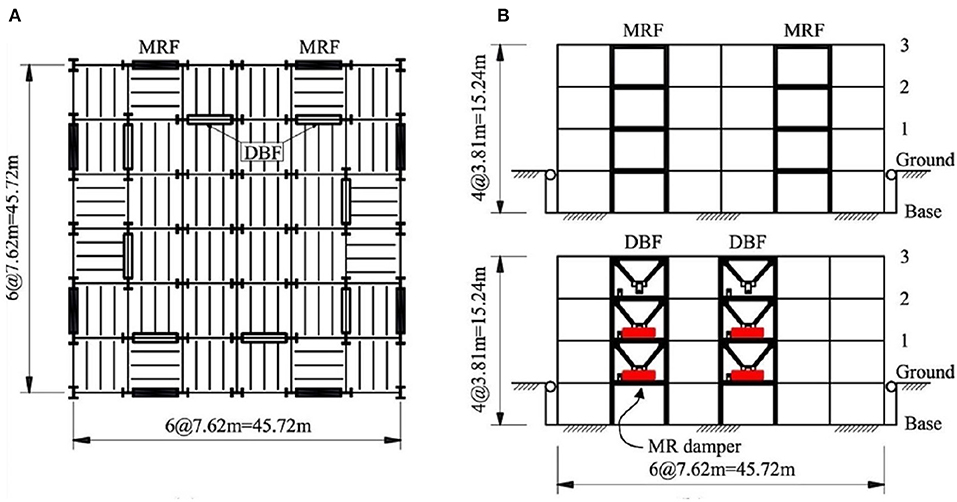
Figure 5. Three-story building: (A) plan view and (B) elevation (reprinted from Chae et al., 2014 with permission).
A 0.6-scale three-story DBF installed with two MR dampers was fabricated at the NHERI Lehigh EF and represented the experimental substructure for the RTHS. The DBF was braced out of plane by the lateral load-resisting system testbed at each floor, and the floor beams in the DBF were connected to the columns by a bolted T-section connection, as shown in Figure 6A. Two MR dampers were installed in the first and second stories through clevises and diagonal bracing. Each MR damper has a 200-kN capacity, a stroke of 558 mm, and a maximum piston velocity of 100 mm/s under a current input of 2.5 A. To conduct the RTHS test, 2,300 kN servo-hydraulic actuators were attached to the first and second floors of the DBF, and a 1,700-kN servo-hydraulic actuator was attached to the third floor (Figure 6B). The remaining parts of the building, including the MRF, gravity load system, and the tributary seismic floor masses, were modeled via the analytical substructure, as shown in Figure 6C.
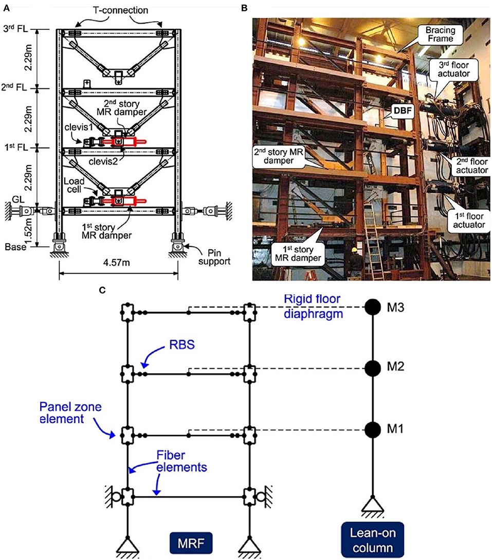
Figure 6. RTHS of a three-story building with MR dampers: (A) schematic of the experimental substructure, (B) photograph of the experimental test setup, and (C) analytical substructure (reprinted from Chae et al., 2014 with permission).
The RTHS study focused on evaluating the seismic performance of the building when using the MR dampers in semi-active control mode. Two ground motions, namely, the 1992 Landers earthquake and the 1994 Northridge earthquake, were used and scaled to 60 and 80% of the design basis earthquake (DBE) level. The RTHS results show that maximum story drifts are reduced by 44 and 14% under the 1992 Landers earthquake and the 1994 Northridge earthquake, respectively, when using MR dampers with an LQR control law. Data from the RTHS were used to develop a computational model for an MR damper (Chae et al., 2013c). Comparisons between numerical simulations using the MR damper model and RTHS results under the 80% DBE hazard level of the 1994 Northridge earthquake show good agreement, as shown in Figure 7.
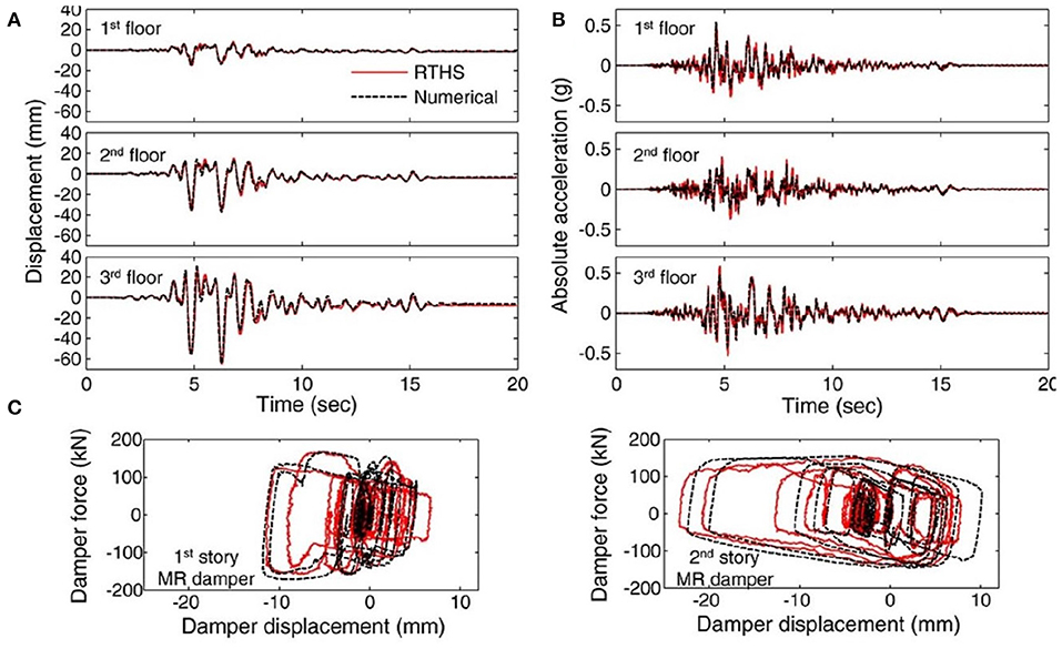
Figure 7. Comparison between numerical simulation and RTHS results under the 80% DBE level 1994 Northridge earthquake: (A) floor displacement, (B) floor absolute acceleration, and (C) force-displacement response of MR dampers (reprinted from Chae et al., 2014 with permission).
5.2. Large-Scale RTHS of a Reduced-Strength Steel Building With Non-linear Viscous Dampers Subject to Strong Ground Motions
The performance of the three-story steel frame building equipped with non-linear viscous dampers subjected to strong ground motions was investigated by Dong et al. (2018b) using real-time hybrid simulations. The same building's lateral force-resisting system from the previous subsection (Figure 5) was used except that the damped braced frames (DBF) were equipped with non-linear viscous dampers at three floors. Unlike the previous RTHS substructure, the analytical substructure used in this study included only the seismic mass and gravity load system (Figure 8A). The MRF and DBF with non-linear viscous dampers were physically modeled via the experimental substructure; see Figure 8B. The test setup for the experimental substructure is shown in Figure 8C.
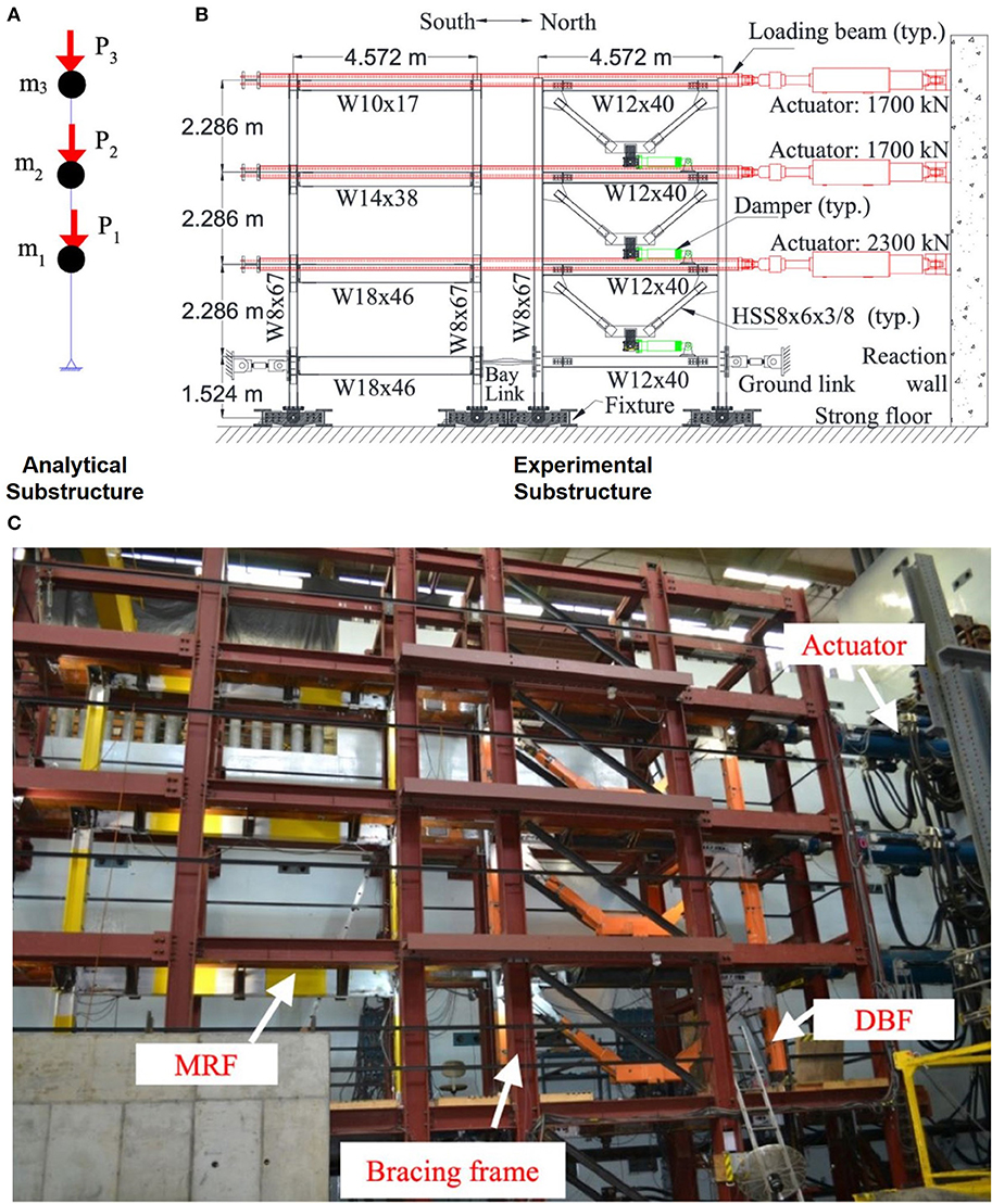
Figure 8. RTHS substructures of a three-story building equipped with non-linear viscous dampers: (A) analytical substructure, (B) experimental substructure, and (C) experimental test setup (reprinted from Dong et al., 2018b with permission).
Three MRF designs were studied, where the MRF was designed for 100, 75, and 60% of the required design base shear according to ASCE 7-10 (ASCE, 2010). The objective was to assess the seismic performance of MRFs designed with reduced strength and added supplemental damping. Four hazard levels were considered for the RTHS, specifically DBE, maximum considered earthquake (MCE), and two earthquakes scaled to hazard levels beyond the MCE level (1.2 and 1.4 MCE). The peak story drift results of the building with the 60% design base shear strength MRF under the 1979 Imperial Valley earthquake were found to be <1.4% under the DBE and to satisfy the “Life Safety” performance level of 2.5% under the MCE and the “Collapse Prevention” performance level of 5% for both 1.2 and 1.4 MCE. The RTHS results demonstrated good performance of the prototype building with a 60% design base shear strength when subjected to strong ground motions, including intensity levels beyond the MCE level. The researcher concluded that buildings can be designed using supplemental dampers with a reduced strength that is lower than that which the code permits for seismic hazards (Dong et al., 2018b).
5.3. 3D RTHS of Tall Buildings Equipped With Non-linear Viscous Dampers Subject to Multi-Natural Hazards
The damped outriggers system for tall buildings aims at placing dampers vertically between the outrigger truss and the perimeter columns as a means of increasing the equivalent damping of the building (Smith and Willford, 2007). When the outrigger truss ends move relative to the perimeter columns, the dampers develop forces that suppress vibrations caused by lateral loading.
The building is shown in Figure 9 and is assumed to be located in Los Angeles, California. It was designed by Simpson Gumpertz & Heger Inc. as part of the PEER Tall Building Initiative (Moehle et al., 2011). The building is 166-m tall measured from the ground level, with 40 stories above grade and four basement levels. Six buckling restrained braced frames (BRBFs) provide the lateral force-resisting systems in each of the North-South and East-West directions. Outrigger trusses are located at the 20th, 30th, and 40th stories. The original design of the building was modified by Kolay et al. (in press) to include non-linear viscous dampers (NLVDs) between the outriggers and the perimeter columns, as shown in Figure 9. Real-time hybrid simulations were used by Kolay et al. (in press) and Ricles et al. (2020a) to understand the behavior of the modified system when subjected to wind and earthquake hazards.
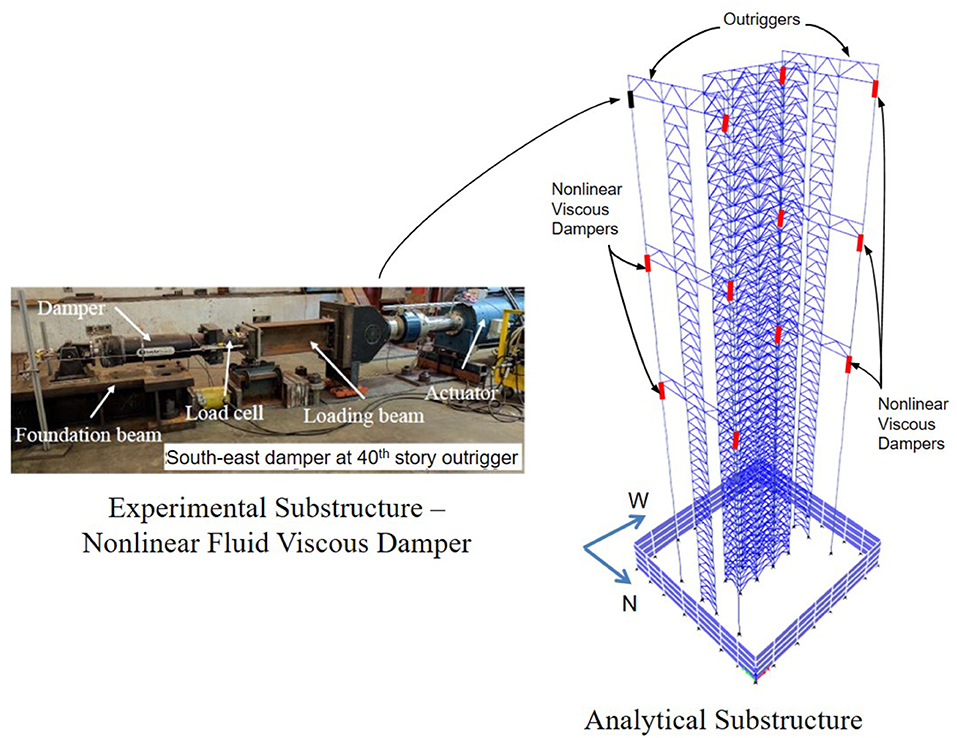
Figure 9. RTHS of a tall building equipped with a damped outriggers system; numerically and physically modeled dampers are marked in red and black, respectively.
The analytical substructure for the RTHS included a total of 2,411 elastic beam-column elements to model the beams and columns and 552 non-linear truss elements to model the buckling restrained braces (BRBs). The total number of degrees of freedom in the model for the RTHS is 3974, allowing the equations of motion to be integrated in real time with an integration time step of 11/1,024 s. The analytical model is developed using HyCoM-3D (Ricles et al., 2020b) to perform 3D RTHS with bi-directional loading.
Four non-linear dampers are placed between each outrigger truss and perimeter column, coming to a total of 48 dampers. One full-scale non-linear damper was considered as the experimental substructure for the RTHS and was placed at the South-East side of the 40th story outrigger, while the other dampers were modeled numerically using on-line model updating. The combined system (analytical and experimental) was subjected to natural hazards consisting of an earthquake scaled to the Maximum Considered Earthquake hazard level and a windstorm with a 177 km/hr windspeed acting in the East-West direction and associated cross-wind effects acting in the North-South direction. The windstorm forces are obtained from wind tunnel tests performed in the wind tunnel facility at Tokyo Polytechnic University (Tokyo Polytechnic University, 2017).
Figures 10, 11 show the response of the building under the two natural hazards. Building response was non-linear under earthquake, as characterized by inelastic deformations in the BRBs at several story levels. The period of the first translational mode in the North-South direction was 6.3 s, while that in the East-West direction was 4.3 s (obtained via an eigenvalue analysis using a linearized damper model). More damage in the building is observed in the East-West direction (Figure 10D) despite its higher stiffness compared to the North-South direction (Figure 10C) because of the characteristics of the ground motion, which impose higher spectral accelerations and correspondingly higher inertial forces in the East-West direction. The response of the experimental substructure in Figure 10E is characterized by a wide hysteresis loop because of the non-linear response of the damper at high velocities, which limits the rate at which the damping force increases as the damper force becomes capped and limited in magnitude (Lin and Chopra, 2002).
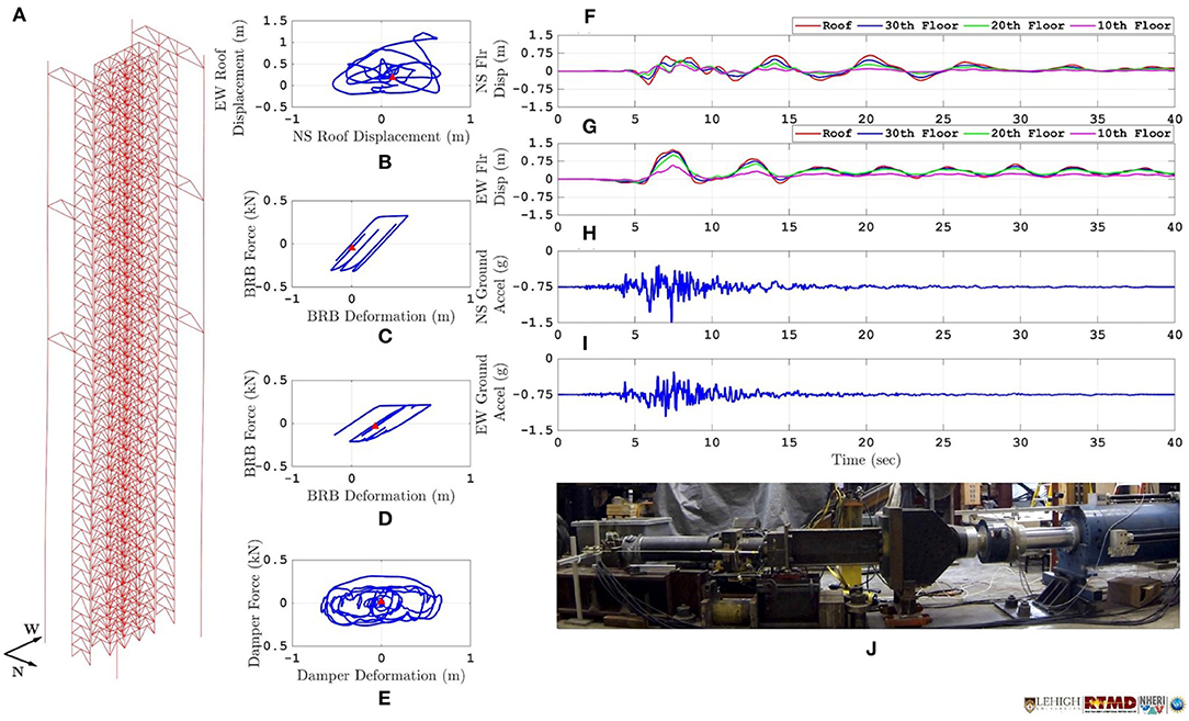
Figure 10. The 3D RTHS of a tall building equipped with non-linear viscous dampers under seismic excitation: (A) isometric view of structure, (B) bi-directional roof displacement orbits, (C,D) 1st story brace hysteresis in the NS and EW directions, (E) force-displacement hysteresis of the NLVD experimental substructure, (F,G) floor displacement time histories of selected floor levels, (H,I) bi-directional ground accelerations, and (J) experimental substructure (full-scale NLVD).
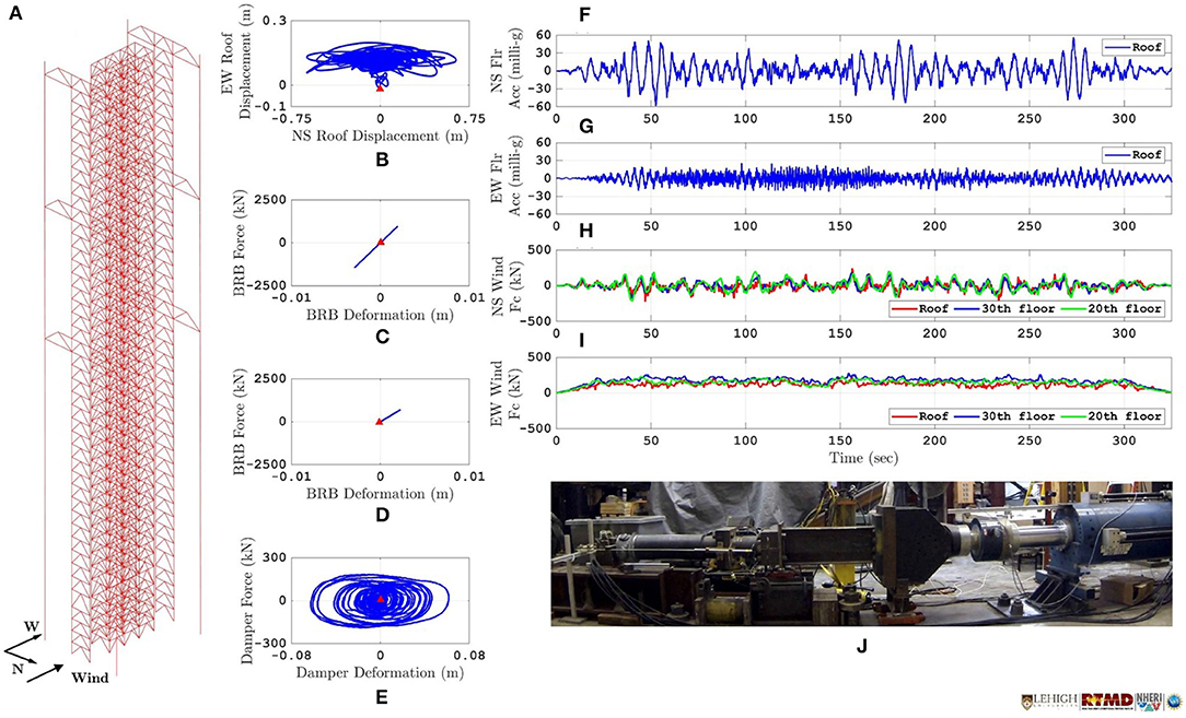
Figure 11. The 3D RTHS of a tall building equipped with non-linear viscous dampers under wind excitation: (A) isometric view of structure, (B) bi-directional roof displacement orbits, (C,D) 1st story brace hysteresis in the NS and EW directions, (E) force-displacement hysteresis of the NLVD experimental substructure, (F,G) floor displacement time histories of selected floor levels, (H,I) bi-directional wind loading at selected floor levels, and (J) experimental substructure (full-scale NLVD).
The building response was linear under the windstorm. As described earlier, the building is less stiff in the North-South direction, so it undergoes a higher peak roof displacement in that direction (Figure 11B) despite the fact that vortex shedding is imposing peak floor forces in the North-South direction that are comparable to wind forces in the East-West direction (Figures 11H,I). The flexibility of the building in the North-South direction makes it more susceptible to wind-induced vibrations, and thus adding dampers in the North-South direction helps control the floor accelerations in that direction. The damper response under wind differs from that under earthquake loading, which is characterized by elliptically shaped hysteresis in the damper force-displacement plot (see Figure 11E). The results of this study show that for large complex structures, the RTHS can capture the rate dependency of the experimental substructure depending on the natural hazard imposed.
5.4. Characterization of a Novel Semi-active Friction Device Based on Band Brake Technology
A new semi-active friction damper using band brake technology, termed the Banded Rotary Friction Damper (BRFD), has been developed by Downey et al. (2016). The damping mechanism is based on band brake technology and leverages the self-energizing mechanism to produce large damping forces using low input force. It consists of three flexible braking bands lined with friction material that tightens concentrically around a cylindrical drum to slow or stop its rotation. One inner band is attached to a screw-type actuation mechanism consisting of a threaded rod for the purpose of varying the force applied (Fapplied) to the band brake, and two outer bands are anchored to a rigid frame. The BRFD produces a variable braking torque as a linear function of the input force.
The dynamic behavior of the BRFD was investigated through characterization tests performed at the NHERI Lehigh Real-Time Cyber-Physical Structural Systems Laboratory. A one-third-scale BRFD was connected to an MTS actuator via a clevis, and the damping force was recorded by the actuator load cell. The applied input force Fapplied was achieved using force feedback signals from a load cell placed in the BRFD.
The prototype was subjected to a displacement-controlled harmonic excitation of a 25.4-mm amplitude with a frequency of 0.5 Hz. Three different values of constant Fapplied were investigated: 222, 267, and 311 N. The BRFD force-displacement and force-velocity responses are plotted in Figure 12, where the results show that the prototype BRFD is capable of obtaining a damping force of 22.2 kN using an input force of Fapplied = 311 N, resulting in a force amplification ratio (FAR) of 72. The FAR is defined as the ratio of BRFD force output to actuator force input.
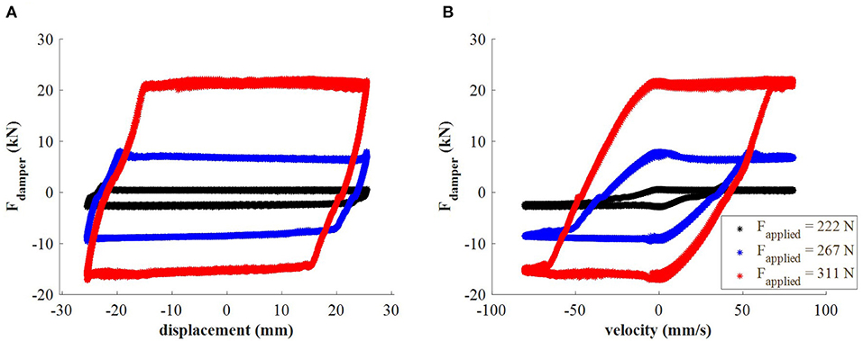
Figure 12. Characterization tests of BRFD under harmonic testing at 0.5 Hz: (A) damper force-displacement response and (B) damper force-velocity response.
5.5. Multi-Directional Dynamic Testing of Cross-Laminated Timber Self-Centering Coupled Walls-Floor Diaphragm-Gravity System
Cross-laminated timber (CLT) is an engineered-wood structural component fabricated by laminating layers of timber boards in an orthogonal pattern glued together on their wide face. A self-centering (SC) rocking post-tensioned CLT structural wall (SC-CLT walls) has been proposed recently and its experimental response under unidirectional cyclic loadings was studied by Akbas et al. (2017). However, the dynamic behavior of SC-CLT rocking walls under bidirectional loading and its performance coupled with wood structures have not been investigated.
To fill this knowledge gap, Sause et al. (2020) recently conducted multi-directional quasi-static testing with predefined displacement at the NHERI Lehigh EF on a CLT-floor diaphragm-gravity system with an SC-CLT rocking wall. Figure 13A shows the schematic of the CLT-floor diaphragm-gravity system, and Figure 13B shows a photograph of the shear wall and CLT test setup. The system consists of a 0.625-scale subassembly of a self-centering coupled CLT floor diaphragm, three glulam gravity beams, two glulam collector beams, and five glulam gravity columns. The glulam collector beams transfer the lateral force from the CLT floor diaphragm to the SC-CLT walls through a slotted connection, and two U-shaped flexural plates (UFP) are embedded between the SC-CLT rocking wall to dissipate energy. Four servo-hydraulic actuators are used to impose the bi-directional motion on the system subassembly (two in the in-plane direction and two in the out-of-plane direction). A kinematic compensation algorithm developed by the authors (Mercan et al., 2009) was used to perform the multi-directional test. A structure-physical node (SPN) located at the center of the SC-CLT wall was used as the test specimen control node associated with the subassembly degrees of freedom. Two measurement-structural nodes (MSN) located on the CLT floor diaphragm were used to measure the floor displacement. The degrees of freedom relationship between the SPN and MSN was established via the compensation algorithm, and the SPN displacement is controlled using real-time continuous displacement feedback from the two MSNs. The multi-directional quasi-static cyclic test was performed, and the bi-directional target and measured subassembly drifts of the SPN are compared in Figure 14A. Comparing the targeted and measured SPN drift, the normalized root mean square error (NRMSE) of drifts for the in-plane (SPNX) and out-of-plane directions (SPNY) were calculated and were equal to 0.127 and 0.044%, indicating that a high degree of accuracy was achieved for specimen displacement.
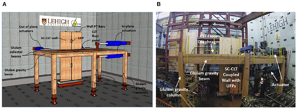
Figure 13. Multi-directional test of cross-laminated timber self-centering coupled walls-floor diaphragm-gravity system: (A) schematic and (B) test setup (courtesy of Amer, 2021).
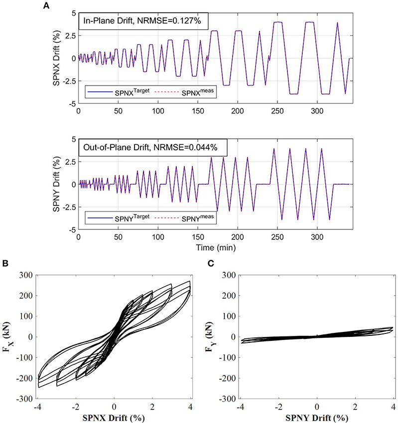
Figure 14. Multi-directional test of cross-laminated timber self-centering coupled walls-floor diaphragm gravity system: (A) comparison of target drift and measured subassembly drift, (B) in-plan lateral load-story drift response, and (C) out-of-plane lateral load-story drift response (courtesy of Amer, 2021).
The in-plane and out-of-plane lateral load-story drift response are shown in Figures 14B,C. FX and FY represent the in-plane and out-of-plane applied lateral loads, respectively. The results show that energy dissipation occurs from the UFPs. In addition, the in-plane capacity is greater than the out-of-plane capacity due to the wall geometry, and the walls exhibit a self-centering behavior. Some deterioration is observed to occur under the cyclic loading, which is exacerbated by damage caused to the CLT outer plies by the out-of-plane imposed drift. This work is still in progress, with more testing planned by Amer (2021).
6. Summary and Conclusions
The infrastructure and capabilities of the Natural Hazards Engineering Research Infrastructure Lehigh Experimental Facility were presented. The facility is an open-access facility that enables researchers to conduct state-of-art research on natural hazard mitigation for civil infrastructure systems. The facility has the unique ability to conduct 3D large-scale multi-directional real-time hybrid simulations and testing involving large-scale physical structural and non-structural components. Several testing protocols are enabled at the facility, including (1) large-scale hybrid simulation, (2) large-scale real-time hybrid simulation, (3) large-scale RTHS with multiple experimental substructures, (4) geographically distributed hybrid simulation, (5) geographically distributed real-time hybrid earthquake simulation, (6) dynamic testing, and (7) quasi-static testing. The unique portfolio of experimental equipment, instrumentation, testbeds, and testing protocols that exist at the NHERI Lehigh EF was presented. Various testbeds including a lateral load-resisting system testbed, a non-structural component multi-directional dynamic loading simulator, full-scale and reduced-scale damper testbeds, a tsunami and storm surge debris impact force testbed, and a soil-foundation structure interaction testbed were described and are available for a wide range of research.
Several selected example research projects recently performed at the NHERI Lehigh EF were introduced to illustrate the facility's capabilities. These projects included (1) large-scale RTHS of a three-story steel frame building equipped with magneto-rheological (MR) dampers subject to strong earthquake ground motions, (2) large-scale RTHS of a reduced-strength steel frame building with non-linear viscous dampers subject to strong earthquake ground motions, (3) 3D multi-hazard large-scale RTHS of tall steel buildings subject to multi-directional wind and earthquake ground motions, (4) characterization testing of a novel friction device based on band brake technology, and (5) testing of a cross-laminated timber self-centering coupled walls-floor diaphragm-gravity system involving multi-directional loading. All test results and research data are shared through the NHERI DesignSafe (https://www.designsafe-ci.org/data/browser/public/).
More information about the NHERI Lehigh EF can be found at the facility's website at https://lehigh.designsafe-ci.org/facility/overview/. This information includes the facility overview, equipment portfolio, experimental protocols, projects, resources, facility outreach, and contact information.
Data Availability Statement
The raw data supporting the conclusions of this article will be made available by the authors, without undue reservation, to any qualified researcher.
Author Contributions
All authors listed have made a substantial, direct and intellectual contribution to the work, and approved it for publication.
Funding
The research reported in this paper was supported by several grants from the National Science Foundation (NSF). This included Award No. CMMI-0936610 NEESR-CR: Performance-Based Design for Cost-Effective Seismic Hazard Mitigation in New Buildings Using Supplemental Passive Damper Systems, Award No. CMMI 0830173 NEESR-SG: Performance-Based Design and Real-Time Large-Scale Testing to Enable Implementation of Advanced Damping Systems, CMMI Award No. 1463497 Collaborative Research: Semi-Active Controlled Cladding Panels for Multi-Hazard Resilient Buildings, Award No. CMS-1635227 Collaborative Research: A Resilience-based Seismic Design Methodology for Tall Wood Buildings, and Award No. CMS-0402490 NEES Consortium Operation. The research reported in this paper was performed at the NHERI Lehigh Large-Scale Multi-Directional Hybrid Simulation Experimental Facility. Financial support for the operation of the NHERI Lehigh Large-Scale Multi-Directional Hybrid Simulation Experimental Facility was provided by NSF under Cooperative Agreement No. CMMI-1520765.
Conflict of Interest
The authors declare that the research was conducted in the absence of any commercial or financial relationships that could be construed as a potential conflict of interest.
Acknowledgments
The authors were grateful for the support of the National Science Foundation (NSF) and additional financial support provided by the Pennsylvania Infrastructure Technology Alliance (PITA) and Lehigh University. The authors would like to thank several former staff members and researchers who contributed to the developments that led to advancements in the NHERI Lehigh capabilities. These include Dr. Oya Mercan, former NEES Lehigh Research Scientist and currently Associate Professor at the University of Toronto, Dr. Cheng Chen, former NEES Lehigh Research Scientist and currently Associate Professor at San Francisco State University, Dr. Baiping Dong, currently Research Scientist at Tongji University, Dr. Yunbyeong Chae, currently Associate Professor at Old Dominion University, and Dr. Theodore Karavasilis, currently Associate Professor at Patras University. Their contributions were greatly valued and readily utilized by the NHERI Lehigh Experimental Facility. Any opinions, findings, and conclusions expressed in this paper are those of the authors and do not necessarily reflect the views of the sponsors (the NSF, PITA, and Lehigh University) acknowledged herein.
References
Akbas, T., Sause, R., Ricles, J. M., Ganey, R., Berman, J., Loftus, S., et al. (2017). Analytical and experimental lateral-load response of self-centering posttensioned clt walls. J. Struct. Eng. 143:04017019. doi: 10.1061/(ASCE)ST.1943-541X.0001733
Al-Subaihawi, S., Kolay, C., Marullo, T., Ricles, J. M., and Quiel, S. E. (2020). Assessment of wind-induced vibration mitigation in a tall building with damped outriggers using real-time hybrid simulations. Eng. Struct. 205:110044. doi: 10.1016/j.engstruct.2019.110044
Amer, A. (2021). Experimental and numerical study of seismically resilient wood buildings with self-centering clt shear walls (Ph.D. dissertation), Department of Civil and Environmental Engineering, Lehigh University, Bethlehem, PA, United States.
ASCE (2010). Minimum Design Loads for Buildings and Other Structures. ASCE/SEI 7-10 edition. Reston, VA: American Socitey of Civil Engineering.
Cao, L., Downey, A., Laflamme, S., Taylor, D., and Ricles, J. (2015). Variable friction device for structural control based on duo-servo vehicle brake: modeling and experimental validation. J. Sound Vib. 348, 41–56. doi: 10.1016/j.jsv.2015.03.011
Chae, Y., Kazemibidokhti, K., and Ricles, J. M. (2013a). Adaptive time series compensator for delay compensation of servo-hydraulic actuator systems for real-time hybrid simulation. Earthq. Eng. Struct. Dyn. 42, 1697–1715. doi: 10.1002/eqe.2294
Chae, Y., Ricles, J. M., and Sause, R. (2013b). Modeling of a large-scale magneto-rheological damper for seismic hazard mitigation. Part I: passive mode. Earthq. Eng. Struct. Dyn. 42, 669–685. doi: 10.1002/eqe.2237
Chae, Y., Ricles, J. M., and Sause, R. (2013c). Modeling of a large-scale magneto-rheological damper for seismic hazard mitigation. Part II: semi-active mode. Earthq. Eng. Struct. Dyn. 42, 687–703. doi: 10.1002/eqe.2236
Chae, Y., Ricles, J. M., and Sause, R. (2014). Large-scale real-time hybrid simulation of a three-story steel frame building with magneto-rheological dampers. Earthq. Eng. Struct. Dyn. 43, 1915–1933. doi: 10.1002/eqe.2429
Chen, C., and Ricles, J. M. (2008). Development of direct integration algorithms for structural dynamics using discrete control theory. J. Eng. Mech. 134, 676–683. doi: 10.1061/(ASCE)0733-9399(2008)134:8(676)
Chen, C., and Ricles, J. M. (2012). Large-scale real-time hybrid simulation involving multiple experimental substructures and adaptive actuator delay compensation. Earthq. Eng. Struct. Dyn. 41, 549–569. doi: 10.1002/eqe.1144
Chen, C., Ricles, J. M., Hodgson, I. C., and Sause, R. (2008). “Real-time multi-directional hybrid simulation of building piping systems,” in Proceedings of the 14th World Conference on Earthquake Engineering (Beijing).
Chen, C., Ricles, J. M., Marullo, T. M., and Mercan, O. (2009). Real-time hybrid testing using the unconditionally stable explicit CR integration algorithm. Earthq. Eng. Struct. Dyn. 38, 23–44. doi: 10.1002/eqe.838
Dong, B., Sause, R., and Ricles, J. (2018a). “Seismic performance of steel MRF structures with nonlinear viscous dampers from real-time hybrid simulations,” in Proceedings of the 9th International Conference on Behavior of Steel Structures in Seismic Areas (STESSA) (Christchurch).
Dong, B., Sause, R., and Ricles, J. M. (2015). Accurate real-time hybrid earthquake simulations on large-scale mdof steel structure with nonlinear viscous dampers. Earthq. Eng. Struct. Dyn. 44, 2035–2055. doi: 10.1002/eqe.2572
Dong, B., Sause, R., and Ricles, J. M. (2016). Seismic response and performance of a steel MRF building with nonlinear viscous dampers under DBE and MCE. J. Struct. Eng. 142:04016023. doi: 10.1061/(ASCE)ST.1943-541X.0001482
Dong, B., Sause, R., and Ricles, J. M. (2018b). Seismic response and damage of reduced-strength steel MRF structures with nonlinear viscous dampers. J. Struct. Eng. 144:04018221. doi: 10.1061/(ASCE)ST.1943-541X.0002226
Downey, A., Cao, L., Laflamme, S., Taylor, D., and Ricles, J. (2016). High capacity variable friction damper based on band brake technology. Eng. Struct. 113, 287–298. doi: 10.1016/j.engstruct.2016.01.035
Karavasilis, T. L., Ricles, J. M., Sause, R., and Chen, C. (2011). Experimental evaluation of the seismic performance of steel MRFs with compressed elastomer dampers using large-scale real-time hybrid simulation. Eng. Struct. 33, 1859–1869. doi: 10.1016/j.engstruct.2011.01.032
Karavasilis, T. L., Sause, R., and Ricles, J. M. (2012). Seismic design and evaluation of steel moment-resisting frames with compressed elastomer dampers. Earthq. Eng. Struct. Dyn. 41, 411–429. doi: 10.1002/eqe.1136
Kim, S. J., Christenson, R., Phillips, B., and Spencer, B. Jr. (2012). “Geographically distributed real-time hybrid simulation of MR dampers for seismic hazard mitigation,” in Proceedings of the 20th Analysis and Computation Specialty Conference (Chicago, IL), 382–393. doi: 10.1061/9780784412374.034
Kolay, C., Al-Subaihawi, S., Marullo, T., Ricles, J., and Quiel, S. (in press). Multi-hazard real-time hybrid simulation of a tall building with damped outriggers. Int. J. Lifecycle Perform. Eng.
Kolay, C., Marullo, T., and Ricles, J. (2018). HybridFEM-MH: A Program for Nonlinear Dynamic Analysis and Real-Time Hybrid Simulation of Civil Infrastructure Systems Subject to Multi-Hazards. Technical Report ATLSS Report No. 18-06. Bethlehem, PA: ATLSS Engineering Research Center, Lehigh University.
Kolay, C., and Ricles, J. M. (2014). Development of a family of unconditionally stable explicit direct integration algorithms with controllable numerical energy dissipation. Earthq. Eng. Struct. Dyn. 43, 1361–1380. doi: 10.1002/eqe.2401
Kolay, C., and Ricles, J. M. (2019). Improved explicit integration algorithms for structural dynamic analysis with unconditional stability and controllable numerical dissipation. J. Earthq. Eng. 23, 771–792. doi: 10.1080/13632469.2017.1326423
Kolay, C., Ricles, J. M., Marullo, T. M., Mahvashmohammadi, A., and Sause, R. (2015). Implementation and application of the unconditionally stable explicit parametrically dissipative KR-α method for real-time hybrid simulation. Earthq. Eng. Struct. Dyn. 44, 735–755. doi: 10.1002/eqe.2484
Lee, C.-H., Chin, C. H., Marullo, T., Bryan, P., Sause, R., and Ricles, J. M. (2008). Data model for large-scale structural experiments. J. Earthq. Eng. 12, 115–135. doi: 10.1080/13632460701299120
Lee, K.-S., Fan, C.-P., Sause, R., and Ricles, J. (2005). Simplified design procedure for frame buildings with viscoelastic or elastomeric structural dampers. Earthq. Eng. Struct. Dyn. 34, 1271–1284. doi: 10.1002/eqe.479
Lin, W.-H., and Chopra, A. K. (2002). Earthquake response of elastic sdf systems with non-linear fluid viscous dampers. Earthq. Eng. Struct. Dyn. 31, 1623–1642. doi: 10.1002/eqe.179
Lin, Y.-C., Sause, R., and Ricles, J. M. (2013). Seismic performance of steel self-centering, moment-resisting frame: hybrid simulations under design basis earthquake. J. Struct. Eng. 139, 1823–1832. doi: 10.1061/(ASCE)ST.1943-541X.0000745
Mercan, O., Ricles, J. M., Sause, R., and Marullo, T. (2009). Kinematic transformations for planar multi-directional pseudodynamic testing. Earthq. Eng. Struct. Dyn. 38, 1093–1119. doi: 10.1002/eqe.886
Moehle, J., Bozorgnia, Y., Jayaram, N., Jones, P., Rahnama, M., Shome, N., et al. (2011). Case Studies of the Seismic Performance of Tall Buildings Designed by Alternative Means. Report 2011/05. Berkeley, CA: Pacific Earthquake Engineering Research Center, University of California.
Perez, F. J., Pessiki, S., and Sause, R. (2013). Experimental lateral load response of unbonded post-tensioned precast concrete walls. ACI Struct. J. 110, 1045–1056. doi: 10.14359/51686159
Ricles, J., Al-Subaihawi, S., Kolay, C., Marullo, T., Cao, L., and Quiel, S. (2020a). “Multi-natural hazard real-time hybrid simulation of tall buildings with nonlinear viscous dampers,” in Proceedings of the 17th World Conference on Earthquake Engineering (Sendai).
Ricles, J., Kolay, C., and Marullo, T. (2020b). HyCoM-3D: A Program for Multi-Hazard Nonlinear Dynamic Analysis and Real-Time Hybrid Simulation of 3-D Civil Infrastructural Systems. ATLSS Report No. 20-02. Bethlehem, PA: Lehigh Unversity.
Ricles, J., Marullo, T., and Roy, S. (2007). Multiple NEES Equipment Site Soil-Structure-Foundation Distributed Hybrid Simulations. ATLSS Report No. 07-12. Bethlehem, PA: Lehigh Unviersity.
Ricles, J. M., Fisher, J., Lu, L.-W., and Kaufmann, E. (2002a). Development of improved welded moment connections for earthquake-resistant design. J. Constr. Steel Res. 58, 565–604. doi: 10.1016/S0143-974X(01)00095-5
Ricles, J. M., Mao, C., Lu, L.-W., and Fisher, J. W. (2002b). Inelastic cyclic testing of welded unreinforced moment connections. J. Struct. Eng. 128, 429–440. doi: 10.1061/(ASCE)0733-9445(2002)128:4(429)
Riggs, H., Cox, D., Naito, C., Kobayashi, M., Aghl, P. P., Ko, H.-S., et al. (2014). Experimental and analytical study of water-driven debris impact forces on structures. J. Offshore Mech. Arctic Eng. 136:041603. doi: 10.1115/1.4028338
Sause, R., Ricles, J., Amer, A., and Marullo, T. (2020). “Multi-directional cyclic testing of cross-laminated timber rocking wall-floor diaphragm sub-assemblies,” in Procedings of the 17th World Conference on Earthquake Engineering (Sendai).
Smith, R. J., and Willford, M. R. (2007). The damped outrigger concept for tall buildings. Struct. Des. Tall Spec. Build. 16, 501–517. doi: 10.1002/tal.413
Suleiman, M. T., Ni, L., and Raich, A. (2014). Development of pervious concrete pile ground-improvement alternative and behavior under vertical loading. J. Geotech. Geoenviron. Eng. 140:04014035. doi: 10.1061/(ASCE)GT.1943-5606.0001135
Tokyo Polytechnic University (2017). Aerodynamic Database of High-Rise Buildings. Available online at: http://www.wind.arch.t-kougei.ac.jp/info_center/windpressure/highrise/Homepage/homepageHDF.htm (accessed February 16, 2017).
Keywords: large-scale experiments, real-time hybrid simulation, multi-directional, structural control, multi-hazard
Citation: Cao L, Marullo T, Al-Subaihawi S, Kolay C, Amer A, Ricles J, Sause R and Kusko CS (2020) NHERI Lehigh Experimental Facility With Large-Scale Multi-Directional Hybrid Simulation Testing Capabilities. Front. Built Environ. 6:107. doi: 10.3389/fbuil.2020.00107
Received: 11 February 2020; Accepted: 05 June 2020;
Published: 31 July 2020.
Edited by:
Marcial Blondet, Pontifical Catholic University of Peru, PeruReviewed by:
Wei Song, University of Alabama, United StatesPedro L. Fernández-Cabán, Clarkson University, United States
Copyright © 2020 Cao, Marullo, Al-Subaihawi, Kolay, Amer, Ricles, Sause and Kusko. This is an open-access article distributed under the terms of the Creative Commons Attribution License (CC BY). The use, distribution or reproduction in other forums is permitted, provided the original author(s) and the copyright owner(s) are credited and that the original publication in this journal is cited, in accordance with accepted academic practice. No use, distribution or reproduction is permitted which does not comply with these terms.
*Correspondence: Liang Cao, bGljNDE4QGxlaGlnaC5lZHU=