 Mariano Modano
 Arnas Majumder2
 Fernando Fraternali
- 1Department of Structures for Engineering and Architecture, University of Naples Federico II, Naples, Italy
- 2Department of Civil Engineering, University of Salerno, Fisciano, Italy
- 3CERIS and Departamento de Engenharia Civil, Faculdade de Ciências e Tecnologia da Universidade Nova de Lisboa, Caparica, Portugal
- 4Department of Engineering, University of Naples “Parthenope”, Naples, Italy
This paper presents with an effective and fast approach to the optimization of the pretension forces in arched bridges with suspended deck, which makes use of the influence matrix method (IMM). The given cable-tensioning procedure leads to a linear system of equations with a reduced number of unknowns and can be effectively implemented within active control procedures that handle time-varying loading conditions. This method produces a target bending moment distribution (TBMD) over the structure, which significantly mitigates the state of stress of the deck. Numerical simulations referred to a Nielsen arch bridge illustrate the versatility of the proposed approach when dealing with different loading conditions.
Introduction
There are several adaptive applications of cable-stayed structures in the field of bridge construction (Simões and Negrão, 1995; Freire et al., 2006; Fabbrocino et al., 2017; Song et al., 2018; Reksowardojo et al., 2019). An adaptive design searches for the optimal configuration of these structures, which in most cases is not unique. Therefore, it is important to have effective methods to design cable-stayed bridges that are capable of responding in real time to changing loading conditions., with the aim of designing structural systems capable of responding in real time to the change of the design parameters, due, e.g., to the time-variation of the loading condition. It is also worth observing that recent history is full of dramatic examples of structural breakdowns or collapses of cable-stayed and suspended bridges, demonstrating that such structures require critical maintenance intervention and structural strengthening. Notable recent bridge collapses are that of the Polcevera viaduct, also known as Ponte Morandi, in Genoa, Italy (2019), and that involving the Chirajara bridge in Guayabetal, Colombia (2018).
Cable-stayed bridges, suspension bridges and arched bridges (e.g., the Langer, Lohse, and Nielsen types) have made rapid technological progress over the past century and their numbers have increased rapidly. There are two main reasons for their success: the first is aesthetic, due to their elegant appearance; the second is economic, due their efficient use of structural material (during construction) and reduced maintenance costs (Simões and Negrão, 1995; Freire et al., 2006; Song et al., 2018). Suspended deck bridges have also excellent anti-seismic and stabilizing properties and offer some notable practical advantages. For example, they do not require access from below, and the erection process is relatively straightforward. Despite all these positive aspects, they are highly sensitive to the load distribution, as well as to dynamic loads, such as wind. Additionally, they exhibit non-linear structural behavior that derive mainly from the changes in geometry, cable failure, etc. (Wang and Yang, 1996). From a mechanical point of view, suspended deck bridges are statically indeterminate structures that often exhibit a high degree of static indeterminacy. Their structural behavior is strongly influenced by the arrangement and the pre-tensioning forces of the cables, as well as by the distribution of stiffness in the load-bearing elements (cables, deck, support arch, etc.) (Lee et al., 2008). Therefore, the tendency has been to improve the structural behavior by using a variety of optimization methods (Sung et al., 2006; Lonetti and Pascuzzo, 2014).
The load balancing method introduced by Lazar et al. (1972) is one of the oldest available approaches for the optimization of the cable pretension forces. It assumes that such forces are responsible for reducing the bending moments and displacements of the deck. Lazar and co-authors base their optimization procedure on the bending moment influence matrix, which is computed by applying a unit force to each suspension cable in turn (Lazar et al., 1972). Another approach, known as the Zero Displacement Method, was initially proposed by Wang et al. (1993) and recently improved by Zhang and Au (2014). Four different optimization methods are compared by Wang et al. (1997), which are minimization of the sum of the squares for vertical movements along the beam (MSSVD); minimization of the maximum beam moment (MMM); the continuous beam method (CBM); and the simple beam method (SBM). The study presented in Wang et al. (1997) concludes that the best approach to get accurate results with minimum effort is SBM, which describes the deck as a continuous beam on elastic supports, by neglecting non-linearities. Another available approach is the Force Equilibrium Method (Chen et al., 2000), which models for the unknown cable pretension forces through an iterative approach. It is well known that suspended deck bridges are lightweight structures, and that the structure’s ability to actively respond to external stresses is a key requirement for this bridge typology.
The present work applies the Influence Matrix Method (IMM) presented in Fabbrocino et al. (2017) and Mascolo and Modano (2020) for an effective design of the pretension forces in cable-stayed arch bridges. An optimized cable-pretension procedure is proposed to produce a target bending moment distribution (TBMD) over the deck, which approximates that exhibited by a continuous beam. It provides a fast design tool that can be enforced within closed-loop active control procedures, making use of active tendons, and weight-in-motion (WIM) technologies (Jacob and Feypell-de La Beaumelle, 2010; Preumont, 2011; Reksowardojo et al., 2018, 2019; Senatore et al., 2018a, b, 2019). The traditional designing and sizing of a bridge is based on the worst expected load scenario. Contrary to such a conventional approach, the pretension design procedure here proposed allows the structure to cope with variable load scenarios. It can be profitably used as a tool to increase the load bearing capacity of the structure through a geometric-stiffness approach, during events that might result in the partial loss of the load bearing capacity (Casas, 2015).
Computation of Cable Pretension Forces
Let us examine the arched bridge model in Figure 1, whose deck is suspended on a number n of stays. The bridge has been fully designed in terms of sizing of the structural members and it is subjected to a given loading condition. We distinguish the following three macrostructural elements: the arch structure E1, the deck E2, and the stays E3. The reference configuration C0 of the bridge, in absence of cable pretensions, is obtained by assembling such macro-elements. The arch E1 shows pinned supports at both ends, while the deck E2 features a pinned support at one end and a roller support at the other end (Figure 1B). Such boundary conditions imply that the deck can be regarded as a statically determinate structure, when one knows the tension forces N1,…,Nn acting in the stays. The vector N0 collects the forces acting in the cables for the reference configuration C0.
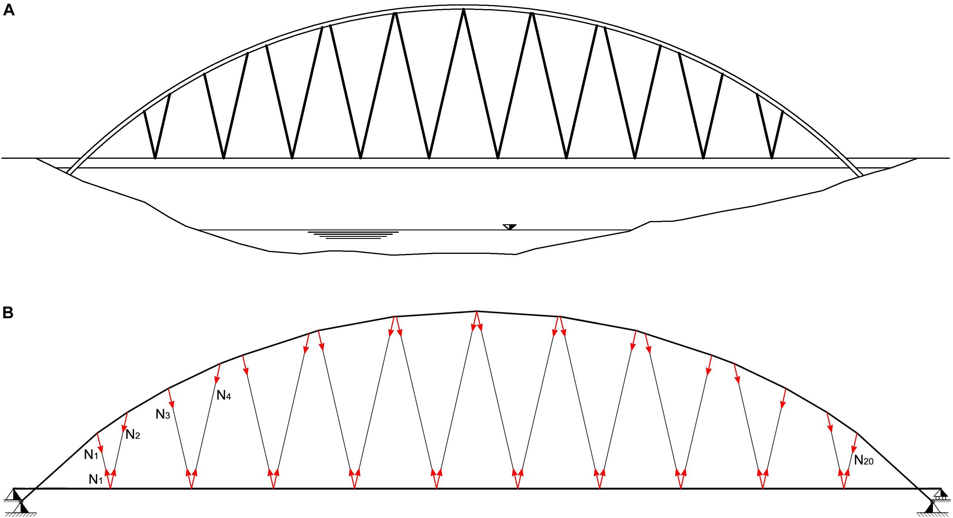
Figure 1. Reference configuration C0 of a Nielsen arch bridge model with n=20: (A) front view; (B) structural model.
We aim at identifying convenient values of the pretension forces to be applied to the stays that lead us to obtain a desired bending moment distribution (BMD) over the deck. A convenient BMD is that corresponding to a deck responding as a continuous beam supported over the hanging points of the stays (continuous-beam deck configuration). One could obtain this TBMD through a material stiffening procedure, by significantly increasing the size of the cross-section of the stays and the arch, and/or using a very stiff material for such members. Let denote a fictitious configuration of the i-th macro-element, which corresponds to assuming the Young modulus of the material 1000 times larger than the real value. We introduce the virtual configuration V0 of the bridge, which is formed by the assembling of , which is a good approximation of the desired continuous-beam deck configuration (Figure 2). The vector Nd collects the cable forces for configuration V0. We refer to such forces as the “optimal pretension forces” in the remainder of the paper.
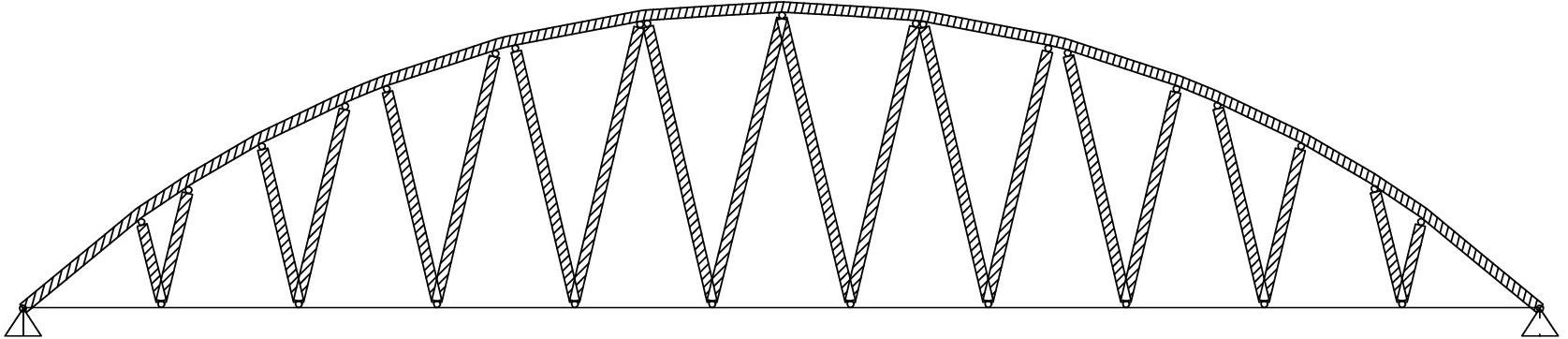
Figure 2. Virtual bridge configuration V0 showing fictitiously stiffened stays and arch.
A geometric-stiffening approach to the TBMD consists of applying a suitable state of self-stress to C0, while leaving material properties and member sizing unchanged (Skelton and de Oliveira, 2010). The state of self-stress to be applied follows from the application of suitable axial forces to the stays, so that the final forces acting in such members will be equal to Nd. Due to the above mentioned static determinacy of E2 (when the forces acting in the stays are known), the action of the forces Nd ensures that the BMD over the deck closely approximates the TBMD.
We determine the optimal pretension forces by solving a set of n elementary elastic problems, each of which corresponds to the application of a unit force in a single stay. Let us introduce the n×n influence matrix A whose entry Aij is equal to the axial force acting in the j-th cable of C0 when the i-th cable is subject to a unit pretension force, and no external loads are applied to the bridge. It is an easy task to verify that it results
Equation (1) rules the cable pretension algorithm adopted in the present study, which returns the desired optimal pretension factors . It is worth observing that the influence matrix A is an intrinsic property of the bridge. As a consequence, the application of Eqn. (1) to different loading conditions is an easy task, once the vectors N0 and Nd have been computed through an elastic analysis of C0 and V0, respectively. The linear nature of Eqn. (1), and the limited number of cables that characterize real-life suspended bridges, allow us to conclude that, in most cases, it possible to solve such an equation with running time less than 1 s.
We have already observed that the deck is a statically determinate structure when the forces in the stays N are known. One can therefore easily obtain the vector M collecting all the deck bending moments at the cables’ hanging points through the following linear equation
where B is a suitable n×n equilibrium matrix. Let us consider now the following quadratic programming problem
where Ny denotes the vector of the yielding forces of the stays. Such a problem searches for the cable forces that minimize the sum of squares of the deck bending moments M. Its solution requires the adoption of iterative solution procedures (refer, e.g., to Gill et al., 1981). Assuming that it results Nd≤Ny, the vector Nd lead us to an approximate solution of problem (3). The accuracy of the approximation scheme based on setting N = Nd is highlighted by the numerical results presented in Section “Numerical Results.” Such results indeed show that the pretension forces obtained through the linear system (1) induce a significant reduction of the bending moments acting on the deck, as compared to the BMD in absence of cable pre-tension. We let Cd denote the configuration of the bridge that features N = Nd.
Finite Element Model
This section presents the numerical implementation of the analytical method given in Section “Computation of Cable Pretension Forces” with reference to a case study of a Nielsen arch bridge featuring a span of 140.8 m and an aerodynamic shape. The deck is suspended to a steel arch by 20 cables, which form ten V-shaped elements made of steel, as it is shown in Figure 1 (refer to Table 1 for the main geometric parameters). The deck rests on a two-cell box girder made of steel, which is locally reinforced to avoid local instability, and has a total width of 8.0 m and height of 1.8 m. The deck houses a 7.5 m wide roadway, two side platforms of 1.50 m each, and two pedestrian walkways of 1.70 m each (Figure 3). The latter are made with a metal grating that rests on cantilevered steel beams. The arch has a tubular section with a diameter of 1.50 m and it is constrained by hinge connections at its ends. Local stiffeners secure the cables (or tie rods) to the arch during the construction phase. The deck can be described as a beam on continuous supports with a pitch of 12.80 m, which is the distance between two consecutive suspension cables.
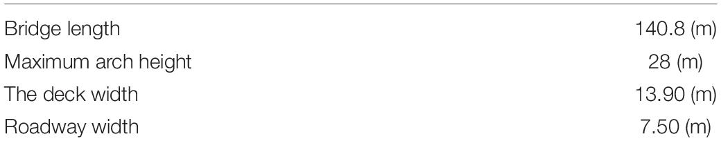
Table 1. Main geometric parameters of the analyzed bridge model.
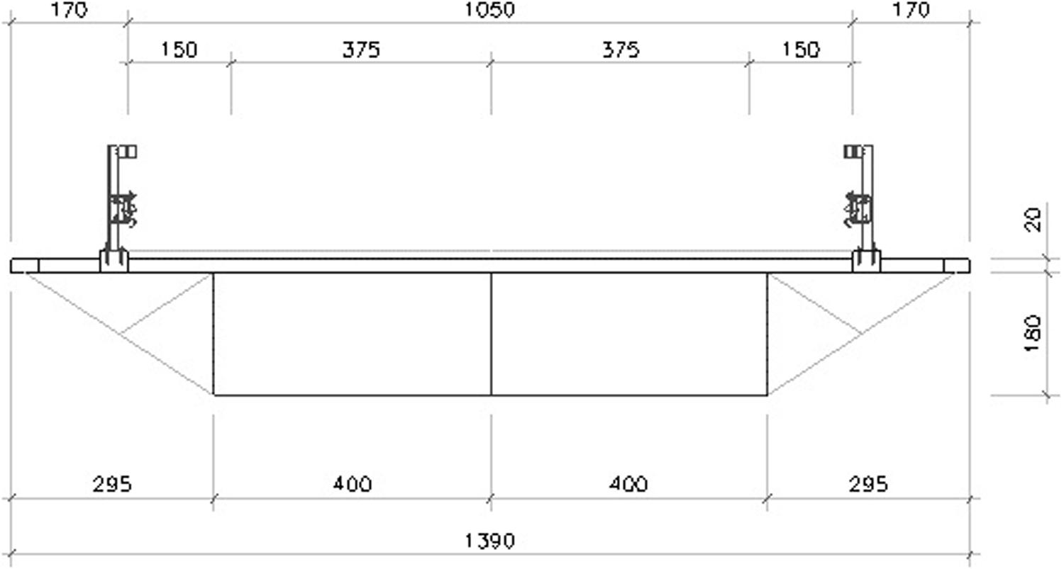
Figure 3. Transverse section of the bridge (unit: cm).
The static indeterminacy of the overall bridge structure is equal to the number of cables + 1 (i.e., 21). We refer the reader to Falanga (2019) for an in-depth description of the bridge model under examination. A two-dimensional finite element model featuring the properties described in Table 2 is employed to predict the response of the bridge under assigned loading conditions. It is worth observing that the adopted cross-section of the arch carries a maximum bending moment of 3,16 × 10⁴ kNm in the fully elastic regime; the cross-section of the deck carries a maximum elastic bending moment of 2,25 × 10⁵ kNm; and the cables can carry a maximum elastic tensile force of Ny = 3,88 × 10³ kN. The influence matrix associated with the present bridge model is given in Table 3, and one observes that such a matrix is dense. A graphical illustration of the effects produced in all cables by the application of a unit pretension of selected cables is given in Figure 4. The results presented in Table 3 highlight that the influence matrix has leading diagonal terms, which implies that problem (1) is well conditioned.
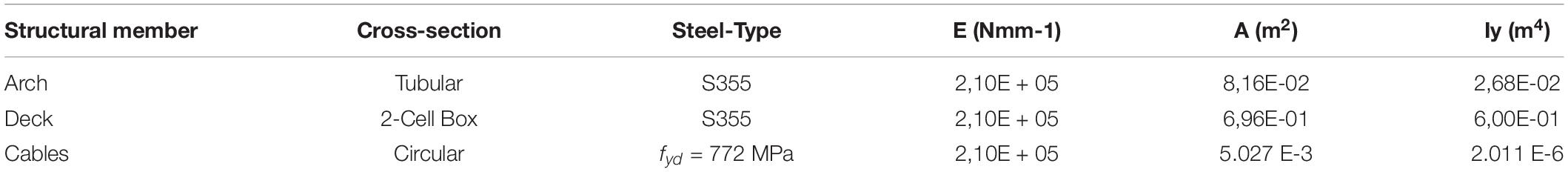
Table 2. Mechanical properties of the employed finite element model of the bridge.
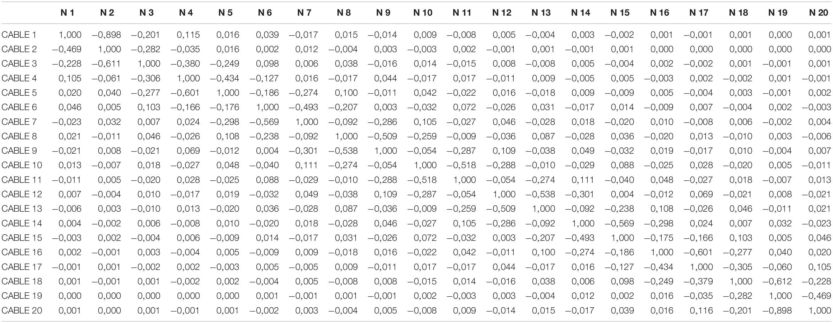
Table 3. Influence matrix of the analyzed finite element model (unit: kN).
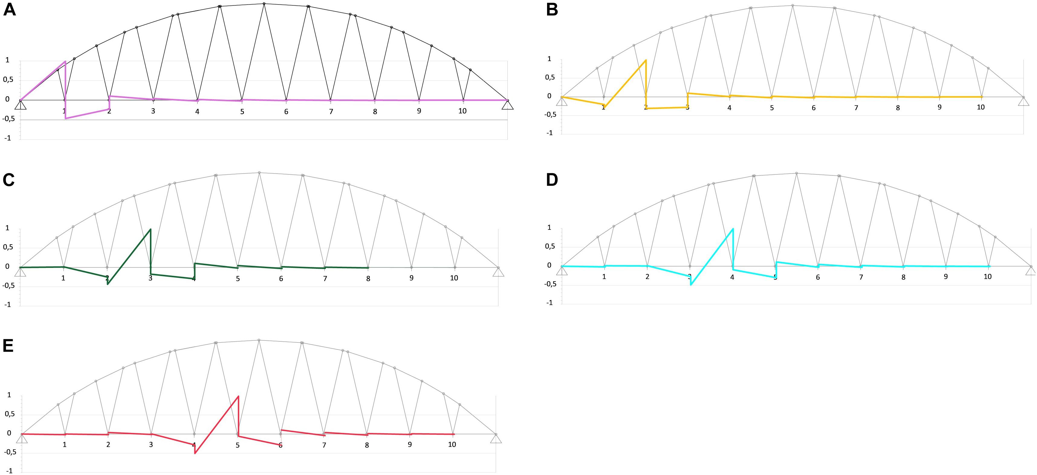
Figure 4. Diagrams of the axial forces acting in all the cables when a selected cable is subject to a unit pre-tension. (A) Effects of a unit pre-tension of cable # 1. (B) Effects of a unit pre-tension of cable # 3. (C) Effects of a unit pre-tension of cable # 5. (D) Effects of a unit pre-tension of cable # 7. (E) Effects of a unit pre-tension of cable # 9.
Numerical Results
The following sections illustrate a collection of numerical results, which examine the effects of different loading conditions on the bridge model described in the previous section. The first example deals with a uniformly distributed load (UDL) that corresponds to the self-weight of the structure (Section “Load Case 1”), while the second and third examples analyze the action of a partially distributed uniform load (PUDL) in proximity to the middle span (Section “Load Case 2”), and over one half of the span of the deck (Section “Load Case 3”), respectively. The 4th loading condition refers to a moving UDL superimposed to permanent loads (Section “Load Case 4”). Such a condition simulates the effects of traffic due to moving cars and lorries, assuming that dynamic amplification effects can be ignored (refer, e.g., to variable Load Model 1 of the European Standards EN 1991-2, 2003).
Load Case 1
The first example refers to the application of UDL with a magnitude of 70 kN/m over the deck (see Figure 5). The procedure described in Section “Computation of Cable Pretension Forces” results in the cable pretension forces given in Figure 6A, and the TBMD illustrated in Figure 6B. The increases of the bending moments carried by the arch, which are produced by the optimal pre-tensioning of the cables (compare Figure 6B with Figure 5B), can be safely supported by the cross-section adopted for this member (cf. Table 2), since the maximum bending moment that the arch can carry in the fully elastic phase is equal to 3,16 × 10⁴ kN m (cf. Section “Finite Element Model”). The maximum force in the stays Nd,max is equal to 1.14 × 10³ kN (cable #6). Such a force is significantly lower than the yielding force Ny = 3,88 × 10³ kN (cf. Section “Finite Element Model”).
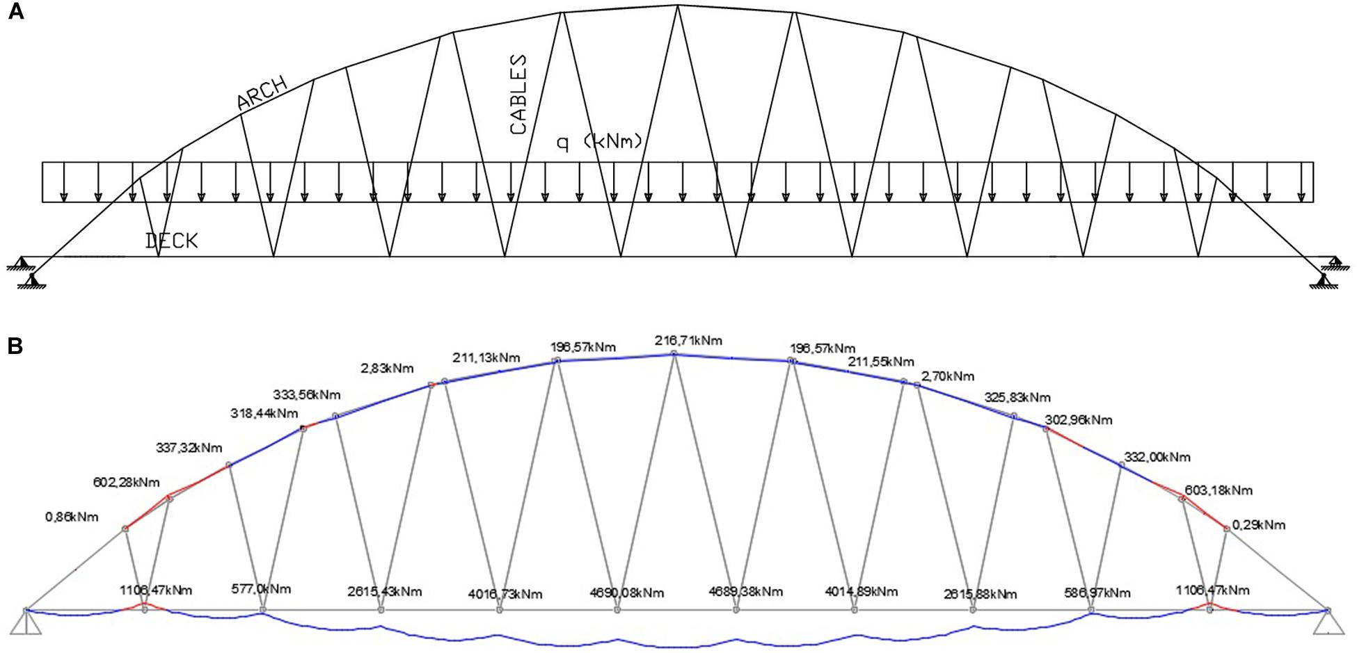
Figure 5. Illustration of load case 1. (A) Load distribution. (B) Bending moment distribution over the deck and the arch in absence of cable pre-tension.
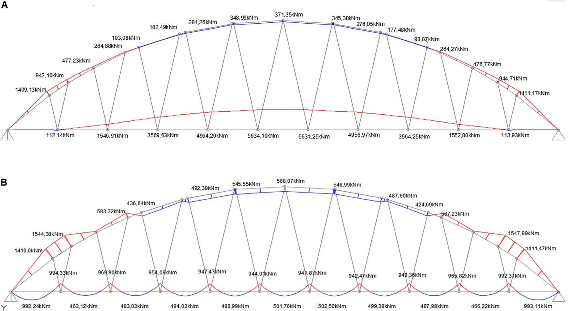
Figure 6. Bending moment distributions for load case 1. (A) BMD produced by the action of the optimal cable pre-tension forces alone. (B) TBMD produced by the combined action of self-weight + optimal cable pre-tension forces.
Load Case 2
Load case 2 is a PUDL of 70 kN/m applied to the three central segments of the deck. The application of an optimization procedure similar to that presented with reference to load case 1 leads to the results illustrated in Figure 7. One observes that the BMD produced by the optimal pre-tension of the cables (Figure 7C) features peak values whose intensity is reduced by approximately 10 times, for both positive and negative values, as compared to the BMD associated with zero pre-tension forces (Figure 7B). Conversely, the bending moments in the arch increase in magnitude under optimal pretension forces, comparing with the case with zero pre-tensions. This is not a concern for the current design strategy, since the final bending moments in the arch are not dramatically high (peaks of the order of 2500 kNm), and can be safely sustained by this member in the elastic regime (maximum elastic bending moment equal to 3,16 × 10⁴ kNm, cf. Section “Finite Element Model”). In the present case, we observe Nd,max = 1.31 × 10³ kN in cable #11.
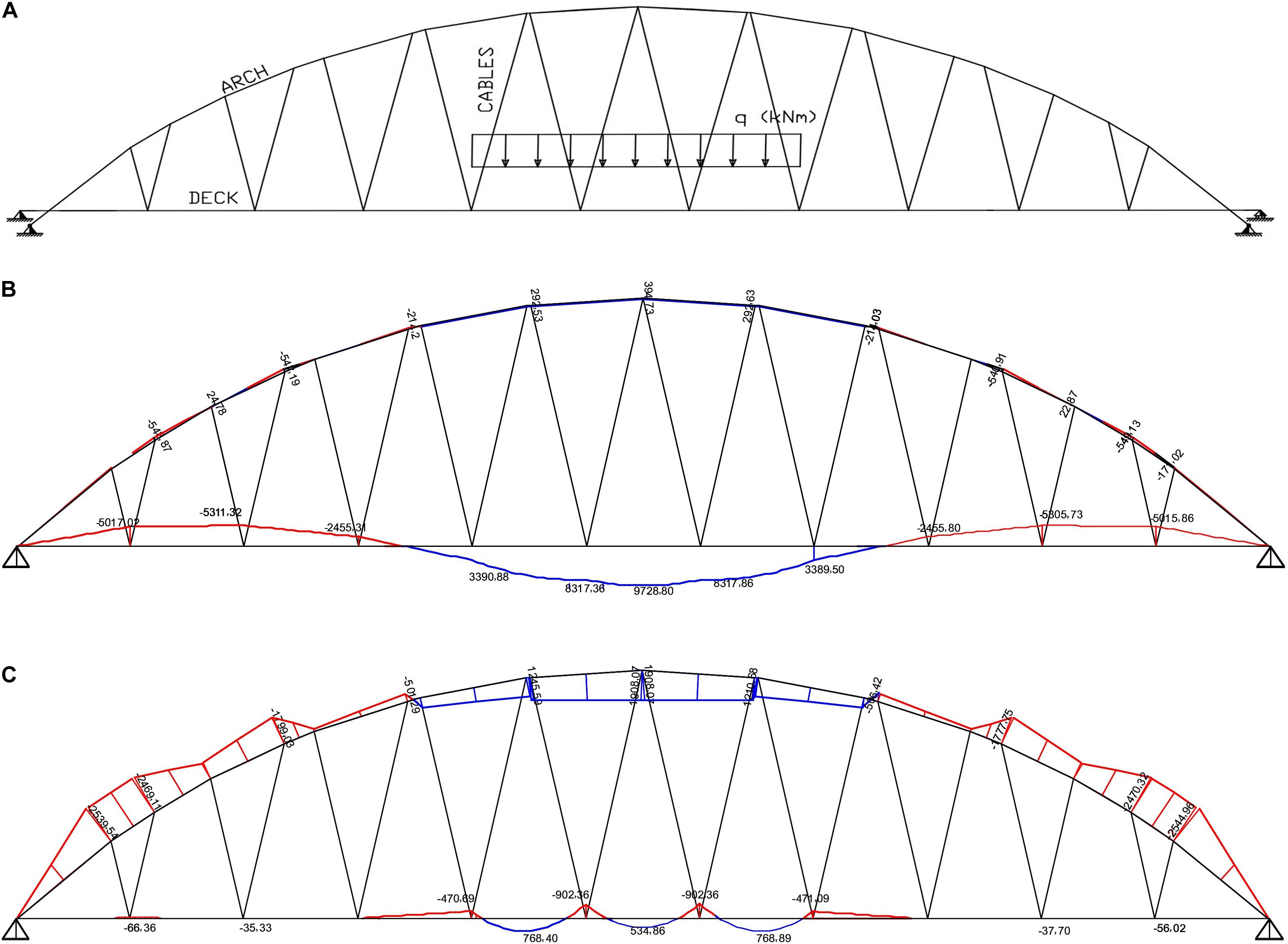
Figure 7. Numerical results for load case 2. (A) Load case 2: action of a PUDL over three central segments of the deck. (B) BMD over the deck and the arch under zero cable pre-tension forces. (C) TBMD produced by the optimal cable pre-tension forces.
Load Case 3
Load case 3 is a PUDL of 70 kN/m applied on one half of the deck. The results of the optimization procedure referred to such a loading condition is illustrated in Figure 8 (Nd,max = 0.93 × 10³ kN in cable #18). The TBMD produced by the optimal pre-tensioning of the cables shows peaks at the hanging points of the cables (Figure 8C), which are about 1/10 of the analogous peaks of the BMD corresponding to zero pre-tension forces (Figure 8B). The bending moment carried out by the arch increases moderately when pre-tension forces are applied.
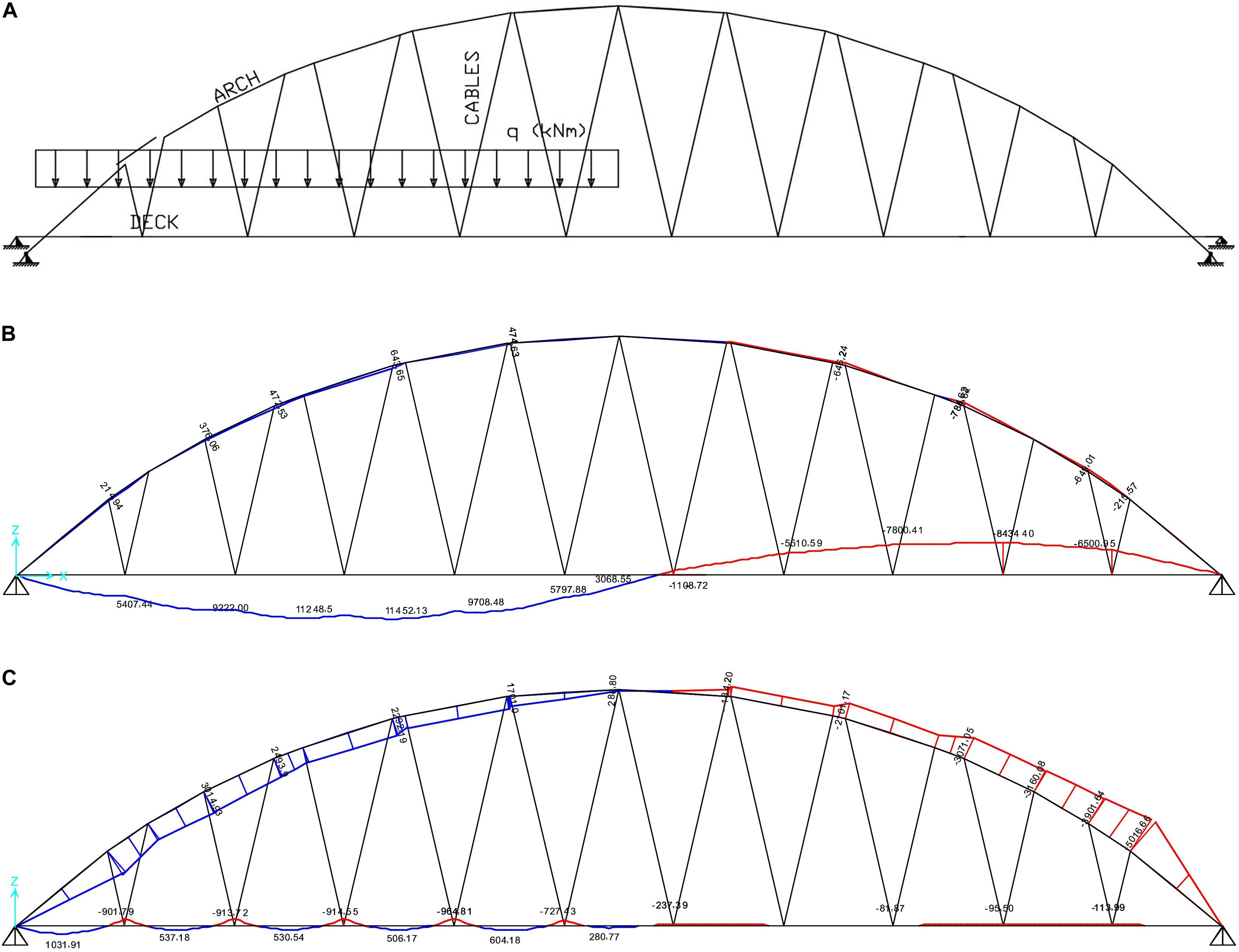
Figure 8. Numerical results for load case 3. (A) Load case 3: action of a PUDL over one half of the deck. (B) BMD over the deck and the arch under zero cable pre-tensioning. (C) TBMD produced by the optimal cable pre-tensioning.
Load Case 4
Load case 4 simulates vertical loads caused by vehicular traffic and lorries through a PUDL qa = 70 kN/m that moves from left to right, and covers the entire span of the bridge. Such a load is superimposed to a UDL qp = 80 kN/m corresponding to the summation of all the permanent loads.
Figure 9 illustrates the TBMDs induced by the optimal pretension forces that are associated with the three different positions of the moving load. Labels 4.1, 4.2, and 4.3 indicate loading scenarios which feature qa distributed over 1/3, 2/3 and the entire span of the bridge, respectively. The TBMD bending moment peaks reduce by approximately 1/10 with respect to the case where no cable pretension is applied (BMD). One again observes that the peaks of the TBMDs exhibit the peaks of the bending moments that are reduced by ≈1/10 with respect to those of the BMD without cable pretensioning, for each examined loading scheme. Table 4 reports the optimal pretension factors corresponding to the TBMDs in Figure 9. We observe values of Nd,max equal to 1.67 × 10³ kN (cable #1), 1.98 × 10³ kN (cable #13) and 1.86 × 10³ kN (cable #18) in the load conditions 4.1, 4.2, and 4.3, respectively.
Figure 9. Numerical results for load case 4. (A): current load distribution; (B): BMD over the deck and the arch under zero cable pre-tensioning; (C) TBMD produced by the optimal cable pre-tension forces.
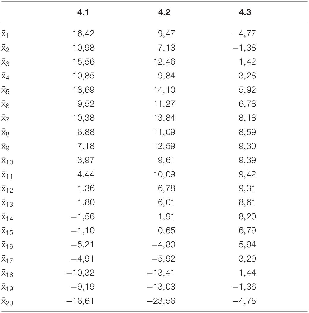
Table 4. Optimal pretension factors corresponding to the TBMDs in Figure 9.
The results in Figure 9 suggest that Eqn. (1) can be usefully employed within a closed loop active control system of the bridge under examination. Let us assume that the road pavement has been equipped with a WIM technology that allows the vehicles to be continuously weighed during traffic flow (refer, e.g., to Jacob and Feypell-de La Beaumelle, 2010 for an overview of available WIM technologies). In addition, let us suppose that all the stays have been equipped with hydraulic actuators, so as to behave as active tendons (Preumont, 2011; Coelho et al., 2015). One could design an active control system that operates according to the following methodology: (i) WIM sensors measure the variations of the moving loads on selected sections of the bridge and send the data to a controller; (ii) the controller solves Eqn. (1), determining the optimal pretension forces to be applied to the stays, and sends this information to the hydraulics actuators mounted on the stays; (iii) the actuators apply the optimal pretension forces to all the stays, determining the achievement of the TBMD over the deck. Additional mechanical and optical sensors measuring the forces in the stays and the deflections of the deck should also be integrated to ensure the system operates within required limit states. Assuming that dynamic effects as well as errors between the model and the real physical structure are compensated by other means, the proposed control strategy could be employed to mitigate the effect of loading on arch bridges with suspended deck. Time delay due to data transmission from the WIM sensors to the controller and from the controller to the actuators could be reduced by predicting the load distribution from previous measurements through vehicle speed estimation methods (Lu et al., 2020).
Conclusion
This paper has developed a linear elastic analysis for suspended deck arch bridges, which generalizes the studies presented in Fabbrocino et al. (2017) and Mascolo and Modano (2020) for beam bridges. By employing an engineering approximation to the mathematical optimization problem of the cable-pretension forces, an IMM has been formulated to determine a TBMD along the deck, which mimics a continuous-beam-type of response. Since the IMM is a linear system of equations with a reduced number of unknowns with respect to the full optimization problem, it could be suitable to be employed as part of a strategy for real-time control. Assuming a linear behavior, the coefficient matrix of such a system is an intrinsic property of the bridge, and therefore it does not need to be modified when dealing with moving loads.
The results given in Section “Numerical Results” allow us to conclude that the cable pre-tensioning procedure presented in this study can be usefully employed within active control systems of cable-stayed bridges subject to moving vertical loads, when dynamic amplification effects can be neglected. It is aimed at controlling the response of the structure under ordinary service conditions, leading to the following key results: (a) to effectively “correct” the configuration of the bridge after completion of the construction process (Van Bogaert and De Backer, 2019); (b) to increase the load-bearing capacity when significant variations in mobile loads are to be expected, new vehicles are put into circulation or new technical regulations are enforced; (c) to strengthen new and existing structures by suitably reducing the peaks of the BMDs through an optimized cable pre-tensioning. We address such applications of the current research to future work, through analytical and experimental studies (Reksowardojo et al., 2018, 2019; Senatore et al., 2018a, b, 2019). Additional future research lines may include an iterative, incremental formulation of the optimization procedure presented in Section “Computation of Cable Pretension Forces,” to be aimed at handling dynamic effects (such as wind- or accidental-load-induced vibrations); time-dependent phenomena (viscous response of the materials of the arch and the deck, relaxation of the pre-stress of the tendons, etc.); and/or geometric non-linearities. Finally, we plan to compare different engineering strategies for the choice of the TBMD in future studies dealing with different typologies of suspended beam and arch bridges.
Data Availability Statement
The original contributions presented in the study are included in the article/supplementary material, further inquiries can be directed to the corresponding author.
Author Contributions
MM and FF led the mechanical modeling phases of the present study. MM designed and carried out the numerical simulations. AM collaborated to development of the numerical results. FS, RL, and FF supervised all the phases of the project. All authors contributed to the article and approved the submitted version.
Funding
AM and FF acknowledge financial support from the MIUR under the PRIN 2017 National Grant “Multiscale Innovative Materials and Structures” (grant number 2017J4EAYB).
Conflict of Interest
The authors declare that the research was conducted in the absence of any commercial or financial relationships that could be construed as a potential conflict of interest.
References
Casas, J. R. (2015). The bridges of the future or the future of bridges? Front. Built Environ. 1:3. doi: 10.3389/fbuil.2015.00003
Chen, D. W., Au, F. T. K., Tham, L. G., and Lee, P. K. K. (2000). Determination of initial cable forces in prestressed concrete cable-stayed bridges for given design deck profiles using the force equilibrium method. Comput. Struct. 74, 1–9. doi: 10.1016/S0045-7949(98)00315-0
Coelho, H., Resende, A., Carvalho, D., and Soares, I. (2015). “High productivity in bridge construction,” in Proceedings of the OPS effect - Multi-Span Large Bridges, eds P. Pacheco and F. Magalhles (London: Taylor & Francis Group).
EN 1991-2 (2003). Eurocode 1: Actions on structures - Part 2: Traffic loads on bridges. Brussels: European Union.
Fabbrocino, F., Modano, M., Farina, I., Carpentieri, G., and Fraternali, F. (2017). Optimal prestress design of composite cable-stayed bridges. Composite Struct. 169, 167–172. doi: 10.1016/j.compstruct.2016.09.008
Falanga, V. (2019). Procedura di ottimizzazione per ponti ad arco tipo Nielsen per la mitigazione delle sollecitazioni dovute alle modalità di varo. MSc Thesis, University of Naples, Federico II.
Freire, A. M. S., Negrão, J. H. J. O., and Lopes, A. V. (2006). Geometrical nonlinearities on static analysis of highly flexible steel cable-stayed bridge. Comput. Struct. 84, 2128–2140. doi: 10.1016/j.compstruc.2006.08.047
Gill, P. E., Murray, W., and Wright, M. H. (1981). Practical Optimization. Cambridge, MA: Academic Press.
Jacob, B., and Feypell-de La Beaumelle, V. (2010). Improving truck safety: Potential of weigh-in-motion technology. IATSS 34, 9–15. doi: 10.1016/j.iatssr.2010.06.003
Lazar, B. E., Troitsky, M. S., and Douglass, M. M. (1972). Load balancing analysis of cable-stayed bridges. J. Struct. Divis. 98, 1725–1740.
Lee, T. Y., Kim, Y. H., and Kang, S. W. (2008). Optimization of tensioning strategy for asymmetric cable-stayed bridge and its effect on construction process. J. Struct. Multidiscipl. Optim. 35, 623–629. doi: 10.1007/s00158-007-0172-9
Lonetti, P., and Pascuzzo, A. (2014). Optimum design analysis of hybrid cable-stayed suspension bridges. Adv. Eng. Softw. 73, 53–66. doi: 10.1016/j.advengsoft.2014.03.004
Lu, S., Wang, Y., and Song, H. (2020). A high accurate vehicle speed estimation method. Soft Comput. 24, 1283–1291. doi: 10.1007/s00500-019-03965-w
Mascolo, I., and Modano, M. (2020). Optimisation of suspended-deck bridge design: a case study. Aust. J. Struct. Eng. 2020:1778433. doi: 10.1080/13287982.2020.1778433
Reksowardojo, A. P., Senatore, G., and Smith, I. F. C. (2018). “Actuator layout optimization for adaptive structures performing large shape changes,” in Advanced Computing Strategies for Engineering. EG-ICE 2018. Lecture Notes in Computer Science, 10864, Lausanne, eds I. F. C. Smith and B. Domer (Cham: Springer), 111–129. doi: 10.1007/978-3-319-91638-5_6
Reksowardojo, A. P., Senatore, G., and Smith, I. F. C. (2019). Experimental testing of a small-scale truss beam that adapts to loads through large shape changes. Front. Built Environ. 5:93. doi: 10.3389/fbuil.2019.00093
Senatore, G., Duffour, P., and Winslow, P. (2018a). Energy and cost analysis of adaptive structures: case studies. J. Struct. Eng. 144:04018107. doi: 10.1061/(asce)st.1943-541x.0002075
Senatore, G., Duffour, P., Winslow, P., and Wise, C. (2018b). Shape control and whole-life energy assessment of an “Infinitely Stiff” prototype adaptive structure. Smart Mater. Struct. 27:015022. doi: 10.1088/1361-665x/aa8cb8
Senatore, G., Duffour, P., and Winslow, P. (2019). Synthesis of minimum energy adaptive structures. Struct. Multidiscipl. Optim. 60, 849–877. doi: 10.1007/s00158-019-02224-8
Simões, L. M. C., and Negrão, J. H. J. O. (1995). “Optimization of Cable-Stayed Bridges Subjected to Dynamic Loading,” in Proceedings of Conference: The First World Congress on Structural and Multidisciplinary Optimization, Goslar, 1–7.
Song, C., Xiao, R., and Sun, B. (2018). Optimization of cable pre-tension forces in long-span cable stayed bridge considering the counterweight. Eng. Struct. 172, 919–928. doi: 10.1016/j.engstruct.2018.06.061
Sung, Y. C., Chang, D. W., and Teo, E. H. (2006). Optimum post-tensioning cable forces of Mau-Lo His cable-stayed bridge. J. Eng. Struct. 28, 1407–1417. doi: 10.1016/j.engstruct.2006.01.009
Van Bogaert, P., and De Backer, H. (2019). Continuous prestress in launched extradosed bridges. Front. Built Environ. 5:81. doi: 10.3389/fbuil.2019.00081
Wang, P. H., Tseng, T. C., and Yang, C. G. (1993). Initial shape of cable-stayed bridges. Comput. Struct. 46, 1095–1106. doi: 10.1016/0045-7949(93)90095-u
Wang, P. H., and Yang, C. G. (1996). Parametric studies on cable-stayed bridges. Comput. Struct. 60, 243–260. doi: 10.1016/0045-7949(95)00382-7
Wang, Y. C., Vlahinos, A. S., and Shu, H. S. (1997). “Optimization of cable preloading on cable-stayed bridges. In Proc. SPIE. Smart Structures and Materials 1997,” in Proceedings of the Smart Systems for Bridges, Structures, and Highways, Vol 3043, San Diego, CA, 248–259. doi: 10.1117/12.274650
Keywords: arch bridges, pretension, target bending moment distribution, influence matrix, Nielsen bridge
Citation: Modano M, Majumder A, Santos F, Luciano R and Fraternali F (2020) Fast and Optimized Calculation of the Cable Pretension Forces in Arch Bridges With Suspended Deck. Front. Built Environ. 6:114. doi: 10.3389/fbuil.2020.00114
Received: 24 March 2020; Accepted: 22 June 2020;
Published: 16 July 2020.
Edited by:
Gennaro Senatore, École Polytechnique Fédérale de Lausanne, SwitzerlandReviewed by:
Francesco Tornabene, University of Salento, ItalyNizar Bel Hadj Ali, École Nationale d’Ingénieurs de Gabès, Tunisia
Philippe Van Bogaert, Ghent University, Belgium
Copyright © 2020 Modano, Majumder, Santos, Luciano and Fraternali. This is an open-access article distributed under the terms of the Creative Commons Attribution License (CC BY). The use, distribution or reproduction in other forums is permitted, provided the original author(s) and the copyright owner(s) are credited and that the original publication in this journal is cited, in accordance with accepted academic practice. No use, distribution or reproduction is permitted which does not comply with these terms.
*Correspondence: Fernando Fraternali, Zi5mcmF0ZXJuYWxpQHVuaXNhLml0