 Qinyu Wang
 Gennaro Senatore
 Kaspar Jansen
 Arjan Habraken
 Patrick Teuffel
- 1Department of Built Environment, Chair of Innovative Structural Design (ISD), Eindhoven University of Technology, Eindhoven, Netherlands
- 2Applied Computing and Mechanics Laboratory, School of Architecture, Department of Civil and Environmental Engineering, Swiss Federal Institute of Technology (EPFL), Lausanne, Switzerland
- 3Department of Industrial Design Engineering, Delft University of Technology, Delft, Netherlands
This paper introduces a new semi-active strategy for vibration control of truss and frame structures equipped with variable stiffness and damping joints which consist of a shape memory polymer (SMP) core reinforced by an SMP-aramid composite skin. When the joints are actuated to the transition temperature through thermal actuation, the SMP core transitions from a glassy to a rubbery state through a viscoelastic region, which causes a stiffness reduction and an increase of damping. The mechanic behavior of the joint can be thought of as transitioning from a moment to a pin connection. This way, it is possible to cause a shift of the structure natural frequencies and to increase damping, which is employed to obtain a significant reduction of the dynamic response. This paper comprises two parts: (1) characterization of a variable stiffness and damping material model through experimental testing; (2) numerical simulations of a truss bridge and a four-story frame, which are equipped with variable stiffness and damping joints. The truss bridge (case A) is subjected to a resonance and a moving load while the four-story frame (case B) is subjected to El Centro earthquake loading. For case A under resonance loading, the dynamic response can be reduced exclusively through a frequency shift and ignoring viscoelastic effects. For case A under moving load and case B under earthquake loading, vibration suppression is mostly caused by the increase of damping due to viscoelastic effects. Control time delays due to joint heating have been included in the analysis. When the joints are actuated to the transition range 55°C–65°C, which is specific to the SMP adopted in this study, the acceleration peak amplitude reduces by up to 95% and 87%, for case A and case B, respectively. For both cases, damping increases by up to 2.2% from undamped conditions (25°C). This work has shown that the adoption of variable stiffness and damping structural joints has great potential to enable a new and effective semi-active control strategy to significantly reduce the structure response under a wide range of dynamic loading conditions.
Introduction
Adaptive Structures
Adaptive structures are equipped with actuators, sensors, and controllers to maintain optimal performance under changing loading conditions. Through mechanical actuation the state of the structure (stress and deformation) can be modified to counteract actively the effect of loading. Structural control strategies have been categorized in four types: active, semi-active, passive, and hybrid (Soong and Spencer, 2000; Preumont and Seto, 2008). Numerical and experimental studies on active bracing for buildings and active tendons for bridges have shown that active control systems can be effectively employed for vibration suppression under strong loading such as high wind or earthquakes (Soong, 1988; Reinhorn et al., 1993; Xu et al., 2003; Mirfakhraei et al., 2019).
Benchmark control problem studies for seismic (Spencer et al., 1998; Ohtori et al., 2004) and wind excited (Yang et al., 2004) buildings have shown that through active control, the structure response (e.g., displacement, acceleration, and inter-story drift) can be reduced significantly more than through passive control. Although active controlled systems are more effective to suppress vibrations than passive ones, they generally require high power density supply and they might require a large energy consumption during service. In addition, due to latency and model inaccuracy, the control forces might cause instability of the structure-control system (Kınay and Turan, 2012; Wang et al., 2017). Semi-active control systems, such as magnetorheological (MR) dampers, require less energy compared to active systems. In addition, they are as reliable as passive devices while maintaining some of the versatility and adaptability of fully active systems (Dyke et al., 1996; Symans and Constantinou, 1999; Yang et al., 2002; Zhao et al., 2019). Generally, closed-loop semi-active control systems perform better than passive ones. Although passive control systems such as base isolation (Huang et al., 2014), viscoelastic and elastoplastic dampers (Kasai et al., 1998) require no control power, they have limited capabilities compared to active and semi-active systems. Hybrid control systems (for example hybrid mass dampers) might combine passive, semi-active and active control strategies and devices (Spencer and Sain, 1997; Kınay and Turan, 2012). For example, a hybrid vibration control system which combines a base isolator and an active tuned mass damper was investigated in Djedoui et al. (2017). This hybrid system was able to reduce by more than 70% the base isolator displacement while keeping the base acceleration within an acceptable range, which was more effective than the response reduction obtained through a passive control system made of a base isolator and a passive tuned mass damper (Djedoui et al., 2017). However, hybrid control systems are generally complex and might involve significant maintenance costs (Gkatzogias and Kappos, 2016).
The ability to counteract the effect of loading actively through control of internal forces and the external geometry, has been employed in integrated structure-control design to produce efficient configurations with a significantly better material utilization (Teuffel, 2004) and a lower whole-life energy (Senatore et al., 2019; Senatore and Reksowardojo, 2020; Wang and Senatore, 2020) than conventional passive structures. The whole-life energy comprises the energy embodied in the material and the operational energy for control. Extensive numerical (Senatore et al., 2018a, b) and experimental studies (Senatore et al., 2018c) have shown that minimum energy adaptive structures have a lower environmental impact as the total energy requirement can be reduced by up to 70% compared to weight-optimized passive structures. Structural adaptation is particularly beneficial for stiffness governed design problems such as slender high-rise structures, long-span bridges and self-supporting roof systems. When the structure is designed to counteract the effect of loading through controlled large shape changes, further material and embodied energy savings are obtained compared to adaptive structures limited to small shape changes as well as to passive structures (Reksowardojo et al., 2019, 2020). This way, the structure is controlled into optimal shapes as the external load changes so that the stress is significantly homogenized, and the design is not governed by strong loading events which occur rarely. Shape control has also been employed to reduce the dynamic response through shifting the structure natural frequencies (Bel Hadj Ali and Smith, 2010; dos Santos et al., 2015; dos Santos and Cismaşiu, 2017) and for the control of direct daylight in buildings through adaptive façade systems (Lienhard et al., 2011; Lignarolo et al., 2011).
One of the most important aspects in the design of adaptive structures is to consider the mechanical behavior of the joints. Since active control requires some degree of geometry reconfiguration, the joints should be designed to be flexible during control in order to prevent stress build-up and to reduce control energy requirements. Joint mechanisms based on pin-joints or linkages could be employed, however, these systems often add a substantial weight penalty and they are generally complex devices which require maintenance (Campanile, 2005). To address this challenge, a new type of variable stiffness and damping joint has been proposed in previous work (Senatore et al., 2017). The joint has been modeled to have two states: in the “locked” state, it behaves as a moment connection and in the “released” state, it behaves as a pin connection. A numerical study on a Warren truss has shown that by selectively switching the joint states, the structure natural frequencies could be controlled to shift significantly (Wang et al., 2018). In practice, transition from a moment to a pin connection has been realized through control of the joint stiffness (Wang et al., 2020). The joint is made of a polyurethane based shape memory polymer (SMP) core that is reinforced by an SMP-aramid skin. Stiffness variation has been achieved through resistive heating of the joint core material. When the SMP core is heated up to the transition temperature (65°C), a change from a glassy to a rubbery state occurs, which causes a significant stiffness reduction of the joint and a parallel damping increase due to viscoelastic effects. The material behavior has been fully characterized through Dynamic Mechanical Analysis (Wang et al., 2020).
Most semi-active control strategies aim to mitigate the structure response by appropriate adjustments of the magnitude of control forces that develop through motion (e.g., electrorheological dampers, magnetorheological dampers, fluid viscous dampers). Semi-active strategies based on stiffness and damping control instead, aim to mitigate the structure response by tuning its dynamics characteristics. Existing semi-active stiffness and damping control devices comprise several parts and require complex joint detailing to be installed (Kobori et al., 1993; Sarlis et al., 2013; Shu et al., 2017). The ability to tune stiffness and damping of the joint itself, as formulated in this work, allows for a new type of semi-active stiffness and damping control device. In this case the device is completely integrated because it is part of the structure i.e., the joint is the semi-active device. Numerical simulations on a planar frame equipped with two variable stiffness and damping joints have shown that it is possible to significantly reduce the structure response under resonance loading solely through thermal actuation of the joints. The state change of the joints caused up to 8.72% shift of the first natural frequency and an increase of damping up to 1.2% from undamped conditions (25°C) due to viscoelastic effects (Wang et al., 2020).
Smart Materials for Structural Control
Smart materials such as magnetorheological elastomers, shape memory alloys and polymers have been employed for shock isolation (Ledezma-Ramirez et al., 2011), vibration suppression (Bonello et al., 2005) and shape control applications (Kuder et al., 2013). Shape memory alloy (SMA) linear actuators were applied in shape control of a tensegrity tower to mitigate the structure dynamic response (dos Santos et al., 2015). Magnetorheological elastomer elements have been used as tunable springs to design vibration isolators with tunable stiffness and damping (Du et al., 2011; Liao et al., 2012). Shape memory polymers (SMPs) can move from a deformed shape to an undeformed stress-free shape through thermal, electric and magnetic actuation (Leng et al., 2011; Meng and Li, 2013). SMPs feature large stiffness variation (up to 1,000 times) between a glassy and a rubbery state (Liu et al., 2006; Hu et al., 2017b). Below the transition temperature Tg, the polymer is stiff with a modulus of approximately 1 GPa whereas above Tg, the polymer has a rubbery elastic behavior with a modulus which is approximately two decades (i.e., order of magnitude) lower. SMPs have received attention for application as actuators and smart textiles in deployable and morphing structures (Liu et al., 2011). For example, SMA stripes have been embedded in a SMP matrix for a wind-responsive façade system (Lignarolo et al., 2011). A fiber reinforced SMP hinge has been tested to control the orientation of a solar array prototype in order to maximize solar gain (Lan et al., 2009). It was possible to change the orientation of the solar array by 90° in 80 s. However, application of SMPs in load-bearing structures has been limited due to low mechanical strength. The addition of continuous fibers (for example carbon, glass, and aramid fibers) significantly increases mechanical strength in the fiber direction while keeping the shape memory effect in the transverse direction (Gall et al., 2000; Lan et al., 2009). Generally, shape memory polymer composites (SMPC) are more suitable for application in load-bearing structures (Liu et al., 2011; Hu et al., 2017a).
Outline
Own previous work (Wang et al., 2020) focused on design and characterization of variable stiffness and damping structural joints to be employed as semi-active control devices. This work builds on and generalizes the conclusions reached in Wang et al. (2020) by evaluating the capability of this new semi-active stiffness and damping control device through simulations on more complex structural configurations and loading scenarios. This paper is arranged as follows. Section “Variable Stiffness and Damping Joint” describes the main features of the variable stiffness and damping joint material including characterization through Dynamic Mechanical Analysis. Section “Thermal Actuation” describes numerical simulations of a truss bridge subjected to a resonance and a moving load. Section “Case Study B: Four-Story Frame” describes numerical simulations of a four-story frame subjected to earthquake loading. Both structures are equipped with variable stiffness and damping joints. Joint stiffness and damping control are employed as a strategy to reduce the structure dynamic response through a shift of the natural frequencies as well as an increase of damping due to viscoelastic effects. Section “Discussion” and “Conclusion” conclude this paper.
Variable Stiffness and Damping Joint
The variable stiffness and damping joints considered in this study consists of an SMP core and an SMP-aramid composite skin which acts as a reinforcement (see section “SMP-aramid Skin: Isotropic Elastic Material Model”). Figure 1 shows an example of such joint. The joints were manufactured to be integrated in a 650 mm × 650 mm × 1325 mm three-story frame prototype which is shown in Figure 1A for illustration purposes. Figure 1B shows an example of a joint core. The core is fabricated through fused deposition modeling (FDM). The filament used for 3D printing is obtained from a polyurethane-based SMP (MM5520) which is made by SMP Technologies Inc. MM5520 is a pellet type SMP with a nominal transition temperature of 55°C (as reported by the manufacturer). A 1 mm diameter resistive heating wire is passed through the joint core through a series of holes which have been made through selective deposition. Figure 1C shows the heating wire weave pattern from the back side of the joint core. Figure 1D shows a joint core connected to four aluminum tubes using structural glue (Pattex 100%). Figure 1E shows the assembly (joint + elements) after the reinforcement skin is applied (Wang et al., 2020).
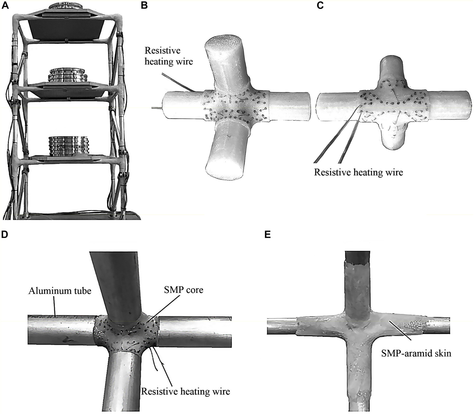
Figure 1. (A) Integration of variable stiffness and damping joints into a 3-story prototype frame; (B,C) SMP core with heating wire; (D) joint core connected to four aluminum tubes; (E) SMP-aramid reinforcement skin (Wang et al., 2020).
Material Characterization
Polymers are materials whose stiffness depends on temperature as well as time (creep) and loading frequency. The standard procedure to characterize viscoelastic behavior is to use a setup in which loading frequency and temperature are varied systematically (Menard, 2008). In previous work (Wang et al., 2020), the thermomechanical properties of a 3D printed SMP strip have been fully characterized through Dynamic Mechanical Analysis (DMA) using a Q800 tester. Figure 2A shows the plots of storage modulus E′, loss modulus E″ and tan δ as functions of the temperature at 1 Hz. The storage modulus E characterizes the elastic part of the material behavior in which strain and stress are in phase as for any other elastic material.
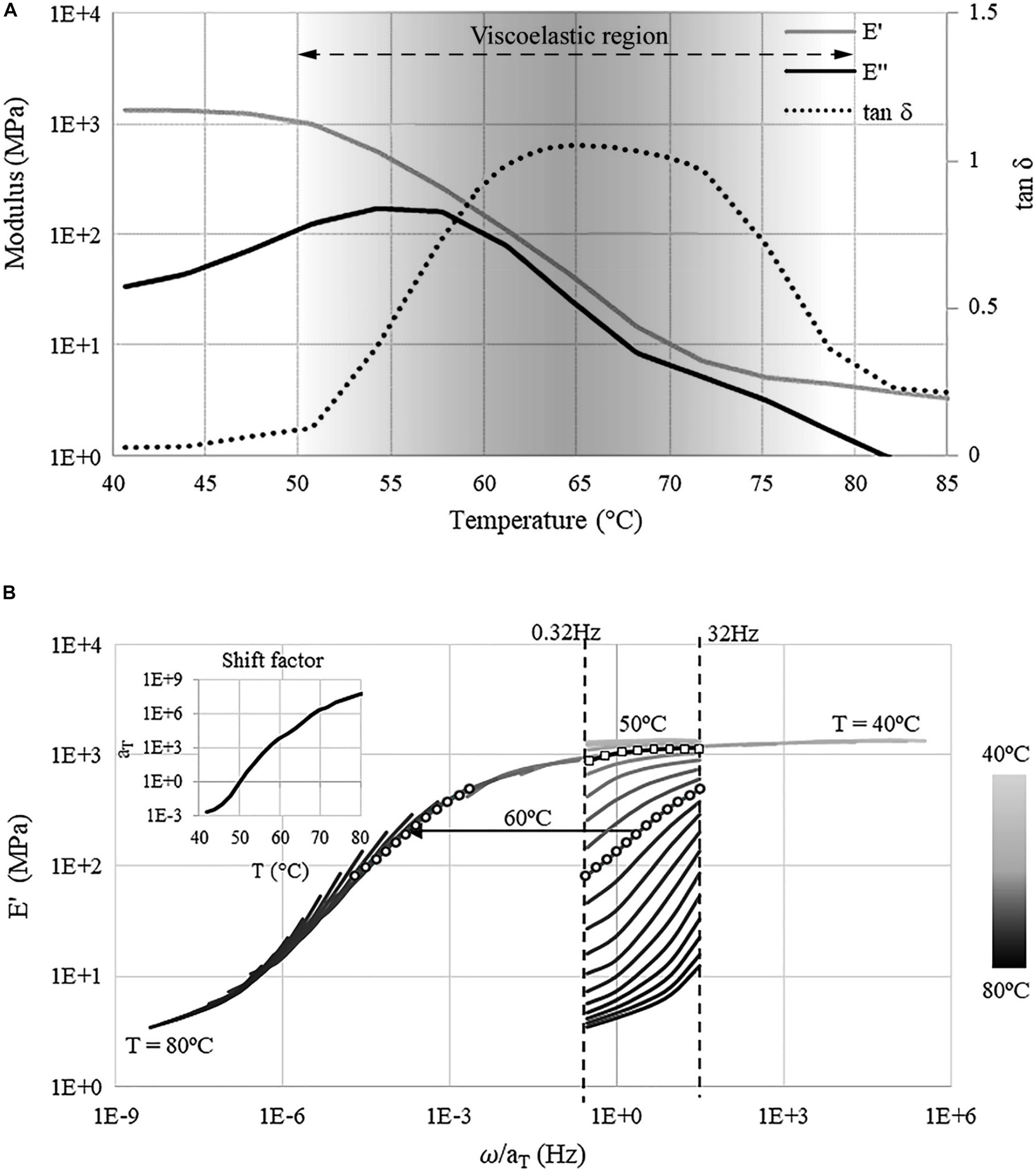
Figure 2. (A) Storage E′, loss E″ modulus, and tan δ vs. temperature at 1 Hz; (B) master and shift factor curves (). Both (A,B) have been obtained through experimental testing (Wang et al., 2020).
When the material enters the viscoelastic region (opaque region in Figure 2A), caused by an increase of temperature, strain and stress are out of phase, which is indicated by the loss modulus E″. The ratio tan δ = E″/E′ is a measure of damping (Menard, 2008; ISO-6721-1, 2011). Through DMA testing, it was found that the transition temperature is 65°C (Wang et al., 2020). During glass transition (40°C–65°C), the storage modulus drops from 1,340 to 37 MPa while damping increases significantly (approximately by a factor of 60). However, as the temperature is increased above the transition value, damping decreases because the material enters the rubbery state which has an elastic behavior.
Time-temperature superposition principle is employed in order to map experimental data obtained at different temperatures and frequencies on a single master curve (Ferry, 1980), which is shown in Figure 2B. Figure 2B also shows the plot of the shift factor curve which relates the change of stress relaxation rate with temperature. The shift factor curve is used to extrapolate to frequencies other than those tested experimentally in order to characterize the viscoelastic behavior in the entire temperature-frequency domain, i.e., to obtain the master curve. The dashed lines in Figure 2B are the storage modulus curves measured in the frequency range 0.32–32 Hz and temperature range 40°C–85°C. The shift factor curve has been approximated by fitting the Williams–Landel–Ferry (WLF) function to the measured data:
where aT is the shift factor. The constants C1 and C2, which have been calculated through fitting, are 14.6 and 24.2, respectively. At the reference temperature Tref = 50°C the shift factor is set to 1. The storage modulus curve in this case is indicated by square markers. The moduli at a temperature and at a frequency that have not been tested through DMA, are obtained by shifting along the frequency axis using the shift factor curve. For example, at 60°C the shift factor aT is approximately 104 which means that stress relaxation is faster by a factor of 104. Consequently, the storage modulus curve at 60°C, which is indicated by circle markers, shifts by a factor of 104 to the left to form the master curve. For a more detailed description of the material model the reader is referred to (Wang et al., 2020).
In addition to the viscoelastic material model, a simpler thermo-elastic model is considered in which frequency dependent effects are neglected and thus the modulus only changes with temperature. For this temperature-only dependent elastic model, the storage modulus curve measured at 1 Hz (Figure 2) is adopted. This way, stiffness variation through temperature is decoupled from damping variation due to viscoelasticity. This simplified material model will be employed for modal analysis as well as transient analysis through mode superposition for the truss bridge (case A) under resonance loading. For the configurations under moving (case A) and earthquake loading (multi-story frame, case B), full transient analysis will be carried out using both thermo-elastic and viscoelastic material model in order to evaluate the combined effect of frequency shift and damping variation on the structure response.
SMP-aramid Skin: Isotropic Elastic Material Model
To reduce potentially excessive deformations of the joint core when it is thermally actuated in the transition range, a reinforcement skin is applied. This skin consists of a stack of woven aramid fabric layers which are impregnated with SMP material to form a stiff and thin composite. The individual fabric layers have fibers oriented at 0° and 90° which feature an anisotropic behavior to loading. Generally, the joints have a complex geometry to connect multiple elements and hence they are likely to be subjected to bending and torsion. For this reason, the reinforcement skin should behave as an isotropic material. Therefore, two additional fabric layers with a 45° orientation have been added, which has resulted in a quasi-isotropic skin with a modulus of approximately 8,320 MPa and a thickness of 1.72 mm (Wang et al., 2020). Thicker skins may be needed to prevent excessive deformation of the joint if high loads are applied, in which case additional 0° and 45° layers might be added. The reader is referred to (Wang et al., 2020) for more information regarding the reinforcement skin design and related experimental testing.
Semi-Active Control Strategy
Feedforward Control
It is clear from material characterization (section “Material Characterization”) that the damping ratio increase caused by viscoelastic effects is the highest when the joint core is thermally actuated in the transition range. It will be shown through full transient analysis (sections “Thermal Actuation” and “Case Study B: Four-Story Frame”) that mitigation of the structure response under dynamic excitation is mostly caused by the increase of damping of the joints. Under excitations that have several high-energy frequency components (e.g., earthquake loading), generally the effect of damping is dominant even when, due to the structure frequency shift that is caused by joint stiffness reduction, a temporary resonance condition arises. For this reason, a simple feedforward control scheme is proposed to mitigate the structure response through thermal actuation of the joints.
Assume a generic multi-story building which is equipped with variable stiffness and damping joints. Accelerometers are installed at each floor. Thermocouples are embedded during fabrication in the core of each joint to monitor the temperature. Figure 3A shows an example of a seismic excitation (in this case El Centro earthquake loading). Figure 3B shows the non-controlled as well as controlled acceleration response of the structure. Figure 3C shows the temperature control law for the joints. Thermal actuation of the joints is switched on when the ground acceleration is higher than a set threshold (point 1). The set-point for the joint temperature is set to the transition value. The joint temperature is regulated independently through feedback control. Once the joint temperature reaches the transition value (point 2), the temperature is kept constant. The response of the structure is reduced through the combined effect of frequency shift and damping increase. Once the ground acceleration reduces below the set threshold (point 3), the joint temperature is kept at the transition value for a certain time period (stand-by) after which, if no further increase of ground acceleration is measured, thermal actuation is switched off (point 4). The joint temperature reduces to the field temperature through natural cooling (point 5). Figure 3D shows a schematic flow-chart of the feedforward control scheme including the feedback loop for joint temperature modulation.
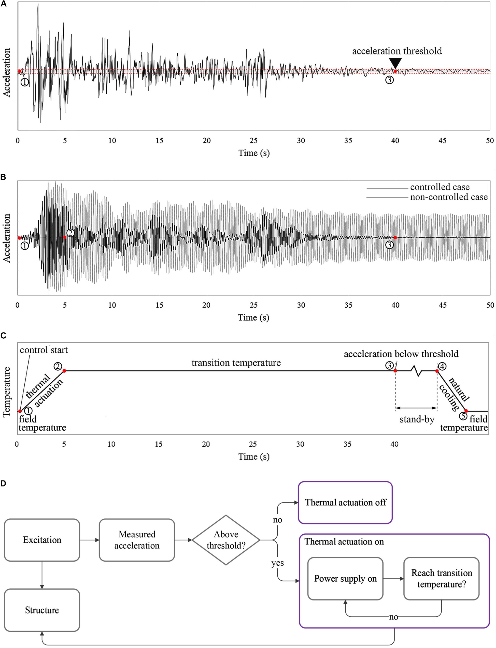
Figure 3. Semi-active control strategy: (A) ground acceleration; (B) non-controlled and controlled acceleration response; (C) joint temperature control law; (D) control strategy flow-chart.
Thermal Actuation
Generally, the temperature increase rate through thermal actuation depends on the type of heat transfer technology and activation stimulus of the SMP material (e.g., resistive and magnetic actuation). Assuming thermal actuation through resistive heating, the energy required to actuate the joint from ambient to transition temperature is:
where c is the specific heat capacity of the joint core material and ΔT is the required temperature change. The heat energy generated through resistive heating is:
where U is the power supply voltage; R is the resistance of the heating element; t is the heating time and is the power rating of the heating element. If heat transfer time and energy dissipation are ignored, let Q1=Q2. For the case studies considered in this work, the average mass of the joints is 9 kg. Assuming the specific heat capacity of SMP joint core is 1.4 kJ/ (kg°C), a rough estimate of the heat energy it takes to actuate the joint from ambient (25°C) to transition temperature (65°C) is 504 kJ. Assuming an appropriate power supply, five heating elements with a power rate of 20 kW suffice to limit the required heating time to 5 s.
Note that a transition temperature of 65°C is specific to the type of SMP that is adopted in this study which was selected primarily based on commercial availability. However, there exist several other SMP materials which feature a transition temperature that varies from 10°C to 178°C (Kusy and Whitley, 1994; Takahashi et al., 1996; Kumar et al., 2014). The SMP material specifics can be therefore chosen depending on location to minimize control effort and energy requirements by limiting interference with field temperature and the effect of seasonal temperature variation.
Case Study A: Truss Bridge
Model Features
Structural Model
The structure considered in this study is a simply supported planar truss which is designed as a truss bridge reduced to two dimensions. Figure 4A shows dimensions and support conditions. The span and rise of the truss are 8 and 0.5 m, respectively. The structure is equipped with seven variable stiffness and damping joints which are indicated by the yellow contour lines in Figure 4A. The adaptive joints are installed at all nodes except for the supports. The finite element model comprises beam elements of type BEAM188 for the chords and bracings as well as solid elements of type SOLID186 for the joints. The beam element material is structural steel S355. The beams have a 60 mm × 60 mm square hollow section and a wall thickness of 8 mm. The joint element material is the SMP material described in section “Variable Stiffness and Damping Joint.” Each solid element is a cuboid with edges of approximately 20 mm to mesh the joint geometry. The joint geometry has been obtained so that the beam elements connect to it through a section perpendicular to their axis. The beam sections are connected to the joint elements through a fixed contact. The reinforcement skin is modelled with “surface coating” elements of type SURF156 with a thickness of 5.16 mm which is obtained by stacking three layers of the SMP-aramid composite described in section “SMP-aramid Skin: Isotropic Elastic Material Model” (1.72 mm per layer). Since the skin is applied on the outer surface of the joint where the temperature is the lowest, it is assumed that the skin material is always in the glass state and therefore it has an elastic and temperature independent behavior. A modulus of 8320 MPa and an ultimate stress of 107 MPa is assumed for the reinforcement skin material based on experimental data (Wang et al., 2020).
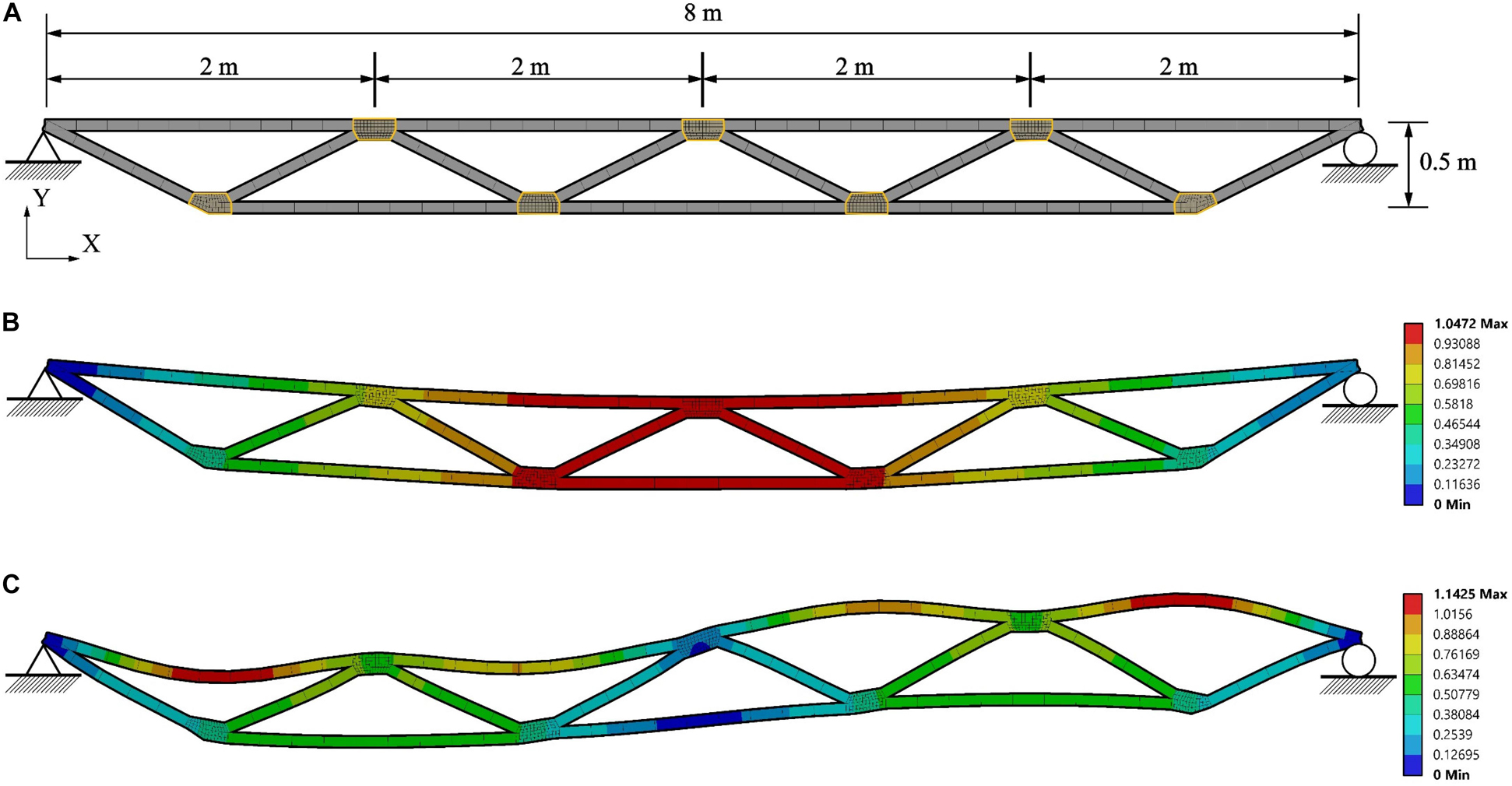
Figure 4. Truss bridge: (A) dimensions, support conditions, finite element mesh; (B) first and (C) second mode shapes.
Loading and Analysis Setting
The structure is subjected to a dead load which is uniformly distributed on the top chord members with an intensity of 200 kg/m2 and assuming 2 m of cover. Depending on the analysis type, additional loading will be applied. Static analysis is carried out under a uniformly distributed live load to evaluate the static response as the joint temperature increases. Transient analysis with mode superposition is carried out under resonance loading to test vibration control through frequency shift but ignoring damping variation due to viscoelastic effects. Full transient analysis using the viscoelastic material model is carried out to test the combined effect of frequency shift and damping variation on the structure dynamic response under a moving load. Since the location of the degree of freedom subjected to maximum displacement and acceleration changes with time, an average value among all degrees of freedom is taken because it is more representative of the dynamic response. The average value of the displacements is denoted as “deformation.”
In each analysis the joints are assumed to be actuated through resistive heating from ambient 25°C to transition temperature 65°C. Two types of thermal load are considered: (1) a constant thermal load is applied to increase the joint temperature in discrete steps; (2) following from the assumptions made in section “Thermal Actuation” with regard to the thermal actuation system, a time-linear thermal load is applied to increase the joint temperature from 25°C to 65°C in 5 s. Under constant thermal load the joints are assumed to be at a prescribed temperature when the load is applied and therefore the time it takes to increase the temperature is not taken into account. Under time-linear thermal load, time delays due to heating are included in the analysis.
All simulations are carried out in Ansys Workbench.
Static Analysis
In addition to the dead load defined in section “Model Features,” a uniformly distributed live load with an intensity of 350 kg/m2 and assuming 2 m of cover is applied on the top chord members. A comparison between with and without reinforcement skin is carried out. When the joints are actuated from 25°C to 65°C, the maximum static deformation of the structure increases from 44.7 to 1095.8 mm without reinforcement skin and from 23.2 to 33.5 mm with reinforcement skin. This clearly indicates the importance of applying the SMP-aramid reinforcement skin to reduce excessive deformation of the joints which occurs when they are thermally actuated to the transition range. Due to stiffness reduction caused by temperature increase, the maximum stress (von Mises) in the joint core decreases significantly from 11.1 to 1.2 MPa. Conversely, the maximum stress (von Mises) in the skin increases from 57.1 to 88.2 MPa.
Frequency Shift and Damping Variation
Joint stiffness variation causes a simultaneous shift of the structure natural frequencies and a damping variation. In this section these two effects are studied separately. Modal analysis is carried out using the thermo-elastic material model for the joints to evaluate the frequency shift caused by joint stiffness variation but ignoring frequency dependent effects. A free vibration test is carried out through full transient analysis using the viscoelastic material model for the joints in order to evaluate how the damping varies due to viscoelastic effects.
Frequency Shift
The first and second modes are observed as the joints are actuated from ambient to transition temperature (25–65°C). The natural frequencies and frequency shifts are indicated by ω1 − Sω1 and ω1 − Sω2 for the first and second mode, respectively. Results are given in Table 1. Due to the joint stiffness reduction, the structure natural frequency shifts up to 16.5% for the first mode and 10.24% for the second mode. The first and second mode shapes of the truss at 25°C are shown in Figures 4B,C.
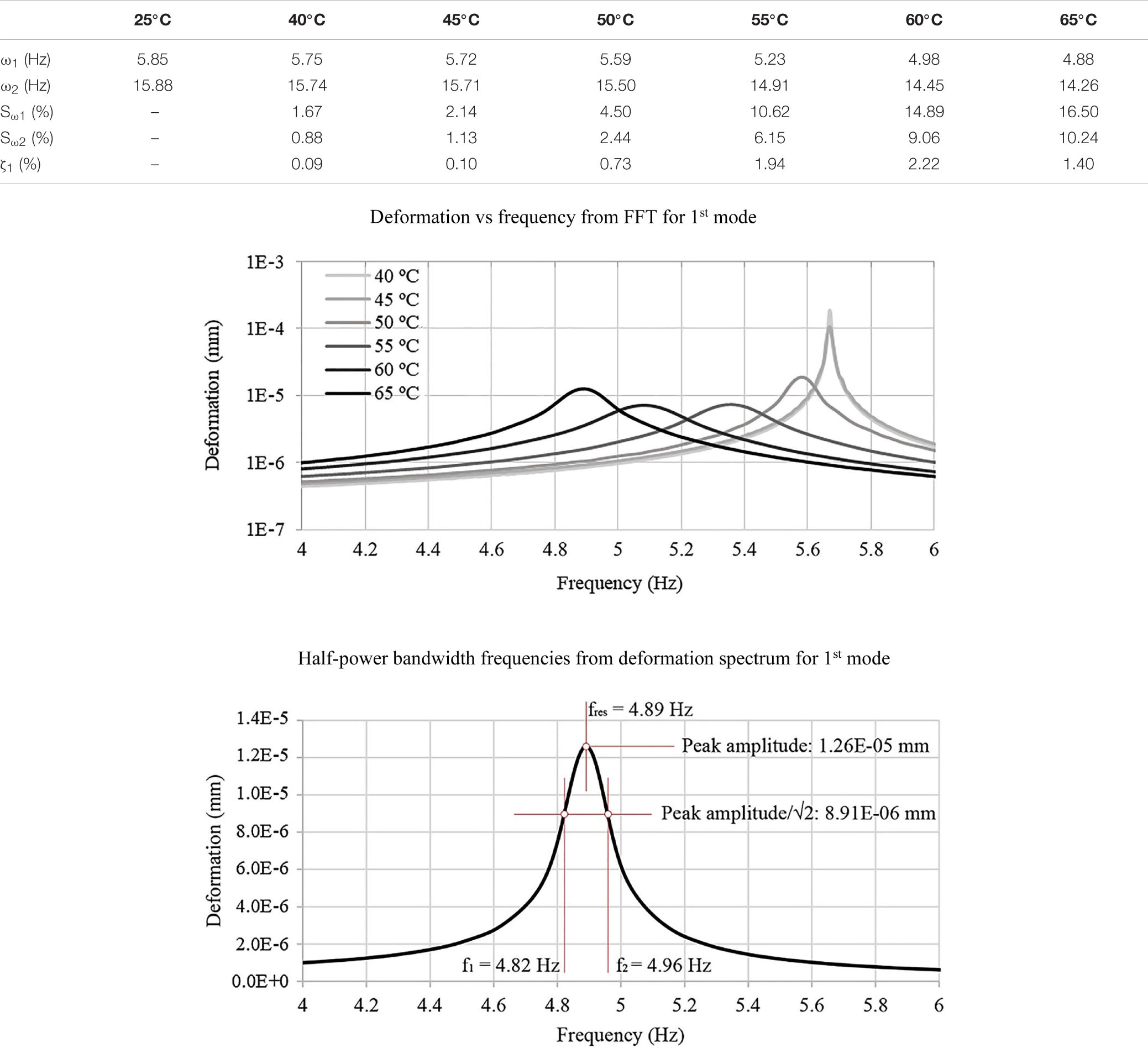
Table 1. Truss bridge: frequency, frequency shift, and first modal damping ratio.
Damping Variation
To quantify the damping variation caused by viscoelastic effects, a free vibration test is simulated. The joints are actuated from ambient to transition temperature (25°C–65°C). A 1 N impulse is applied in the middle of the bottom chord elements for 0.01 s in order to excite the first mode. The average deformation as a function of time for 40°C, 45°C, 50°C, 55°C, 60°C, and 65°C is shown in Supplementary Figure A1. The deformation vs. frequency curves shown in Table 1 are obtained from Fast Fourier transform (FFT). The peak indicates the structure natural frequency which reduces (shift to the left) when the joint temperature increases from 40°C to 65°C. Results from the free vibration test simulation in terms of frequency shift are in good accordance to what has been observed through modal analysis. At 40°C, the first mode frequency computed through modal analysis and FFT is 5.75 and 5.67 Hz, respectively. The difference in percentage terms is 1.4%. At 55°C, this difference reaches a maximum value of 2.5% (5.23 Hz from modal analysis and 5.36 Hz from FFT).
The half-power bandwidth method is employed to compute the damping ratio. This method can be applied to a multi-degree-of-freedom system when the modes are well-separated. For un-normalized spectra, the damping ratio ζ can be computed from Eq. 4 (Butterworth et al., 2004). It is assumed that half the total power dissipation occurs between f1 and f2 which are the frequencies corresponding to an amplitude of where fres is the frequency corresponding to the peak (i.e., resonance) (Butterworth et al., 2004).
The half-power bandwidth frequencies for the first mode at 65°C and the damping ratios at different temperatures are given in Table 1. The structure damping increases by up to 2.22% from undamped conditions (25°C) as the joints are actuated to 60°C and then it decreases as the temperature increases further. This trend is in accordance to what has been observed in section “Material Characterization.” Above transition temperature (65°C) damping decreases because the SMP material leaves the viscoelastic region and it enters the rubbery state (elastic). This explains why the peak amplitude for the deformation vs. frequency curve at 65°C is higher than that at 60°C (Table 1). At 65°C, the damping ratio (1.4%) is lower than that of 60°C (2.22%), hence the peak amplitude is higher.
Vibration Control Under Resonance Loading
Mode superposition analysis is carried out to evaluate dynamic response mitigation under resonance loading through frequency shift. A sinusoidal load qs = A sin(2πωet) with an amplitude A = 500 N is linearly distributed on the top chord elements in order to excite the first mode. The excitation frequency is identical to the structure first natural frequency at 25°C ω1 = ωe = 5.85 Hz. Figure 5 shows the average deformation vs. time at 25°C, 45°C, 50°C, 55°C, 60°C, and 65°C. At 25°C, the deformation amplitude of the truss increases steadily because of resonance. When the joints are actuated to 45°C, the deformation peak decreases significantly due to a 2.14% frequency shift (see Table 1). As the temperature increases, the frequency shift increases and therefore the average deformation peak amplitude reduces by 82% (from 141 mm after 5 s at 25°C to 25 mm at 65°C). In addition, since the natural frequency reduces, the period of the single cyclic pulsation (the so called “beat”) Tb = 1/|ω1−ωe| also reduces progressively as shown in Figures 5C–F.
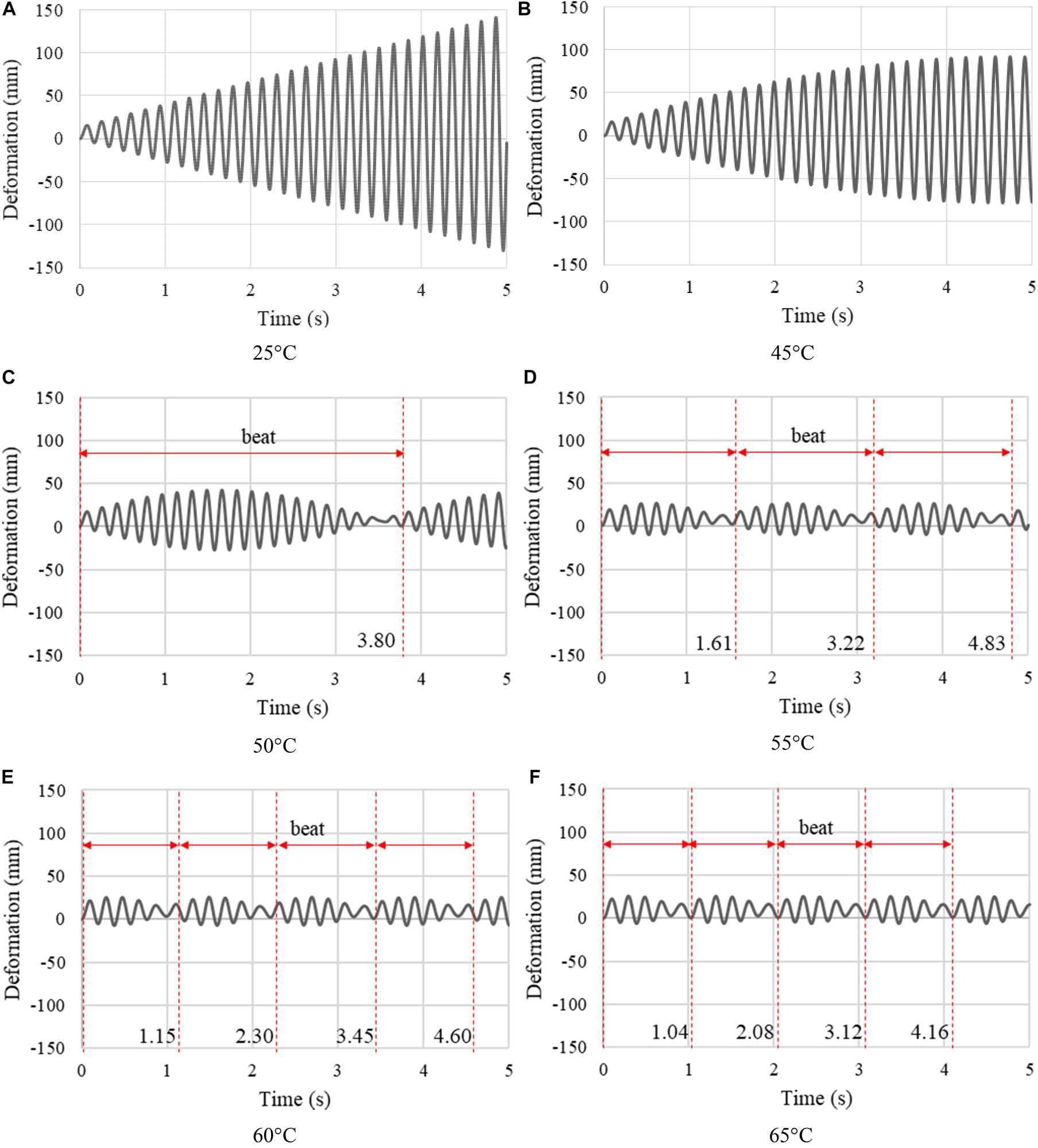
Figure 5. Truss bridge: (A–F) Average deformation vs. time at 25°C, 45°C, 50°C, 55°C, 60°C, and 65°C under resonance load.
As the stiffness of the joint decreases with the temperature, the maximum stress (von Mises) in the joint decreases from 91 MPa at 25°C to 1.2 MPa at 65°C. Since the reinforcement skin is stiffer than the joint, it takes most of the stress which also decreases as the temperature increases due to the reduction of deformation caused by the frequency shift. The maximum stress in the reinforcement skin decreases from 477 MPa (resonance case) to 315 MPa at 40°C, 256 MPa at 45°C, 147 MPa at 50°C, 97 MPa at 55°C, 93 MPa at 60°C, and 94 MPa at 65°C. Note that, when the joints are actuated to 55°C, the stress decreases to a value which is lower than the skin material ultimate stress of 107 MPa.
Vibration Control Under Moving Load
A moving load of 350 kg/m2 is applied on the top chord elements. The load moves from the pin (left side in Figure 6) to the roller support (right side) and then backwards. Two speeds are tested: 1× = 1.4 m/s (walking pace) and 10× = 14 m/s (typical car speed on residential roads 50 km/h). The load is applied on each top chord element (2 m in length). To simulate the transition from one element to the next, the load intensity varies from 0 to 350 kg/m2 (max) as the application position approaches the middle of the element and then from 350 kg/m2 (max) to 0 when the application position reaches the element end. This load profile is illustrated in Figure 6 for the 1.4 m/s speed case.
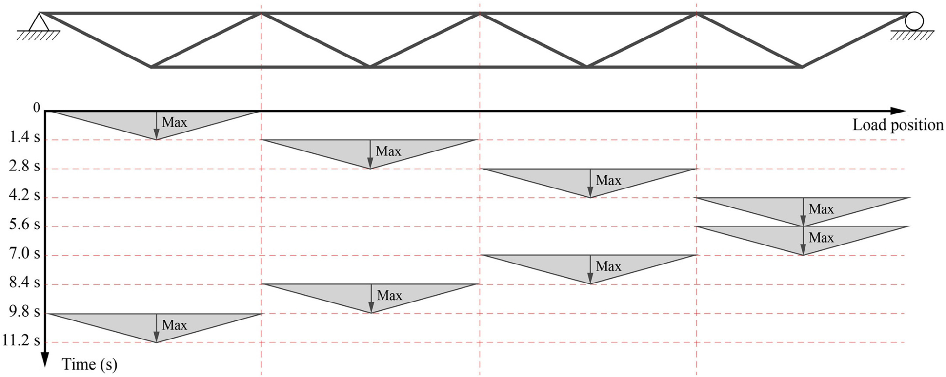
Figure 6. Truss bridge: moving load.
Mitigation of the dynamic response through frequency shift and damping variation is evaluated. Full transient analysis is carried out using both the thermo-elastic and viscoelastic material model. Figure 7 shows the plots of the average acceleration and deformation vs. time, under 1× and 10× speed load cases when the joints are actuated to 40°C, 55°C, and 65°C.
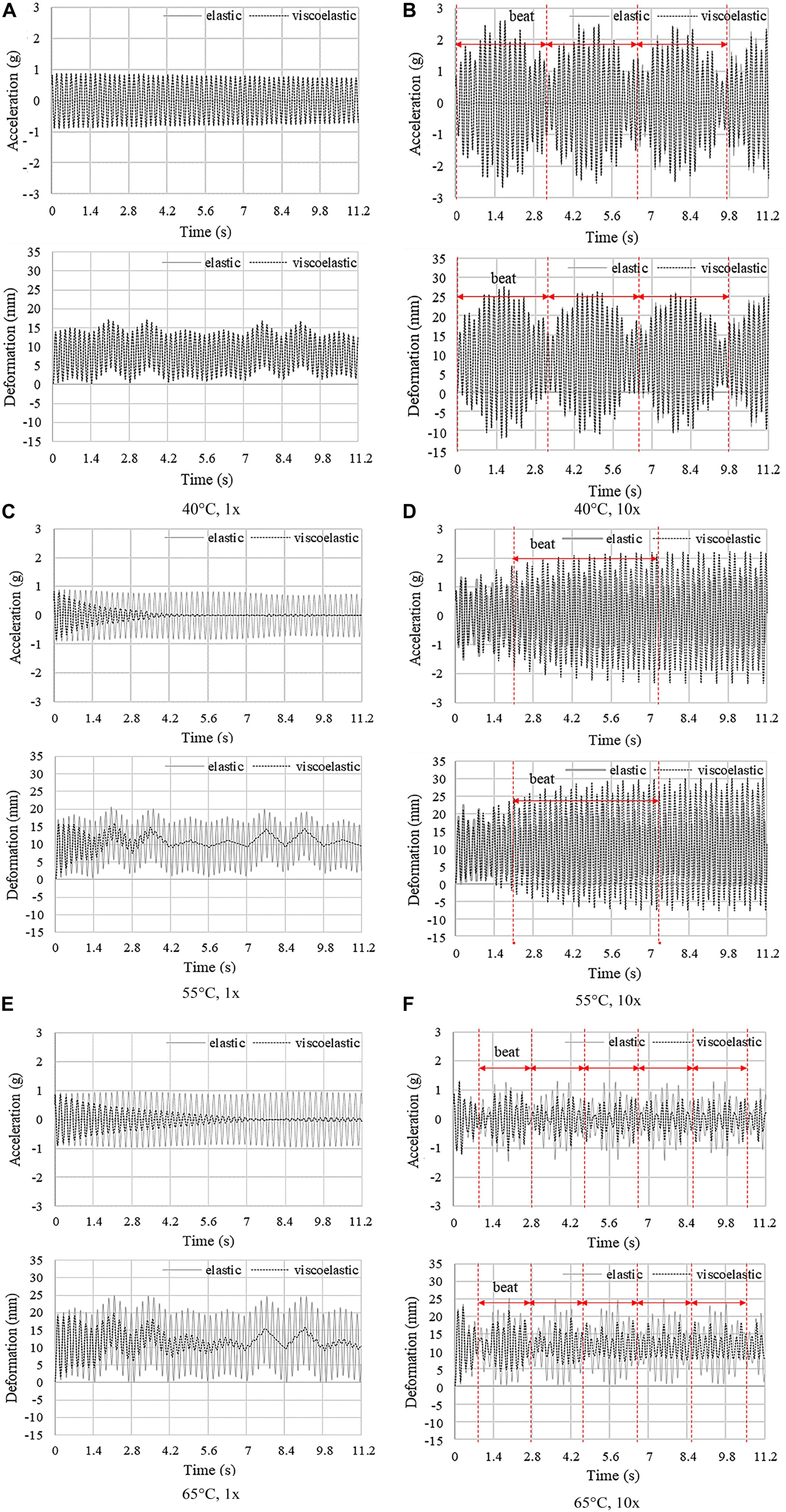
Figure 7. Truss bridge: average deformation and acceleration vs. time at 40°C, 55°C, and 65°C under 1×-speed load (A,C,E) and under 10×-speed load (B,D,F).
Under the 1× speed load, at a temperature lower than 50°C, the dynamic response obtained using the elastic and viscoelastic material model is similar (Figure 7A). However, when the joints are actuated to and above 55°C (Figure 7C), the dynamic response reduces significantly only for the viscoelastic case which accounts for the increase of damping that occurs because the SMP is in the viscoelastic region (from 50°C to 65°C). At 60°C, the average acceleration and deformation peak amplitudes reduce by 95% and 20%, respectively, compared to the non-controlled case (25°C) after 4.2 s. Instead, for the elastic case, the deformation peak amplitude increases due to the stiffness reduction of the joints. In this case, frequency shift does not contribute significantly to vibration suppression while the increase of damping due to viscoelastic effects is dominant.
A different behavior is observed under the 10× speed load. The dynamic response for the elastic and viscoelastic case features a similar beat when the joints are actuated to 40°C (Figure 7D). When the joints are actuated to 55°C, resonance conditions occur due to the frequency shift. The deformation and acceleration for the viscoelastic case are larger than those for the elastic case because the excitation frequency is the closest to the natural frequency at 54°C using the viscoelastic model. Instead, using the elastic model, the excitation frequency is the closest to the natural frequency at 52°C. When the joints are actuated to 65°C (Figure 7F), the dynamic response reduces for both elastic and viscoelastic case, and more prominently for the latter due to the combined effect of frequency shift and damping increase. The average acceleration and deformation peak amplitudes reduce by 69% and 22%, respectively, compared to the non-controlled case (25°C) after 4.2 s.
Vibration Control Under Moving Load Considering Time Delays Due to Heating
In order to account for time delays due to heating, vibration control simulation under the 1× speed moving load is carried out by applying a time-linear thermal load that increases the joint temperature from 25°C to 65°C in 5 s (see assumptions regarding the thermal actuation system given in section “Thermal Actuation”). Acceleration and displacement responses are shown in Figures 8A,B, respectively. The non-controlled case (25°C) is indicated by a gray curve while controlled cases with constant thermal load at 65°C and linear thermal load (25°C–65°C in 5 s) are indicated by a black-dashed and an orange curve, respectively. During the first 3 s (25°C–50°C), since the joint core material has not entered the viscoelastic region (see Figure 2A), the structure response is very similar to the non-controlled state. From 3 to 5 s (50°C–65°C) the core material is in the viscoelastic region; the structure response starts to reduce rapidly owing to the increase of damping. Compared to the constant thermal load at 65°C, the acceleration decay is faster under the time-linear load because as discussed in section “Frequency Shift,” the damping ratio is higher at 55°C and 60°C than that at 65°C. After 5 s, when the joint core material reaches the transition temperature of 65°C, the structure response becomes very similar to that controlled by applying a constant thermal load at 65°C. Considering a time delay of 5 s, results in a marginally higher controlled acceleration compared to the case without time delay. Similar conclusion applies to the displacement response. Note that, when the linear thermal load is applied, the peak displacements are smaller than those under the constant thermal load because the structure is stiffer in the first 5 s.
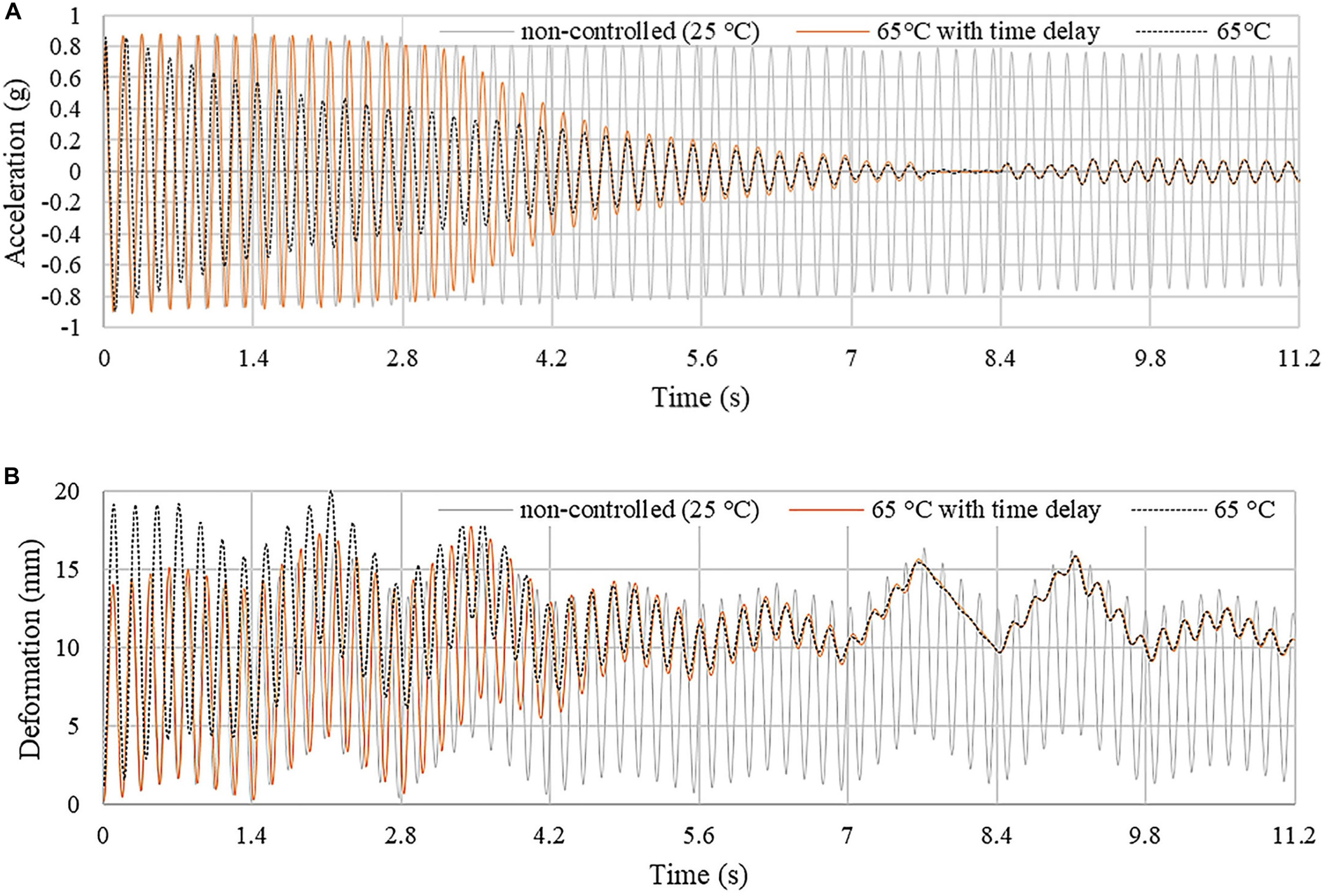
Figure 8. Truss bridge: (A) acceleration and (B) displacement response. The joints are actuated through a time-linear thermal load which increases the core temperature from 25°C to 65°C in 5 s.
When considering time delay due to heating, vibration suppression becomes effective once the joint core material enters the viscoelastic region.
Joint and Element Utilization
Supplementary Figure A2 shows the plot of the average von Mises stress vs. strain for the joint core and reinforcement skin at 40°C, 55°C, and 65°C under the 1× speed load. At 40°C the behavior of the SMP core material is almost purely elastic hence the stress vs. strain curve is a straight line. When the joints are actuated to 50°C and above, stress and strain are out of phase and hence the curves feature hysteresis loops. The stress in the joint core decreases as the temperature increases due to loss of stiffness. The SMP-aramid skin is modeled as an elastic material and therefore the stress vs. strain curve is linear at all temperatures. As expected, the stress in the reinforcement skin increases when the temperature increases due to loss of stiffness of the joint core.
Maximum demand over capacity for the truss elements under tension, compression, bending, shear and buckling are evaluated using BS EN 1993-1-1 (Eqs 5–9) from ambient to transition temperature (25°C–65°C) under the moving load (1× speed). The utilization factors given in Table 2 are obtained from full transient analysis using the viscoelastic material model.
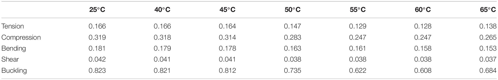
Table 2. Utilization factors for chord and bracing elements.
NEd and MEd are the maximum for tension/compression and bending moment computed through transient analysis (1× speed load); Nt,Rd, Nc,Rd, and Mc,Rd are the tension, compression and moment resistance. χ and χLT are the reduction factors for axial and torsional buckling. The elements with the highest utilization are the top and bottom chord elements at mid span (Figure 4). Generally, element utilization decreases as the joints are actuated from ambient to 60°C and then increases slightly due to the decrease of damping when the SMP core approaches the rubbery state (see section “Material Characterization”). On average, the utilization factors reduce by 23% for tension and compression, 13% for bending, 10% for shear, and 26% for buckling at 60°C, with respect to the non-controlled state (25°C).
Case Study B: Four-Story Frame
Model Features
Structural Model
The structure considered in this study is a 6 m (width) × 16 m (height) planar frame which is designed as a 4-story building reduced to two dimensions. Figure 9A shows dimensions and support conditions. The frame is equipped with eight variable stiffness and damping joints which are installed at all nodes except for the supports. The adaptive joints, which are indicated by yellow contour lines, are fitted between the bracing and the floor beams without interrupting column continuity. The finite element mesh comprises elements of type BEAM188 for the columns and floor beams and elements of type SOLID186 for the joints. The beam element material is structural steel S355. The beams have a 200 mm × 200 mm square hollow section and a wall thickness of 10 mm. The joint element material is the SMP material described in section “Variable Stiffness and Damping Joint.” The joint elements and geometry have been modeled similarly to the truss bridge case study. The reinforcement skin is modeled with “surface coating” elements of type SURF156 with a thickness of 6.88 mm which is obtained by stacking four layers of the SMP-aramid composite described in section “SMP-aramid Skin: Isotropic Elastic Material Model” (1.72 mm per layer). The skin element material is the same of that used for the truss bridge case study.
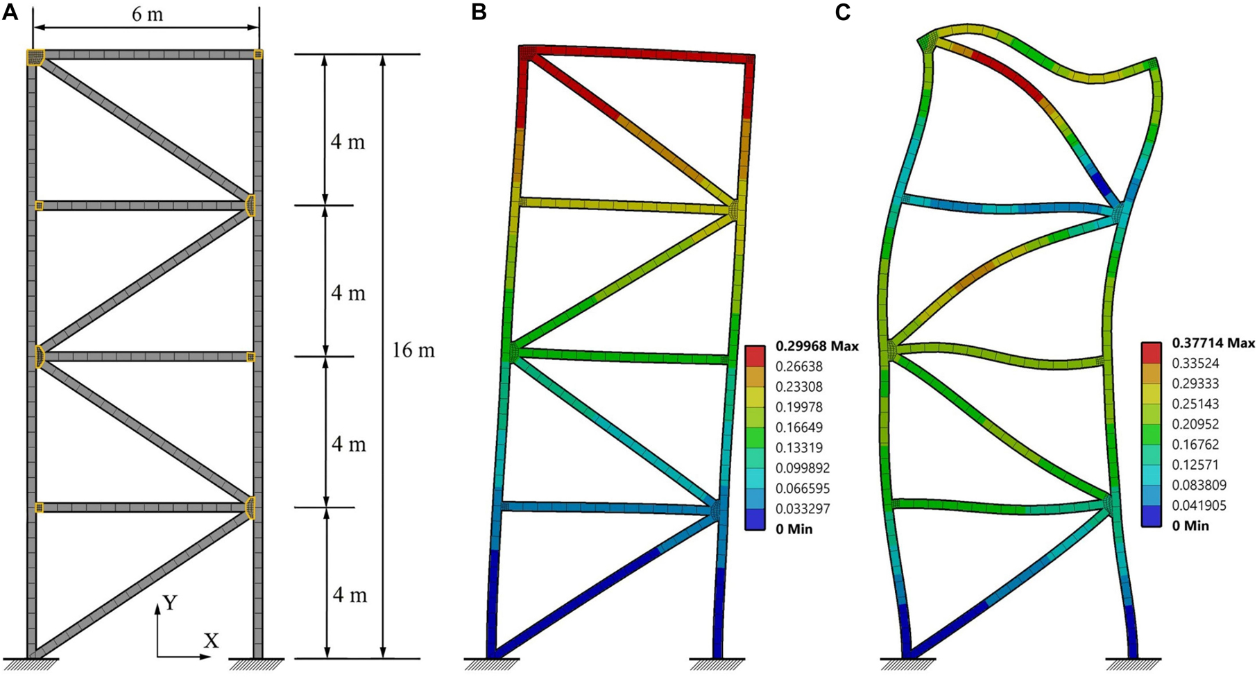
Figure 9. Four-story frame: (A) dimensions, support conditions, finite element mesh; (B) first and (C) second mode shapes.
Loading and Analysis
The structure is subjected to a dead load which is uniformly distributed on each floor beam with an intensity of 300 kg/m2 and assuming 6 m of cover. Full transient analysis using the viscoelastic material model is carried out to test vibration control under El-Centro earthquake loading. Since the location of the degree of freedom subjected to maximum displacement and acceleration changes with time, an average value among all degrees of freedom is taken because it is more representative of the dynamic response. The average value of the displacements is denoted as “deformation.”
In each analysis the joints are assumed to be actuated through resistive heating from ambient 25°C to transition temperature 65°C in discrete steps. The same types of thermal load considered in the truss bridge case study (section “Case Study A: Truss Bridge”) are applied here: (1) a constant thermal load is applied to increase the joint temperature in discrete steps; a time-linear thermal load is applied to increase the joint temperature from 25°C to 65°C in 5 s.
All simulations are carried out in Ansys Workbench.
Frequency Shift and Damping Variation
Modal analysis and a free vibration test have been carried out to evaluate frequency shift and damping variation for first and second modes. The joints are actuated from ambient to transition temperature (25–65°C). The free vibration test is carried out by applying a horizontal 1 N impulse force to the middle node of the left column elements in order to excite the first mode. Modal analysis is carried out using the thermo-elastic material model for the joints while the free vibration test is carried out through full transient analysis using the viscoelastic material model for the joints. The first two mode frequencies ω1, ω2, and frequency shifts Sω1, Sω2 are given in Table 3. Due to joint stiffness reduction, the structure natural frequency shifts up to 14.8% for the first mode and 15.7% for the second mode. The first and second mode shapes are shown in Figures 9B,C, respectively.
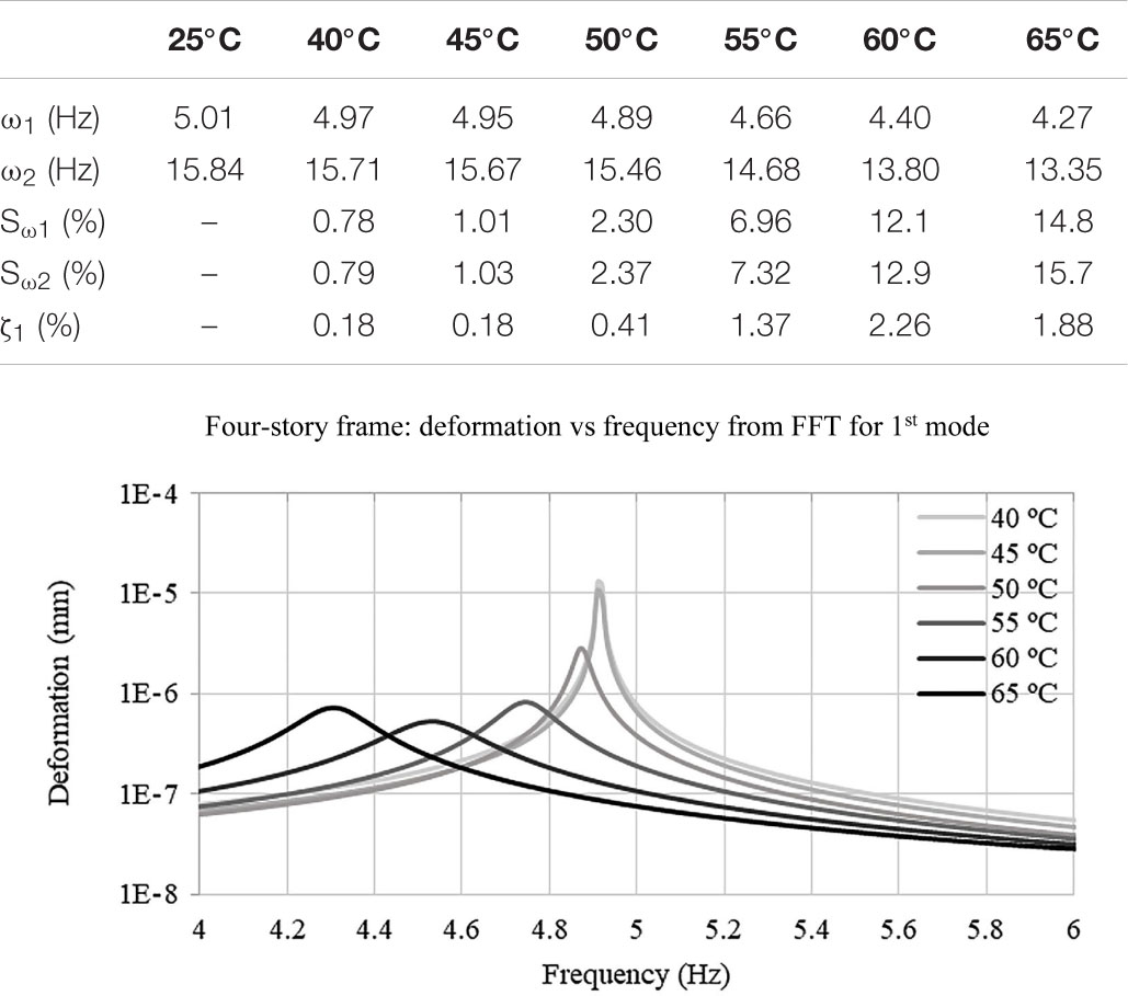
Table 3. Four-story frame: frequency, frequency shift, and first modal damping ratio.
The deformation vs. frequency curves for the first mode are shown in Table 3. At 40°C, the first mode frequency computed through modal analysis and FFT is 4.97 and 4.91 Hz, respectively. The difference in percentage terms is 1.2%. At 60°C, this difference reaches a maximum value of 3.0% (4.40 Hz from modal analysis and 4.53 Hz from FFT). The damping ratio ζ1 has been obtained through the half-power bandwidth method (Eq. 4). The damping ratio increases by up to 2.26% from undamped conditions (25°C) as the joints are actuated to 60°C and then it decreases as the temperature increases further. This explains why the peak amplitude for the deformation vs. frequency curve at 65°C is higher than that at 60°C. As observed previously (see section “Material Characterization”), above transition temperature (65°C) damping decreases, as the SMP material leaves the viscoelastic region and enters the rubbery state. The deformation vs. time curves for the free vibration test are shown in Supplementary Figure A3.
Vibration Control Under Earthquake Loading
Mitigation of the dynamic response under El Centro earthquake loading through frequency shift and damping variation is evaluated. The joints are actuated from ambient to transition temperature (25–65°C). Full transient analysis is carried out using both the thermo-elastic and viscoelastic material model for the joints.
Figure 10 shows the horizontal component (axis × in Figure 9) of the average acceleration (absolute) and deformation relative to the ground vs. time for all temperatures in the considered range 25°C, 40°C, 45°C, 50°C, 55°C, 60°C, and 65°C. For the elastic case, the dynamic response increases significantly at 45°C, 50°C, and at 60°C due to resonance. In the frequency range 4–5 Hz, the load has high energy components at 4.94, 4.89, and 4.38 Hz which are very close to the natural frequency at 45°C (4.95 Hz), 50°C (4.89 Hz), and 60°C (4.40 Hz), respectively. For the viscoelastic case instead, the dynamic response reduces significantly. The average acceleration (absolute) peak amplitude reduces from 1.6 g at 25°C to 0.6 g at 60°C. However, due to resonance conditions caused by the frequency shift, the response increases at 40°C and 45°C. When the temperature reaches 50°C, resonance is avoided, and the effect of damping becomes dominant. The slight increase of acceleration and deformation at 65°C is due to the decrease of damping as the SMP enters the rubbery state (see section “Material Characterization”). Despite this, at 65°C, the average acceleration (absolute) and deformation peak amplitudes reduce by 87% and 83%, respectively, compared to the non-controlled case (25°C) after 35 s.
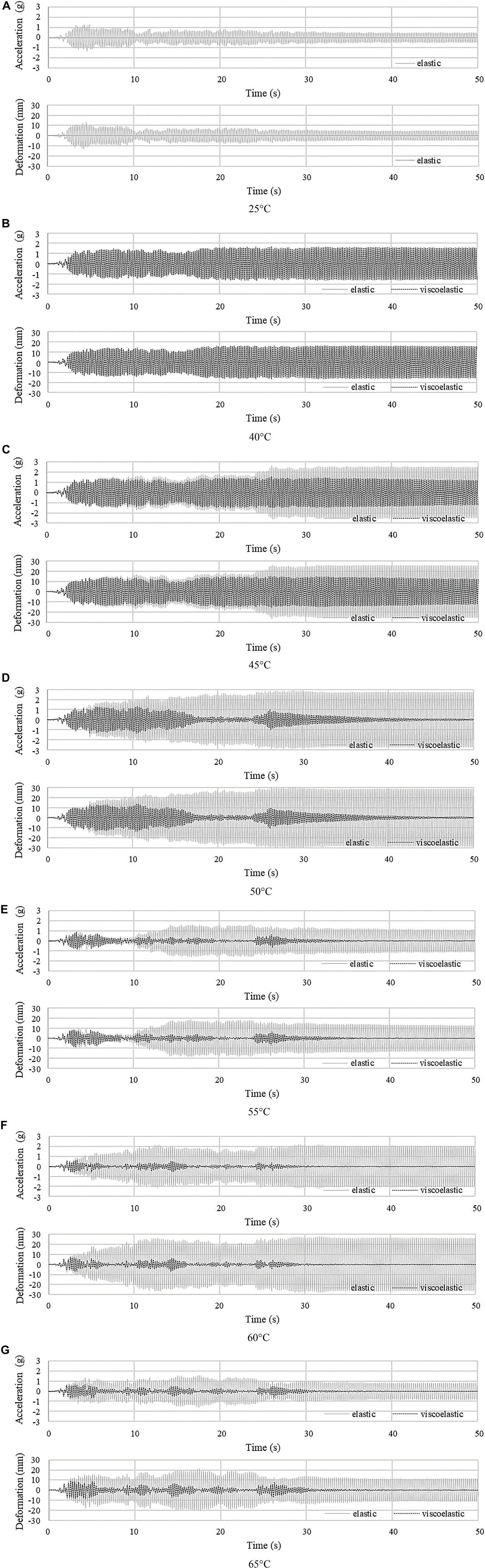
Figure 10. Four-story frame (A–G): average acceleration (absolute) and deformation (×component relative to the ground) vs. time under El Centro NS at 25°C, 40°C, 45°C, 50°C, 55°C, 60°C, and 65°C.
For seismic design, the inter-story drift dr should be contained within the damage limitation (European Committee for Standardization [CEN], 2004):
where h is the story height; ν is the reduction factor which accounts for the return period of the seismic action associated with damage limitation requirements and α is a factor which considers non-structural element types (i.e., elements that do not add stiffness to the structure). The recommended value for ν is 0.4 for buildings with importance class III and IV and 0.5 for importance class I and II. The recommended value for α is 0.005, 0.0075, and 0.01 for elements made of brittle materials, ductile elements, and fixed elements, respectively. The value for ν and α is set to 0.5 and 0.005, respectively. The maximum inter-story drift dr reduces from 6.3 mm between second and third floor at 25°C to 3.3 mm (48% reduction) between first and second floor at 60°C. However, due to resonance conditions caused by the frequency shift, dr reaches a maximum of 7.52 mm at 40°C between second and third floor. From Eq. 10 0.00282 < 0.005, hence the structure can be regarded as safe with respect to the damage limitation requirement under El Centro earthquake load.
The difference between results obtained using elastic and viscoelastic material models, indicates that the dynamic response reduces primarily because of the increase of damping. As the temperature of the joints is increased, the frequency shift might cause resonance. However, as shown by full transient analysis using the viscoelastic material model, the effect of damping becomes dominant when the joints are actuated to a temperature above 50°C, which causes a significant reduction of the dynamic response.
Vibration Control Under Earthquake Loading Considering Time Delay
In order to account for time delays due to heating, vibration control simulation under El Centro earthquake loading is carried out by applying a time-linear thermal load that increases the joint temperature from 25°C to 65°C in 5 s (see assumptions regarding the thermal actuation system given in section “Thermal Actuation”). Acceleration (absolute) and displacement responses are shown in Figures 11A,B, respectively. The non-controlled case (25°C) is indicated by a gray curve while controlled cases with constant thermal load at 65°C and linear thermal load (25°C–65°C in 5 s) are indicated by a black-dashed and an orange curve, respectively. As observed for the truss bridge case study, the structure response is very similar to the non-controlled state until the joint core is actuated to the viscoelastic region (first 3 s). After 5 s, when the joint core material reaches the transition temperature of 65°C, the structure response becomes very similar to that controlled by applying a constant thermal load at 65°C. When considering time delay due to heating, vibration suppression becomes effective once the joint core material enters the viscoelastic region.
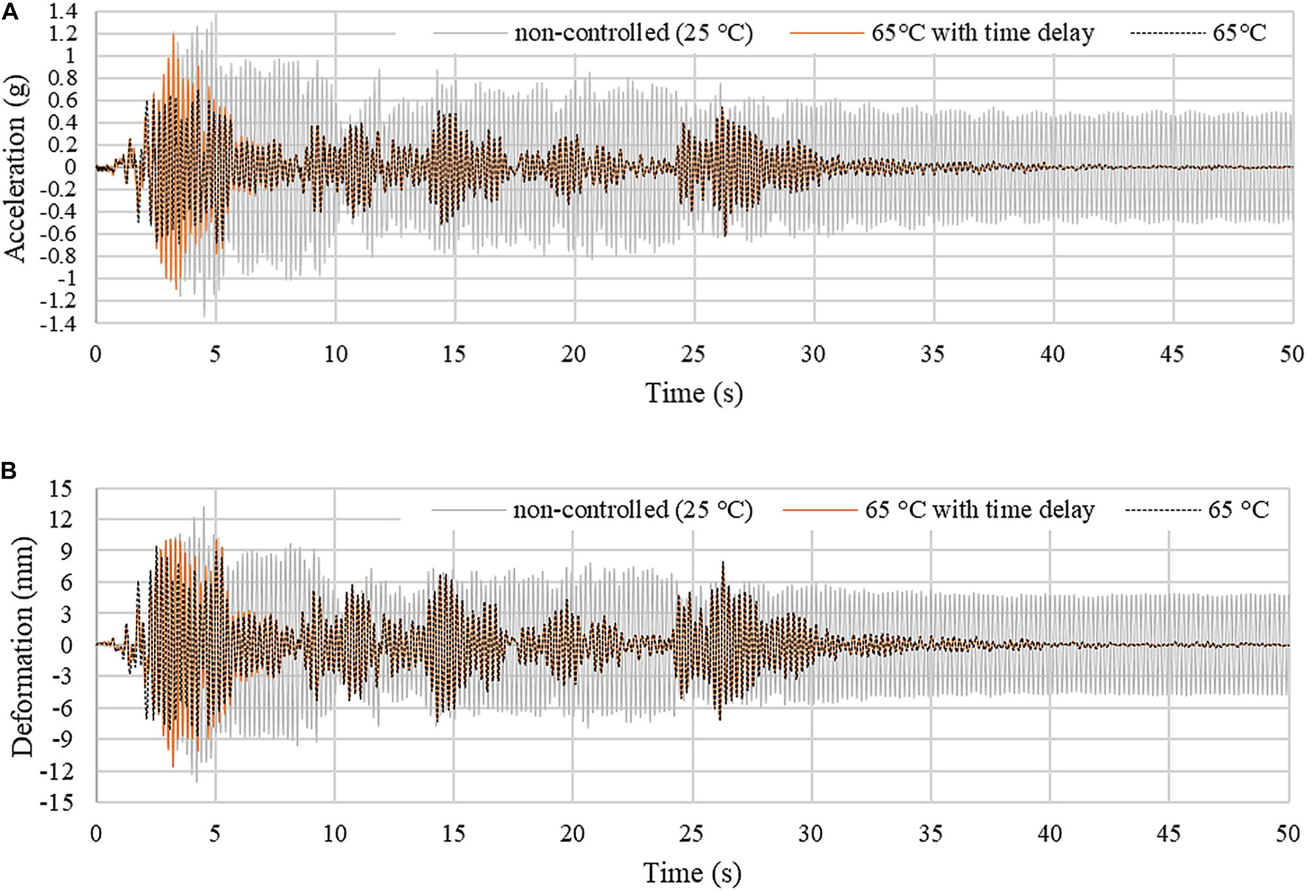
Figure 11. Four-story frame: (A) average acceleration (absolute) and (B) displacement response. The joints are actuated through a time-linear thermal load which increases the core temperature from 25°C to 65°C in 5 s.
Joint and Element Utilization
Similar considerations to the truss bridge case study apply with regard to the average von Mises stress vs. strain for the joint core and reinforcement skin (see Supplementary Figure A4). The SMP core behaves almost as a purely elastic material at 40°C and when the temperature increases, stress and strain go out of phase because the material enters the viscoelastic region. While the stress in the joint decreases, the stress in the reinforcement skin increases as the temperature increases due to the loss of stiffness of the joint core.
Maximum demand over capacity for the column, bracing and floor beam elements are evaluated using BS EN 1993-1-1 (Eqs 5–9). The utilization factors given in Table 4 are obtained through full transient analysis using the viscoelastic material model for the joints. The elements with the highest utilization are the first-floor bracing and right column elements. Generally, element utilization decreases as the joints are actuated from ambient to 60°C and then increases slightly due to the decrease of damping when the SMP core approaches the rubbery state (see section “Material Characterization”). The initial increase from 25°C to 40°C is caused by resonance conditions that occur due to frequency shift. On average, the utilization factors are reduced by 72% for tension, 56% for compression, 21% for bending, 25% for shear, and 53% for buckling at 60°C, with respect to the non-controlled state (25°C).
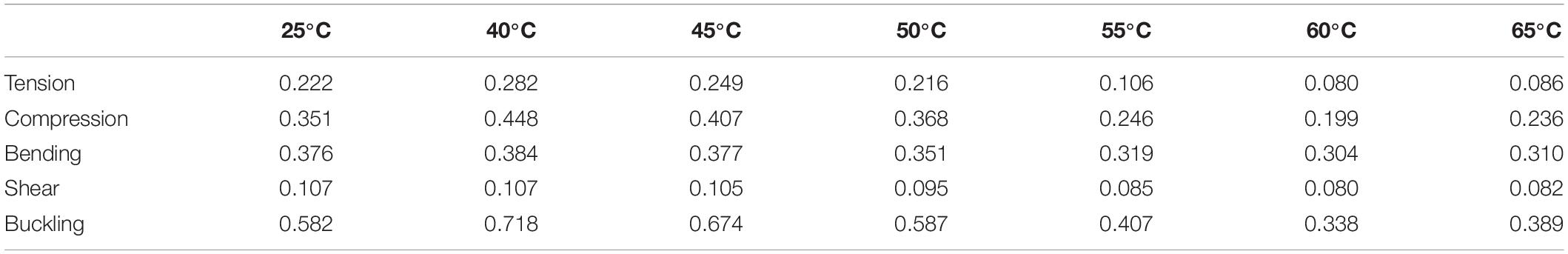
Table 4. Utilization factors for columns, bracing, and floor beams.
Discussion
This paper has presented a new semi-active vibration control device for truss and frame structures. The variable stiffness and damping joint discussed in this work comprises a SMP core which is reinforced by an SMP-aramid composite skin. The joints are assumed to be actuated through resistive heating. When the joints are actuated, the stiffness decreases and in parallel damping increases due to viscoelastic effects. The combined effect is a significant shift of the structure natural frequencies and an increase of damping. Simulations on a truss bridge and a four-story frame equipped with such variable stiffness and damping joints, have shown that this strategy is effective to mitigate the dynamic response under different loading scenarios including resonance, transient and earthquake loading.
Simulation results of a truss bridge under resonance loading have shown that the response is reduced significantly when the joints are actuated to 50°C and above. The average acceleration and deformation peak amplitudes reduce by 91% and 82% with respect to the non-controlled case (25°C). Under resonance loading, frequency shift caused by the joint stiffness reduction is effective to avoid resonance. When viscoelastic effects (frequency dependency) are ignored, the frequency shift due to joint stiffness reduction, might cause resonance if the excitation has important frequency components which are relatively close to the structure natural frequencies. However, when the effect of damping is considered through the viscoelastic material model, the overall effect is a significant reduction of the dynamic response. When the joints are actuated to 60°C, the damping ratio for the first mode increases by up to 2.2% and 2.3% from undamped conditions (25°C) for the truss bridge and four-story building, respectively.
For both case studies, the joints are assumed to be actuated through resistive heating from ambient 25°C to transition temperature 65°C. Thermal actuation of the joints has been simulated by applying two types of thermal load: (1) a constant thermal load is applied to increase the joint temperature in discrete steps without accounting for time delays due to heating; (2) a time-linear thermal load is applied to increase the joint temperature from 25°C to 65°C in 5 s. For the truss bridge under moving load, the average acceleration peak amplitude reduces by up to 95% with respect to the non-controlled case (25°C) in approximately 7 s with and without including time delays due to heating. Compared to the constant thermal load (65°C), the acceleration decay is faster under the time-linear load because the damping ratio is higher at 55°C and 60°C than that at 65°C. For the four-story building under earthquake loading and joints actuated to the transition temperature (65°C), the average acceleration (absolute) and deformation peak amplitudes and the inter-story drift reduce by 87%, 83%, and by 32%, respectively, with respect to the non-controlled case (25°C) after 35 s. Also in this case, the response reduction is very similar with and without accounting for time delays except in the first 5 s. When considering time delay due to heating, vibration suppression becomes effective once the joint core material enters the viscoelastic region (in this case after 3 s).
A transition temperature of 65°C is specific to the type of SMP adopted in this study which was selected primarily based on commercial availability. SMPs characteristics should be chosen appropriately depending on location in order to minimize control effort and energy requirements for thermal actuation by limiting interference with field temperature. For example, in cold regions, SMPs that feature a lower transition temperature should be selected. There exist several other SMP materials which feature a transition temperature that varies from 10°C to 178°C (Kusy and Whitley, 1994; Takahashi et al., 1996; Kumar et al., 2014). In addition, suitable insulation materials can be applied to the joints in order to reduce further interference with field temperature and the effect of seasonal temperature variation.
Conclusion
Dynamic response mitigation through control of variable stiffness and damping joints is possible due to a combination of frequency shift and damping variation. When the joints are actuated to the transition phase, the storage modulus (or stiffness) decreases while the material damping increases. When the excitation has a dominant frequency component that is close to the structure natural frequency, the response is reduced primarily through frequency shift. Conversely, when the excitation has several important frequency components, the response reduces primarily through the increase of damping due to viscoelastic effects. For the SMP material employed in this work, the response is reduced significantly using a control temperature between 55°C and 65°C. When considering time delay due to heating, vibration suppression becomes effective once the joint core material enters the viscoelastic region. SMPs characteristics should be chosen appropriately depending on location in order to minimize control effort and energy requirements for thermal actuation by limiting interference with field temperature.
On-going work will further elaborate and investigate the semi-active control strategy proposed in this paper through experimental testing on a small scale three-story spatial frame (650 mm × 650 mm × 1325 mm). In order to generalize the conclusions reached in this paper, future work will look into applying joint stiffness and damping control to mitigate the response of spatial structural configurations that have a complex layout.
Data Availability Statement
All datasets generated for in this study are included in the article/Supplementary Material.
Author Contributions
QW, GS, and PT set up research objectives and directions with contribution from KJ and AH. QW carried out method implementation with support of GS, KJ, and AH. QW carried out numerical studies with support of GS, AH, and PT and experimental testing with support of KJ. QW wrote the first version of the manuscript with support of GS. GS actively contributed to writing the final version of the manuscript. All authors contributed to manuscript revision, reviewed, and approved the final version.
Conflict of Interest
The authors declare that the research was conducted in the absence of any commercial or financial relationships that could be construed as a potential conflict of interest.
Acknowledgments
We thankfully acknowledge China Scholarship Council and 4TU Federation who provided funding for this research via 4TU Lighthouse Project.
Supplementary Material
The Supplementary Material for this article can be found online at: https://www.frontiersin.org/articles/10.3389/fbuil.2020.550864/full#supplementary-material
Supplementary Figure A1 | Truss bridge: (a–f) free vibration at 40°C, 45°C, 50°C, 55°C, 60°C and 65°C.
Supplementary Figure A2 | Truss bridge: stress vs. strain at 40°C, 55°C and 65°C in SMP core (a,c,e) and SMP-aramid skin (b,d,f).
Supplementary Figure A3 | Four-story frame: (a–f) free vibration at 40°C, 45°C, 50°C, 55°C, 60°C and 65°C.
Supplementary Figure A4 | Four-story frame: stress vs strain in SMP core (a,c,e) and SMP-aramid skin (b,d,f) at 40°C, 55°C and 65°C.
References
Bel Hadj Ali, N., and Smith, I. F. C. (2010). Dynamic behavior and vibration control of a tensegrity structure. Int. J. Solids Struct. 47, 1285–1296. doi: 10.1016/j.ijsolstr.2010.01.012
Bonello, P., Brennan, M. J., and Elliott, S. J. (2005). Vibration control using an adaptive tuned vibration absorber with a variable curvature stiffness element. Smart Mater. Struct. 14:1055. doi: 10.1088/0964-1726/14/5/044
Butterworth, J., Lee, J. H., and Davidson, B. (2004). “Experimental determination of modal damping from full scale testing,” in Proceedings of the 13th World Conference on Earthquake Engineering, Vancouver.
Campanile, L. F. (2005). Initial thoughts on weight penalty effects in shape-adaptable systems. J. Intell. Mater. Syst. Struct. 16, 47–56. doi: 10.1177/1045389X05046692
Djedoui, N., Ounis, A., Pinelli, J. P., and Abdeddaim, M. (2017). Hybrid control systems for rigid buildings structures under strong earthquakes. Asian J. Civil Eng. 18, 893–909.
dos Santos, F. A., and Cismaşiu, C. (2017). Adaptive underslung beam using shape-memory alloys for frequency-tuning. J. Intell. Mater. Syst. Struct. 28, 1260–1271. doi: 10.1177/1045389X16667558
dos Santos, F. A., Rodrigues, A., and Micheletti, A. (2015). Design and experimental testing of an adaptive shape-morphing tensegrity structure, with frequency self-tuning capabilities, using shape-memory alloys. Smart Mater. Struct. 24:105008. doi: 10.1088/0964-1726/24/10/105008
Du, H., Li, W., and Zhang, N. (2011). Semi-active variable stiffness vibration control of vehicle seat suspension using an MR elastomer isolator. Smart Mater. Struct. 20:105003. doi: 10.1088/0964-1726/20/10/105003
Dyke, S. J., Spencer, B. F Jr, Sain, M. K., and Carlson, J. D. (1996). Seismic response reduction using magnetorheological dampers. IFAC Proc. 29, 5530–5535. doi: 10.1016/S1474-6670(17)58562-6
European Committee for Standardization [CEN] (2004). Eurocode 8: Design of. (structures)for Earthquake Resistance-part 1: General Rules, Seismic Actions and Rules For Buildings, European Standard, 2004. Brussels: CEN.
Gall, K., Mikulas, M., Munshi, N. A., Beavers, F., and Tupper, M. (2000). Carbon fiber reinforced shape memory polymer composites. J. Intell. Mater. Syst. Struct. 11, 877–886. doi: 10.1106/EJGR-EWNM-6CLX-3X2M
Gkatzogias, K. I., and Kappos, A. J. (2016). Semi-active control systems in bridge engineering: a review of the current state of practice. Struct. Eng. Int. 26, 290–300. doi: 10.2749/101686616X14555429844040
Hu, J., Chen, W., Fan, P., Gao, J., Fang, G., Cao, Z., et al. (2017a). Uniaxial tensile tests and dynamic mechanical analysis of satin weave reinforced epoxy shape memory polymer composite. Polym. Test. 64, 235–241. doi: 10.1016/j.polymertesting.2017.09.038
Hu, J., Chen, W., Fan, P., Gao, J., Fang, G., Cao, Z., et al. (2017b). Epoxy shape memory polymer (SMP): material preparation, uniaxial tensile tests and dynamic mechanical analysis. Polymer Testing 62, 335–341. doi: 10.1016/j.polymertesting.2017.07.001
Huang, B., Zhang, H., Wang, H., and Song, G. (2014). Passive base isolation with superelastic nitinol SMA helical springs. Smart Mater. Struct. 23:065009. doi: 10.1088/0964-1726/23/6/065009
Kasai, K., Fu, F., and Watanabe, A. (1998). Passive control systems for seismic damage mitigation. J. Struct. Eng. 124, 501–512. doi: 10.1061/(ASCE)0733-9445(1998)124:5(501)
Kınay, G., and Turan, G. (2012). A hybrid control of seismic response by passive and semi-active control strategies. J. Eng. Sci. Des. 2, 27–36.
Kobori, T., Takahashi, M., Nasu, T., Niwa, N., and Ogasawara, N. (1993). Seismic response controlled structure with active variable stiffness system. Earth. Eng. Struct. Dyn. 22, 925–941. doi: 10.1002/eqe.4290221102
Kuder, I. K., Arrieta, A. F., Raither, W. E., and Ermanni, P. (2013). Variable stiffness material and structural concepts for morphing applications. Prog. Aerospace Sci. 63, 33–55. doi: 10.1016/j.paerosci.2013.07.001
Kumar, K. S., Khatwa, A. K., and Nair, C. R. (2014). High transition temperature shape memory polymers (SMPs) by telechelic oligomer approach. React. Funct. Polym. 79, 7–13. doi: 10.1016/j.reactfunctpolym.2014.02.008
Kusy, R. P., and Whitley, J. Q. (1994). Thermal characterization of shape memory polymer blends for biomedical implantations. Thermochim. Acta 243, 253–263. doi: 10.1016/0040-6031(94)85060-7
Lan, X., Liu, Y., Lv, H., Wang, X., Leng, J., and Du, S. (2009). Fiber reinforced shape-memory polymer composite and its application in a deployable hinge. Smart Mater. Struct. 18:024002. doi: 10.1088/0964-1726/18/2/024002
Ledezma-Ramirez, D. F., Ferguson, N. S., and Brennan, M. J. (2011). Shock isolation using an isolator with switchable stiffness. J. Sound Vib. 330, 868–882. doi: 10.1016/j.jsv.2010.09.016
Leng, J., Lan, X., Liu, Y., and Du, S. (2011). Shape-memory polymers and their composites: stimulus methods and applications. Prog. Mater. Sci. 56, 1077–1135.
Liao, G. J., Gong, X. L., Xuan, S. H., Kang, C. J., and Zong, L. H. (2012). Development of a real-time tunable stiffness and damping vibration isolator based on magnetorheological elastomer. J. Intell. Mater. Syst. Struct. 23, 25–33. doi: 10.1177/1045389X11429853
Lienhard, J., Schleicher, S., Poppinga, S., Masselter, T., Milwich, M., Speck, T., et al. (2011). Flectofin: a hingeless flapping mechanism inspired by nature. Bioinspirat. Biomimet. 6, 1–7. doi: 10.1088/1748-3182/6/4/045001
Lignarolo, L., Lelieveld, C., and Teuffel, P. (2011). “Shape morphing wind-responsive facade systems realized with smart materials,” in Proceedings of the International Adaptive Architecture Conference, London.
Liu, Y., Du, H., Liu, L., and Leng, J. (2011). Shape memory polymers and their composites in aerospace applications: a review. Prog. Mater. Sci. 56, 1077–1135. doi: 10.1016/j.pmatsci.2011.03.001
Liu, Y., Gall, K., Dunn, M. L., Greenberg, A. R., and Diani, J. (2006). Thermomechanics of shape memory polymers: uniaxial experiments and constitutive modeling. Int. J. Plast. 22, 279–313. doi: 10.1016/j.ijplas.2005.03.004
Menard, K. P. (2008). Dynamic Mechanical Analysis: A Practical Introduction. Boca Raton, FL: CRC Press. doi: 10.1201/9781420053135
Meng, H., and Li, G. (2013). A review of stimuli-responsive shape memory polymer composites. Polymer 54, 2199–2221. doi: 10.1016/j.polymer.2013.02.023
Mirfakhraei, S. F., Andalib, G., and Chan, R. (2019). Numerical investigation on toggled actuator forces in active vibration control system. Adv. Res. Civil Eng. 1, 16–35. doi: 10.1007/s42452-019-0210-4
Ohtori, Y., Christenson, R. E., Spencer, B. F. Jr., and Dyke, S. J. (2004). Benchmark control problems for seismically excited nonlinear buildings. J. Eng. Mech. 130, 366–385. doi: 10.1061/(ASCE)0733-9399(2004)130:4(366)
Preumont, A., and Seto, K. (2008). Active Control of Structures. Hoboken, NJ: John Wiley & Sons. doi: 10.1002/9780470715703
Reinhorn, A. M., Soong, T. T., Riley, M. A., Lin, R. C., Aizawa, S., and Higashino, M. (1993). Full-scale implementation of active control. II: installation and performance. J. Struct. Eng. 119, 1935–1960. doi: 10.1061/(ASCE)0733-9445(1993)119:6(1935)
Reksowardojo, A. P., Senatore, G., and Smith, I. F. (2019). Experimental testing of a small-scale truss beam that adapts to loads through large shape changes. Front. Struct. Sens. 5:93. doi: 10.3389/fbuil.2019.00093
Reksowardojo, A. P., Senatore, G., and Smith, I. F. C. (2020). Design of structures that adapt to loads through large shape changes. J. Struct. Eng. 146:04020068. doi: 10.1061/(ASCE)ST.1943-541X.0002604
Sarlis, A. A., Pasala, D. T. R., Constantinou, M. C., Reinhorn, A. M., Nagarajaiah, S., and Taylor, D. P. (2013). Negative stiffness device for seismic protection of structures. J. Struct. Eng. 139, 1124-1133. doi: 10.1061/(ASCE)ST.1943-541X.0000616
Senatore, G., Duffour, P., and Winslow, P. (2018a). Energy and cost analysis of adaptive structures: case studies. J. Struct. Eng. 144:04018107. doi: 10.1061/(ASCE)ST.1943-541X.0002075
Senatore, G., Duffour, P., and Winslow, P. (2018b). Exploring the application domain of adaptive structures. Eng. Struct. 167, 608–628. doi: 10.1016/j.engstruct.2018.03.057
Senatore, G., Duffour, P., and Winslow, P. (2019). Synthesis of minimum energy adaptive structures. Struct. Multidiscipl. Optimiz. 60, 849–877. doi: 10.1007/s00158-019-02224-8
Senatore, G., Duffour, P., Winslow, P., and Wise, C. (2018c). Shape control and whole-life energy assessment of an infinitely stiff prototype adaptive structure. Smart Mater. Struct. 27, 015022. doi: 10.1088/1361-665X/aa8cb8
Senatore, G., and Reksowardojo, A. P. (2020). Force and shape control strategies for minimum energy adaptive structures. Front. Built Environ. 6:105. doi: 10.3389/fbuil.2020.00105
Senatore, G., Wang, Q., Bier, H., and Teuffel, P. (2017). “The use of variable stiffness joints in adaptive structures,” in Proceedings of the IASS 2017, Hamburg.
Shu, Z., Zhang, J., and Nagarajaiah, S. (2017). Dimensional Analysis of Inelastic Structures with negative stiffness and supplemental damping devices. J. Struct. Eng. 143:04016184. doi: 10.1061/(ASCE)ST.1943-541X.0001658
Soong, T. T. (1988). State of the art review: active structural control in civil engineering. Eng. Struct. 10, 74–84. doi: 10.1016/0141-0296(88)90033-8
Soong, T. T., and Spencer, B. F. (2000). Active, semi-active and hybrid control of structures. Bull. New Zeal. Soc. Earth. Eng. 33:2000. doi: 10.5459/bnzsee.33.3.387-402
Spencer, B. F. Jr, Christenson, R. E., and Dyke, S. J. (1998). “Next generation benchmark control problem for seismically excited buildings,” in Proceedings of the Second World Conference on Structural Control, Kyoto.
Spencer, B. F., and Sain, M. K. (1997). Controlling buildings: a new frontier in feedback. IEEE Cont. Syst. Mag. 17, 19–35. doi: 10.1109/37.642972
Symans, M. D., and Constantinou, M. C. (1999). Semi-active control systems for seismic protection of structures: a state-of-the-art review. Eng. Struct. 21, 469–487. doi: 10.1016/S0141-0296(97)00225-3
Takahashi, T., Hayashi, N., and Hayashi, S. (1996). Structure and properties of shape-memory polyurethane block copolymers. J. Appl. Polym. Sci. 60, 1061–1069. doi: 10.1002/(SICI)1097-4628(19960516)60:7<1061::AID-APP18>3.0.CO;2-3
Wang, L., Wang, X., Li, Y., Lin, G., and Qiu, Z. (2017). Structural time-dependent reliability assessment of the vibration active control system with unknown-but-bounded uncertainties. Struct. Cont. Health Monit. 24:e1965. doi: 10.1002/stc.1965
Wang, Q., Senatore, G., Jansen, K., Habraken, A., and Teuffel, P. (2020). Design and characterization of variable stiffness structural joints. Mater. Design 187:108353. doi: 10.1016/j.matdes.2019.108353
Wang, Q., Senatore, G., Kaymenaki, V., Habraken, A., and Teuffel, P. (2018). “A vibration control strategy using variable stiffness joints,” in Proceedings of the IASS 2018, Boston.
Wang, Y., and Senatore, G. (2020). Minimum energy adaptive structures – All-In-One problem formulation. Comp. Struct. 236:106266. doi: 10.1016/j.compstruc.2020.106266
Xu, B., Wu, S. Z., and Yokoyama, K. (2003). Neural networks for decentralized control of cable-stayed bridge. J. Bridge Eng.. 8, 229–236. doi: 10.1061/(ASCE)1084-0702(2003)8:4(229)
Yang, G., Spencer, B. F. Jr., Carlson, J. D., and Sain, M. K. (2002). Large-scale MR fluid dampers: modeling and dynamic performance considerations. Eng. Struct. 24, 309–323. doi: 10.1016/S0141-0296(01)00097-9
Yang, J. N., Agrawal, A. K., Samali, B., and Wu, J. C. (2004). Benchmark problem for response control of wind-excited tall buildings. J. Eng. Mech. 130, 437–446. doi: 10.1061/(ASCE)0733-9399(2004)130:4(437)
Keywords: adaptive structures, variable stiffness and damping joint, frequency shift, viscoelastic material, structural dynamics, vibration control
Citation: Wang Q, Senatore G, Jansen K, Habraken A and Teuffel P (2020) Vibration Suppression Through Variable Stiffness and Damping Structural Joints. Front. Built Environ. 6:550864. doi: 10.3389/fbuil.2020.550864
Received: 10 April 2020; Accepted: 03 September 2020;
Published: 30 October 2020.
Edited by:
Dryver R. Huston, University of Vermont, United StatesReviewed by:
Shinta Yoshitomi, Ritsumeikan University, JapanChristian Málaga-Chuquitaype, Imperial College London, United Kingdom
Wei Song, University of Alabama, United States
Copyright © 2020 Wang, Senatore, Jansen, Habraken and Teuffel. This is an open-access article distributed under the terms of the Creative Commons Attribution License (CC BY). The use, distribution or reproduction in other forums is permitted, provided the original author(s) and the copyright owner(s) are credited and that the original publication in this journal is cited, in accordance with accepted academic practice. No use, distribution or reproduction is permitted which does not comply with these terms.
*Correspondence: Qinyu Wang, cS53YW5nMkB0dWUubmw=; Gennaro Senatore, Z2VubmFyby5zZW5hdG9yZUBlcGZsLmNo