 Sae Homma1
 Izuru Takewaki
- 1Department of Architecture and Architectural Engineering, Graduate School of Engineering, Kyoto University, Kyoto, Japan
- 2Graduate School of Advanced Science and Engineering, Hiroshima University, Hiroshima, Japan
An explicit limit for the overturning of a rigid block is derived on the input level of the triple impulse and the pseudo-triple impulse as a modified version of the triple impulse that are a substitute of a near-fault forward-directivity ground motion. The overturning behavior of the rigid block is described by applying the conservation law of angular momentum and the conservation law of mechanical energy (kinetic and potential). The initial velocity of rotation after the first impulse and the change of rotational velocity after the impact on the floor due to the movement of the rotational center are determined by using the conservation law of angular momentum. The maximum angle of rotation after the first impulse is obtained by the conservation law of mechanical energy. The change of rotational velocity after the second impulse is also characterized by the conservation law of angular momentum. The maximum angle of rotation of the rigid block after the second impulse, which is mandatory for the computation of the overturning limit, is also derived by the conservation law of mechanical energy. This allows us to prevent from computing complex non-linear time-history responses. The critical timing of the second impulse (also the third impulse timing to the second impulse) is featured by the time of impact after the first impulse. As in the case of the double impulse, the action of the second impulse just after the impact is employed as the critical timing. It is induced from the explicit expression of the critical velocity amplitude limit of the pseudo-triple impulse that its limit is slightly larger than the limit for the double impulse. Finally, it is found that, when the third impulse in the triple impulse is taken into account, the limit input velocity for the overturning of the rigid block becomes larger than that for the pseudo-triple impulse. This is because the third impulse is thought to prevent the overturning of the rigid block by giving an impact toward the inverse direction of the vibration of the rigid block.
Introduction
The rocking behavior of rigid blocks plays an important role in the evaluation of earthquake response of slender structures, monuments and furniture. Since many base-isolated high-rise buildings are being constructed in Japan and most isolators do not have tensile resistance, the seismic risk analysis of such slender structures is extremely focused recently.
The seismic rocking response of rigid blocks has been investigated for long time. The work was initiated by Milne (1885) and the detailed fundamental formulation was made by Housner (1963). Subsequently, Yim et al. (1980) did extensive investigation for versatile recorded ground motions following Housner (1963) and Ishiyama (1982) classified the seismic rocking responses into various types of nonlinear overturning response. Many investigations were conducted continuously so far (Spanos and Koh 1984, Hogan 1989, Shenton III and Jones 1991, Pompei et al., 1998, Zhang and Makris 2001, Prieto et al., 2004, Yilmaz et al., 2009, ElGawady et al., 2010, DeJong 2012, Dimitrakopoulos and DeJong 2012a; Dimitrakopoulos and DeJong 2012b). Rather recently, DeJong (2012) and Dimitrakopoulos and DeJong (2012a), Dimitrakopoulos and DeJong (2012b) investigated the rocking response of a rigid block in a more detailed manner. Casapulla et al. (2010) and Casapulla and Maione (2016) considered the multiple sequence of impulses for the rocking response of a rigid block and found the resonant response. They investigated the responses under two-type multiple impulses, i.e., with gradually increasing intervals for resonance and with equal intervals. Furthermore, Makris and Kampas (2016) derived an important fact related to the scale effect of blocks on the overturning limit level of sinusoidal inputs and earthquake ground motions.
It is well known that slender structures are affected strongly by impulsive pulse-type loading. After Northridge earthquake in 1994, Hyogoken-Nanbu earthquake in 1995 and Chi-Chi earthquake in 1999, many earthquake structural engineers and designers focused on the structural design under impulsive pulse-type earthquake ground motions (Hall et al., 1995; Sasani and Bertero 2000; Mavroeidis et al., 2004; Makris and Black 2004; Kalkan and Kunnath 2006; Xu et al., 2007; Rupakhety and Sigbjörnsson 2011; Champion and Liel 2012; Gerami and Sivandi-Pour 2014; Vafaei and Eskandari 2015; Khaloo et al., 2015). The principal part of such ground motions in the form of pulse-type waves represents the essential features of near-fault ground motions and such principal part was found to be classified into two types, i.e., the fling-step (fault-parallel) and forward-directivity (fault-normal) inputs (Mavroeidis and Papageorgiou 2003, Bray and Rodriguez-Marek 2004, Kalkan and Kunnath 2006, Mukhopadhyay and Gupta 2013a; Mukhopadhyay and Gupta 2013b; Zhai et al., 2013, Hayden et al., 2014, Yang and Zhou 2014, Kohrangi et al., 2018, Khansefid and Bakhshi 2019; Khansefid 2020). Afterward, it was made clear that the principal parts of the fling-step and forward-directivity inputs can be represented by some wavelets or a series of harmonic waves. Mavroeidis and Papageorgiou (2003) and some others pointed out the remarkable characteristics of this class of ground motions and provided some simple models. For example, the fling-step and forward-directivity inputs were characterized by two or three wavelets. It was reported that these pulse-type ground motions affect greatly the long-period building structures and large inelastic deformations could be concentrated to lower stories.
Recently Nabeshima et al. (2016) introduced a double impulse for the rocking vibration of a rigid block in order to substitute the response of the rigid block to near-field ground motions. The double impulse was proposed by Kojima and Takewaki (2015a), Kojima and Takewaki (2016), Taniguchi et al. (2016) to express the peculiar characteristics of near-fault ground motions. It was clarified that the double impulse enables the derivation of the closed-form maximum deformation of elastic-plastic SDOF systems. Nabeshima et al. (2016) derived a closed-form solution of the maximum critical response and a closed form expression of the limit input velocity level for the overturning. They also made clear that the critical timing of the second impulse is just after the impact on the ground. Taniguchi et al. (2017) extended the work of Nabeshima et al. (2016) dealing with the critical case (critical timing of the second impulse which gives the maximum response of a rigid block) to the non-critical case which is important in view of actual situations.
In the present paper, the triple impulse as a substitute of the forward-directivity input of near-fault ground motions and its modified version called the pseudo-triple impulse are treated and an explicit expression is obtained for the critical velocity amplitude limit of the triple impulse and the pseudo-triple impulse for overturning of a rigid block. The formulation for the pseudo-triple impulse is presented first and it is extended to the triple impulse.
Triple Impulse and Corresponding 1.5-Cycle Sinusoidal Wave
In this paper, it is aimed at modeling a principal part of a near-fault ground motion into a 1.5-cycle sinusoidal wave and then simplify such 1.5-cycle sinusoidal wave into a triple impulse following the references (Kojima and Takewaki 2015b) as shown in Figure 1. This is because the triple impulse has a simple characteristic and a straightforward derivation of its maximum response can be expected even for non-linear elastic responses based on an energy approach to free vibrations.
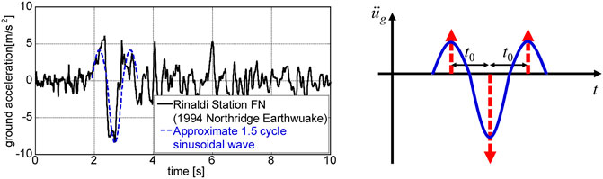
FIGURE 1. Modeling of principal part of near-fault ground motion into 1.5-cycle sinusoidal wave and modeling of such 1.5-cycle sinusoidal wave into triple impulse.
Following the reference (Kojima and Takewaki 2015b), consider a ground acceleration
where
In Eq. 2,
The velocity and displacement of the triple impulse and the corresponding modified sinusoidal wave can also be found in the reference (Kojima and Takewaki 2015b). It has been confirmed that the triple impulse is a good approximation of the corresponding 1.5-cycle sinusoidal wave even in the form of velocity and displacement.
The Fourier transform of the acceleration
While most of the previous methods utilize the equivalent linearization of the oscillating model for the unchanged input (see Figure 2A including an equivalent linear stiffness) or introduce detailed nonlinear structural models for which time-consuming response analysis is necessary, the method proposed in the works (Kojima and Takewaki 2015a; Kojima and Takewaki 2015b; Kojima and Takewaki 2016) and in this paper transforms the input into the triple or pseudo-triple impulse for the unchanged oscillating model (see Figure 2B). It should be pointed out that the rocking response of a rigid block includes a complicated phenomenon, e.g., strong nonlinearity, sudden energy loss at impact, the equivalent linearization may be difficult to apply.
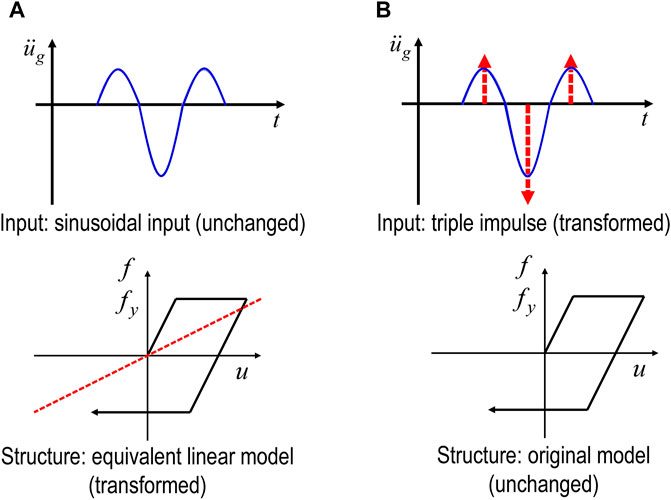
FIGURE 2. Comparison of new method of input transformation with conventional method of oscillating model transformation. (A) Conventional method: equivalent linearization of oscillating model for unchanged input, (B) New method: transformation of input into triple impulse for unchanged oscillating model.
Maximum Rotation Angle of Rigid Block Subjected to Critical Pseudo-Triple Impulse
Consider the rocking vibration of a rigid block (mass:
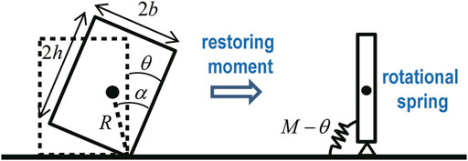
FIGURE 3. Modeling of rocking rigid block by rigid bar supported by non-linear elastic rotational spring with rigid initial stiffness and negative second slope (Nabeshima et al., 2016).
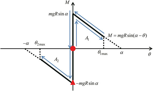
FIGURE 4. Moment-rotation relation for rocking response of rigid block and timing of impulses (red solid circle is the first impulse and red solid triangle is the second impulse) (Nabeshima et al., 2016).
In this paper, a pseudo-triple impulse as shown in Figure 5A is introduced where the third impulse in the triple impulse as shown in Figure 5B is neglected. This new model is treated because the third impulse may prevent the overturning of the rigid block by giving an impact toward the inverse direction of the vibration of the rigid block and the derivation of the explicit overturning limit for the triple impulse seems to be complicated and difficult. A scenario that the overturning occurs after the second impulse in the pseudo-triple impulse is employed here. This scenario seems valid because the input limit on the overturning corresponding to this scenario provides a lower limit in general. As for more detailed scenarios, see Ishiyama (1982) and Dimitrakopoulos and DeJong (2012b).
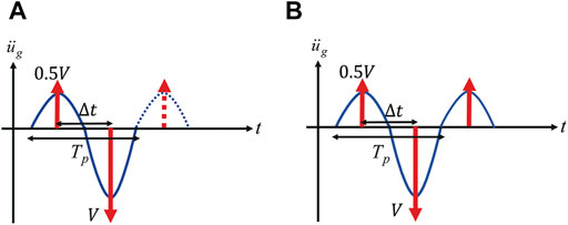
FIGURE 5. Input motions in numerical examples, (A) Pseudo-triple impulse, consisting of the first two impulses in triple impulse, and the corresponding equivalent modified 1.0-cycle sinusoidal wave, (B) Triple impulse and the corresponding equivalent 1.5-cycle sinusoidal wave.
Figure 6 shows the overview of the rocking vibration under the pseudo-triple impulse, consisting of the first two impulses in triple impulse. The critical acting timing of the second impulse is at the instant of impact where the velocity of rotation attains the maximum (see Nabeshima et al., 2016). Furthermore, it can be shown that critical timing is just after the impact because the velocity of rotation is reduced greatly at the impact. More detailed verification of the critical timing of the second impulse is shown in Nabeshima et al. (2016).
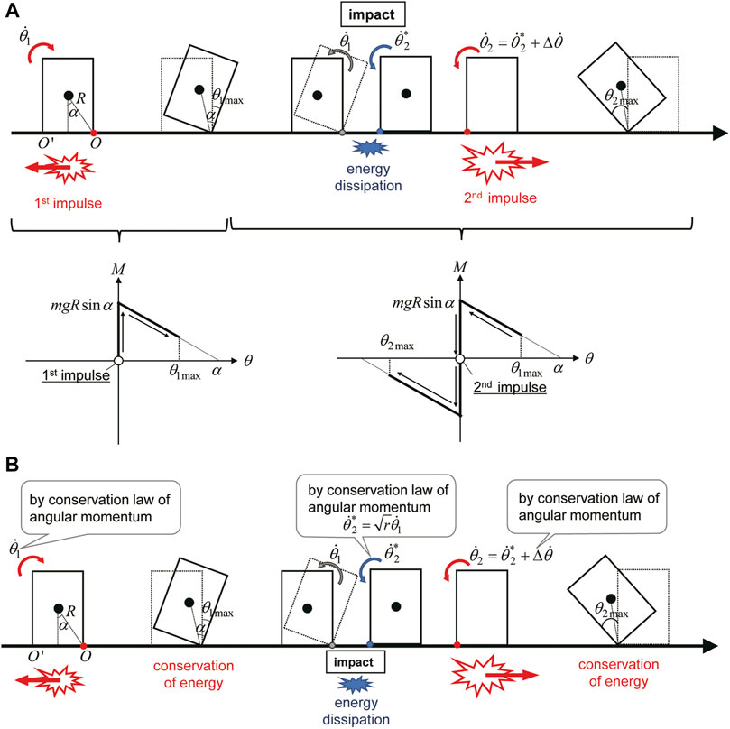
FIGURE 6. Overview of rocking vibration under pseudo-triple impulse, consisting of the first two impulses in triple impulse, (A) Overview of rocking vibration, (B) Mechanical energy conservation and angular momentum conservation.
When the angle of rotation of the rigid block is denoted by
The block rotates around an edge after the uplift from the ground. During the rotation, the position (potential) energy increases and the block resists the input acceleration.
Let
The first conservation law of angular momentum just after the first impulse and the first conservation law of mechanical energy after the first impulse can provide the initial rotational velocity
The second conservation law of angular momentum at the impact (
The conservation law of angular momentum just after the second impulse provides the rotational velocity change
Limit Input Level of Critical Pseudo-Triple Impulse Characterizing Overturning of Rigid Block
The overturning of the rigid block can be characterized by the attainment of
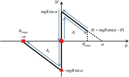
FIGURE 7. Moment-rotation relation for rocking response of rigid block and limit of overturning (Nabeshima et al., 2016).
The subscript “c1” indicates “critical” for the pseudo-triple impulse corresponding to the “1.0”-cycle sine wave. This limit input velocity is slightly larger than the limit for the double impulse derived in Nabeshima et al. (2016) (the coefficient 0.5 is a new addition). The critical timing
where
The limit critical timing
The above formulation was made for the case where the third impulse was disregarded. Figure 9 shows the overview of the rocking vibration under the triple impulse. The overturning limit for the complete triple impulse will be derived in the later section.
Numerical Examples and Discussion
Pseudo-triple Impulse and 1.0-Cycle Sinusoidal Wave
Numerical examples are introduced here to demonstrate the accuracy and reliability of the proposed method. Three numerical examples of rectangular columns are considered for the models with width (2b) = 1, 2, 4 m corresponding to the references (Makris and Kampas 2016; Nabeshima et al., 2016). The column height is changed parametrically.
Figure 8 shows the comparison of time-history responses
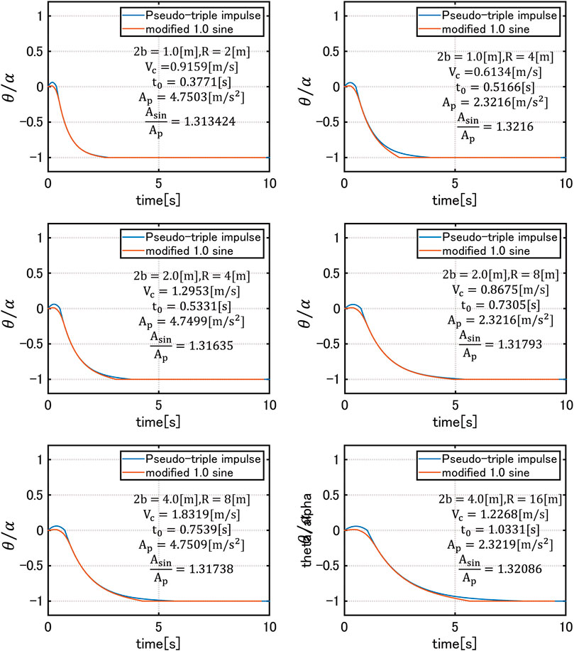
FIGURE 8. Comparison of time-history responses
Triple Impulse and 1.5-Cycle Sinusoidal Wave
It may be useful to investigate the response of a rigid block under the triple impulse to study the role of the third impulse which was disregarded in the pseudo-triple impulse. Figure 9 shows the overview of rocking vibration under the triple impulse from the viewpoint of mechanical energy conservation and angular momentum conservation.
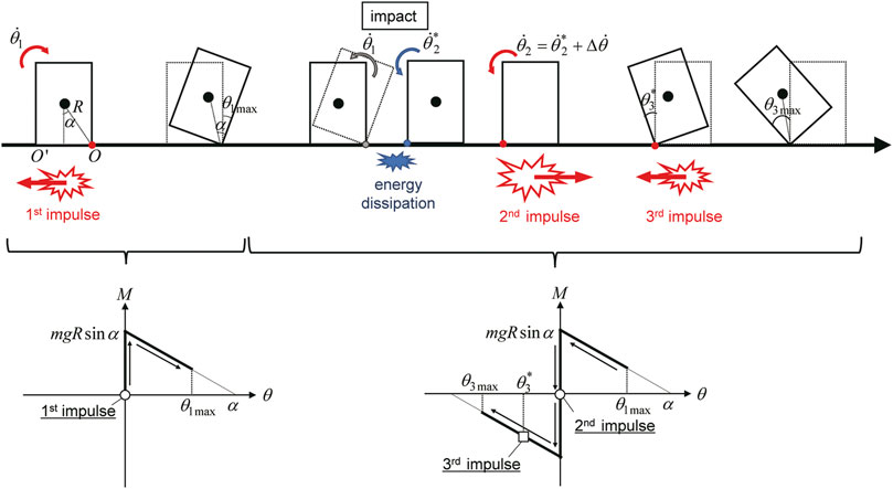
FIGURE 9. Overview of rocking vibration under triple impulse from the viewpoint of mechanical energy conservation and angular momentum conservation.
Figure 10 shows the comparison of time-history responses
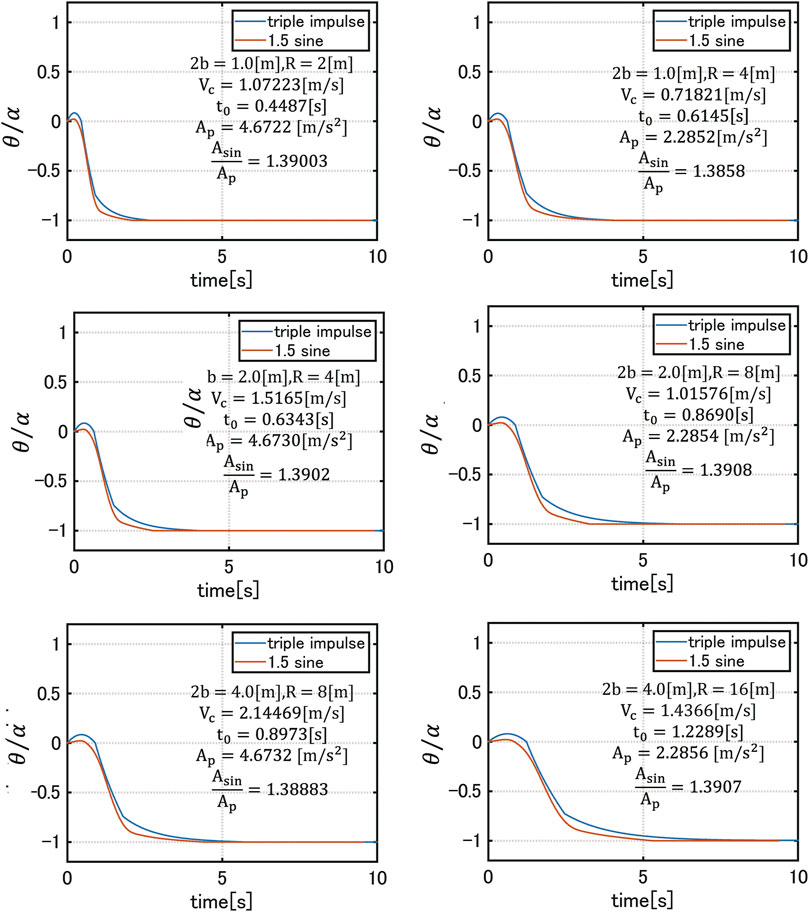
FIGURE 10. Comparison of time-history responses
Comparison of Overturning Limit Acceleration Amplitude and Overturning Limit Velocity Amplitude
Figure 11 shows the comparison of the overturning limit acceleration amplitude
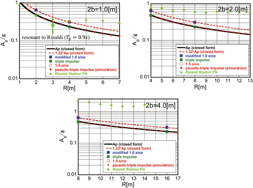
FIGURE 11. Comparison of overturning limit acceleration amplitude
In Figure 11, the plot of the overturning limit acceleration of Rinaldi Station FN shown in Figure 1 is also presented. Only the amplitude modulation was conducted. Since the resonant phenomenon can be found only around
Figure 12 presents the comparison of the overturning limit velocity amplitude
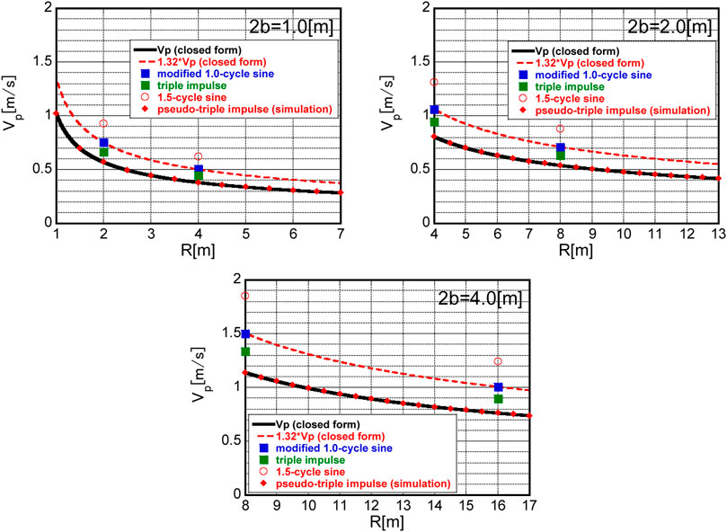
FIGURE 12. Comparison of overturning limit velocity amplitude
It should be remarked that, since the input periods of the 1.0-cycle and 1.5-cycle sinusoidal waves used in Figures 11, 12 are based on Eq. 23 for the pseudo-triple impulse, their criticality is not necessarily clear. If true critical periods of the 1.0-cycle and 1.5-cycle sinusoidal waves are sought and used, the corresponding limit input levels may become slightly smaller ones.
Additional Theoretical Investigation for Triple Impulse
In this section, a closed-form overturning velocity limit for the triple impulse is derived. It is assumed here again that the second impulse acts just after the impact of the rigid block on the floor. In this case, the timing of the third impulse is prescribed.
The equation of free-vibration motion of the rigid block after the second impulse can be described by
Using the approximation
The general solution of Eq. 9 can be expressed by
Using the rotation condition
The rotation during the free vibration after the second impulse can then be expressed by
Here,
From these conditions, the rotation
Let
Therefore,
The rotation
Let
From the energy conservation law, the following relation holds.
Substitution of the overturning condition
Substitution of all the derived quantities into Eq. 23 and solution of the resulting equation for the velocity lead to the final form of the overturning limit velocity
Figure13 shows the overturning limit velocity
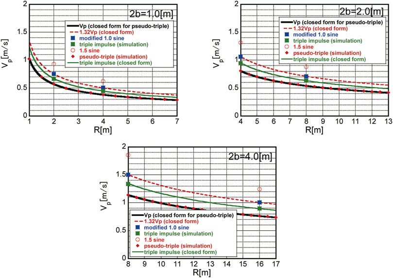
FIGURE 13. Comparison of overturning limit velocity amplitude
Conclusion
An approximate closed-form limit has been derived on the input level of the pseudo-triple impulse as a representative of the principal part of a near-fault ground motion for the overturning of a rigid block. The conclusions may be summarized as follows.
1) As in the double impulse case, the rocking vibration of a rigid block can be formulated by incorporating the conservation law of angular momentum and the conservation law of mechanical energy. The conservation law of angular momentum enables the determination of the initial rotational velocity just after the first impulse and the rotational velocity changes at the impact of the rigid block on the floor and the impact due to the second impulse. On the other hand, the conservation law of energy enables the determination of the maximum rotational angle after the first impulse and that after the second impulse. These maximum rotational angles are required for the computation of the overturning limit. These two conservation laws are quite effective and enables us to avoid the complicated non-linear time-history response analysis.
2) The critical timing of the second impulse after the action of the first impulse has been characterized by the time of impact of the rigid block on the floor. The action of the second impulse just after the impact corresponds to the critical timing as in the case of the double impulse. Although, in most cases under the triple impulse, the third impulse acts before the overturning occurs, the neglect of the third impulse leads to a closed-form expression of the overturning limit for the pseudo-triple impulse where the third impulse in the triple impulse is disregarded.
3) By introducing the condition that the attainment of the maximum rotational angle
4) The limit input velocity for the pseudo-triple impulse is slightly larger than the limit for the double impulse derived in Nabeshima et al. (2016). This finding was enabled through the closed-form expression of the limit input velocity.
5) Numerical examples including the comparison with the numerical simulation results by the Runge-Kutta method demonstrated the accuracy and reliability of the proposed method. However, as for the comparison of the response to the pseudo-triple impulse with that to the equivalent modified 1.0-cycle sinusoidal wave, a magnification coefficient (about 1.31–1.32 in this case) should be introduced for guaranteeing the correspondence of the responses to the pseudo-triple impulse and to the equivalent modified 1.0-cycle sinusoidal wave.
6) It was demonstrated that, when the third impulse is taken into account, the limit input velocity for the overturning of the rigid block becomes larger. This is because the third impulse may prevent the overturning of the rigid block by giving an impact toward the inverse direction of the vibration of the rigid block. In this case, a magnification coefficient (about 1.38–1.39 in the present case) should be introduced for guaranteeing the correspondence of the responses to the triple impulse and to the equivalent 1.5-cycle sinusoidal wave. The closed-form overturning limit velocity for the triple impulse was also derived by using the conservation law of angular momentum and energy.
7) Since the overturning limit is sensitive to the input frequency (period) of the related sinusoidal waves, the comparisons of the overturning limits in terms of
The realization of the critical case (combination of the critical impulse timing and the critical velocity amplitude) is very rare and it may be difficult to simulate this critical case using actual ground motions without amplitude modulation. The principal purpose of this paper is to derive the explicit overturning limit even for a simple input. The detailed application of the present result to actual ground motions will be investigated in the future.
Data Availability Statement
The original contributions presented in the study are included in the article/Supplementary Material, further inquiries can be directed to the corresponding author.
Author Contributions
SH formulated the problem, conducted the computation, and wrote the paper. KN conducted the computation and discussed the results. IT supervised the research and wrote the paper.
Funding
Part of the present work is supported by the Grant-in-Aid for Scientific Research (KAKENHI) of Japan Society for the Promotion of Science (No.18H01584). This support is greatly appreciated.
Conflict of Interest
The authors declare that the research was conducted in the absence of any commercial or financial relationships that could be construed as a potential conflict of interest.
Publisher’s Note
All claims expressed in this article are solely those of the authors and do not necessarily represent those of their affiliated organizations, or those of the publisher, the editors and the reviewers. Any product that may be evaluated in this article, or claim that may be made by its manufacturer, is not guaranteed or endorsed by the publisher.
References
Bray, J. D., and Rodriguez-Marek, A. (2004). Characterization of Forward-Directivity Ground Motions in the Near-Fault Region. Soil Dyn. Earthquake Eng. 24 (11), 815–828. doi:10.1016/j.soildyn.2004.05.001
Casapulla, C., Jossa, P., and Maione, A. (2010). Rocking Motion of a Masonry Rigid Block under Seismic Actions: a New Strategy Based on the Progressive Correction of the Resonance Response. Ingegneria Sismica 27 (4), 35–48.
Casapulla, C., and Maione, A. (2017). Free Damped Vibrations of Rocking Rigid Blocks as Uniformly Accelerated Motions. Int. J. Str. Stab. Dyn. 17, 1750058. doi:10.1142/S0219455417500584
Casapulla, C. (2015). On the Resonance Conditions of Rigid Rocking Blocks. Int. J. Eng. Tech. 7 (2), 760–771.
Champion, C., and Liel, A. (2012). The Effect of Near-Fault Directivity on Building Seismic Collapse Risk. Earthquake Engng Struct. Dyn. 41 (10), 1391–1409. doi:10.1002/eqe.1188
DeJong, M. J. (2012). Amplification of Rocking Due to Horizontal Ground Motion. Earthquake Spectra 28 (4), 1405–1421. doi:10.1193/1.4000085
Dimitrakopoulos, E. G., and DeJong, M. J. (2012a). Overturning of Retrofitted Rocking Structures under Pulse-type Excitations. J. Eng. Mech. 138 (8), 963–972. doi:10.1061/(asce)em.1943-7889.0000410
Dimitrakopoulos, E. G., and DeJong, M. J. (2012b). Revisiting the Rocking Block: Closed-form Solutions and Similarity Laws. Proc. R. Soc. A. 468, 2294–2318. doi:10.1098/rspa.2012.0026
ElGawady, M. A., Ma, Q., Butterworth, J. W., and Ingham, J. (2011). Effects of Interface Material on the Performance of Free Rocking Blocks. Earthquake Engng. Struct. Dyn. 40, 375–392. doi:10.1002/eqe.1025
Gerami, M., and Sivandi-Pour, A. (2014). Performance-based Seismic Rehabilitation of Existing Steel Eccentric Braced Buildings in Near Fault Ground Motions. Struct. Des. Tall Spec. Build. 23 (12), 881–896. doi:10.1002/tal.1088
Hall, J. F., Heaton, T. H., Halling, M. W., and Wald, D. J. (1995). Near-source Ground Motion and its Effects on Flexible Buildings. Earthquake Spectra 11 (4), 569–605. doi:10.1193/1.1585828
Hayden, C. P., Bray, J. D., and Abrahamson, N. A. (2014). Selection of Near-Fault Pulse Motions. J. Geotechnical Geoenvironmental Eng. ASCE 140 (7). doi:10.1061/(asce)gt.1943-5606.0001129
Hogan, S. J. (1989). On the Dynamics of Rigid-Block Motion under Harmonic Forcing. Proc. R. Soc. Lond. A. 425, 441–476. doi:10.1098/rspa.1989.0114
Housner, G. W. (1963). The Behavior of Inverted Pendulum Structures during Earthquakes. Bull. Seismol. Soc. Am. 53 (2), 404–417. doi:10.1785/bssa0530020403
Ishiyama, Y. (1982). Motions of Rigid Bodies and Criteria for Overturning by Earthquake Excitations. Earthquake Engng. Struct. Dyn. 10, 635–650. doi:10.1002/eqe.4290100502
Kalkan, E., and Kunnath, S. K. (2006). Effects of Fling Step and Forward Directivity on Seismic Response of Buildings. Earthquake Spectra 22 (2), 367–390. doi:10.1193/1.2192560
Khaloo, A. R., Khosravi, H., and Jamnani, H. H. (2015). Nonlinear Interstory Drift Contours for Idealized Forward Directivity Pulses Using "Modified Fish-Bone" Models. Adv. Struct. Eng. 18 (5), 603–627. doi:10.1260/1369-4332.18.5.603
Khansefid, A., Bakhshi, A., and Ansari, A. (2019). Development of Declustered Processed Earthquake Accelerogram Database for the Iranian Plateau: Including Near-Field Record Categorization. J. Seismol 23, 869–888. doi:10.1007/s10950-019-09839-w
Khansefid, A. (2020). Pulse-like Ground Motions: Statistical Characteristics, and GMPE Development for the Iranian Plateau. Soil Dyn. Earthquake Eng. 134, 106164. doi:10.1016/j.soildyn.2020.106164
Kohrangi, M., Vamvatsikos, D., and Bazzurro, P. (2018). Pulse-like versus Non-pulse-like Ground Motion Records: Spectral Shape Comparisons and Record Selection Strategies. Earthquake Engng Struct. Dyn. 48 (1), 46–64. doi:10.1002/eqe.3122
Kojima, K., and Takewaki, I. (2016). Closed-form Dynamic Stability Criterion for Elastic-Plastic Structures under Near-Fault Ground Motions. Front. Built Environ. 2, 6. doi:10.3389/fbuil.2016.00006
Kojima, K., and Takewaki, I. (2015a). Critical Earthquake Response of Elastic-Plastic Structures under Near-Fault Ground Motions (Part 1: Fling-step Input). Front. Built Environ. 1, 12. doi:10.3389/fbuil.2015.00012
Kojima, K., and Takewaki, I. (2015b). Critical Earthquake Response of Elastic-Plastic Structures under Near-Fault Ground Motions (Part 2: Forward-Directivity Input). Front. Built Environ. 1, 13. doi:10.3389/fbuil.2015.00013
Makris, N., and Kampas, G. (2016). Size versus Slenderness: Two Competing Parameters in the Seismic Stability of Free-Standing Rocking Columns. Bull. Seismol. Soc. Am. 106 (1), 104–122. doi:10.1785/0120150138
Makris, N., and Black, C. J. (2004). Dimensional Analysis of Rigid-Plastic and Elastoplastic Structures under Pulse-type Excitations. J. Eng. Mech. 130, 1006–1018. doi:10.1061/(asce)0733-9399(2004)130:9(1006)
Mavroeidis, G. P., Dong, G., and Papageorgiou, A. S. (2004). Near-fault Ground Motions, and the Response of Elastic and Inelastic single-degree-of-Freedom(SDOF) Systems. Earthquake Engng. Struct. Dyn. 33, 1023–1049. doi:10.1002/eqe.391
Mavroeidis, G. P., and Papageorgiou, A. S. (2003). A Mathematical Representation of Near-Fault Ground Motions. Bull. Seismological Soc. America 93 (3), 1099–1131. doi:10.1785/0120020100
Mukhopadhyay, S., and Gupta, V. K. (2013a). Directivity Pulses in Near-Fault Ground Motions-I: Identification, Extraction and Modeling. Soil Dyn. Earthquake Eng. 50, 1–15. doi:10.1016/j.soildyn.2013.02.017
Mukhopadhyay, S., and Gupta, V. K. (2013b). Directivity Pulses in Near-Fault Ground Motions-II: Estimation of Pulse Parameters. Soil Dyn. Earthquake Eng. 50, 38–52. doi:10.1016/j.soildyn.2013.02.019
Nabeshima, K., Taniguchi, R., Kojima, K., and Takewaki, I. (2016). Closed-form Overturning Limit of Rigid Block under Critical Near-Fault Ground Motions. Front. Built Environ. 2, 9. doi:10.3389/fbuil.2016.00009
Pompei, A., Scalia, A., and Sumbatyan, M. A. (1998). Dynamics of Rigid Block Due to Horizontal Ground Motion. J. Eng. Mech. 124 (7), 713–717. doi:10.1061/(asce)0733-9399(1998)124:7(713)
Prieto, F., Lourenço, P. B., and Oliveira, C. S. (2004). Impulsive Dirac-delta Forces in the Rocking Motion. Earthquake Engng. Struct. Dyn. 33, 839–857. doi:10.1002/eqe.381
Rupakhety, R., and Sigbjörnsson, R. (2011). Can Simple Pulses Adequately Represent Near-Fault Ground Motions? J. Earthquake Eng. 15, 1260–1272. doi:10.1080/13632469.2011.565863
Sasani, M., and Bertero, V. V. (2000). Proc. Of the Twelfth World Conf. Auckland, New Zealand: on Earthquake Eng.Importance of Severe Pulse-type Ground Motions in Performance-Based Engineering: Historical and Critical Review
Shenton III, H. W., and Jones, N. P. (1991). Base Excitation of Rigid Bodies. I: Formulation. J. Eng. Mech. 117 (10), 2286–2306. doi:10.1061/(asce)0733-9399(1991)117:10(2286)
Spanos, P. D., and Koh, A. S. (1984). Rocking of Rigid Blocks Due to Harmonic Shaking. J. Eng. Mech. 110 (11), 1627–1642. doi:10.1061/(asce)0733-9399(1984)110:11(1627)
Takewaki, I., and Kojima, K. (2021). An Impulse and Earthquake Energy Balance Approach in Nonlinear Structural Dynamics. Boca Raton, FL: CRC Press.
Taniguchi, R., Kojima, K., and Takewaki, I. (2016). Critical Response of 2DOF Elastic-Plastic Building Structures under Double Impulse as Substitute of Near-Fault Ground Motion. Front. Built Environ. 2, 2. doi:10.3389/fbuil.2016.00002
Taniguchi, R., Nabeshima, K., Kojima, K., and Takewaki, I. (2017). Closed-form Rocking Vibration of Rigid Block under Critical and Non-critical Double Impulse. Int. J. Earthq. Impact Eng. 2 (1), 32–45. doi:10.1504/ijeie.2017.083708
Vafaei, D., and Eskandari, R. (2015). Seismic Response of Mega Buckling-Restrained Braces Subjected to Fling-step and Forward-Directivity Near-Fault Ground Motions. Struct. Des. Tall Spec. Build. 24, 672–686. doi:10.1002/tal.1205
Xu, Z., Agrawal, A. K., He, W.-L., and Tan, P. (2007). Performance of Passive Energy Dissipation Systems during Near-Field Ground Motion Type Pulses. Eng. Structures 29, 224–236. doi:10.1016/j.engstruct.2006.04.020
Yang, D., and Zhou, J. (2014). A Stochastic Model and Synthesis for Near-Fault Impulsive Ground Motions. Earthquake Engng Struct. Dyn. 44, 243–264. doi:10.1002/eqe.2468
Yilmaz, C., Gharib, M., and Hurmuzlu, Y. (2009). Solving Frictionless Rocking Block Problem with Multiple Impacts. Proc. R. Soc. A. 465, 3323–3339. doi:10.1098/rspa.2009.0273
Yim, C.-S., Chopra, A. K., and Penzien, J. (1980). Rocking Response of Rigid Blocks to Earthquakes. Earthquake Engng. Struct. Dyn. 8 (6), 565–587. doi:10.1002/eqe.4290080606
Zhai, C., Chang, Z., Li, S., Chen, Z., and Xie, L. (2013). Quantitative Identification of Near-Fault Pulse-like Ground Motions Based on Energy. Bull. Seismological Soc. America 103 (5), 2591–2603. doi:10.1785/0120120320
Keywords: earthquake response, near-fault ground motion, forward-directivity input, triple impulse, rigid block, rocking, critical response, overturning
Citation: Homma S, Nabeshima K and Takewaki I (2021) Explicit Overturning Limit of Rigid Block Using Triple and Pseudo-Triple Impulses Under Critical Near-Fault Ground Motions. Front. Built Environ. 7:731670. doi: 10.3389/fbuil.2021.731670
Received: 27 June 2021; Accepted: 10 August 2021;
Published: 25 August 2021.
Edited by:
Ehsan Noroozinejad Farsangi, Graduate University of Advanced Technology, IranReviewed by:
Abbas Sivandi-Pour, Graduate University of Advanced Technology, IranAli Khansefid, K. N. Toosi University of Technology, Iran
Copyright © 2021 Homma, Nabeshima and Takewaki. This is an open-access article distributed under the terms of the Creative Commons Attribution License (CC BY). The use, distribution or reproduction in other forums is permitted, provided the original author(s) and the copyright owner(s) are credited and that the original publication in this journal is cited, in accordance with accepted academic practice. No use, distribution or reproduction is permitted which does not comply with these terms.
*Correspondence: Izuru Takewaki, dGFrZXdha2lAYXJjaGkua3lvdG8tdS5hYy5qcA==