- 1School of Mechanics and Civil Engineering, China University of Mining and Technology, Beijing, China
- 2State Key Laboratory of Coal Resources and Safe Mining, China University of Mining and Technology, Beijing, China
Reliable estimation of fracture network length and morphology in hydrofracturing is crucial for controlling and optimizing fracturing effects. Hydraulic fracture propagation will be affected by a variety of factors to produce deflection, resulting in different fracture network morphology. To study the spatial deflection behaviours of multiple parallel hydraulic fractures, three-dimensional engineering-scale numerical model for multistage fracturing is established to study the induced shear stress disturbance and unstable spatial propagation behavior of hydraulic fractures under different perforation cluster spacing. In the model, the thermal diffusion, fluid flow and deformation of rock between the rock matrix and fluid in pores and fractures are considered to describe the thermal-hydro-mechanical coupling. In this study, the results show that the thermal effect between fracturing fluid and rock matrix is an important factor affecting fracture propagation, and thermal effects can increase induced shear stress area and promote fracture propagation. The induced shear stress disturbance caused by fracture propagation is superimposed in multiple fractures, resulting in stress shadow effect and spatial deflection of parallel fractures. The stress shadow areas and the spatial deflection of parallel hydraulic fractures will increase with the decrease of multiple perforation cluster spacing.
Introduction
Reliable estimation of fracture network length and morphology in hydrofracturing is crucial for controlling and optimizing fracturing effects. Hydraulic fracture propagation will be affected by various factors, resulting in different fracture network morphology, including the coupling of multiple physical fields in the formation. Multiple physical fields coupling in formation should be considered to explain the fracture propagation behaviours. The linear thermal-pore-elastic effects and a combination of fine and coarse meshes have been used to model thermal-hydro-mechanical (THM) coupling processes in fractures (Kohl et al., 1995; Ghassemi and Zhou, 2011; Zhao et al., 2015). Based on the mixed finite element-finite volume method, a three-dimensional (3D) hydrofracturing model embedded in the natural fractures was proposed considering thermal effects (Li et al., 2016).
In addition to the coupling of multiple physical fields, which is an internal factor affecting the internal properties of rock mass, the interaction of multiple fractures in fracture propagation also affects fracture propagation. In the process of hydraulic fracture propagation, 3D fractures are accompanied by spatial deflection and compression between fractures, resulting in unstable fracture propagation (Wong et al., 2013; Manriquez et al., 2017). The different perforation cluster spacing of multistage fracturing will cause different degrees of of hydraulic fractures spatial deflection, and the unstable propagation of fractures will affect control and design of final fracture network (Zhang and Jeffrey, 2012; Bažant et al., 2014). In the process of multi-fracture propagation, the induced stress field around the fracture will superposition and reduce to produce stress shadow effect. The spatial deflection of hydraulic fractures and the evolution of stress fields under different initial perforation forms become important factors affecting fracture network morphology and fracturing effects (Yoon et al., 2015; He et al., 2017; Sobhaniaragh et al., 2018; Gutierrez et al., 2019). By using numerical methods (such as finite element method, displacement discontinuity method and boundary element method) and models, the interaction of fracture network and stress shadow effect are quantitatively analysed, and the mechanisms of fracture initiation, propagation, and disturbance are investigated (Kresse et al., 2013; Paluszny et al., 2013; Taghichian et al., 2014; Kumar and Ghassemi, 2016). Besides, some high-performance mesh optimization models have been developed and applied (Wang et al., 2021).
In this study, an engineering-scale 3D numerical model of multistage hydrofracturing of horizontal well is developed for the study of spatial fracture deflection and induced shear stress disturbance considering thermal effects, and the typical perforation cluster spacing are set to study the influences of cluster spacing on spatial fracture deflection and stress shadows.
Numerical Method and Model for Hydrofracturing Considering Thermal Effects
Governing Equations Considering Thermal Effects
In this study, the physical fields involved in the fracturing process of reservoir rock include the temperature field, fluid field, and solid field (Wang et al., 2019; Wang, 2020). The matrix deformation governing equation of reservoir rock is as follow:
where L is the differential operator,
The following Eqs. 2, 3 are the governing equations of rock matrix seepage and fluid flow in fractures, respectively:
where
The governing equation of thermal effects between the rock matrix and fluid in pores and fractures is as follows:
where
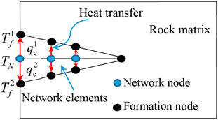
The differential governing Eqs. 1–3 of solid deformation of the rock matrix, fluid flow in pores and fractures, and thermal effects are discretized using the conventional finite element method. The form of heat transfer between element nodes is shown in Figure 1, and the temperature and heat flux at the nodes are as follows:
where
where
Three-Dimensional Numerical Model of Multistage Hydrofracturing Under Different Cluster Spacing
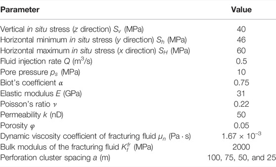
The engineering-scale 3D model of multistage hydrofracturing of horizontal well with multiple perforation clusters in deep tight rock is established, as shown in Figure 2. There are five perforation cluster locations, sequentially numbered from 1 to 5. The basic physical parameters and perforation cluster spacing settings of the model are shown in Table 1. According to the different initiation sequences of perforation clusters, the fracturing scheme can be divided into the sequential (fractures are fractured in the order of 1→2→3→4→5), simultaneous (fractures are fractured simultaneously), and alternate fracturing (fractures are fractured in the order of 1→3→2→5→4 (Wang, 2020), and the model is analyzed by finite element-discrete element methods in program package ELFEN (Rockfield Software Ltd., 2016). In this study, the three-dimensional deflection and induced shear stress evolution of alternate fracturing with different perforation cluster spacing are analyzed.
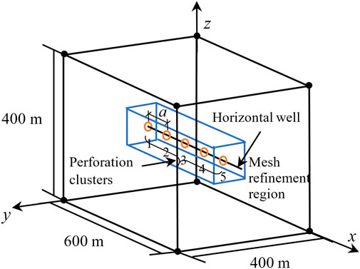
FIGURE 2. Initial geometric engineering-scale 3D model of multistage hydrofracturing of horizontal well with five perforation clusters.
Results and Analysis
Thermal Effects and Spatial Deflection of Parallel Hydraulic Fractures
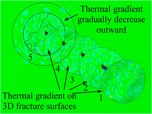
Figure 3 shows the thermal gradient on the 3D fracture surfaces and surrounding rock. The value of thermal gradient can represent temperature difference and thermal diffusion trend. It can be seen that there is a significant temperature gradient at the fracture surface due to the temperature difference, which makes the temperature domain rapidly diffuse. The temperature gradient of the rock mass from the fracture area to the periphery gradually decreases until the far-field temperature gradient disappears.
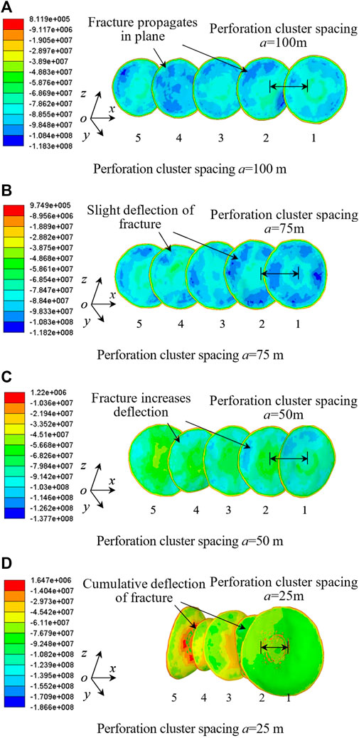
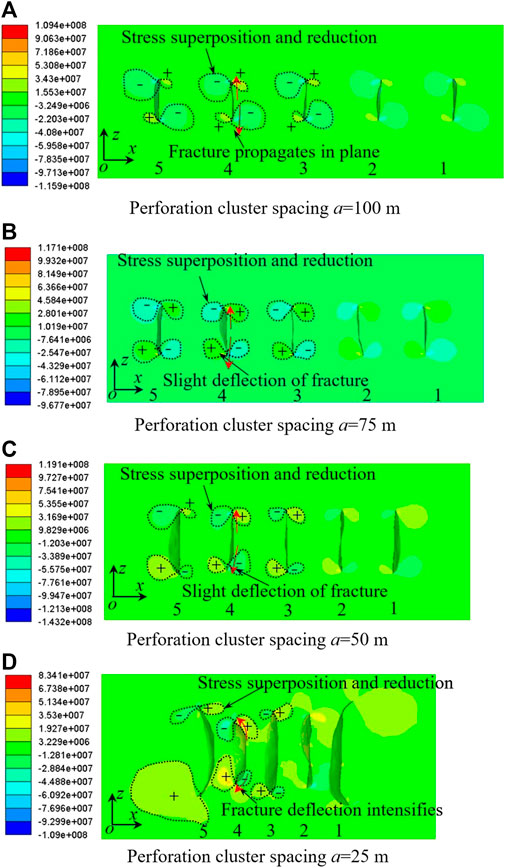
Figure 4 shows the final fracture morphology and stress field results under different perforation cluster spacing in alternate fracturing. When the cluster spacing is large, the fractures are nearly parallel and stable. With the decrease of the perforation cluster spacing, the mutual interference between fractures gradually increases, and the deflection intensifies. The spacing of perforation clusters is an important factor affecting the spatial deflection behavior of spatial fractures.
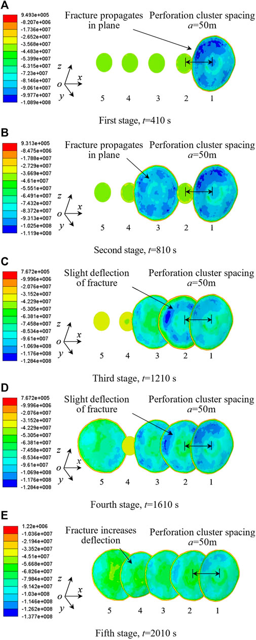
Figure 5 shows the results of fracture propagation at each stage of alternate fracturing. The first fracture propagates in space close to the plane because there is no interference from other fractures. The fracture 3 propagates in space close to the plane due to the spacing between fracture 1 and fracture 3 is 100 m (This is equivalent to increasing the spacing between sequentially activated fractures). The fracture 2 is disturbed by fractures 1 and 3, and the deflection is intensified. Similarly, fracture 4 propagates after fracture 5 has completed fracturing and is deflected by disturbance from fracture 3 and fracture 5.
Shear Stress Disturbance Induced by Multistage Hydrofracturing Under Different Cluster Spacing
A comparison of induced shear stress disturbance under thermal-hydraulic (HM) coupling and THM coupling is shown in Figure 6. The upper left side of the fracture is positive shear stress and the right side is negative shear stress. At the same time, the shear stress is negative at lower left of the fracture, andshear stress is positive at the lower right of the fracture. By comparing Figures 6A,B, it is found that the induced shear stress field area around the fracture is larger when the thermal effect is considered, and the shear stress disturbance caused by the reduction of induced shear stress superposition is stronger. The degree of fracture propagation and spatial deflection also increase. Therefore, thermal diffusion has a great influence on the induced shear stress field disturbance around the fracture, which needs to be considered.
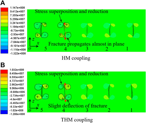
FIGURE 6. Disturbance of shear stress (Pa) in sequential fracturing for a cluster spacing of 100 m (“+” represents positive shear stress, and “−” represents negative shear stress).
Figure 7 shows the shear stress disturbance of alternate fracturing at different spacing of perforation clusters. At 100 m of perforation cluster spacing, the induced shear stress field around the fractures are slightly superimposed and reduced, and the fracture propagation is less affected by stress shadow effect. With the decrease of the spacing between perforating clusters, the superposition and disturbance of stress field between fractures gradually intensify. At 50 m of perforation cluster spacing, the positive and negative shear stress areas near the fractures superimpose obviously, resulting in the shear stress field on the right side of fracture 4 reduces obviously, and the fracture deflected to the left side of the larger shear stress field. At 25 m of perforation cluster spacing, the induced shear stress field around the fractures are superimposed and reduced seriously, resulting in the shear stress field on the right side of fracture 4 reduces obviously, and the deflection degree to the larger shear stress area on the left side becomes larger.
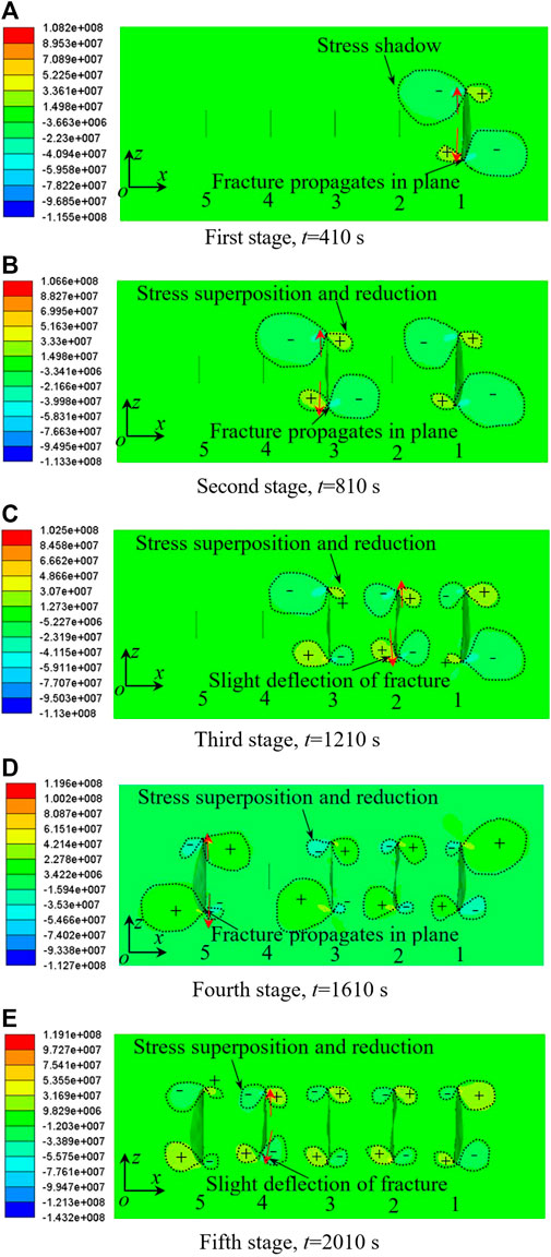
Figure 8 shows the shear stress disturbance of alternate fracturing. In the first stage, the stress around the first fracture is almost symmetrical and the fracture propagates in a plane direction. In the second stage, fracture 3 begins to propagate, and since the two fractures are separated by uninitiated fracture 2, the stress shadow area around fracture 1 does not cover the shear stress area caused by fracture 3, so fracture 3 is not affected by stress shadow and propagates in plane. In the third stage, the shear stress field around fracture 2 is superimposed and reduced with the stress shadow around fracture 1 and fracture 3, causing fracture 2 to propagate and deflect towards the larger stress area. Similarly, in the fifth stage, the induced shear stress field around fracture 4 is superimposed and reduced with the stress shadow around fracture 3 and fracture 5, and the fracture deflection is intensified.
Conclusion
The conclusions of this study can be summarized as follows:
1) Fracture propagation results under different spacing of perforation clusters show that the decrease of the spacing of multiple perforation clusters in horizontal wells will aggravate the mutual interference between parallel fractures and lead to the increase of fractures spatial deflection. The spacing of perforation clusters is an important factor affecting spatial deflection of spatial hydraulic fractures. Alternate fracturing can increase the spacing between sequentially activated fractures and reduce the deflection of hydraulic fractures.
2) As the spacing of perforation clusters decreases, the superposition area of shear stress field will increase, and the shear stress disturbance will become stronger, thus increasing the mutual interference between parallel fractures. In alternate fracturing, as fractures are activated alternately, the superposition and reduction of shear stress fields around fractures occur, decreasing the mutual interference between parallel fractures.
3) The thermal effect between fracturing fluid and rock matrix is an important factor affecting fracture propagation, and thermal effect may promote fracture propagation, and ignoring the thermal effects will underestimate the propagation of fracture networks. To investigate the mechanisms of thermal effects on stress variation, some micro-scale modelling and analysis need to be studied in the next work.
Data Availability Statement
The original contributions presented in the study are included in the article/Supplementary Material; further inquiries can be directed to the corresponding author.
Author Contributions
YW: Conceptualization, methodology, resources, writing—reviewing and editing, supervision, project administration, and funding acquisition. NL: Methodology, software, formal analysis, investigation, data curation, writing—original draft preparation, and visualization. YC: Formal analysis, data curation, and writing—original draft preparation. XL: Software, formal analysis, and data curation.
Funding
The authors gratefully acknowledge the financial support from the National Natural Science Foundation of China (grants 41877275 and 51608301); Beijing Natural Science Foundation (grant L212016); Yue Qi Young Scholar Project Foundation of China University of Mining and Technology, Beijing (grant 2019QN14); Fundamental Research Funds for the Central Universities, Ministry of Education of China (grant 2019QL02); Teaching Reform and Research Projects of Undergraduate Education of China University of Mining and Technology, Beijing (grants J210613, J200709, and J190701); and Open Fund of Tianjin Key Lab of Soft Soil Characteristics and Engineering Environment (grant 2017SCEEKL003).
Conflict of Interest
The authors declare that the research was conducted in the absence of any commercial or financial relationships that could be construed as a potential conflict of interest.
Publisher’s Note
All claims expressed in this article are solely those of the authors and do not necessarily represent those of their affiliated organizations, or those of the publisher, the editors, and the reviewers. Any product that may be evaluated in this article, or claim that may be made by its manufacturer, is not guaranteed or endorsed by the publisher.
References
Bažant, Z. P., Salviato, M., Chau, V. T., Viswanathan, H., and Zubelewicz, A. (2014). Why Fracking Works. J. Appl. Mech. 81 (10), 1–10. doi:10.1115/1.4028192
Ghassemi, A., and Zhou, X. (2011). A Three-Dimensional Thermo-Poroelastic Model for Fracture Response to Injection/extraction in Enhanced Geothermal Systems. Geothermics 40, 39–49. doi:10.1016/j.geothermics.2010.12.001
Gutierrez Escobar, R., Mejia Sanchez, E. C., Roehl, D., and Romanel, C. (2019). XFEM Modeling of Stress Shadowing in Multiple Hydraulic Fractures in Multi-Layered Formations. J. Nat. Gas Sci. Eng. 70, 1–15. doi:10.1016/j.jngse.2019.102950
He, Q., Suorineni, F. T., Ma, T., and Oh, J. (2017). Effect of Discontinuity Stress Shadows on Hydraulic Fracture Re-orientation. Int. J. Rock Mech. Min. Sci. 91, 179–194. doi:10.1016/j.ijrmms.2016.11.021
Kohl, T., Evansi, K. F., Hopkirk, R. J., and Rybach, L. (1995). Coupled Hydraulic, Thermal and Mechanical Considerations for the Simulation of Hot Dry Rock Reservoirs. Geothermics 24 (3), 345–359. doi:10.1016/0375-6505(95)00013-G
Kresse, O., Weng, X., Gu, H., and Wu, R. (2013). Numerical Modeling of Hydraulic Fractures Interaction in Complex Naturally Fractured Formations. Rock Mech. Rock Eng. 46 (3), 555–568. doi:10.1007/s00603-012-0359-2
Kumar, D., and Ghassemi, A. (2016). A Three-Dimensional Analysis of Simultaneous and Sequential Fracturing of Horizontal Wells. J. Petroleum Sci. Eng. 146, 1006–1025. doi:10.1016/j.petrol.2016.07.001
Li, S., Li, X., and Zhang, D. (2016). A Fully Coupled Thermo-Hydro-Mechanical, Three-Dimensional Model for Hydraulic Stimulation Treatments. J. Nat. Gas Sci. Eng. 34, 64–84. doi:10.1016/j.jngse.2016.06.046
Lopez Manriquez, A., Sepehrnoori, K., and Cortes, A. (2017). A Novel Approach to Quantify Reservoir Pressure along the Horizontal Section and to Optimize Multistage Treatments and Spacing between Hydraulic Fractures. J. Petroleum Sci. Eng. 149, 579–590. doi:10.1016/j.petrol.2016.10.068
Paluszny, A., Tang, X. H., and Zimmerman, R. W. (2013). Fracture and Impulse Based Finite-Discrete Element Modeling of Fragmentation. Comput. Mech. 52 (5), 1071–1084. doi:10.1007/s00466-013-0864-5
Sobhaniaragh, B., Mansur, W. J., and Peters, F. C. (2018). The Role of Stress Interference in Hydraulic Fracturing of Horizontal Wells. Int. J. Rock Mech. Min. Sci. 106, 153–164. doi:10.1016/j.ijrmms.2018.04.024
Taghichian, A., Zaman, M., and Devegowda, D. (2014). Stress Shadow Size and Aperture of Hydraulic Fractures in Unconventional Shales. J. Petroleum Sci. Eng. 124, 209–221. doi:10.1016/j.petrol.2014.09.034
Wang, Y. (2021). Adaptive Finite Element-Discrete Element Analysis for Stratal Movement and Microseismic Behaviors Induced by Multistage Propagation of Three-Dimensional Multiple Hydraulic Fractures. Ec 38 (6), 2781–2809. doi:10.1108/EC-07-2020-0379
Wang, Y., Ju, Y., Chen, J., and Song, J. (2019). Adaptive Finite Element-Discrete Element Analysis for the Multistage Supercritical CO2 Fracturing and Microseismic Modelling of Horizontal Wells in Tight Reservoirs Considering Pre-existing Fractures and Thermal-Hydro-Mechanical Coupling. J. Nat. Gas Sci. Eng. 61, 251–269. doi:10.1016/j.jngse.2018.11.022
Wang, Y., Liu, N., Zhang, X., Liu, X., and Wang, J. (2021). Influences on Unstable Hydraulic Fractures: Propagation of Adjacent Multiple Perforations and Bedded Interfaces in Multilayered Reservoir via FE-DE Model. Ec. doi:10.1108/EC-03-2021-0185
Wong, S.-W., Geilikman, M., and Xu, G. (2013). “Interaction of Multiple Hydraulic Fractures in Horizontal Wells,” in SPE Unconventional Gas Conference and Exhibition (Muscat, Sultanate of Oman: OnePetro). doi:10.2118/163982-MS
Yoon, J. S., Zimmermann, G., and Zang, A. (2015). Numerical Investigation on Stress Shadowing in Fluid Injection-Induced Fracture Propagation in Naturally Fractured Geothermal Reservoirs. Rock Mech. Rock Eng. 48 (4), 1439–1454. doi:10.1007/s00603-014-0695-5
Zhang, X., and Jeffrey, R. G. (2012). Fluid-driven Multiple Fracture Growth from a Permeable Bedding Plane Intersected by an Ascending Hydraulic Fracture. J. Geophys. Res. 117, a–n. doi:10.1029/2012JB009609
Keywords: spatial deflection of parallel hydraulic fractures, induced shear stress disturbance, thermal effects, multistage hydrofracturing, cluster spacing
Citation: Wang Y, Liu N, Cui Y and Liu X (2022) Spatial Deflection of Parallel Hydraulic Fractures and Induced Shear Stress Disturbance Under Different Perforation Cluster Spacing Considering Thermal Effects. Front. Built Environ. 8:885993. doi: 10.3389/fbuil.2022.885993
Received: 28 February 2022; Accepted: 29 April 2022;
Published: 02 September 2022.
Edited by:
Nikos D. Lagaros, National Technical University of Athens, GreeceReviewed by:
SeonHong Na, McMaster University, CanadaYunliang Tan, Shandong University of Science and Technology, China
Ali Taghichian, Institut für Gebirgsmechanik, Germany
Copyright © 2022 Wang, Liu, Cui and Liu. This is an open-access article distributed under the terms of the Creative Commons Attribution License (CC BY). The use, distribution or reproduction in other forums is permitted, provided the original author(s) and the copyright owner(s) are credited and that the original publication in this journal is cited, in accordance with accepted academic practice. No use, distribution or reproduction is permitted which does not comply with these terms.
*Correspondence: Yongliang Wang, d2FuZ3lsQGN1bXRiLmVkdS5jbg==
 Yongliang Wang
 Nana Liu1