 Mariano Angelo Zanini
 Flora Faleschini
 Carlo Pellegrino
- 1Department of Civil, Environmental, and Architectural Engineering, University of Padova, Padova, Italy
- 2Department of Industrial Engineering, University of Padova, Padova, Italy
The evaluation of the current prestress force represents often a challenging issue during the assessment of existing post-tensioned concrete (PTC) members. In this contribution, two case studies are presented to show the efficiency of some experimental methods applied both to laboratory beams and to an in-service PTC bridge. First, the outcomes of an experimental campaign carried out on three PTC beams with a straight post-tensioned, non-grouted tendon are discussed. For each beam, three-point bending tests (3PBTs) were carried out applying increasing load steps until failure and varying the prestress force; at each load step, non-destructive tests (NDTs) were performed, namely, dynamic free vibration and ultrasonic tests. The variation of non-destructive parameters was evaluated as a function of the prestress force and of the structural damage. The second case study deals with a 50-year-old PTC bridge with grouted ducts. In this case, other than evaluating the existing geometry, structural details, and material properties, the following NDTs were performed: endoscopies, tests based on stress release, i.e., both saw-cut and wire-cut tests, and lastly, X-ray diffractometries (XRDs). The results indicate the high potential of this latter technique, which resulted more reliable and less invasive than the previous ones.
1 Introduction
In the field of civil infrastructures, the proper management of stocks of existing bridges and other civil structures has become an extremely complex issue that involves technical, social, economic, and political considerations. In this context, several research projects were financed aimed at identifying the broadly recognized procedures and strategies that can be applied by public and private authorities for the management of infrastructural assets (COST345, 2004; SAMARIS, 2005; COST TU1404, 2014). However, while this issue is gaining increasing social attention with time, as a consequence of structural failure events that had a great media impact (Faleschini et al., 2018; Calvi et al., 2019), there is still the need for more research efforts on this topic. Indeed, the current practice on the performance assessment of bridges, and more generally infrastructures, suffers from several deficiencies, the most well known of that being based on visual observations of structural damage only, thus being limited on qualitative data (Zanini et al., 2017a; Quirk et al., 2018). In-depth investigations are instead needed when safety and serviceability are evaluated during structures service life, and for them, it is necessary to improve and/or establish reliable procedures and techniques to carefully assess the current health condition of structures. In the field of post-tensioned concrete (PTC) structures, this becomes even more fundamental because the variation of prestress force within the element is an additional parameter of uncertainty (Osborn et al., 2012), other than the effects of deterioration (Tu et al., 2019), variation of the external loads (Crespo-Minguillón and Casas 1997), time-dependent phenomena (Oh and Yang 2000) involving material properties variation (Badalassi et al., 2017), e.g., for concrete, creep and shrinkage, and steel relaxation, natural hazard occurrence (Zanini et al., 2017b), etc.
The knowledge of the residual prestress force in existing PTC bridges is considered one of the fundamental keys for understanding the actual health condition of the whole structure. Tendons represent in fact the main load-carrying elements in this type of structural elements. Different deterioration phenomena may accelerate the prestress loss, which are often linked to corrosion processes acting on the tendons. Other than the well-known carbonation and chloride-induced corrosion (Angst et al., 2020; Berto et al., 2020), the stress-corrosion cracking represents another harmful phenomenon because the interaction between tensile stresses acting on a tendon and the corrosion favors the speed of the reaction (Calabrese and Proverbio, 2020). Furthermore, hydrogen embrittlement is also considered one possible source for the deterioration of metals in general, and thus, hazardous for steel tendons (Aliofkhazraei et al., 2021). Additionally, it should be recalled that an insufficient design of the drainage system, poor material properties (low-strength concrete with many voids leading to high diffusion of carbon and chlorides in the material), mistakes during the construction process (e.g., for grouted ducts, the well-known problem of the partial injection of the ducts with mortar, its segregation and the availability of free water to come into contact with the tendons inside the duct), and lastly insufficient concrete covers, make the PTC bridges high-vulnerable structures. Brittle collapses of these kind of structures were recorded and described in the literature (Moravčík and Bujňáková, 2017; Anania et al., 2018), demonstrating that PTC bridges can suddenly fail due to the reduction of the load-carrying capacity provided by the sole tendons. Furthermore, if a strand fails, the expected redistribution of stresses to the others might not occur, especially when a large number of voids are present in the grout (Martin et al., 2001).
A substantial difference between design and current prestress force might lead to serviceability and safety impairments (Saiidi et al., 1994), linked to the increase of tensile stresses in concrete and to the arise of possible cracking phenomena, with consequent effects on the exposure of reinforcement, and lastly leading to potential structural failure. Several studies highlighted discrepancies when experimental residual prestress force has been compared with the theoretical one, as predicted applying different codes, for prestressed members that were extracted from structures in service for more than 25 years (Azizinamini et al., 1996; Bagge et al., 2017). Such deviations (typically underestimating prestress loss) might be significant even if most of the codes are generally conservative in the estimation of prestress losses (Garber et al., 2015), which occur within the first months after the element casting and that are relatively easy to be predicted. Hence, such higher losses are associated to the aforementioned phenomena linked to material degradation, long-term effects, construction defects, or structural damage, that may lead to a progressive deterioration of the prestressing level along the PTC member.
In this context, the recent Italian Guidelines for the Risk Classification and Management of Bridges (Ministry of Italian Infrastructure, 2020) have classified the PTC bridges as high-vulnerable structures, for which specific assessment is often necessary. One of the key parameters that need to be investigated properly is the prestress loss, which should be estimated for a sufficient number of tendons with instrumental techniques operated in situ. However, there is still an open question about which test method is more suitable to obtain a reliable evaluation of this measure.
This work aims to describe some new insights about estimating the prestress loss in PTC members, by providing an additional contribution to the state-of-the-art of the scientific literature devoted to identify the most proper investigation techniques to be implemented for the quantification of prestress losses in PRC elements based on recent authors experiences carried out both in laboratory and in-field tests. First, a review of the existing available methods proposed in the literature is presented, with the aim to give an overview of current methods that can be implemented singularly or in combination with each other for testing PTC members. Then, the results of a first series of experimental tests on PTC laboratory beams are discussed: beams have 6 m length and a straight post-tensioned tendon, and were subject to varying prestress forces and damage. Lastly, in situ tests on a 50-year PTC bridge with grouted ducts were carried out. In all the cases, complementary tests were executed, aiming to compare the different techniques and the obtained results, which are critically discussed.
2 Review on current experimental methods to evaluate the prestress loss
The direct access to prestressing tendons is often a hard task, especially for those grouted. Thus, the direct evaluation of the effective strain, and thus, stress acting on each strand inside a duct becomes impossible in the practice, unless a monitoring system is conceived since the design of the PTC element, which should be applied before concrete casting. Hence, a series of indirect experimental methods have been proposed in the past and are currently used in the practice by bridge inspectors and laboratories to evaluate the current stress acting on the tendons. Table 1 lists a comparison of the most common methods with the aim to help a reader to select the most proper testing method or a combination of test methods in relation to different specific conditions, aims of the experimental campaign, field conditions, etc., to achieve a specific goal when testing post-tensioned concrete members.
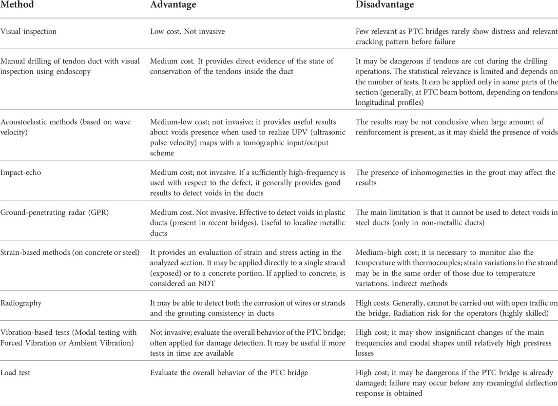
TABLE 1. Current experimental methods applied to PTC bridges for investigating prestress loss.
Other than these tests methods, some more recent experimental procedures were proposed and applied, worth mentioning that based on the X-ray diffraction technique (Morelli et al., 2021), which is an innovative NDT (non-destructive test) applied to PTC bridges. Such technique is commonly diffused in material science, as it is often used to analyze the microstructure of crystalline materials and it is based on the well-known Bragg equation:
which states that when the X-ray (with wavelength λ) is incident onto a crystal surface, its angle of incidence θ will reflect back with the same angle of scattering θ. When the path difference d (which is the distance between the planes of the crystalline lattice) is equal to the whole number n of wavelength λ, a constructive interference will occur. Such technique has been also applied to measure the so-called residual stresses in different applications, since more than 25 years (Prevéy, 1996). If the crystalline lattice is subject to a stress state, the interatomic distance modifies and this makes in turn a variation of the angle of scattering θ. Knowing the material composition (i.e., the steel type used for the strand realization) and its elastic properties (i.e., the elastic modulus E and the Poisson coefficient υ), it is possible to directly reconstruct the stress and strain state applied to the material. In Section 4 of the present work, more details on this technique are provided.
3 Laboratory tests on post-tensioned concrete beams with straight unbonded tendons
In this section, the results of an experimental campaign on three PTC beams with non-adherent (unbonded) strands, inserted in plastic ducts and placed at different eccentricity, are shown. The aim of this experimental campaign is to evaluate the potential of applying two NDT techniques, that is, a vibration-based and the UPV tomography, for damage assessment and the evaluation of prestress loss. The complete test report of this experimental campaign is provided in (Frizzarin, 2019).
3.1 Post-tensioned concrete beam geometry and material properties
All the beams are characterized by the same geometry and steel reinforcement but they differ from the position of the tendon, which have a different eccentricity and is non-grouted (see Figure 1). A rectangular cross section and a constant eccentricity e is selected to represent an idealized configuration of the PTC member and to remove potential secondary effects linked to the tendons layout, that can make understanding the results more difficult. The prestressing force was applied to each beam tensioning the strand with a hydraulic hollow jack, positioned at one end of the beam. The strand was locked with wedges, and at the interface between the hydraulic jack and the concrete surface 20 mm thick plates were positioned, in order to distribute the concentrated load on a 200 × 200 mm2 area. The amount of the prestress force is varied during the test through a hydraulic jack. Table 2 summarizes the main features of these beams.
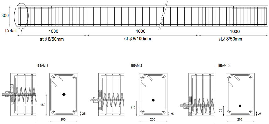
FIGURE 1. Laboratory PTC beams geometry and reinforcement arrangement.
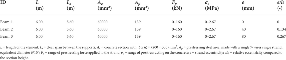
TABLE 2. Main features of the laboratory PTC beams.
Concerning material properties, the concrete cubic compressive strength is fc,cube = 64.7 ± 2.5 MPa, evaluated at the time of testing (about 55 days after concrete casting). For reinforcement, ordinary B450C steel was used, with experimental average yield strength fy = 512 MPa at about εy = 0.2%, tensile strength ft = 612 MPa, and average elongation = 9%. The prestressing steel was also experimentally tested, obtaining in average a nominal strength at 1% of total elongation fp(1)k = 1703 MPa, tensile strength fpt = 1925 MPa, and average elongation = 6.4%.
3.2 Test setup
PTC beams were subjected to 3PBTs, with a test program that includes a series of load–unload cycles up to failure. Between each loading cycle, NDTs were carried out, at different values of the prestress force (regulated by the hydraulic jack). Figure 2A shows the loading scheme: note that the vertical load application point is asymmetric. In the same figure, the instrumentation adopted is indicated. Other than the vertical load and the prestress force, the static parameters were continuously also acquired during the test : vertical displacements along the length of the element through five LVDTs (linear variable differential transducers) with a precision of ± 0.01 mm; concrete strains at relevant locations, adopting four couples of DD1s (distortion detectors) with ± 0.001 mm precision, placed closed to the top and bottom of the sections, to reconstruct the strain profile at each analyzed section.
FIGURE 2. Test setup and instrumentation disposition: (A) 3PBT test and (B) NDT1 test (A = accelerometers; H = instrumented hammer).
The NDTs applied in this experimental campaign are 1) dynamic free vibrations measurements and 2) ultrasonic tests. The first test method (NDT1) was carried out using 10 accelerometers, located at relevant positions of the element and an instrumented hammer that triggers the impulsive force. The acquisition system was a NI PXI-1042Q, which allowed to record the signals that were further analyzed in the frequency domain through frequency domain decomposition (FDD) to derive the modal parameter of interest. Figure 2B shows the locations of the accelerometers and those where the impulsive force was applied. The second test method (NDT2) deals with the analysis of the ultrasonic pulse waves, adopting a tomography configuration for the instrumentation. To achieve such configuration, the distances defining the net between each emitter and receiver shear wave transducers are 30 cm in length and 20 cm in width. Each test consists of a triplet of ultrasonic measurements with probe frequency equal to 54 kHz, being one direct and two inclined, with the aim of covering the majority of the element surface. The signal acquisition was performed using the PunditLab + acquisition system with the PunditLink software.
The NDTs were carried out always on the unloaded beams (after flexural loading, at varying prestress forces). The following test procedure and loading history were adopted in this experimental campaign:
1. NDTs on beams with no flexural damage, carried out varying the prestress force from 0% to 100% in steps
2. NDTs on beams with slight–moderate flexural damage (loaded before cracking and then unloaded), carried out varying the prestress force from 100% to 0% in steps
3. NDTs on beams with high flexural damage (loaded above 60% of the expected ultimate load and then unloaded), carried out varying the prestress force from 100% to 0% in steps
4. NDTs on beams with a complete flexural damage (loaded until failure Pmax and then unloaded), carried out varying the prestress force from 100% to 0% in steps
3.3 Results
Figure 3 shows the results obtained in terms of load-displacement curve for the PTC beams, where the displacement is evaluated at the load application section (LVDT3). As expected, Beam 1 (with e = 0) showed a lower failure load of 48.51 kN and a higher deformability with respect to Beam 3 (with the highest e value), failed at 56.21 kN and a 45% reduced vertical displacement value, whereas Beam 2 showed intermediate outcomes, with a failure load of 51.09 kN.
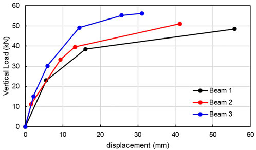
FIGURE 3. Vertical load vs. displacement (at LVDT3) curves for the laboratory PTC beams.
Regarding dynamic tests (NDT1), fundamental frequencies were calculated from the recorded signals. Then, modal shapes of the tested beams were also evaluated, particularly analyzing the first two vertical and two transverse modes, with the hypothesis of adopting two perfect hinges at the supports.
The first result is that the first fundamental frequency is affected by the flexural damage, as already well known from the literature (Casas and Aparicio, 1994; Gentile and Saisi, 2007; Venanzi et al., 2020; Pisani et al., 2021). Even if the fundamental frequency is not always highly sensible to damage occurrence, here, Figure 4 shows clearly the variation of this parameter (in the y-axis) with the applied flexural load (in the x-axis), at varying prestress force values. The reported results in terms of frequencies are the average from multiple readings; the coefficient of variation is very low in all the cases, about 1%. The lightest-colored lines identify the behavior of the beams with full prestress: from their curves, a decreasing trend of the fundamental frequency with the increase of the applied flexural load is visible. The maximum reduction ranges from 12 to 30% when the beams are fully damaged, depending on the strand disposition in the section. In the same figure, the darker-colored lines indicate the behavior of the beams with reducing prestress force while the fundamental frequency value is almost the same in the undamaged condition regardless of the prestress force, there is a non-negligible effect after the cracking condition. The reduction in the fundamental frequency occurs as a consequence of crack formation when the vertical load increases: the contribution of increasing the prestress force is to restrain the cracks opening, thus limiting the reduction of this parameter. Such results underline how a single dynamic test cannot give additional knowledge about the circumstance of a prestress loss, if the PTC member has no relevant cracks, i.e., detectable with a visual survey of the element surfaces. On the other side, if relevant cracks can be visually detectable, it may be not necessary to perform a dynamic test to conclude that a prestress loss occurred, thus concluding how a single dynamic test, without any other additional tests or information, cannot help to understand the condition state of PTC members in ordinary conditions (when they are in operation and do not show relevant crack patterns).
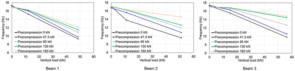
FIGURE 4. Average fundamental frequency as a function of the applied flexural load and prestressing force.
Modal shape changes were quantified by the Modal Assurance Criterion (MAC), which provides a measure of the correlation between two sets of modal shapes, evaluating their least square deviation (Ewins, 2009). A MAC value close to 1 means that modes differ little, while a value close to 0 means that the modes are totally different. Figure 5 shows MAC value variation for the first vertical mode for each of the analyzed PTC beams, resulting in a similar trend to those already observed for natural frequencies, even if characterized by less sensitivity to damage presence. The maximum reduction ranges from 3 to4% in the presence of a full damage imposed by the external flexural load; the influence of the prestress force is almost negligible. Such result seems to underline how in the case of PTC members continuously monitored with a SHM system, such performance indicator may not be the best choice to highlight the occurrence of non-negligible crack patterns.
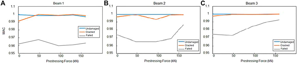
FIGURE 5. MAC index as a function of the applied flexural load (undamaged - cracked - failed) and prestressing force for the first vertical modal shape.
Regarding the ultrasonic tests (NDT2), first maps of the velocity were drawn from the interpolation of the collected values by developing an algorithm in the Matlab® environment (for more details see Frizzarin 2019). The results obtained from this technique were not encouraging: even if it was possible to identify a general decreasing trend of the UPV with the increase of damage (see Figure 6 for Beam 1, as an example, together with its cracking pattern at failure), for the highest levels of flexural applied load, the ultrasonic signal suffers for a great signal disturbance. Accordingly, it was not possible to calculate the signal velocity at each location of the beam, revealing a limitation of this method. Hence, similar conclusions can be drawn to those discussed for the few utility of dynamic tests for the quantification of potential prestress losses.
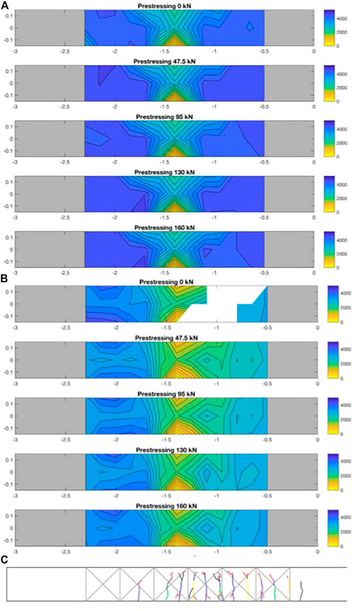
FIGURE 6. UPV tomography (m/s) in the vertical direction (PTC cross-section height = 0.3 m) of Beam 1 in (A) undamaged condition, (B) after complete damage, and (C) cracking pattern at failure.
Then, the attenuation of the ultrasonic signal was also evaluated through the computation of the area underlying the power spectral density (PSD) of the ultrasonic signal, measured in time. This calculation ensures to find a result for those signals that also suffer from disturb , where the time of flight of the signal (and therefore velocity) are difficult to be assessed clearly. Results of such analysis are presented in Figure 7 in the shape of tomographic contour plot. There, attenuation plots are presented for the case of Beam 1 in the undamaged condition (a) and after complete damage (b), using the data from the y-direction. This means that Figure 7 shows the attenuation across the beam height (0.3 m), over about 1.5 m length of the element. The main result is that moving from the null to full prestress acting in the element, the attenuation decreases, even if results are not always clear in average. The role of prestressing in the closure of cracks is to reduce the signal attenuation. Results show some correlation with flexural damage too, comparing the maps of Beam 1 when subject to complete damage to the undamaged condition, the UPV attenuation values are, in average, higher. Furthermore, these plots give a quite detailed view not only on the presence of the damage but also of the location of the cracks (see for comparison, Figure 6C).
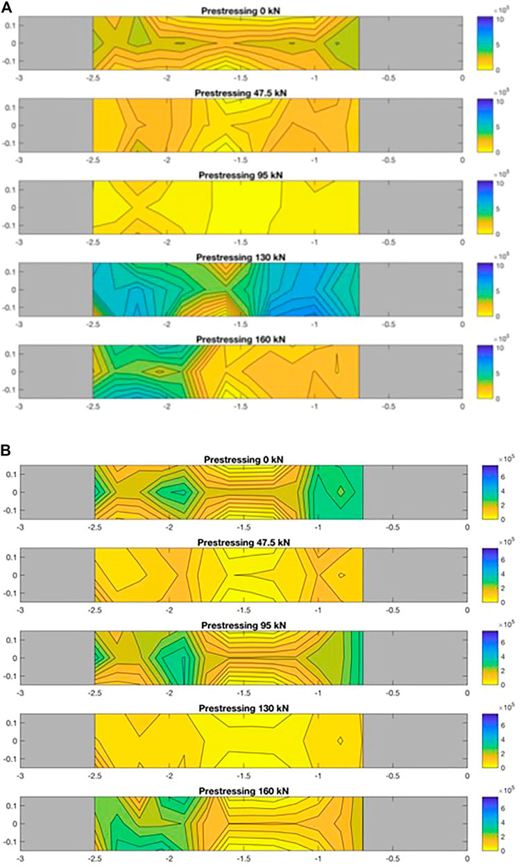
FIGURE 7. UPV attenuation (m/s) in the vertical direction (PTC cross-section height = 0.3 m) of Beam 1 in (A) undamaged condition and (B) after complete damage.
4 Tests on an in-service 50-year post-tensioned concrete bridge
In this section, the results of an experimental campaign on an in-service 50-year PTC bridge, built in 1968 in Padova district, Italy, are shown. The case study is a three-span bridge, with a single carriage and one vehicle and one pedestrian lane. The deck is made with four simply-supported double-T beams, with an average length of 32.10 m and height of 1.60 m (Figure 8). The distance between each web is 2.50 m, whereas the collaborating slab has 0.2 m width. Overall, the deck width is 10 m; the beams are transversally connected through intermediate elements, each placed at 8 m from the other. Concerning the prestressing steel, from the original design, it was possible to know that eight prestressing tendons are present in each beam, realized with a different number of single wires (with diameter ϕ = 7 mm), depending on their position. Furthermore, their tensile strength was fptk = 1650 MPa and their stress during exercise condition (after losses) was design to be about fpe = 889 MPa. The state of condition of the PTC beams is the objective of this study: particularly, here, different NDTs (endoscopies, stress-release methods, and XRD) were applied to investigate the residual prestress force acting on the grouted tendons. Preliminary, visual inspections, the assessment of material properties and the current tendons layout along the elements have been evaluated.
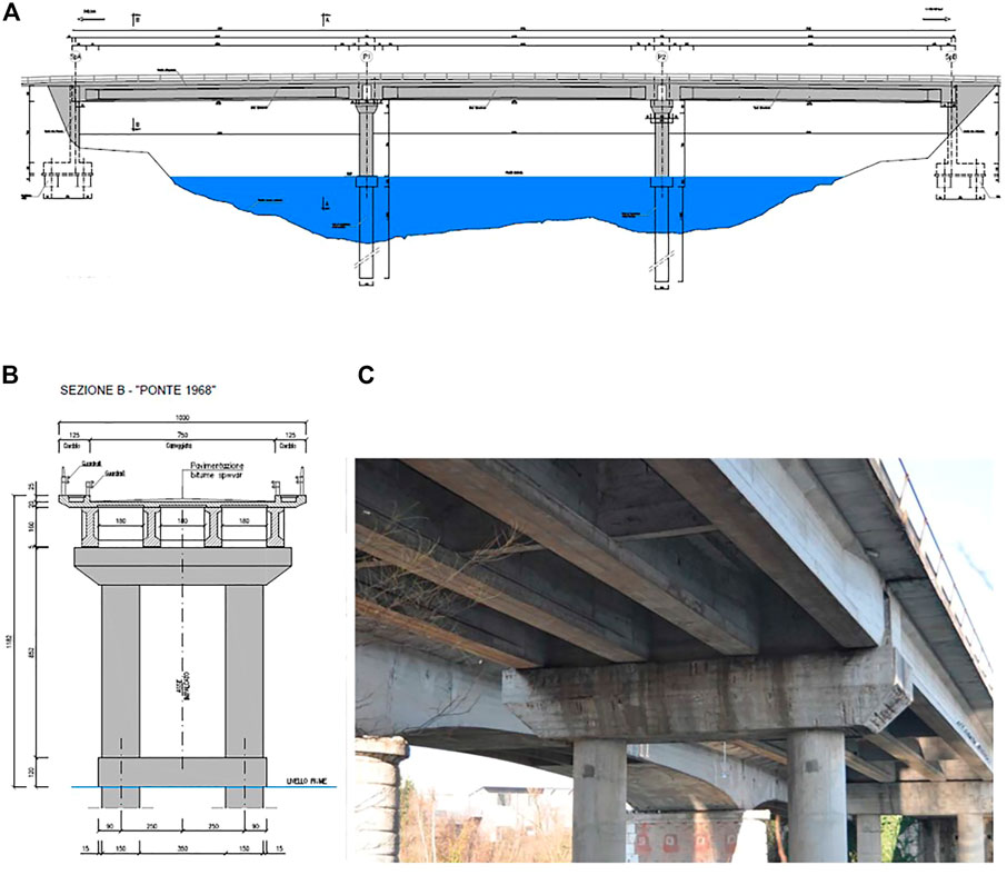
FIGURE 8. Case study: four PTC beams of a 50-year bridge with post-tensioned tendons and grouted ducts: (A) longitudinal view, (B) transversal cross-section, and (C) detail of the current condition state.
4.1 Preliminary tests: Visual inspection, material properties, and tendon disposition
A preliminary visual inspection was carried out to evaluate the main deterioration phenomena active on the structural elements. The state of conservation of the deck was found to be generally good with regard to the main prestressed beams, with no visible damage, the same applies for the slab intrados. This result was explained by the high quality of the concrete, the absence of obvious defects in drainage system, and almost ordinary environmental conditions (limited freezing/thawing cycles, no relevant sources for chlorides, limited air pollution), which are all factors that contributed to maintain sufficiently well the material properties. Instead, the piers cap and edge elements display some diffused deterioration, with concrete cover expulsion, steel bars oxidation, and some corrosion phenomena.
The results of two successive experimental campaigns performed in 2019 and 2021 were collected together, aiming at improving the knowledge on material properties. The main results deal with concrete cores and steel bars extraction and testing, other than some NDTs such as in situ SONREB tests (coupling ultrasonic and rebound tests with Schmidt hammer) on concrete and Brinell hardness tests on steel bars. The tests were carried out on the double-T beams, transverse beams, slab, pile caps, piles, and abutments. Specifically, for the double-T beams, the average in situ concrete compressive strength fc = 43.8 MPa, whereas the ordinary steel is characterized by yielding strength fy = 531 MPa. Concerning the slab, instead, material properties were characterized by fc = 57.0 MPa and fy = 459 MPa, for concrete and steel, respectively.
The cross-section, ordinary steel and prestressing tendon disposition in the PTC elements were investigated by means of visual inspection and electromagnetic method (i.e., using a covermeter for some details and GPR for both ordinary rebars, steel ducts localization, and prestressing tendons identification, adopting different acquisition setups depending on the type of reinforcement analyzed). According to the GPR results, it was possible to confirm the information available from the design of the bridge and to reconstruct the tendons layout. Specifically, Figure 9A shows the longitudinal profile of the tendons along the beams’ length, and three relevant sections of the beams with the details about the number of prestressing wires on each tendon. Note that from this technique no information about the possible presence if voids inside the tendons can be obtained. Indeed, the steel ducts reflect the waves and do not allow any penetration inside.
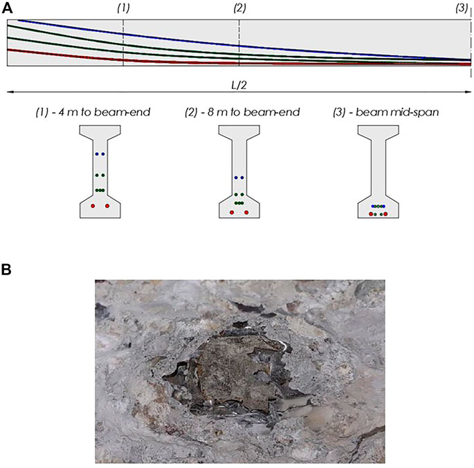
FIGURE 9. (A) Longitudinal profile of prestressing tendons along the beam length (half-span) and cross-section geometry of the double-T beams in three relevant sections and (B) condition state of the metallic duct and internal grout.
4.2 Non-destructive tests for prestress loss assessment
The following NDTs were carried out to obtain useful information about the current stress state of the prestressing steel:
• Micro-coring and endoscopies on two positions for each beam in two over three spans of the bridge (i.e., 16 point of measures)
• Tests based on stress release on both concrete and directly on the prestressing steel (one position for each beam)
• XRD tests (in the same position of stress release tests)
Particularly, the micro-cores were carried out to evaluate if there are voids or signs of corrosion in relevant positions that are the intrados of the PTC beams at the mid-span. In fact, in the absence of visible defects on, e.g., drainage system, which may be responsible for inducing damage in one specific section, the most vulnerable section is considered the mid-span. There, given the parabolic profiles of the prestressing tendons, they have the minimum concrete cover. Furthermore, due to their longitudinal profiles, if there were any segregation or bleeding phenomena in the grouted ducts during their realization, water would migrate to this position. It should also be recalled that, in the practice, the mid-span section is also the easiest to be accessed by the operators. However, it should be mentioned that this choice does not mean that any damage can be present in other positions.
In those positions, the cores were drilled until reaching the metallic ducts. At this stage, the cover was reported, and in one single case external corrosion of the duct was observed. In one case, indeed, the concrete cover was almost absent and signs of poor compaction were identified (honeycombs). Then, the ducts were cut and the grout was inspected to find any void, signs of poor compaction, bubbles, or presence of free water. None of these phenomena were observed and all wires seemed immersed in a good quality grout. Figure 9B shows an example of one analyzed duct.
Regarding the stress release methods, used also in this work, these techniques are generally based on the principle of estimating the current prestress force based on the stress released in a concrete member, measuring a strain value, as recently reviewed by (Kraľovanec et al., 2021a; Kraľovanec and Prokop, 2021b). These methods can be considered partially non-destructive, that is, they typically induce a local damage on the structure, which can however be promptly repaired with no long-term effects (neither for the statics nor for the durability) on the overall structure. Among them, the saw-cut method, stress-release coring (or drilling method), strand-cutting method (or wire-cutting), and exposed strand methods are worth to be cited (Kraľovanec et al., 2021c). A summarizing view of these methods is shown in Figure 10.

FIGURE 10. Indirect methods for prestress loss evaluation.
Here, the saw-cut method is applied, which is very similar to the drilling method: the technique is based on observing the changes in strain and stress in the area adjacent to the hole (or saw-cut isolated concrete block, in the companion method). The concrete block can be considered to be fully isolated when, increasing the cut depth, no further changes of the measured strain are read. Practically, the following procedure was followed: first, concrete surface was cleaned to guarantee a good adhesion of the electrical strain gages to the support (for their location, refer to Figure 11A); strain gages application and start of signal recording; cuts execution on the concrete surface with pyramid trunk shape in this case (see Figure 11B); final records after concrete de-heating. The concrete section was immediately repaired with a tyxotropic mortar.
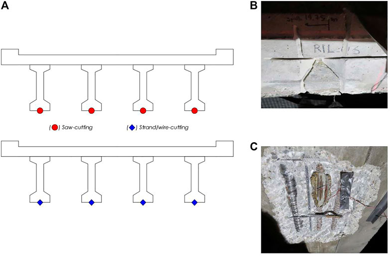
FIGURE 11. Stress-release method with saw-cut and wire-cut: location of test points (A), saw-cuts (B), and wire-cuts (C).
The results in terms of concrete stress obtained from this test can be, thus used to quantify the residual prestress force acting in the tendons, using, for example, finite element (FE) numerical models, or more simply, Navier’s formulation. In this last case, all the factors contributing to the strains at the monitoring point should be considered, that is, the prestress force in the member, including the influence of eccentricity in prestressing element positions; the restraint forces due, for instance, to eccentricity in the prestressing element positions in members that are not free to deform; the dead load of the member and the external applied load (Bagge et al., 2017). The results obtained here were reliable only for two points of measures over four: in half the cases, in fact, results could not be used due to a poor quality of the electrical signals and also because of the complexity of the methods. These tests have been rarely applied to real case structures with confirmed results but they found their main applications to relatively simple members (in terms of support conditions, member geometry, and prestressing reinforcement) in controlled environments. The thermal strains due to the cutting operations may be difficult to be quantified and subtracted from the overall reading. Overall, however, it was possible to obtain an average σc = 2.55 MPa at the beam intrados, which corresponds to about fse = 810 MPa, under current service loads.
The second stress release method is the wire-cutting: one of the wires belonging to a tendon is exposed for a minimum length of 15 cm in the present case, then a strain gauge is installed and used to measure the strains that develop when it is cut. Then, corresponding prestress force in the wire can be determined easily. Also in this case, the section was then immediately restored using a tyxotropic mortar. Compared to other test methods, this approach is slightly destructive because one single wire is cut; however, the stresses can be re-distributed in other wires of the tendons if the grout has sufficiently good quality. Figure 11A shows the location of the tests, whereas Figure 11C provides a detail of the application of the strain gage on one wire.
The results of this last test method were quite non-conclusive: the high variability of the readings made the results non-reliable. In three cases over four, the prestress loss obtained was sensibly high, indicating almost a complete loss of the prestress force acting in the tendon. In another case, no variation of the prestress force was recorded. Such results are in line with the observations made by Halsey and Miller (1996), who tested two 40-year-old PTC beams extracted from a bridge, applied the wire-cutting method, and compared to other destructive and non-destructive testing. They obtained that the wire-cutting method was responsible for the highest prestress loss results, and they indicated, as possible reasons, the following: the removal of surrounding concrete reduces the local confinement, and thus a higher prestress loss; the instantaneous cut of the wire releases high-energy, which may affect the electric signal of the strain gage; lastly, the reading from a single wire may be not accurate to describe the behavior of a whole tendon. The authors would also add another possible reason related to the thermal strains induced by the cutting operation that may affect the reading: in this case, they are even higher than in the saw-cut method due to the higher coefficient of thermal expansion of high-alloy alloy (up to 1.7·10−5 (°C−1)) steel than concrete (1.2 · 10−5 (°C−1)).
The last test method is the XRD, which has been briefly discussed in Section 2. The test was carried out on the same positions for the wire-cut but on more wires. Specifically, two-three wires were investigated for each measure point, in most cases repeating the reading to validate the result obtained. In detail, here the XRD-sin2(ψ) technique was adopted (Prevey, 1986), originally developed from the theories of crystallography and solid mechanics and applied for the surface residual stress evaluation mainly on thin films, coatings, and metals (Matejicek et al., 1998; Ma et al., 2002; Yazdanpanah et al., 2021a; Yazdanpanah et al., 2021b). In fact, since X-rays have a limited penetration in solid surfaces, the method allows measuring the stresses in a depth of a few micrometers as maximum.
The main assumption at the base of the method is that a plane stress-state applies, see Figure 12, which shows the in-plane stress σϕ with respect to the two principal stress components σ1 and σ2. When a X-ray beam hits the surface of the test sample at an incident angle Ω, the (hkl) lattice planes meeting the Bragg diffraction condition and having an off-axis angle ψ with respect to the sample surface normal, emit a diffraction X-ray beam at a diffraction angle 2θ (Luo and Jones, 2010). Accordingly, the spacing dϕψ of the (hkl) lattice plane is measured. Knowing the elastic properties of the materials (E and υ) in the normal direction to the (hkl) orientation of the material and the initial lattice spacing in the unloaded (null stress) condition d0, the following equation can be used:
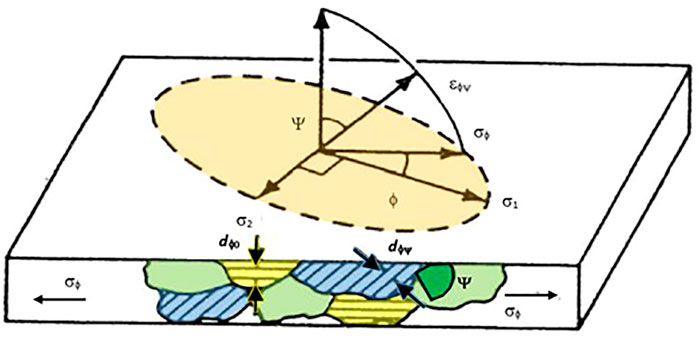
FIGURE 12. Plane-stress elastic model (adapted from Prevéy, 1986).
Thanks to the almost complete knowledge of the steel alloys used to realize construction materials, and particularly both ordinary and prestressing reinforcement, material properties and d0 can be easily known. From Eq. (2), it is possible to obtain, under certain assumption, the surface stress acting on the material, according to the following equation:
For a complete review of this technique, the work by Prevey (1986) is referred. Note that in the practice, the methods require that for a single determination of a
The portable XRD was mounted on a support to anchor the instrumentation at the deck intrados, allowing a minimum distance of the emitters/detectors to the whole length (about 50 cm) of the wires analyzed. Figure 13 shows an example of the tests carried out. Preliminary to carry out the readings, the wires were prepared: particularly, their surface was manually cleaned and then a chemical pickling was made, adopting a solution with sulfuric and hydrochloric acid, and demineralized water. Overall, for each measure point, 15 min are necessary to obtain one stress value. Furthermore, surface preparation time should be considered.
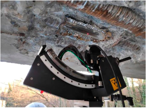
FIGURE 13. XRD tests execution on the bridge PTC beams.
The results found through this method have a good repeatability and show consistency among themselves: for instance, repeating the reading two times on the same wire, results differ by 50–60 MPa. In fact, for Beam 1 and Beam 2, respectively, the results of successive readings on single wires were: 666 ± 20 MPa and 657 ± 21 MPa; 778 ± 63 MPa and 713 ± 44 MPa. The variability among the results is considered sufficiently limited, overall. Furthermore, the values obtained from this test are associated to higher prestress loss than those obtained from the saw-cut method, this probably being due to the direct exposition of the wires and the reduction of local confinement.
5 Conclusion
This work discussed pros and cons of different test methods to evaluate the actual prestress state in the prestressing steel reinforcement of post-tensioned concrete members. The failure of some PTC structures has raised the attention on this peculiar structural type, particularly for those elements having grouted ducts with non-accessible tendons. The assessment of current prestress in these members still represents a challenging objective because direct methods cannot be applied, unless tendons were instrumented at the time of realization, or they provide non-reliable results. An in-depth review of the current methods proposed in the literature and in practical applications was first performed. Then, recent authors experience both in laboratory tests and in situ applications were illustrated in detail with the aim to provide an additional contribution to the state-of-the-art of the scientific literature devoted to identify the most proper investigation techniques to be implemented for the quantification of prestress losses in PRC elements.
In detail, through two experimental campaigns, carried out both at the laboratory scale and in-field on an existing in-service PTC bridge, we have shown which results can be obtained with different techniques. Based on the authors’ experience, vibration-based methods can be applied satisfactorily to identify existing damage; however, when the beams are still not cracked, the variation of the main dynamic parameters is too small to identify any significant prestress variation. In addition, the mutual connection of beams with other deck elements like slab, pavements, and bearings can significantly impact on the dynamic properties of the simply-supported beams individually considered. This issue implies additional efforts to carefully quantify the contribution of each component to the overall stiffness of a bridge deck that can rarely lead to a clear interpretation of the condition state of the prestressed beams. On the other hand, a promising technique is the evaluation of the UPV attenuation signal: when the test is carried out in the tomography configuration and the whole signal is recorded and analyzed, attenuation maps can be developed, showing a correlation with damage patterns. However, some criticalities have been observed for higher damage levels, where the ultrasonic signal suffers for a great signal disturbance.
Concerning indirect methods, according to the authors’ opinion, an integrated approach should be preferred coupling different test methods, starting from visual inspections, endoscopies, and lastly, point measure such as saw-cut tests and XRD ones. In this regard we presented the results on a real-scale bridge, where some of these methods were applied, combining the use of the aforementioned different NDTs and comparing their results. In summary, based on such experience, the XRD method, even very recent in the field of bridge engineering, has shown very promising results, as also recently suggested by Morelli et al. (2021).
Lastly, as final remark, authors want to underline how a direct comparison between experimental results coming from laboratory tests and in situ measurements can be strongly flawed for the two following aspects that characterize the existing bridge decks as compared to the experimental layouts: 1) deterioration phenomena that can affect with unknown patterns the capacity of the beams and 2) the internal redundancy of real bridge decks—even if statically determined if considered as a whole—that can in turn give place to a beneficial redistribution of internal actions in case of prestress losses.
Data availability statement
The original contributions presented in the study are included in the article/supplementary material; further inquiries can be directed to the corresponding author.
Author contributions
MZ, FF, and CP contributed to the conception and design of the study and performed the analysis of the results. FF wrote the first draft of the manuscript. MZ and CP wrote sections of the manuscript. MZ, FF, and CP reviewed the final version of the manuscript. All authors contributed to manuscript revision and read and approved the submitted version.
Acknowledgments
The authors would like to acknowledge all the colleagues that contributed to this work: Manuele Dabalà, Claudio Gennari, and Luca Pezzato from the University of Padova for their expertise on the XRD residual stress technique; Michele Frizzarin, Paolo Franchetti (from the Franchetti SpA), and Eng. Filippo Andreose (from the University of Padova) for their work on the PTC laboratory beams and the elaboration of data (fully published in Frizzarin PhD thesis); and Eng. Silvano Vernizzi and Eng. Alessandro Zago (from Veneto Strade SpA) for the availability in carrying out the tests on the case study. Veneto Strade SpA is particularly thanked for the financial support and for giving the possibility to carry out and use the test results on the existing bridge. All the private partners (laboratories and engineers) who participated in the experimental tests of the case study are gratefully acknowledged. Finally, this work was developed within the Italy–Croatia INTERREG Project FIRESPILL—Fostering Improved Reaction of crossborder Emergency Services and Prevention Increasing safety LeveL.
Conflict of interest
The authors declare that the research was conducted in the absence of any commercial or financial relationships that could be construed as a potential conflict of interest.
Publisher’s note
All claims expressed in this article are solely those of the authors and do not necessarily represent those of their affiliated organizations, or those of the publisher, the editors, and the reviewers. Any product that may be evaluated in this article, or claim that may be made by its manufacturer, is not guaranteed or endorsed by the publisher.
References
Aliofkhazraei, M., Dukeman, D., and Alexander, C. L. (2021). “The susceptibility of prestressing strands within grouted post-tensioned tendons to hydrogen embrittlement: A review,” in Corrosion 2021 (NACE) (Houston, TX: Four Point Publishing LCC).
Anania, L., Badalà, A., and D’Agata, G. (2018). Damage and collapse mode of existing post tensioned precast concrete bridge: The case of Petrulla viaduct. Eng. Struct. 162, 226–244.
Angst, U., Moro, F., Geiker, M., Kessler, S., Beushausen, H., Andrade, C., et al. (2020). Corrosion of steel in carbonated concrete: Mechanisms, practical experience, and research priorities–a critical review by RILEM TC 281-CCC. RILEM Tech. Lett. 5, 85–100. doi:10.21809/rilemtechlett.2020.127
Azizinamini, A., Keeler, B., Rohde, J., and Mehrabi, A. B. (1996). Application of a new nondestructive evaluation technique to a 25-year-old prestressed concrete girder. pcij. 41, 82–95. doi:10.15554/pcij.05011996.82.95
Badalassi, M., Braconi, A., Cajot, L. G., Caprili, S., Degee, H., Gündel, M., et al. (2017). Influence of variability of material mechanical properties on seismic performance of steel and steel–concrete composite structures. Bull. Earthq. Eng. 15 (4), 1559–1607. doi:10.1007/s10518-016-0033-2
Bagge, N., Nilimaa, J., and Elfgren, L. (2017). In-situ methods to determine residual prestress forces in concrete bridges. Eng. Struct. 135, 41–52. doi:10.1016/j.engstruct.2016.12.059
Berto, L., Caprili, S., Saetta, A., Salvatore, W., and Talledo, D. (2020). Corrosion effects on the seismic response of existing rc frames designed according to different building codes. Eng. Struct. 216, 110397. doi:10.1016/j.engstruct.2020.110397
Calabrese, L., and Proverbio, E. (2020). A review on the applications of acoustic emission technique in the study of stress corrosion cracking. Corros. Mater. Degrad. 2 (1), 1–33. doi:10.3390/cmd2010001
Calvi, G. M., Moratti, M., O'Reilly, G. J., Scattarreggia, N., Monteiro, R., Malomo, D., et al. (2019). Once upon a time in Italy: The tale of the morandi bridge. Struct. Eng. Int. 29 (2), 198–217. doi:10.1080/10168664.2018.1558033
Casas, J. R., and Aparicio, A. C. (1994). Structural damage identification from dynamic-test data. J. Struct. Eng. (N. Y. N. Y). 120 (8), 2437–2450. doi:10.1061/(asce)0733-9445(1994)120:8(2437)
COST TU1406 (2014). Quality specifications for roadway bridges, standardization at a European level (Bridgespec). Brussels: European Cooperation in the field of Scientific and Technical Research.
COST345 (2004). “Procedures required for the assessment of highway infrastructures,” in European research project under the framework of European cooperation in the field of scientific and technical research (Brussels: EU Commission-Directorate General Transport and Energy).
Crespo-Minguillon, C., and Casas, J. R. (1997). A comprehensive traffic load model for bridge safety checking. Struct. Saf. 19 (4), 339–359. doi:10.1016/s0167-4730(97)00016-7
Faleschini, F., Zanini, M. A., and Pellegrino, C. (2018). “Quality control, infrastructure management systems and their implementation in medium-size highway networks,” in Proc eBook for the 8th Workshop meeting Barcelona EUROSTRUCT (Guimaraes, Portugal: EUROSTRUCT Association).
Frizzarin, M. (2019). An experimental study on the correlation between residual prestress force in pre-tensioned and post-tensioned concrete beams and nondestructive tests. Ph.D. Thesis. Padova (Italy): University of Padova. Available At: https://www.research.unipd.it/handle/11577/3423298.
Garber, D. B., Gallardo, J. M., Deschenes, D. J., and Bayrak, O. (2015). Experimental investigation of prestress losses in full-scale bridge girders. ACI Struct. J. 112 (5), 7909. doi:10.14359/51687909
Gentile, C., and Saisi, A. (2007). Ambient vibration testing of historic masonry towers for structural identification and damage assessment. Constr. Build. Mater. 21 (6), 1311–1321. doi:10.1016/j.conbuildmat.2006.01.007
Halsey, J. T., and Miller, R. (1996). Destructive testing of two forty-year-old prestressed concrete bridge beams. pcij. 41 (5), 84–93. doi:10.15554/pcij.09011996.84.93
Kraľovanec, J., Bahleda, F., Prokop, J., Moravčík, M., and Neslušan, M. (2021a). Verification of actual prestressing in existing pre-tensioned members. Appl. Sci. 11 (13), 5971. doi:10.3390/app11135971
Kraľovanec, J., Moravčík, M., Bujňáková, P., and Jošt, J. (2021c). Indirect determination of residual prestressing force in post-tensioned concrete beam. Materials 14 (6), 1338. doi:10.3390/ma14061338
Kraľovanec, J., and Prokop, J. (2021b). Indirect methods for determining the state of prestressing. Transp. Res. Procedia 55, 1236–1243. doi:10.1016/j.trpro.2021.07.105
Luo, Q., and Jones, A. H. (2010). High-precision determination of residual stress of polycrystalline coatings using optimised XRD-sin2ψ technique. Surf. Coatings Technol. 205 (5), 1403–1408. doi:10.1016/j.surfcoat.2010.07.108
Ma, C. H., Huang, J. H., and Chen, H. (2002). Residual stress measurement in textured thin film by grazing-incidence X-ray diffraction. Thin solid films 418 (2), 73–78. doi:10.1016/s0040-6090(02)00680-6
Martin, J., Broughton, K. J., Giannopolous, A., Hardy, M. S. A., and Forde, M. C. (2001). Ultrasonic tomography of grouted duct post-tensioned reinforced concrete bridge beams. Ndt E Int. 34 (2), 107–113. doi:10.1016/s0963-8695(00)00035-9
Matejicek, J., Sampath, S., and Dubsky, J. (1998). X-ray residual stress measurement in metallic and ceramic plasma sprayed coatings. J. Therm. spray Technol. 7 (4), 489–496. doi:10.1361/105996398770350701
Ministry of Italian Infrastructure (2020). Guidelines on Risk classification and management, safety assessment and monitoring of existing bridges. Rome, Italy: Consiglio Superiore dei Lavori Pubblici.
Moravčík, M., and Bujňáková, P. (2017). Analysis of brittle failure of prestressed bridge in the north of Slovakia. Rocz. Inżynierii Bud., 27–34.
Morelli, F., Panzera, I., Piscini, A., Salvatore, W., Chichi, F., Marconi, G., et al. (2021). X-ray measure of tensile force in post-tensioned steel cables. Constr. Build. Mater. 305, 124743. doi:10.1016/j.conbuildmat.2021.124743
Oh, B. H., and Yang, I. H. (2000). Sensitivity analysis of time-dependent behavior in PSC box girder bridges. J. Struct. Eng. (N. Y. N. Y). 126 (2), 171–179. doi:10.1061/(asce)0733-9445(2000)126:2(171)
Osborn, G. P., Barr, P. J., Petty, D. A., Halling, M. W., and Brackus, T. R. (2012). Residual prestress forces and shear capacity of salvaged prestressed concrete bridge girders. J. Bridge Eng. 17 (2), 302–309. doi:10.1061/(asce)be.1943-5592.0000212
Pisani, M. A., Limongelli, M. P., Giordano, P. F., and Palermo, M. (2021). On the effectiveness of vibration-based monitoring for integrity management of prestressed structures. Infrastructures 6 (12), 171. doi:10.3390/infrastructures6120171
Prevéy, P. S. (1996). Current applications of X-ray diffraction residual stress measurement. Dev. Mater. Charact. Technol. 103.
Prevey, P. S. (1986). X-ray diffraction residual stress techniques. ASM Int. ASM Handb. 10, 380–392.
Quirk, L., Matos, J., Murphy, J., and Pakrashi, V. (2018). Visual inspection and bridge management. Struct. Infrastructure Eng. 14 (3), 320–332. doi:10.1080/15732479.2017.1352000
Saiidi, M., Douglas, B., and Feng, S. (1994). Prestress force effect on vibration frequency of concrete bridges. J. Struct. Eng. (N. Y. N. Y). 120 (7), 2233–2241. doi:10.1061/(asce)0733-9445(1994)120:7(2233)
SAMARIS (2005). “Sustainable and advanced materials for road infrastructure,” in VI framework programme (Brussels: SAMARIS Consortium).
Tu, B., Dong, Y., and Fang, Z. (2019). Time-dependent reliability and redundancy of corroded prestressed concrete bridges at material, component, and system levels. J. Bridge Eng. 24 (9), 04019085. doi:10.1061/(asce)be.1943-5592.0001461
Venanzi, I., Kita, A., Cavalagli, N., Ierimonti, L., and Ubertini, F. (2020). Earthquake-induced damage localization in an historic masonry tower through long-term dynamic monitoring and FE model calibration. Bull. Earthq. Eng. 18 (5), 2247–2274. doi:10.1007/s10518-019-00780-4
Yazdanpanah, A., Biglari, F. R., Fallahi Arezoodar, A., and Dabalà, M. (2021a). Role of grinding induced surface residual stress on probability of stress corrosion cracks initiation in 316L austenitic stainless steel in 3.5% sodium chloride aqueous solution. Corros. Eng. Sci. Technol. 56 (1), 81–92. doi:10.1080/1478422x.2020.1812818
Yazdanpanah, A., Franceschi, M., Bergamo, G., Bonesso, M., and Dabalà, M. (2022). On the exceptional stress corrosion cracking susceptibility of selective laser melted 316L stainless steel under the individual effect of surface residual stresses. Eng. Fail. Anal. 136, 106192. doi:10.1016/j.engfailanal.2022.106192
Yazdanpanah, A., Lago, M., Gennari, C., and Dabalà, M. (2021b). Stress corrosion cracking probability of selective laser melted 316l austenitic stainless steel under the effect of grinding induced residual stresses. Metals 11 (2), 327. doi:10.3390/met11020327
Zanini, M. A., Faleschini, F., and Pellegrino, C. (2017a). Bridge residual service-life prediction through Bayesian visual inspection and data updating. Struct. Infrastructure Eng. 13 (7), 906–917. doi:10.1080/15732479.2016.1225311
Keywords: dynamic identification, non-destructive tests, post-tensioned concrete, prestress loss, structural assessment, x-ray diffraction, bridges
Citation: Zanini MA, Faleschini F and Pellegrino C (2022) New trends in assessing the prestress loss in post-tensioned concrete bridges. Front. Built Environ. 8:956066. doi: 10.3389/fbuil.2022.956066
Received: 29 May 2022; Accepted: 20 October 2022;
Published: 08 November 2022.
Edited by:
Joan Ramon Casas, Universitat Politecnica de Catalunya, SpainReviewed by:
Michele Fabio Granata, University of Palermo, ItalyYuguang Yang, Delft University of Technology, Netherlands
Copyright © 2022 Zanini, Faleschini and Pellegrino. This is an open-access article distributed under the terms of the Creative Commons Attribution License (CC BY). The use, distribution or reproduction in other forums is permitted, provided the original author(s) and the copyright owner(s) are credited and that the original publication in this journal is cited, in accordance with accepted academic practice. No use, distribution or reproduction is permitted which does not comply with these terms.
*Correspondence: Mariano Angelo Zanini, bWFyaWFub2FuZ2Vsby56YW5pbmlAdW5pcGQuaXQ=