 Axel Trautwein
 Tamara Prokosch
 Gennaro Senatore
 Lucio Blandini
 Manfred Bischoff
- 1Institute for Structural Mechanics, University of Stuttgart, Stuttgart, Germany
- 2Institute for Lightweight Structures and Conceptual Design (ILEK), University of Stuttgart, Stuttgart, Germany
This paper discusses the role that structural stiffness plays in the context of designing adaptive structures. The focus is on load-bearing structures with adaptive displacement control. A design methodology is implemented to minimize the control effort by making the structure as stiff as possible against external loads and as flexible as possible against the effect of actuation. This rationale is tested using simple analytical and numerical case studies.
1 Introduction
The integration of load-bearing structures with active elements can improve the performance of a certain amount of available material or, vice versa, reduce the material required to achieve a target performance. When strategic changes in the geometry and stiffness of parts of the structure are developed through actuation, it is possible to counteract the effect of external loads by reducing and optimizing stress, deformation, and vibration states. Early work in the design and application of adaptive structures was carried out by Zuk and Clark (1970) and Domke (1992), showing the potential for material savings compared to conventional passive structures. Early concepts of design and control methods for structures equipped with active components, primarily for vibration control, are given by Soong (1988), Wada (1990), Reinhorn et al. (1993), Utku (1998), and Adam and Smith (2008). A comprehensive state-of-the-art review up to 2011 is provided in Korkmaz (2011). Recent investigations are reviewed by Neuhäuser et al. (2013) and Schwegmann (2022).
For civil engineering applications, Sobek and Teuffel (2001), Senatore et al. (2011), Geiger et al. (2020a), Reksowardojo et al. (2022), and Blandini et al. (2022), among others, have shown that structural adaptation is particularly beneficial for stiffness-governed structures such as high-rise buildings and long-span roof structures. The first adaptive high-rise building, named D1244, is a 36.5-m tower equipped with 12 actuators that has been realized within the framework of the Collaborative Research Center SFB 1244 “Adaptive Skins and Structures for the Built Environment of Tomorrow” (Blandini et al., 2022). Investigation on adaptive bridge structures has also been carried out. A lightweight and flexible stress-ribbon footbridge equipped with pneumatic muscle actuators fitted in the handrail was implemented by Bleicher et al. (2011). Experimental testing was carried out on a small-scale model of a single-span beam bridge known as the Stuttgarter Träger (Teuffel, 2004). Displacements caused by a moving load were controlled through the action of a linear actuator that, by changing the orientation of the end support, caused a counteracting bending moment. Recent studies on active vibration control (Reksowardojo et al., 2022) have focused on retrofitting high-speed railway bridges with adaptive tensioning systems, showing that it is possible to reduce the acceleration peaks caused by train crossings to acceptable limits without incurring a weight penalty due to oversizing.
Generally, relying on stiffness generated through material resistance to satisfy serviceability requirements results in oversizing as most civil structures are subjected to strong but rarely occurring loading events. Instead, structural adaptation enables a significant reduction of material, carbon, and energy requirements because deflection limits can be satisfied through geometry and stiffness control when required, that is, upon the occurrence of a strong loading event. The design philosophy adopted in most studies on adaptive structures is to employ active control to satisfy serviceability limit states (SLS). However, active control is typically not required to satisfy ultimate limit states (ULS), thus avoiding the risk of loss of load-bearing capacity in the event of control system failure and concurrent occurrence of extreme loading events. A holistic design and optimization approach for adaptive structures was developed by Senatore et al. (2019). The structural elements are sized to take the ULS without requiring active control (i.e., passively) but ignoring geometric compatibility and displacement limits (SLS), typically producing very flexible and lightweight structures for stiffness-governed problems. Then, actuators are optimally placed, and control commands are obtained to satisfy SLS requirements using minimum actuation energy. This approach was further developed into an all-in-one (AIO) optimization formulation by mixed-integer programming whereby cross-section sizing, actuator placement, and control commands are obtained simultaneously (Wang and Senatore, 2020; Wang and Senatore, 2021). In these studies, adaptive structures are designed by simultaneously minimizing the energy embodied in the material (sizing optimization) and the energy required for adaptation during service (actuator placement and control commands).
The work presented in this paper offers an alternative strategy to design structures that use active displacement control to comply with serviceability requirements. Basic design principles are employed to minimize the actuation effort by strategically tailoring the structural stiffness. Serviceability requirements typically concern the deflection and acceleration limits of the structural response under loading. For passive structures, satisfying serviceability limits results in material strength and element capacity being inefficiently exploited because stiffness requirements lead to over-dimensioning the load-carrying capacity. Alongside the amount of required material mass, an important indicator of the efficiency of adaptive structures is the required actuation effort. Reduction of material mass and deflections are contrasting objectives because stiff structures that embody large material mass undergo small deformations under loading. However, flexible structures with smaller material embodiment typically require smaller actuation energy for displacement control. As discussed by Senatore et al. (2019) and Geiger et al. (2020b), the design of adaptive structures requires a paradigm shift that accounts for adaptation early in the design phase. The performance of passive structures that are optimal with respect to a certain objective—for example, limiting displacements by stiffness maximization—could be further improved through adaptation. However, the resulting adaptive structure would be suboptimal. For example, a structure having low performance in the passive state in terms of stiffness but purposefully designed to be adaptive could have significantly better performance if strategically integrated with active components. Generally, as shown by Senatore et al. (2019) and Geiger et al. (2020b), a holistic design of the adaptive system leads to higher quality solutions than those obtained by first designing an (optimal) passive structure and subsequently improving its performance through adaptation. This paper discusses basic principles for designing adaptive structures using simple problems that can be solved analytically. The main contribution of this work is to show how optimal solutions can be obtained to fulfill the conflicting objectives of a structure to be as stiff as possible against external loads and as flexible as possible to minimize actuation energy for displacement control. The working hypotheses derived from analytical studies are tested through numerical examples.While referring to typical structural configurations, such as beams, floor slabs, and trusses, the analytical and numerical studies formulated in this work are mainly intended to illustrate the advantages of active displacement control in different scenarios.
The paper is structured as follows: in Section 2, strategies for designing adaptive structures are discussed using simple configurations for which it is possible to obtain analytical solutions. Section 3 presents numerical studies in which the analytically derived solutions are verified through finite element analyses, including an adaptive ribbed slab configuration. Finally, the results are summarized and discussed in Section 4.
2 Analytical case studies
2.1 General concept
In the following subsections, conceptual case studies show the interaction between load, structural stiffness, and actuation effort for structures with active displacement control. The structural configurations under examination are designed so that response analysis and optimization of design parameters are obtained through exact analytical solutions. This allows for a rigorous assessment of the basic concepts proposed herein.
2.2 Tapered beam with single force actuation
2.2.1 Problem setup
An elastic beam of length 2l is pinned at both ends and subjected to a uniformly distributed load q. The cross section is symmetrically tapered along the beam’s length, defined by a constant width b, mean height (i.e., thickness) h0, and a tapering constant α, as indicated in Figure 1. A single vertical actuation force Fact is applied at the center of the beam. Fact could be applied by a hydraulic actuator (Kelleter et al., 2020), and it is assumed that it is slack in the passive state; that is, it does not contribute to the (passive) structural stiffness. Applying symmetry boundary conditions at mid-span, only the left half of the system is modeled. The cross-sectional height of the symmetric structure is defined by the function
For α = 0, the height is constant, h = h0, while for α = 1, it is zero at the supports and h = 2h0 at mid-span. Vice versa, for α = −1, the height is h(0) = 2h0 at the supports and h(l) = 0 at mid-span. In the following, α is restricted to
to exclude impractical small cross sections. An exemplary evaluation of h(x) for a few values of α is shown in Supplementary Material S1. The volume of the beam is
which is independent of α. The structure is modeled as a straight beam, neglecting the small inclination of its axis resulting from the tapering. Bernoulli beam theory is employed for a linear elastic analysis. One load case q is considered. The observed system response is the mid-span deflection wl, subject to the constraint
where
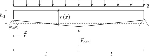
FIGURE 1. Tapered beam: problem setup and definition of geometry. Refer to Eq. 1 for the definition of h(x) as a function of the mean thickness h0 and parameter α.
2.2.2 Passive system
Consider the passive system (Fact = 0). Because the structure is statically determinate, the bending moment can be obtained directly from equilibrium and boundary conditions as
which is independent of the cross section. The bending stiffness is
Inserting the curvature equation
The deflection as a function of the position along the beam is given in Supplementary Material S2. The passive system is optimized through volume (mass) minimization, ensuring that the deflection limit is satisfied without actuation. The problem formulation is
As the objective function is linear, the constraint is active at the optimum,
The tapering coefficient α is identical for all solutions, ensuring maximum stiffness for a given volume determined by the average cross-section height h0.
When α is positive, more material is placed in the beam mid-span, increasing the stiffness in the region of significant bending moment. The average cross-section height h0 increases as
2.2.3 Adaptive system, design for minimum actuation effort
The adaptive system is equipped with a single actuator applying a vertical force Fact. Taking the values from Section 2.2.2 as a reference, the volume of the beam is restricted to V = 1.0 m3 (i.e., h0 = 0.2 m). Considering the benchmark solutions for the passive system, it is clear that this leads to a displacement
The average cross-section height h0 is fixed in this study; therefore, the tapering coefficient α is the only design variable. Different strategies are tested to minimize the actuation force.
Strategy n1 is to optimize the passive system for stiffness to minimize the difference displacement
that must be compensated by actuation. In Eq. 8, wpas is the displacement of the passive system (i.e., uncontrolled displacement). From previous results (Section 2.2.2), optimizing the passive stiffness yields a value of α = 0.5374. The corresponding non-controlled displacement (i.e., without actuation) is wpas = 0.0452 m. The actuation forces required to meet different deflection requirements and the mass reductions compared to the benchmark passive system are
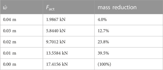
A mass reduction of 100% is theoretically possible because the passive system would need an infinite stiffness to satisfy a zero deflection limit. It has been pointed out by Geiger et al. (2020b) and proved numerically through the formulations given in Senatore et al. (2019) and Wang and Senatore (2020) that a holistic optimization of the adaptive system leads to better quality solutions than fitting actuation to an optimized (stiffness maximized) passive structure.
Following these approaches, strategy n2 and the corresponding optimization problem can be formalized as follows.
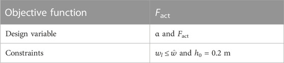
Analytic expressions of the problem solution are derived as mentioned previously. In particular, the objective function is given as
The formula of Fact is reported in Supplementary Material S3. Minimization for different deflection limits
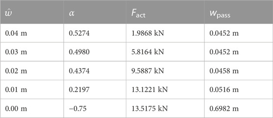
Mass reduction is the same as strategy n1 because the volume has been prescribed. Instead, the displacements wpass obtained for the passive case (Fact = 0 kN) are given. The actuation forces Fact are smaller than those required to control the mass-optimized structure in the passive state (i.e., strategy n1). That being said, the difference in the required actuation forces is marginal because, given a certain volume, the load-carrying behavior of this simple statically determinate system is only marginally affected by α. The differences are more pronounced for the underslung beam structure investigated in Section 2.3.
The reduction of the actuation force becomes more important as the deflection limit becomes tighter. The uncontrolled displacement of the optimal structure gradually increases as
Strategy n3 is derived from these observations. To minimize the displacement to be compensated, the difference
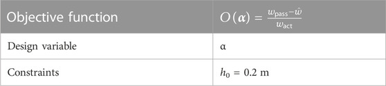
The analytical computation shows that the objective function is identical to the expression for Fact in Eq. (9) and that optimization strategy n3 gives the same solution as strategy n2, which minimizes the required actuation force. This observation can be explained by computing the actuation force from the displacement wact caused by a unit actuation and the required displacement compensation Δw,
In this case, the solutions are identical owing to the simple problem setup that considers a single displacement variable. However, a more general statement can be formulated:
“To minimize the actuation effort for displacement control, the structural design should maximize stiffness against the external loads and minimize stiffness against actuation.”
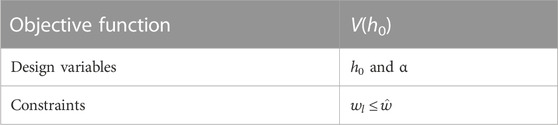
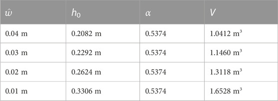
An overview of the results (for Δw = 0.01 m) of the different optimization strategies is shown in Table 1. Strategy n2 and strategy n3 produce identical solutions. Strategy n1 gives a different solution requiring a slightly higher actuation force.
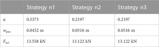
TABLE 1. Tapered beam, optimization results.
Generally, because the effect of external loads and actuation forces lead to different deformation modes, there is a certain potential to realize both apparently contrasting objectives. This is demonstrated in the following section by a simple example structure with two different load-carrying mechanisms.
2.3 Underslung beam
2.3.1 Problem setup
An underslung beam, shown in Figure 2 is subjected to a uniform load q0. In addition, the self-weight g of the beam is considered. The displacements wA and wB at locations A and B indicated in Figure 2 are observed. The stiffness of the structure comprises the bending stiffness of the beam, which depends on the cross-section height, h, and the stiffness of the underslung cable, which depends on the diameter, d. The geometry is chosen to balance the stiffness provided by the cable and the bending stiffness of the beam. As only linear analyses are performed in this study, the effects of prestress and geometric stiffness in the cable are neglected.
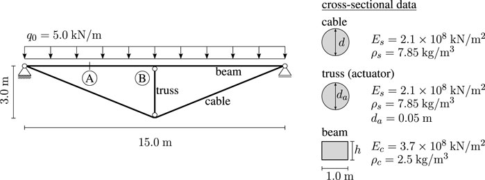
FIGURE 2. Underslung beam, system data.
The displacements are limited to wmax = 2 cm. In addition, the mid-span displacement wB should be as small as possible. For example, the vertical member is equipped with a linear actuator that can change its length as a hydraulic actuator. Thus, wB can be controlled to be exactly zero, and, as in the previous section, the actuation effort is minimized to achieve this objective. The objective to completely reduce the mid-span displacement is motivated by the aim to showcase the interplay between (passive) structural stiffness and the contribution of actuation, in this case, realizing an apparently infinite stiffness at the midpoint for the adaptive system. The total reduction of displacements through actuation has been experimentally verified in previous work (Senatore et al., 2017). In the following, N denotes the total normal force in the actuator. Nact is the actuation contribution to the total force. While the element force N is caused only by elastic deformation in the uncontrolled state, in the controlled state, the force is the sum of the elastic deformation of the element and the inelastic deformation caused by the actuator length change. The actuation contribution to the total force is denoted as Nact. Nact is used as a simple measure to quantify actuation effort. The passive case is considered first for the benchmark.
2.3.2 Passive system
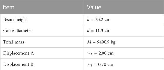
The minimum mass required to satisfy the displacement limit is obtained by solving the following optimization problem.
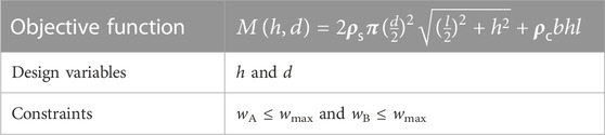
The problem can be solved analytically, and the following values are obtained.
The normal force in the (passive) vertical member is N = −330.84 kN.
2.3.3 Adaptive system
The vertical actuator can reduce the mid-span displacement wB to zero. Using the passive configuration obtained in the previous section, an elongation Δl = 0.71 cm is required. The value is marginally larger than wB because of the resulting vertical downward displacement caused by the flexibility of the cable. The corresponding actuation force contribution is Nact = −3.85 kN (the negative sign indicates a compression force). The total force in the actuator is N = −300.84 kN − 3.85 kN = −334.69 kN.
After actuation, the displacement is reduced to wA = 1.52 cm. This is not optimal because the actuator has performed more work than necessary to satisfy the deflection limit wA ≤ wmax.
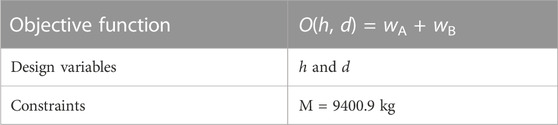
The remaining potential in the structure for the given mass M = 9400.9 kg can be used to reduce the actuation force contribution Nact. As mentioned previously, two different strategies are employed. Strategy n1 seeks to obtain a system with maximum stiffness with respect to wA and wB. This gives the following optimization problem.
The analytical solution yields the following values.
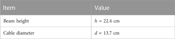
Compared to the previous solution, more material is distributed in the underslung cable, whose stiffness is important to limit wB. The uncontrolled displacements are

which do not satisfy the deflection limits. This is expected because the mass has been kept constant. The previous configuration is the only solution that satisfies the deflection limits without active control. However, the displacement wB has been reduced by 21%. Therefore, the actuation required to eliminate the mid-span displacement, Δl = 0.56 cm, is also smaller. The resulting controlled displacements are
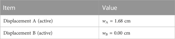
and the actuation force contribution is Nact = −2.73 kN, which is smaller than that required for the previous solution. Nevertheless, this solution is also suboptimal because the displacement wA is over-compensated. The solution can be further improved by explicitly minimizing the actuation force and including the actuator length change in the design variables (strategy n2).
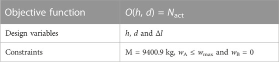
The resulting design is
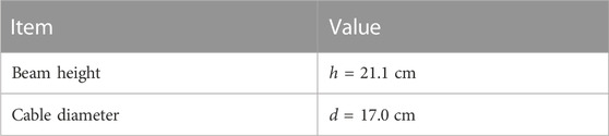
Compared to the previous designs, the diameter of the underslung cable is significantly increased, while the beam becomes more flexible. This has two effects. First, as the underslung structure is stiffer, the displacement wB becomes smaller. Second, as the beam becomes more flexible, the force required for displacement control also becomes smaller. These observations align with the hypothesis formulated at the end of Section 2.2.3. The resulting uncontrolled displacements are

Because the beam is more flexible, the displacement at point A is significantly larger than in previous cases. However, through actuation, the mid-span displacement is eliminated, and point A is also controlled into the target position.

The required actuator length change is Δl = 0.44 cm, and the actuation force contribution is Nact = −1.81 kN. The actuation force is less than half of that required for controlling the mass-optimized passive solution and 24% smaller than that required in the solution produced by strategy n1. The total force in the actuator N = −329.8 kN is also reduced than the other solutions, albeit only marginally. This value cannot change significantly due to the structural configuration of a double-span continuous beam. Section 2.2.3 showed that minimizing the ratio of uncontrolled displacement over the displacement caused by a unit actuation, that is, the flexibility against actuation, gives the same solution as minimizing the actuation force. This is also true for the example discussed in this section. Table 2 gives the results obtained by the two optimization strategies. Strategy n3 results are not given because they are identical to those produced by strategy n2, as shown in Section 2.2.
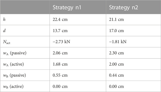
TABLE 2. Underslung beam, optimization results.
3 Numerical investigation of an adaptive ribbed slab
3.1 Problem setup
A square ribbed slab with side length L = 10 m and thickness d, simply supported along all four edges, is considered (Figure 3). There are main and secondary ribs (Figure 4). The height H of the main ribs differs by Δh from the height h of the secondary ribs. All ribs have identical width drib.
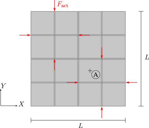
FIGURE 3. Ribbed slab, plan view.
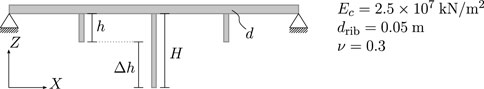
FIGURE 4. Ribbed slab, cross-sectional data.
The two central main ribs divide the plate into four subsections. Each of these subsections is equipped with a pair of secondary ribs. Individual actuation of the secondary ribs is implemented through horizontal forces parallel to the rib axes. These forces can be thought of as generated by an actuator that pulls on a cable embedded in each rib (no bonding) via a duct, as carried out in Reksowardojo et al. (2022). For simplicity, the contribution of the cables to the (passive) stiffness of the structure is neglected. The height h of the secondary ribs equals the eccentricity of the actuation forces Fact (with respect to the plate axis) as they are modeled at the bottom of the secondary ribs. Figure 3 indicates the location of the actuation forces in the plan view for the case of actuation of the upper left and lower right subsections of the slab.
In the following optimization problems, the design variables are the geometry parameters d, h, and Δh, and the actuation force Fact.
Two load cases are considered. Load case 1 is a distributed load on the entire slab (Figure 5). In case 2, only two quarter subsections are loaded (Figure 6). This setup is inspired by a checkerboard-type load case that is considered in building codes for certain scenarios. For example, if the main ribs are relatively stiff, the deflections near the centers of the loaded subsections of the plate are larger for load case 2 than for load case 1.
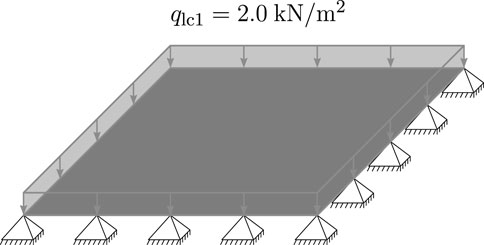
FIGURE 5. Load case 1.
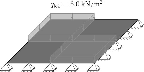
FIGURE 6. Load case 2.
The uncontrolled displacements are constrained to satisfy deflection limits under load case 1. The rationale of this strategy is to have the adaptive system react against only “exceptional” load cases and, second, to work in a design scenario with contrasting stiffness and flexibility requirements. The deflection limit is
3.2 Passive system
A benchmark passive configuration is first obtained that satisfies displacement limits under both load cases without actuation. The optimization has been implemented using the Python package PyAnsys, which enables communication between Python and the commercial finite element software Ansys. A shell element type SHELL181 is employed for the ribs and the slab using a regular mesh of 10 elements along the length L. SHELL181 is a four-node element based on Reissner–Mindlin shell theory (shear deformable). It has been verified through a convergence analysis that the chosen mesh density, in conjunction with reduced integration with hourglass stabilization, provides sufficiently accurate results. The following constrained optimization problems have been solved using sequential least squares programming.
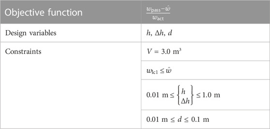
The passive configuration is obtained through volume minimization. Therefore, the objective function is the volume of the entire ribbed slab structure. Constraints include deflection limits for both load cases: wlc1 and wlc2; these values refer to the largest deflections occurring anywhere on the slab for the corresponding load case. The geometric dimensions of the ribs are limited within a certain range for practical applications. The formulation of this optimization problem is

The optimization process yields the following solution.
With this configuration of the ribbed slab, it is possible to satisfy the displacement limits under load case 1 and load case 2 without actuation. The thin plate and ribs can be realized using fiber reinforcement. Potential stability issues are not considered in this simplified linear study.
3.3 Adaptive system
3.3.1 Verification of the above hypothesis on the relation of actuation effort and stiffness
Referring to Section 2.2.3, an analysis is carried out to confirm that minimizing the actuation force is equivalent to minimizing the ratio of the amount by which the displacement limit is violated in the uncontrolled (i.e., passive) state to the displacement caused by a unit actuation,
The objective is to obtain a solution whose volume is reduced to V = 3.0 m3. The displacement limit at point A under load case 1 must be satisfied without actuation. Under load case 2, there is no limit for the uncontrolled state, that is, the displacement limit will be satisfied through actuation.
Strategy n3 (Section 2.2.3), in this case, is formulated as
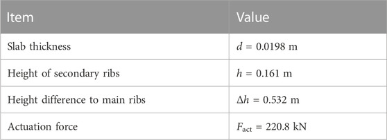
In the objective function, wpass is the uncontrolled displacement under load case 2,

For this configuration, an actuation force Fact = 220.8 kN is required to satisfy the displacement limit
The solution global optimality cannot be guaranteed because the optimization problem has been formulated using a nested analysis and design approach (NAND). However, different starting configurations have been tested, resulting in an identical solution.
Direct minimization of the actuation force has been denoted as strategy n2, which, in this case, is formulated as

Compared to strategy n3, this approach explicitly accounts for both load cases and the actuation force that is the objective function and a design variable simultaneously. The obtained solutions are
Results are identical to those obtained with strategy n3, including the actuation force, confirming the statement given in Section 2.2.
3.3.2 Minimizing compliance vs. minimizing actuation effort
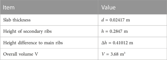
In this section, further analysis is carried out to compare the minimization of the displacement difference
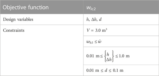
Both load cases are considered; no active control is employed for displacement compensation. As explained in Section 3.2, the maximum displacement is considered, not only the one at point A. The obtained solution is
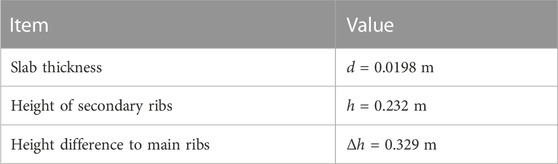
The value of the objective function is wlc2 = 0.0366 m. As expected, this violates the deflection limit of 0.02 m. Satisfying the deflection limit under load case 2 requires an actuation force Fact = 367.9 kN.
For strategy n2, formally, the same optimization problem is obtained as in the previous subsection, repeated here for convenience.
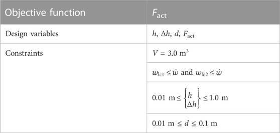
The main difference to the problem stated in Section 3.3.1 is that the maximum displacement is considered and not only that at point A. This is the reason the solution is marginally different.
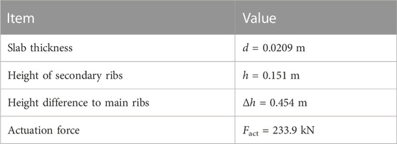
The slab thickness d is almost identical to the one obtained from strategy n1, but the height of the secondary ribs is smaller, while more material is distributed into the main ribs. This causes a larger uncontrolled displacement under load case 2 wlc2 = 0.0464 m. However, it significantly reduces the actuation effort requiring a 36% smaller actuation force. Table 3 gives an overview of the two optimization strategies. Strategy n3 results are not given because, as shown in Section 3.3.1, it produces the same solution as strategy n2.
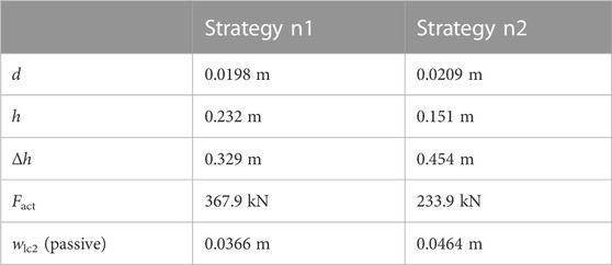
TABLE 3. Ribbed slab, optimization results.
4 Conclusion
The hypothesis that it is an effective strategy to design an adaptive load-bearing structure to be as stiff as possible against external loads and as flexible as possible against actuation actions has been confirmed. Analytical solutions have verified that minimizing the ratio of the amount by which the displacement limit is violated in the uncontrolled state to the displacement caused by a unitary actuation force is identical to minimizing the actuation force. This means that, as an alternative to formally solving a mathematical optimization problem to minimize actuation effort, which is a complex task, some combination of stiffness versus load and flexibility versus actuation can be pursued as the engineering rationale for designing adaptive structures.
The value of the numerical examples formulated in this work lies not in providing feasible designs that can be fabricated but in providing intuitive yet analytically verified evidence that a trade-off between stiffness and flexibility is the key to efficient adaptive structure design. When designing adaptive versus conventional passive structures, the goals are different. This study confirms previous findings that designing adaptive structures requires a holistic, systemic approach as opposed to maximizing the stiffness and then reducing displacements actively under strong loading.
Data availability statement
The original contributions presented in the study are included in the article and the Supplementary Material; further inquiries can be directed to the corresponding author.
Author contributions
AT, TP, and MB wrote the first draft of the manuscript. GS contributed extensively through revision, and LB reviewed the revised manuscript. GS and LB also contributed to the basic concept of adaptive ribbed slabs. Moreover, GS, LB, and MB were responsible for the research strategy and direction. MB derived the analytical solutions reported in Section 2; TP contributed to the basic setups of the analytical case studies. AT performed the numerical studies in Section 3. All authors contributed to the article and approved the submitted version.
Funding
This work has been carried out in the framework of the Collaborative Research Center 1244 “Adaptive Skins and Structures for the Built Environment of Tomorrow” within the projects A04, “Form finding, structural optimization, and system optimization,” and B01, “Characterization, modeling, and model order reduction,” funded by the Deutsche Forschungsgemeinschaft (DFG, German Research Foundation) under project number 279064222. The authors are grateful for the generous support.
Conflict of interest
The authors declare that the research was conducted in the absence of any commercial or financial relationships that could be construed as a potential conflict of interest.
Publisher’s note
All claims expressed in this article are solely those of the authors and do not necessarily represent those of their affiliated organizations, or those of the publisher, the editors, and the reviewers. Any product that may be evaluated in this article, or claim that may be made by its manufacturer, is not guaranteed or endorsed by the publisher.
Supplementary material
The Supplementary Material for this article can be found online at: https://www.frontiersin.org/articles/10.3389/fbuil.2023.1135117/full#supplementary-material
References
Adam, B., and Smith, I. F. (2008). Active tensegrity: A control framework for an adaptive civil-engineering structure. Comput. Struct. 86, 2215–2223. doi:10.1016/j.compstruc.2008.05.006
Blandini, L., Haase, W., Weidner, S., Böhm, M., Burghardt, T., Roth, D., et al. (2022). D1244: Design and construction of the first adaptive high-rise experimental building. Front. Built Environ. 8, 814911. doi:10.3389/fbuil.2022.814911
Bleicher, A., Schlaich, M., Fujino, Y., and Schauer, T. (2011). Model-based design and experimental validation of active vibration control for a stress ribbon bridge using pneumatic muscle actuators. Eng. Struct. 33, 2237–2247. doi:10.1016/j.engstruct.2011.02.035
Domke, H. (1992). Aktive tragwerke. Wiesbaden: VS Verlag für Sozialwissenschaften. doi:10.1007/978-3-322-85350-9
Geiger, F., Gade, J., von Scheven, M., and Bischoff, M. (2020a). A case study on design and optimization of adaptive civil structures. Front. Built Environ. 6, 94. doi:10.3389/fbuil.2020.00094
Geiger, F., Gade, J., von Scheven, M., and Bischoff, M. (2020b). Optimal design of adaptive structures vs. Optimal adaption of structural design. IFAC-PapersOnLine 53, 8363–8369. doi:10.1016/j.ifacol.2020.12.1604
Kelleter, C., Burghardt, T., Binz, H., Blandini, L., and Sobek, W. (2020). Adaptive concrete beams equipped with integrated fluidic actuators. Front. Built Environ. 6, 91. doi:10.3389/fbuil.2020.00091
Korkmaz, S. (2011). A review of active structural control: Challenges for engineering informatics. Comput. Struct. 89, 2113–2132. doi:10.1016/j.compstruc.2011.07.010
Neuhäuser, S., Haase, W., Weickgenannt, M., and Sawodny, O. (2013). Adaptive Tragwerke – aktuelle Forschungen im Ultraleichtbau. Stahlbau 82, 428–437. doi:10.1002/stab.201310057
Reinhorn, A., Soong, T., Riley, M., Lin, R., Aizawa, S., and Higashino, M. (1993). Full-scale implementation of active control. II: Installation and performance. J. Struct. Eng. 119, 1935–1960. doi:10.1061/(asce)0733-9445(1993)119:6(1935)
Reksowardojo, A. P., Senatore, G., Blandini, L., and Bischoff, M. (2022). “Vibration control of simply supported beam bridges equipped with an underdeck adaptive tensioning system,” in Bridges and structures: Connection, integration and harmonisation (Zürich, Switzerland: IABSE Congress Nanjing), 539–548. doi:10.2749/nanjing.2022.0539
Schwegmann, L. (2022). “Adaptive systems: An overview and some research results,” in Active and passive smart structures and integrated systems XVI. Editors J.-H. Han, S. Shahab, and J. Yang (Bellingham, Washington: International Society for Optics and Photonics), 12043. doi:10.1117/12.2619724
Senatore, G., Duffour, P., Hanna, S., Labbe, F., and Winslow, P. (2011). Adaptive structures for whole life energy savings. J. Int. Assoc. Shell Spatial Struct. 52, 233–240. doi:10.5281/zenodo.7944437
Senatore, G., Duffour, P., and Winslow, P. (2019). Synthesis of minimum energy adaptive structures. Struct. Multidiscip. Optim. 60, 849–877. doi:10.1007/s00158-019-02224-8
Senatore, G., Duffour, P., Winslow, P., and Wise, C. (2017). Shape control and whole-life energy assessment of an ‘infinitely stiff’ prototype adaptive structure. Smart Mater. Struct. 27, 015022. doi:10.1088/1361-665X/aa8cb8
Sobek, W., and Teuffel, P. (2001). “Adaptive systems in architecture and structural engineering,” in Smart structures and materials 2001: Smart systems for bridges, structures, and highways (SPIE) (Bellingham, Washington: International Society for Optics and Photonics), 4330, 36–45. doi:10.1117/12.434141
Soong, T. (1988). State–of–the–art review: Active structural control in civil engineering. Eng. Struct. – Eng. Struct. 10, 74–84. doi:10.1016/0141-0296(88)90033-8
Teuffel, P. (2004). Entwerfen adaptiver Strukturen – lastpfadmanagement zur Optimierung tragender Leichtbaustrukturen. Ph.D. thesis (Universität Stuttgart: Institut für Leichtbau Entwerfen und Konstruieren). doi:10.18419/opus-195
Utku, S. (1998). Theory of adaptive structures: Incorporating intelligence into engineered products. Boca Raton: CRC Press. 18 of New Directions in Civil Engineering. doi:10.1201/9780203719015
Wada, B. K. (1990). Adaptive structures - an overview. J. Spacecr. Rockets 27, 330–337. doi:10.2514/3.26144
Wang, Y., and Senatore, G. (2021). Design of adaptive structures through energy minimization: Extension to tensegrity. Struct. Multidiscip. Optim. 64, 1079–1110. doi:10.1007/s00158-021-02899-y
Wang, Y., and Senatore, G. (2020). Minimum energy adaptive structures – all-In-One problem formulation. Comput. Struct. 236, 106266. doi:10.1016/j.compstruc.2020.106266
Keywords: adaptive structures, optimization, mass reduction, actuators, displacement control
Citation: Trautwein A, Prokosch T, Senatore G, Blandini L and Bischoff M (2023) Analytical and numerical case studies on tailoring stiffness for the design of structures with displacement control. Front. Built Environ. 9:1135117. doi: 10.3389/fbuil.2023.1135117
Received: 31 December 2022; Accepted: 01 May 2023;
Published: 24 May 2023.
Edited by:
Marios C. Phocas, University of Cyprus, CyprusReviewed by:
Anders Eriksson, Royal Institute of Technology, SwedenStefanos Gkatzogiannis, National Technical University of Athens, Greece
Copyright © 2023 Trautwein, Prokosch, Senatore, Blandini and Bischoff. This is an open-access article distributed under the terms of the Creative Commons Attribution License (CC BY). The use, distribution or reproduction in other forums is permitted, provided the original author(s) and the copyright owner(s) are credited and that the original publication in this journal is cited, in accordance with accepted academic practice. No use, distribution or reproduction is permitted which does not comply with these terms.
*Correspondence: Axel Trautwein, dHJhdXR3ZWluQGliYi51bmktc3R1dHRnYXJ0LmRl