Abstract
Sedimentary processes often produce natural and blown calcareous sands that are deposited in inclined and layered formations. These calcareous sands frequently exist in a complex stress state with rotating principal stress axes that result in intricate mechanical properties. To investigate the mechanical behaviors of calcareous sands with inclined sedimentary surfaces, we developed a device to prepare hollow cylindrical specimens from artificially crushed calcareous sands. By combining this device with a hollow cylindrical torsional shear apparatus, undrained monotonic loading and pure principal stress rotation tests were conducted to investigate the static and dynamic properties of the inherently anisotropic calcareous sands. The results indicate that the shear dilatancy property is related to the principal stress direction; the shear dilatancy of calcareous sand decreases as the direction of the principal stress increases, and the peak stress ratio decreases with increasing principal stress direction and increases with increasing deposition direction. In the precyclic loading period, increases in the deposition direction led to increases in the stabilities of the specimens and decreases in excess pore pressure accumulation, which further affect the dynamic shear modulus and damping ratio of the calcareous sand. In the late stage of cyclic loading, the inherent anisotropies of the specimens are destroyed, so that the excess pressure and hysteresis loop characteristics start to converge.
1 Introduction
Calcareous sand is widely distributed near coral reefs and is an important material used in island geotechnical engineering constructions. Site investigations have shown that natural calcareous sand is sedimented in accordance with the local seafloor topography. The sedimentation features along with horizontal, monoclinal, diapiric, and other complex geological structures are affected by the characteristics of the marine environment, such as winds, waves, and tides. Although this type of stratified sediment is common, very few studies are available in literature regarding the effects of various phenomena on the mechanical characteristics of calcareous sands, which have resulted in problems with ocean engineering constructions and exploitation of marine resources.
There are many feasible methods available for coring and cutting along different directions with regard to specimen preparations of stratified rocks and clays as they possess self-stabilizing abilities (Deng et al., 2018). Figure 1 illustrates the typical coring orientations of inclined specimens, in which the angle values are determined on the basis of the deposition surface and end face; these allow subsequent study of the effects of the sedimentation direction on the mechanical properties of the material. Diyuan et al. (2012) found that the triaxial compressive strengths of transversely laminated rock specimens were higher than those of longitudinally laminated rock specimens under identical circumferential pressure conditions. Ghazvinian et al. (2013) studied the shear characteristics of greenschists with different bedding angles under different loading directions through the oblique shear test; they found that the shear strength and failure mechanism of the specimen were affected by the laminar inclination angle and loading direction. Jia et al. (2013) conducted simple shear and triaxial tests and concluded that the strength of the layered shale first decreased and then increased with increase in the bedding plane dip angle. Deng et al. (2018) studied the bedding effects of sandstones on their mechanical characteristics and failure models; they concluded that the bedding angle of the sandstone dominates its strength, apparent cohesion, internal friction angle, and failure model. Yuan and Yang (1996) and Salager et al. (2013) studied the mechanical behaviors of clay for depositional dips of 0°, 45°, and 90°. Their results show that specimens with 0° depositional dip exhibit great stretchability, specimens with 90° depositional dip have higher stiffness values, and specimens with 45° depositional dip have the lowest strengths. Wichtmann and Triantafyllidis (2018) analyzed the effects of the stratification planes on the mechanical behaviors of kaolin clays and noted that specimens that are cut horizontally have greater dilatancies and higher strengths.
FIGURE 1

Diagram showing the cutting directions of the inclined specimens (Deng et al., 2018).
The sand specimens in the laboratory tests were mostly made from remolded samples as they cannot stabilize by themselves owing to low cohesion. The common methods used to prepare the sand specimens can be categorized as follows: vibration, compaction, ramming, and sand rain (Ministry of Housing and Urban Rural Development of the People’s Republic of China). The sand rain method used to prepare the sand specimens depends mainly on the gravity of the sand particles, which further influences the horizontal depositional surface. To prepare sand specimens with inclined depositional surfaces, the preparation mold was placed inside a specimen-making mold to achieve a specific angle ζ (Figure 2). Thereafter, the sand particles were sprinkled over the specimen-making mold in accordance with the guidelines of the sand rain method. Thus, sand specimens with inclined depositional angles of ζ were obtained. Guo (2008), Tong et al. (2014), and Afzali-Nejad et al. (2018) obtained different internal friction angles and dilatancy angles against the dip angles through direct shearing tests on the sand specimens with inclined depositional angles. Based on a series of laboratory triaxial tests on sand specimens with inclined depositional angles, various researchers (Lam and Tatsuoka, 1988; Tang et al., 2021; Zamanian et al., 2020, 2021) found that sand has significant anisotropy and that its shear strength tends to decrease with increase in ζ. Rodriguez and Lade (2013) performed true triaxial tests on sand specimens with inclined depositional angles and showed that the inclined angles and intermediate principal stress parameter have significant effects on the deformation and strength characteristics of anisotropic sands.
FIGURE 2

Diagram showing the inclined sand rain method.
Only the effects of the depositional direction on the behavior of sand were accounted for in the aforementioned studies, while the loading direction was maintained constant during testing. However, it has been widely reported in literature that marine environmental loads, such as wave loads and earthquakes, result in obvious rotation of the principal stress axis (Zhu et al., 2020; Zamanian and Jafarzadeh, 2020; Chaudhary et al., 2002). This has significant effects on the mechanical characteristics of geotechnical materials, such as their strength, deformation, and pore pressure (Tong et al., 2021; Zdravković and Jardine, 2001; Sivathayalan and Vaid, 2011). Accordingly, a new testing method must be developed to study the mechanical behaviors of inclined sedimentary sands under the principal stress rotation. To address this gap, we developed a specimen preparation method for hollow cylindrical tests of sand samples with inclined sedimentary surfaces based on the principle of the hollow cylindrical torsional shear instrument; accordingly, reshaped calcareous sand specimens can be prepared in the laboratory for monotonic and cyclic loading tests of samples with inclined sedimentary surfaces. The main feature of this method is that it enables study of the static and dynamic mechanical behaviors of calcareous sands with inclined sedimentary surfaces even when the stress loading direction changes.
2 Hollow cylindrical torsional shear apparatus
2.1 Introduction of the instrument
The hollow cylindrical torsional shear apparatus (HCA) is an ideal instrument for studying the soil mechanical behaviors under the principal stress rotation condition and is especially appropriate for the static and quasistatic cases. The apparatus used in this study is the GDS HCA, as shown in Figure 3, which includes the pressure chamber, axial torsional loading control system, external pressure controller, internal pressure controller, back pressure controller, and data control and collection system. The apparatus can exert a maximum axial force of 10 kN with an accuracy of 0.01 kN, has a measuring range of axial displacements between −20 mm and 60 mm with an accuracy of 0.001 mm, apply a maximum torque of 100 Nm with an accuracy of 0.1 Nm, and has an unlimited torsion angle with an accuracy of 0.1°.
FIGURE 3

Photograph of the GDS hollow cylindrical torsional shear test system.
2.2 Loading laws
The HCA system was used to prepare the sand specimen with the stress state shown in Figure 4 by exerting an axial load W, a torsional load MT, an internal pressure , and an external pressure . Accordingly, the sand element is subjected to an axial stress , a radial stress , a circumferential stress , and a shear stress in the polar coordinate system, which render a maximum principal stress of and minor principal stress of deflecting around the middle principal stress of (Liu et al., 2005; Yang et al., 2006; Dong et al., 2017). Thus, by applying , , , and to the soil element in the cylindrical system, we can realize maximum and minor principal stress rotations around the middle principal stress in the principal stress coordinate system.
FIGURE 4

Stress state of the hollow cylindrical specimen.
3 Preparation of the soil specimen
3.1 Principle of specimen preparation
The resultant forces on the sand particles determine the casting and deposition directions during sand rain preparation. The gravitational force causes the sand particles to fall vertically to form a horizontal sedimentary surface that is always parallel to the secondary principal stress direction; this means that the stress state of the specimen rotates only around the secondary principal stress axis. With reference to the methods used to prepare the rock and clay specimens, rotation of the stress state around the secondary principal stress axis can be realized using specimens with directional deposition surfaces. To better analyze the obtained data, the slope angle of the specimen’s sedimentary surface must be independent of the stress rotational angle. Considering that the radial stress direction is fixed during the loading of the hollow cylindrical torsional shear test, a viable method would be to prepare a sand specimen with an inclined sedimentary surface first and then ensure that the stress rotates about the radial direction using the torsional shearing apparatus. Thus, we can control the stress direction from two aspects, i.e., the specimen and the stress.
To prepare sand specimens with specific sedimentary surfaces, it is necessary to control the resultant forces of the particles along the radial oblique inward or outward direction during specimen preparation. Considering that gravity is an objective force in the downward direction, an inclined resultant force can be obtained by exerting a horizontal force on the sand particles. Moreover, the centrifugal force has a horizontal, controllable, and radially symmetric nature. Accordingly, we developed a special specimen preparation system capable of producing sand specimens with specific inclined sedimentary surfaces by rotating the hollow cylindrical specimen-making mold at high speeds to generate centrifugal forces (Dong et al., 2022).
3.2 Method for preparing the sand specimen
As shown in Figure 5, the sand particles are subjected to the vertical gravitational force G and horizontal centrifugal force F during sprinkling:where m is the mass, g is the gravitational acceleration, r is the rotating radius, and ω is the angular velocity. Then, the intersection angle between the resultant and gravitational forces is given by
FIGURE 5
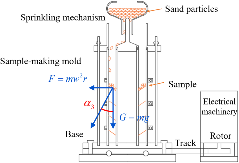
Specimen preparation principle for the inclined hollow cylindrical sand specimen.
where ω is governed as
Considering that
the rotational speed is obtained aswhere is the angle of rotation around the third principal stress.
The relationship between rotational speed and inclination angle α3 can be determined by Equations 1–6. Among them, the average radius r = 40 mm (inner and outer radii of the specimen are 30 mm and 50 mm, respectively) is used to calculate the rotational speed for convenience. Table 1 shows the parameters for the inclined specimen. It is seen that the sedimentary dip increases linearly with the rotational speed. For n = 0 r/min, = 0°. When the rotational speed is 149.55 r/min, i.e., when the corresponding sedimentary dip is equal to 45°, the sensitivity of the sedimentary dip to the rotational speed tends to decrease. Owing to the presence of trigonometric functions in both equations, the sedimentary angle can only approach 90° but never reach 90° as the rotational speed increases continuously.
TABLE 1
| Radius r (mm) | Gravitational acceleration g (m∙s-2) | Sedimentary dip α3 (°) |
Circular velocity Ω (° s-1) |
Rotational speed n (r∙min-1) |
|---|---|---|---|---|
| 40 | 9.81 | 0 | 0.00 | 0.00 |
| 15 | 464.47 | 77.41 | ||
| 22.5 | 577.49 | 96.25 | ||
| 30 | 681.79 | 113.63 | ||
| 45 | 897.28 | 149.55 | ||
| 60 | 1,180.88 | 196.81 | ||
| 67.5 | 1,394.14 | 232.36 | ||
| 75 | 1,733.33 | 288.89 | ||
| 85 | 3,032.88 | 505.48 |
Parameters used in the preparation of the inclined specimens.
3.3 Effectiveness and reproducibility of sample preparation
To verify the effectiveness and reproducibility of the sampling method in this paper, a series of mixed samples of quicklime and colored sand were prepared. Figure 6 shows some cross sections of samples with a deposition direction of = 45°, and it is seen that the inclinations of the deposition surfaces of the two specimens are nearly 45°, with the maximum difference in angle being 2°. This shows that the proposed sampling method can help realize the preparation of specimens with inclined sedimentary surfaces. In addition, the prepared specimens are inevitably sorted owing to the influences of particle quality and horizontal distance. Overall, the proposed method has good sampling effectiveness and high reproducibility.
FIGURE 6

Cross sections showing sand rain samples for the deposition direction = 45°.
4 Testing method and results
4.1 Testing method
The calcareous sand used in this study was sourced from the Philippines and was crushed artificially. The particle grading curve of the artificially crushed calcareous sand (ACCS) is shown in Figure 7, which indicates that the particle sizes of the crushed sand are relatively uniform between 0.1 mm and 1 mm. The basic physical properties of the ACCS were measured and are shown in Table 2. The specific gravity of the sand was 2.75, and the maximum and minimum dry densities were 1.519 and 1.325 g/mm3 that allowed the maximum and minimum pore ratios to be calculated as 1.08 and 0.81, respectively. Moreover, the ACCS has a coefficient of uniformity of 2.54, curvature coefficient of 1.03, and mean particle size of 0.42.
FIGURE 7

Particle gradation curve of the artificially crushed calcareous sand (ACCS).
TABLE 2
| Parameter | Value |
|---|---|
| Specific gravity | 2.75 |
| Maximum dry density d max (g/mm3) | 1.519 |
| Minimum dry density d min(g/mm3) | 1.325 |
| Coefficient of uniformity | 2.54 |
| Curvature coefficient | 1.03 |
| Mean particle size d50 (mm) | 0.42 |
Physical property parameters of the ACCS.
Because of the friable nature of calcareous sand, it is necessary that the new sampling method considers the problem of particle crushing during the sampling process. In fact, crushing of calcareous sand particles requires a critical crushing pressure that is greater than the particle strength of the sample itself. During the sample preparation process, only centrifugal and gravitational forces act on the calcareous sand particles, that is, there is no strong load during the sample preparation process. Moreover, particle breakage was not observed during the entire sample preparation process, so the particle crushing problem can be ignored. The prepared specimen of ACCS is shown in Figure 8. The vibration method was used to control the relative density , but as the sample-making mold is constantly rotating during sample preparation, we can only control the relative density to between 50% and 65%. As shown in Table 3, the relative density was about 51% for the monotonic experiment and 64% for the pure principal stress rotation test. The relative compactness of specimens with different deposition surface inclinations varies slightly owing to the rotational speed, vibration, and eccentricity of the instrument, as well as the rubber membrane adhering to the wall. However, the differences in relative density among different specimens are within 5% and differences in mass are within 10g considering the maximum and minimum dry densities of the calcareous sand used in this paper. Therefore, good control of the relative density can be realized, which also shows that the experiment is repeatable.
FIGURE 8

Prepared specimen using ACCS.
TABLE 3
| Test | /(°) | /(°) | /(%) | /(kPa) | Loading |
|---|---|---|---|---|---|
| M00-00 | 0 | 0 | 49.5 | 50 | q = 3kPa/min |
| M00-15 | 0 | 15 | 52.4 | 50 | |
| M00-30 | 0 | 30 | 52.9 | 50 | |
| M00-45 | 0 | 45 | 53.2 | 50 | |
| M15-00 | 15 | 0 | 48.5 | 50 | |
| M30-00 | 30 | 0 | 50.8 | 50 | |
| M45-00 | 45 | 0 | 53.4 | 50 | |
| R00-00 | 0 | 0–180 | 63.7 | 50 |
= 0.9 f = 1Hz |
| R15-00 | 15 | 0–180 | 64.7 | 50 | |
| R30-00 | 30 | 0–180 | 65.7 | 50 | |
| R45-00 | 45 | 0–180 | 63.1 | 50 |
Details of the undrained shearing tests.
Saturation and consolidation were started immediately after installing the sample in the pressure chamber. The first step in the saturation process is to pass carbon dioxide (CO2) through the specimen and then through the airless water to replace any air in the specimen. Thus, the sand reached full saturation at an effective pressure of 20 kPa and a back pressure of 200 kPa. The tested Skempton B parameters were all greater than 0.95. Next, the specimens were consolidated to an effective stress of 50 kPa and monotonic loading tests were performed using isotropic consolidation. However, the pure principal stress rotation test requires the bias stress q to be loaded to a certain value before anisotropic consolidation is carried out under the condition of this q certain value.
Considering that inclined calcareous sands are usually under the influences of buildings or wave loads, two stress paths are designed in this paper, namely monotonic loading and pure principal stress rotation. Both these tests were performed under undrained conditions, and all tests were conducted at an effective confining pressure of = 50 kPa. The coefficient of the middle principal stress b is in the tests so that the inner pressure of the specimen is equal to its outer pressure. Initially, seven sets of monotonic loading tests (M-series) were conducted with a loading rate of q = 3 kPa/min for different deposition directions and principal stress directions , where and were set to 0°, 15°, 30°, and 45°. Thereafter, pure principal stress rotation tests (R-series) were performed on the specimens with deposition directions of 0°, 15°, 30°, and 45° with the cyclic stress ratio (CSR) = 0.9 and frequency f = 1 Hz. The details of these tests are listed in Table 3.
4.2 Monotonic loading test results
Figure 9 shows the monotonic responses of calcareous sand for various principal stress directions and deposition directions . The effective stress paths are plotted in the deviatoric stress q versus effective confining pressure p′ coordinate system, and it can be seen that the calcareous sand always exhibits shear dilatancy when the principal stress direction coincides with the deposition direction ( = 0°, = 0°). Although there is no phase transition, the effective stress path exhibits a turn similar to the phase transition phenomenon (marked with the black circles in Figure 9), which will continue to be referred to as the phase transition point in this paper. As deviates from (i.e., when is 0° and varies from 0° to 45°), the phase transition point in the effective stress path gradually shifts to the left. The phase transition then occurs at = 45°, and the calcareous sand specimen is under not only shear expansion but also shear shrinkage followed by shear dilatancy. Consequently, the shear dilatancy property of the calcareous sand is weakened with increasing while the shear shrinkage property is enhanced. In contrast, under the condition of changing (i.e., when = 0° and varies from 0° to 45°), there is no significant change in the shear dilatancy of calcareous sand at = 50 kPa. In addition, the phase transition points are labeled in the excess pore pressure and stress–strain curves. It is found that the excess pore pressure at the phase transition point changes from negative to positive with increasing , while changes in have no effect on it, which verifies the relationships of the shear dilatancy property of calcareous sand to the principal stress direction and deposition direction . It is also observed from the stress–strain curve that the generalized shear strain at phase transition is less than 0.5%, and that the stress ratios are essentially around 1.0 except for = 45°.
FIGURE 9

The monotonic loading test results of specimens with different stress directions α2=0-45° and deposition directions α3=0-45°.
In most cases, the stress ratio increases and then decreases with increases in the generalized shear strain , and the calcareous sand specimens exhibit strain hardening. However, at = 45°, the stress ratio initially increases to the peak point and remains steady; it is then followed by a steep decrease and finally stabilizes again. The peak stress ratios of each test are labeled in Figure 9, where the stress ratio before the steep drop is taken as for tests with = 45°. It is observed that decreases with increasing , in contrast to that increases with increasing . The of specimens with different corresponded to in the range of 6%–7% and those with different have in the range of 4%–7%. Moreover, the specimen strength q corresponding to decreases while the excess pore pressure increases with increase in . However, there are no obvious patterns of q and corresponding to under different . Notably, the values for different are oriented in a straight line in the q-p′ graph and are distributed in the effective stress path with = 0°.
A comprehensive comparison of the test results reveals that the strain of the calcareous sand specimen develops at an accelerated rate after phase transformation. In addition to strain development, the pore pressure dissipates rapidly, but there are differences in the pore pressure dissipation rates under different principal stress directions and deposition directions . Furthermore, once the stress ratio reaches the peak point, the strain development is accelerated further, and the specimen is destroyed in a short period of time thereafter. However, the pore pressure dissipation rate slows and tends to a certain value. The final excess pore pressure value varies depending on the principal stress direction but not on the deposition direction . More importantly, the stronger the shear dilatancy, the higher is the strength and smaller is the strain produced at the same deviatoric stress q. Therefore, it can be reasonably assumed that the principal stress direction and deposition direction affect the shear dilatancy property of calcareous sand and also its mechanical properties by influencing the particle arrangement. Among these, the deposition direction determines the initial particle arrangement while the principal stress direction determines the particle movement law during the shear process.
4.3 Pure principal stress rotation test results
A series of undrained pure principal stress rotation tests were conducted on calcareous sand specimens with deposition directions of 0°, 15°, 30°, and 45°. The effects of the inherent anisotropy on the cyclic properties of calcareous sand were investigated from the perspectives of strain, pore pressure, and shear stress–strain relationship. Figure 10 illustrates the relationship curves between the strain components and number of cycles N (for the first 1,000 cycles) for specimens with different when the compressive strain is positive. Figure 10A demonstrates the effects of the deposition direction on the developmental pattern of the axial strain , which is dominated by compression. Because the CSR is large ( = 0.9), the specimen does not exhibit full elasticity and instead shows plastic accumulation. The develops rapidly to about 1% in the early stage of cycling (first 20 cycles), and the strain development rate slows as N increases. The radial strain and circumferential strain are expansive and develop in similar patterns to that of axial strain . It is noteworthy that the magnitudes of and are about half of that of , where is slightly larger than . Moreover, strain development is dependent on . When the CSR is fixed, as increases, the strain in the calcareous sand decreases for the same number of cycles (except at = 45°). This suggests that an appropriate deposition angle is helpful for improving the stability of calcareous sand.
FIGURE 10

Strain components of specimens with different deposition directions α3=0-45°.10 (A): Axial strain εz.10 (B):Radial strain εr.10 (C): Circumferential strain εθ.
Figure 11 shows the development pattern of the excess pore pressure for different under the pure principal stress rotation conditions. Similar to strain development, the excess pore pressure accumulates rapidly over the first 20 cycles. It is worth noting that there are peaks in the excess pore pressure curves at = 0° and 15°, i.e., first accumulates to a maximum value and then decreases gradually, whereas there are no peaks at = 30° and 45°. Among these, the peak is 30 kPa when = 0° and 23 kPa when = 15°. After 100 cycles, all tests enter the stable fluctuation stage; however, regardless of the changes in , fluctuated in the vicinity of 20 kPa at the final stabilization stage, with a fluctuation amplitude of 2 kPa. The fluctuation magnitude of decreases gradually with increasing in the early stage, and has no effect on in the later stage of cycling.
FIGURE 11

Excess pore pressures of specimens with different deposition directions.
Figure 12 presents the shear stress–strain relationship for different . It can be observed that the shear stress–strain curves for different develop with the same patterns under dynamic loading and show hysteresis characteristics; the hysteresis loop moves to the left as the number of cycles increases. However, the moving speed of the loops decreases gradually for values other than = 0° but increases and then decreases at = 0°. After about 20 cycles, the hysteresis loops are close to overlapping with each other and become invisible due to overcrowding. It is demonstrated that under a small confining pressure (50 kPa) and large CSR (0.9), the anisotropic consolidated specimen produces a greater shear deformation at the beginning of the cycle, after which it enters the plastic creep state. In addition, the shear strain in the plastic creep stage decreases gradually with increasing . This implies that has an important effect on the deformation resistance of calcareous sand under pure principal stress rotation.
FIGURE 12

Shear stress–strain relationship of specimens with different deposition directions.
To better observe the effects of the number of cycles and on the hysteresis loop, the hysteresis loops for N = 1, 10, 100, and 1,000 are plotted individually, as shown in Figure 13. In the first cycle, the hysteresis loop is not closed, which means that the specimen has developed plastic deformation. As the number of cycles increases, the degree of opening of the hysteresis loop decreases gradually, and the specimen shows mainly viscoelastic deformation within one cycle. Furthermore, the number of cycles required for the specimen to produce the same shear strain increase exponentially. More importantly, with the increase in the number of cycles, the slope of the hysteresis loop (dynamic shear modulus) decreases first and then increases, while the area (damping ratio) increases first and then decreases. The stiffness values of the specimens does not decay further but increases slightly. The slope increases gradually and the area decreases with increasing for the same number of cycles. When the number of cycles is 1,000, the specimens with different values have approximate slopes and areas. It is thus shown that the hysteresis loop is not affected by and number of cycles during the plastic creep phase.
FIGURE 13

Hysteresis loops of specimens with different deposition directions.
As mentioned above, under larger CSR values (0.9), the calcareous sand strains develop rapidly in the precyclic phase, inducing excess pore pressure accumulation, which further affects the dynamic shear modulus and damping ratio. Owing to anisotropic consolidation, the calcareous sand enters the plastic creep state and stabilization of the dynamic properties in the later stages of the experiment. The deposition direction also affects the dynamic properties of calcareous sand in the early stages, and the particle orientation is an intrinsic factor. The more the particle orientation tends to be horizontal, the less are the intergranular contact and friction during cyclic loading, which lead to lower overall stiffness and stability of the calcareous sand specimens. However, when the specimen enters the plastic creep state, the initial particle arrangement is destroyed and the particle orientation tends to be isotropic, resulting in similar dynamic properties.
5 Conclusion
Based on the proposed method of preparing sand specimens and the principle of the specimen loading equipment, a new device was developed to prepare hollow cylindrical specimens of inclined sand. Hollow cylindrical calcareous sand specimens with rotating sedimentary surfaces about the radial orientation were prepared by controlling the direction of the resultant forces of particles in the sand rain method. The relationship between the centrifugal and gravitational forces was derived to quantitatively control the deposition direction of the hollow cylindrical specimen. The inclined sedimentary dip of the sand specimen can be quantitatively controlled through the rotational speed of the equipment, which lays the foundation for the corresponding tests.
Monotonic shear tests were carried out on the calcareous sand specimens under different principal stress directions and deposition directions . It was found that the shear dilatancy property of calcareous sand was mainly affected by the principal stress direction . The peak stress ratio was closely related to both the principal stress direction and deposition direction . Pure principal stress rotation tests showed that the dynamic properties like strain, excess pore pressure, and shear stress–strain relationship were dependent on the deposition direction . In particular, the strain, excess pore pressure, and damping ratio decrease with increase in in the early stage, while the dynamic shear modulus increases. However, the specimen enters the plastic creep stage during the later stage, where the excess pore pressure and hysteresis loop characteristics become consistent and independent of the deposition direction . Generally, the deposition direction changes the orientations of the particles in the specimen, i.e., the inherent anisotropy varies, which further affects the static and dynamic properties of calcareous sand.
Statements
Data availability statement
The original contributions presented in the study are included in the article/supplementary material; further inquiries can be directed to the corresponding author.
Author contributions
YA: writing–original draft and writing–review and editing. HL: writing–review and editing. TD: writing–review and editing. CL: writing–review and editing. MZ: writing–review and editing.
Funding
The authors declare that financial support was received for the research, authorship, and/or publication of this article. This research was financially supported by the project funded by China Postdoctoral Science Foundation (no. BX2021115) and National Natural Science Foundation of China (no. 51909268).
Conflict of interest
The authors declare that the research was conducted in the absence of any commercial or financial relationships that could be construed as a potential conflict of interest.
Publisher’s note
All claims expressed in this article are solely those of the authors and do not necessarily represent those of their affiliated organizations, or those of the publisher, the editors, and the reviewers. Any product that may be evaluated in this article, or claim that may be made by its manufacturer, is not guaranteed or endorsed by the publisher.
References
1
Afzali-Nejad A. Ali L. Farhadi B. (2018). Role of soil inherent anisotropy in peak friction and maximum dilation angles of four sand-geosynthetic interfaces. Geotext. Geomembranes46 (6), 869–881. 10.1016/j.geotexmem.2018.08.003
2
Chaudhary S. K. Kuwano J. Hashimoto S. Hayano Y. Nakamurai Y. (2002). Effects of initial fabric and shearing direction on cyclic deformation characteristics of sand. Solis Found.42 (1), 147–157. 10.3208/sandf.42.147
3
Deng H. Wang W. Jianlin L. Zhang Y. Zhang X. et al (2018). Experimental study on anisotropic characteristics of bedded sandstone. Chin. J. Rock Mech. Eng.37 (1), 112–120. (in Chinese). 10.13722/j.cnki.jrme.2017.1205
4
Diyuan L. Wong N. Liu G. Zhang X. (2012). Influence of water content and anisotropy on the strength and deformability of low porosity meta-sedimentary rocks under triaxial compression. Eng. Geol.126, 46–66. 10.1016/j.enggeo.2011.12.009
5
Dong T. Liu C. Fang Y. Wang Y. An Y. et al (2022). Preparation method of hollow cylindrical specimen of inclined sedimentary sand. Chin. J. Geotechnical Eng.S2, 3551–3558. 10.13722/j.cnki.jrme.2022.0102
6
Dong T. Zheng Y. Liang K. Mei Z. et al (2017). Control and realization of generalized stress paths in HCA test. Chin. J. Geotechnical Eng.39 (S1), 106–110. (in Chinese).
7
Ghazvinian A. Vaneghi R. G. Hadei M. R. Azinfar M. (2013). Shear behavior of inherently anisotropic rocks. Int. J. Rock Mech. Min. Sci.61, 96–110. 10.1016/j.ijrmms.2013.01.009
8
Guo P. (2008). Modified direct shear test for anisotropic strength of sand. J. Geotechnical Geoenvironmental Eng.134 (9), 1311–1318. 10.1061/(asce)1090-0241(2008)134:9(1311)
9
Jia C. Chen J. Guo Y. Yang C. Wang L. et al (2013). Research on mechanical behaviors and failure modes of layer shale. Rock Soil Mech.34 (S2), 57–61. (in Chinese). 10.16285/j.rsm.2013.s2.006
10
Lam W.-K. Tatsuoka F. (1988). Effects of initial anisotropic fabric and σ2 on strength and deformation characteristics of sand. Soils Found.28 (1), 89–106. 10.3208/sandf1972.28.89
11
Liu F. Yu M. Yin J. Zhou C. et al (2005). Stress control in hollow cylindrical torsional specimen for study of double shear unified strength. Chin. J. Rock Mech. Eng.24, 2463–2467. (in Chinese). 10.1360/biodiv.050084
12
Ministry of Housing and Urban Rural Development of the People's Republic of China. Standard for geotechnical test methods (GB/T 50123-2019). Beijing: China Planning Press. (in Chinese).
13
Rodriguez N. M. Lade P. V. (2013). True triaxial tests on cross-anisotropic deposits of fine Nevada sand. Int. J. Geomechanics13 (6), 779–793. 10.1061/(ASCE)GM.1943-5622.0000282
14
Salager S. François B. Nuth M. Laloui L. (2013). Constitutive analysis of the mechanical anisotropy of Opalinus Clay. Acta Geotech.8, 137–154. 10.1007/s11440-012-0187-2
15
Sivathayalan S. Vaid Y. P. (2011). Influence of generalized initial state and principal stress rotation on the undrained response of sands. Can. Geotechnical J.39 (1), 63–76. 10.1139/t01-078
16
Tang Z. Luo Q. Feng C. Zhu S. (2021). Experimental investigation of the influence of bedding planes on the mechanical characteristics of saturated sand. Bull. Eng. Geol. Environ.80, 641–651. 10.1007/s10064-020-01924-6
17
Tong D. Zheng Y. Liang K. Liu C. (2021). Shear strength and shear bands of anisotropic sand. Acta Geotech.17, 2841–2853. 10.1007/s11440-021-01372-w
18
Tong Z. Fu P. Zhou S. Dafalias Y. F. (2014). Experimental investigation of shear strength of sands with inherent fabric anisotropy. Acta Geotech.9 (2), 257–275. 10.1007/s11440-014-0303-6
19
Wichtmann T. Triantafyllidis T. (2018). Monotonic and cyclic tests on kaolin: a database for the development, calibration and verification of constitutive models for cohesive soils with focus to cyclic loading. Acta Geotech.13, 1103–1128. 10.1007/s11440-017-0588-3
20
Yang S. Zhou J. Gong X. (2006). Analysis on ability of HCA to imitate cyclic principal stress rotation under constant confining pressure. Chin. J. Geotechnical Eng.28 (3), 281–287. (in Chinese).
21
Yuan J. Yang X. (1996). Experimental study on anisotropic characteristic of shanghai soft clay. Dam Observation Geotechnical Test.20 (2), 10–14. (in Chinese).
22
Zamanian M. Jafarzadeh F. (2020). Experimental study of stress anisotropy and noncoaxiality of dense sand subjected to monotonic and cyclic loading. Transp. Geotech.23, 100331. 10.1016/j.trgeo.2020.100331
23
Zamanian M. Mollaei-Alamouti V. Payan M. (2020). Directional strength and stiffness characteristics of inherently anisotropic sand: the influence of deposition inclination. Soil Dyn. Earthq. Eng.137, 106304. 10.1016/j.soildyn.2020.106304
24
Zamanian M. Payan M. Memarian S. Senetakis K. (2021). Impact of bedding plane direction and type of plastic microparticles on stiffness of inherently anisotropic gap-graded soils: index, wave propagation and micromechanical-based interpretations. Soil Dyn. Earthq. Eng.150, 106924. 10.1016/j.soildyn.2021.106924
25
Zdravković L. Jardine R. J. (2001). The effect on anisotropy of rotating the principal stress axes during consolidation. Geotechnique51 (1), 69–83. 10.1680/geot.51.1.69.39359
26
Zhu J. F. Zhao H. Y. Jeng D.-S. (2020). Effect of principal stress rotation on dynamic characteristics of a sandy seabed under a partially reflected standing wave. Ocean. Eng.196, 106667. 10.1016/j.oceaneng.2019.106667
Summary
Keywords
calcareous sand, inclined sedimentary surface, anisotropy, laboratory test, static and dynamic mechanical behavior, s
Citation
An Y, Liu H, Dong T, Liu C and Zhang M (2024) Laboratory evaluation of calcareous sand specimens with inclined sedimentary surfaces. Front. Built Environ. 10:1447428. doi: 10.3389/fbuil.2024.1447428
Received
11 June 2024
Accepted
29 October 2024
Published
27 November 2024
Volume
10 - 2024
Edited by
Yong Tan, Tongji University, China
Reviewed by
Pengpeng Ni, Sun Yat-sen University, China
Ayhan Gurbuz, Gazi University, Türkiye
Updates
Copyright
© 2024 An, Liu, Dong, Liu and Zhang.
This is an open-access article distributed under the terms of the Creative Commons Attribution License (CC BY). The use, distribution or reproduction in other forums is permitted, provided the original author(s) and the copyright owner(s) are credited and that the original publication in this journal is cited, in accordance with accepted academic practice. No use, distribution or reproduction is permitted which does not comply with these terms.
*Correspondence: Hongjun Liu, hongjun@ouc.edu.cn
Disclaimer
All claims expressed in this article are solely those of the authors and do not necessarily represent those of their affiliated organizations, or those of the publisher, the editors and the reviewers. Any product that may be evaluated in this article or claim that may be made by its manufacturer is not guaranteed or endorsed by the publisher.