- Research and Development Institute, Takenaka Corporation, Inzai, Japan
A pseudo-input signal generation method that realizes the pre-specified structural responses is proposed for fast and accurate analysis. The proposed generation method is based on the singular value decomposition and unit impulse responses in a discrete time system. When the given conditions cannot be fully satisfied, the proposed method provides approximate signals. One of the most effective uses of the proposed method is the replacement of the leading part of the original input ground motion by the generated input ground motion with the smaller time steps. This leads to an efficient and accurate analysis of the structural responses because the responses under the leading part of the original motion are accurately simulated by the generated motion. Furthermore, the proposed method is applicable not only to a single-point input ground motion but also to multiple-point input ground motions. The effectiveness of the proposed method is demonstrated through numerical examples. Moreover, it is explained that the proposed method can be applied to the characterization of pulse-like ground motions, the generation of finite impulse ground motions, and the down-sampling of input signals.
1 Introduction
With recent improvements in computer performance, optimization methods have been actively incorporated into the structural design process. From the viewpoint of seismic resistant design, time-history response analysis is essential for the accurate evaluation of the nonlinear structural responses. However, the iterative analysis of large-scale structural models for optimization requires much computational load and time. To address this, some researchers proposed reduction methods of the total number of time-steps of input ground motion data (Reyes et al., 2021; He et al., 2023; Majidi et al., 2023; Akehashi and Fujita, 2025). These studies primarily focus on the trimming and down-sampling techniques. Most of these methods do not compensate the effect of the trimmed acceleration data. In addition, these methods require advanced technique such as FFT or wavelet transform for down-sampling. In contrast, Akehashi and Fujita (2025) proposed a method that adds single impulse input as a correction process after trimming of the leading part of the ground motion and the effectiveness is demonstrated through numerical examples for a full-scale elastic-plastic high-rise building model. Although this is a simple and effective approach, it may overestimate the maximum floor acceleration of short-period structures. In addition, Akehashi and Fujita (2025) proposed an in-time domain down-sampling method, which needs just weighting sum of acceleration data. Note that all these studies deal with single-point input ground motion, and none address multiple-point input ground motions or horizontal load.
In relation to the above, methods for estimating input signals from system responses have been previously proposed (Verhaegen, 1994; Reynders, 2012; Suzuki, 2019). Verhaegen (1994) developed two identification methods for a multiple-input, multiple-output state space model perturbed input-output data. Reynders (2012) reviewed operational modal analysis approaches and related system identification methods. Suzuki (2019) proposed an iterative in time-domain inversion method based on numerical sensitivity. In general, a low-pass filter is often applied when the obserbed input signals contain noisy high-frequency components, however the selection of filter is empirical. While the time-history response analysis is a deductive procedure, the process of back-calculating input signals from system responses can be considered a type of inverse problem (Porter, 1970; Gladwell, 1986; Enokida et al., 2014; Suzuki, 2019; Akehashi and Takewaki, 2022a; Akehashi et al., 2025). In civil engineering, while this approach is often applied to structural health monitoring (Chang et al., 2003; Sohn et al., 2003; Farrar and Worden, 2007), it is rarely linked to response analysis and structural design. If input signal generation as a back-calculation procedure can be successfully incorporated into deductive processes such as time-history response analysis and structural design, this integration will lead to more efficient and accurate implementation of these processes.
In this paper, a pseudo-input signal generation method that realizes the pre-specified structural responses is proposed for fast and accurate analysis. In Section 2, the overview of the proposed method is presented. It is also explained that the proposed method enables an efficient and accurate analysis of the structural responses because the responses under the trimmed part of the original motion are accurately simulated by the generated motion. In Section 3, the input signal generation methods for single-point input ground motions and multiple-point input ground motions are derived. In addition, the relation between the phase angle of the target response, the duration and amplitude of the generated input ground motion is discussed. In Section 4, the effectiveness of the proposed method is investigated through numerical examples. In the Appendix section, the applicability of the proposed method to the characterization of pulse-like ground motions, the generation of finite impulse ground motions, and the down-sampling of input signals is explained.
2 Overview of proposed method
The proposed method is a pseudo-input signal generation method that realizes the pre-specified structural responses and is based on the singular value decomposition and unit impulse responses in a discrete time system. The proposed method can be considered a type of inverse problem (Porter, 1970; Gladwell, 1986; Enokida et al., 2014; Suzuki, 2019; Akehashi and Takewaki, 2022a; Akehashi et al., 2025) while the time-history response analysis is deductive. Although the proposed method has multiple possible uses, one of the most effective uses of the proposed method is the replacement of the leading part of the original input ground motion by the generated input ground motion with the smaller time steps (Figures 1a,b). The procedure is described below:
Step 1: Trim the weak leading part of the original input ground motion (Akehashi and Fujita, 2025).
Step 2: Select several lower eigenmodes and create corresponding SDOF models.
Step 3: Perform the time-history response analysis for the SDOF models under the trimmed leading part of the ground motion. Then record the responses at the final time step of the trimming range.
Step 4: Generate an input ground motion with shorter duration that achieves the same responses as the recorded ones.
Step 5: Connect the generated input ground motion to the remaining ground motion.
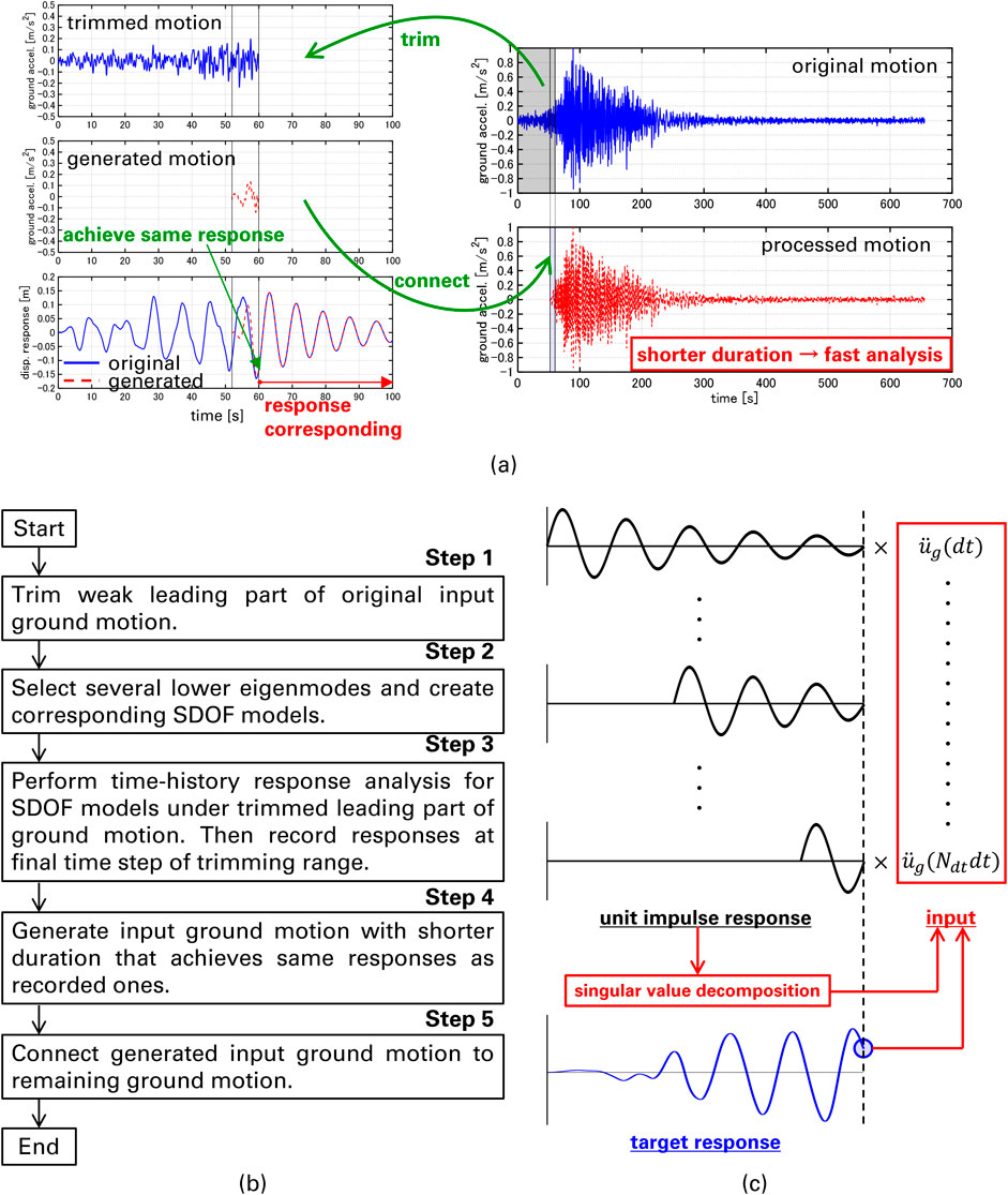
Figure 1. Overview of proposed method, (a) schematic diagram, (b) procedure, (c) input signal generation.
The proposed generation method is based on the singular value decomposition and unit impulse responses in a discrete time system. The matrix consisting of the unit impulse response at each time step is decomposed and the substitute ground motion with shorter duration is generated. The details of the generation method are explained in Section 3. The response under the original ground motion and that under the finally obtained ground motion almost correspond after the end time of the trimming range. This is because linear elastic models are treated, and the superposition principle holds for the responses under the trimmed and remaining parts of ground motion. When the maximum responses occur after the trimming end time, the maximum responses can be evaluated accurately and efficiently. Furthermore, when the trimming range is short enough, the responses of elastic-plastic models under those ground motions almost correspond since the models will remain elastic under the leading part of the ground motion. The trimming range is rationally determined through ground acceleration and velocity power, which measure intensity of a ground motion (Takewaki, 2004; Akehashi and Fujita, 2025). Note that the selection of SDOF models should be changed depending on the targeted structural model. How many eigenmodes should be chosen for generating ground motion can be determined based on the effective modal mass.
It should be noted that the proposed method can be applied to the characterization and simplification of pulse-like ground motions (Baker, 2007; He and Agrawal, 2008; Zhai et al., 2013; Yang and Zhou, 2015; Li et al., 2017), the generation of finite impulse ground motions (Kojima and Takewaki, 2015), the active response control (Symans and Constantinou, 1999; Spencer and Nagarajaiah, 2003; Symans et al., 2008), and the down-sampling of input signals (Rabiner and Gold, 1975). The applicability to these uses is explained in the Appendix section.
3 Pseudo-input signal generation method
In this section, the input signal generation methods for single-point input ground motions and multiple-point input ground motions are derived. In addition, the relation between the phase angle of the target response, the duration and amplitude of the generated input ground motion is discussed.
3.1 Single-point input ground motion
Consider
where
where
It should be pointed out that
where
Note that the acceleration responses
It is also noted that the proposed method works as a response-based filter, and the response and the obtained signals satisfy the equation of motion for every time step. In relation to this, the application to down-sampling of input signals is explained in Supplementary Appendix SC.
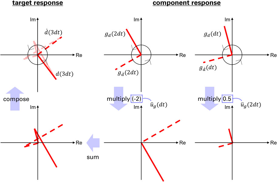
Let us consider a simple example for obtaining
Next, the relation between the phase angle of the target response, the duration and amplitude of the generated input ground motion is investigated.
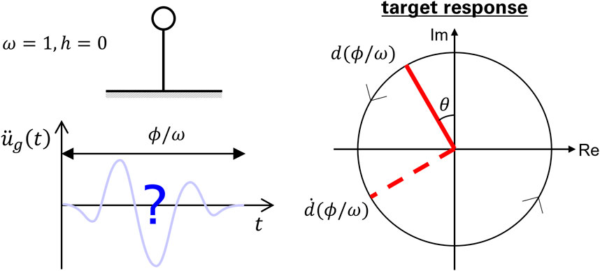
Consider an SDOF building model with mass
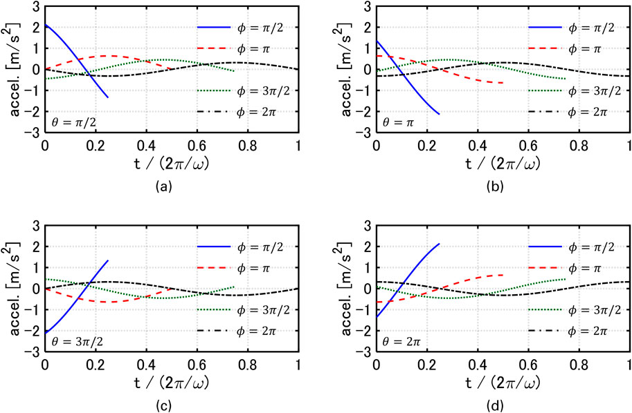
Figures 4, 5 show the relationship between

Figure 4. Relationship between
Note that the setting
3.2 Multiple-point input ground motion
The formulations presented in Section 3.1 are extended to multiple-point input ground motions. Specifically, the input ground motion is expressed in terms of the ground velocity and displacement rather than the ground acceleration.
The equation of motion for an SDOF model with natural circular frequency
where
where
When dealing with multiple-point input ground motions, the above procedure is repeated for each input point. Moreover, the proposed method can be extended to lateral wind loads in a similar manner.
4 Numerical examples
In this section, the effectiveness of the proposed method is investigated through numerical examples for single and multiple-point input ground motions. In addition, the applicability to a full-scale elastic-plastic high-rise building model is also investigated.
4.1 Single-point input ground motion
An artificial ground motion OS1 is treated. OS1 is often used in Japan as a representative of long-duration, long-period ground motions. The duration is about 650 s, and the trimming range is set to
Figures 6a,b show the displacement responses of the four SDOF models under the original and generated motions. Figure 6c shows the generated ground motion. It can be observed that the displacement responses under the generated motions closely match those under the original motion in the range of
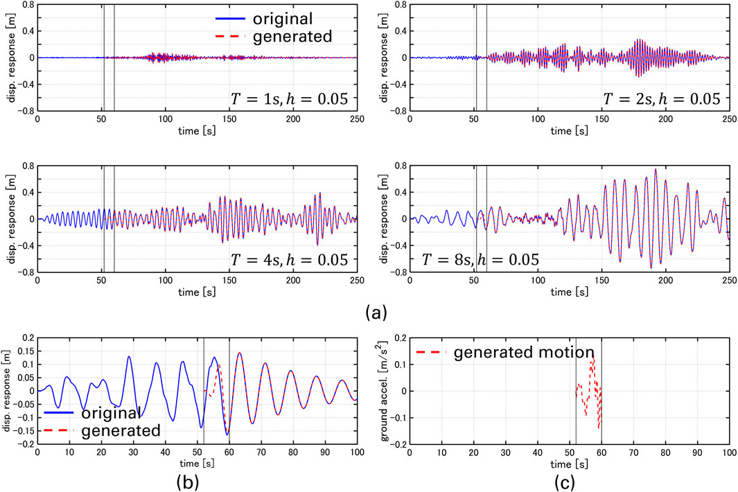
Figure 6. Time-history displacement responses under original and generated motions, (a) displacement responses, (b) enlarged view of displacement responses for SDOF with
4.2 Multiple-point input ground motion
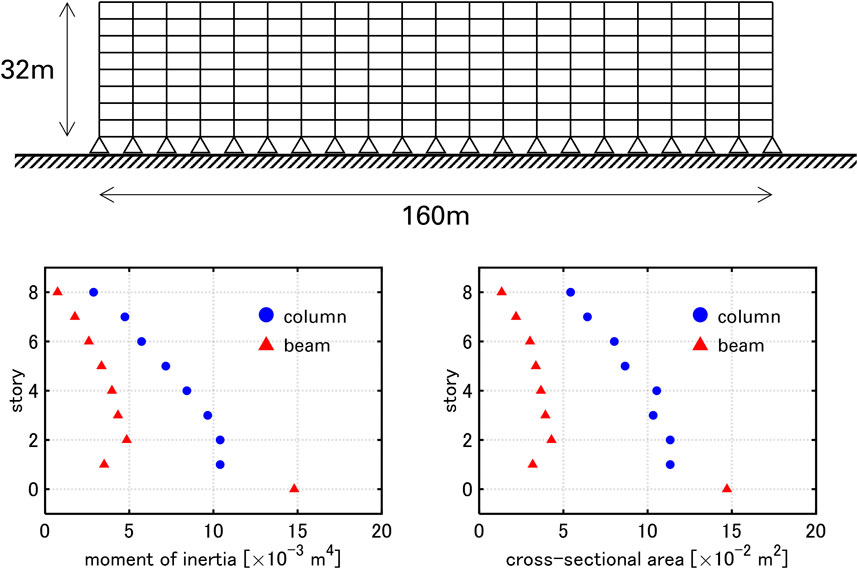
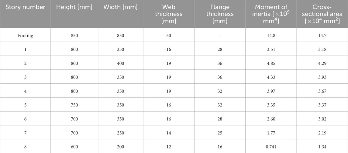
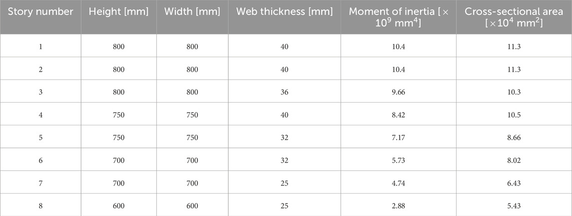
An 8-story, 20-bay planar steel moment frame is treated (Figure 7). The common story height is 4 m, and the common span length is 8 m. The total mass of each floor is 1280 t. A mass of 32 t is allocated to the top nodes of the corner columns, and a mass of 64 t is allocated to the top nodes of the interior columns. The cross-sections dimensions, moment of inertia and cross-sectional area of the frame are listed in Tables 1, 2. H-shape sections are applied to beam sections except for the footing beams, and square box sections are applied to column sections and the footing beams. The cross-sections of columns and beams are common within each story. The moment of inertia and cross-sectional area of the columns and beams are also shown in Figure 7. Young’s modulus is set to

Table 3. Dynamic parameters of 8-story, 20-bay planar steel moment frame under assumption where horizontal displacements of nodes in same floor are identical.
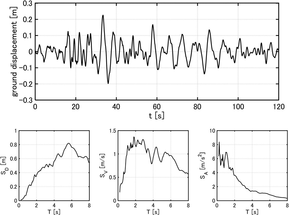
The input ground motion is explained. The ground motion is specified at the engineering bedrock with S-wave velocity
The duration of the ground motion at each input point is 120 s, and the time-history response analysis is performed in the range of
When the horizontal displacements of nodes in the same floor are assumed to be identical, the 1-6 th natural circular frequencies and damping ratios are
Figure 9 shows the generated ground displacement, the 5th floor and top acceleration responses of the moment frame under the original and generated motions. The reference nodes are also illustrated. It can be observed that the displacement responses under the generated motions closely match those under the original motion in the range of
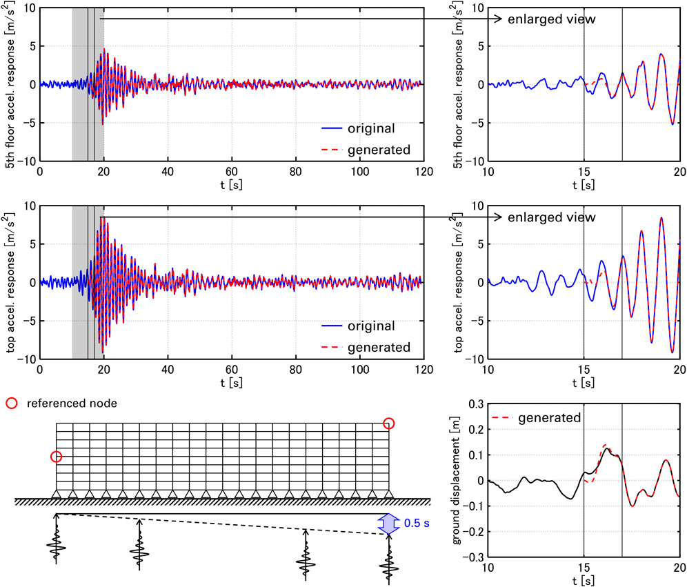
Figure 9. Top and 5th floor acceleration responses under original and generated ground motions and generated ground displacement.
4.3 Full-scale elastic-plastic high-rise building
A full-scale 35-story elastic-plastic building model with a strong back core frame is treated to compare the proposed method with the previous paper (Akehashi and Fujita, 2025). The building model and the ground motion OS1 treated in the previous paper are also used in this paper. The main frame is a reinforced-concrete moment-resisting frame and the subframe is a reinforced-concrete shear-wall structure (Figure 10a). The details of the model are explained in the previous papers (Kawai et al., 2021; Akehashi and Fujita, 2025). PGA of OS1 is set to 2 m/s2. The ranges where the ground acceleration power is below 1% or exceeds 96% of the total are trimmed. Although the previous paper adds single impulse input as a correction process after trimming of the leading part of the ground motion, a generated ground motion whose duration is equal to the fundamental natural period is connected in this paper. The natural eigenmodes are selected in descending order of the effective modal mass until the cumulative mass is larger than 90% of the total mass of the frame. Table 4 shows the natural circular frequencies, the damping ratios and the effective modal mass ratios for x-directional ground motion.
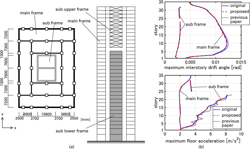
Figure 10. Overview of building model and maximum interstory drift angle and maximum floor accelerations under OS1, (a) plan and section, (b) maximum interstory drift angle and maximum floor accelerations.

Table 4. Dynamic parameters of full-scale 35-story building model (in descending order of the effective modal mass).
Figure 10b presents the maximum interstory drift angle and the maximum floor accelerations. It can be observed that the maximum interstory drift angle and the maximum floor accelerations evaluated by the proposed method show better correspondence with the results for the original motion compared to those evaluated by the previous method. It should be pointed out that the generated ground motion accurately evaluates the higher-mode responses, although the impulse input at the initial time step strongly excites the higher-mode response. Note that it took 75484 s for the analysis under the original motion, and it took 23623, 24084 s for the evaluation by the previous and proposed method.
5 Conclusion
In this paper, a pseudo-input signal generation method that realizes the pre-specified structural responses was proposed. The main conclusions can be summarized as follows.
(1) The proposed input signal generation method is based on the singular value decomposition and unit impulse responses in a discrete time system. The proposed method is applicable not only to a single-point input ground motion but also to multiple-point input ground motions.
(2) One of the most effective uses of the proposed method is the replacement of the leading part of the original input ground motion by the generated input ground motion with the smaller time steps. This leads to an efficient and accurate analysis of the structural responses under not only to a single-point input ground motion but also to multiple-point input ground motions.
(3) The amplitude of the generated signal depends on both the duration of the generated signal and the phase angle of the target response. The amplitude decreases almost monotonically as the duration becomes longer. Additionally, the amplitude varies almost periodically with respect to the phase angle of the target response. However, the phase angle hardly influences the amplitudes when the duration is sufficiently long.
(4) It was demonstrated through the numerical examples for SDOF models, a planar moment-resisting frame, and a full-sacle elastic-plastic high-rise building model under multiple input ground motions that the proposed method accurately and efficiently evaluates the structural responses.
Data availability statement
The raw data supporting the conclusions of this article will be made available by the authors, without undue reservation.
Author contributions
HA: Conceptualization, Writing – original draft, Supervision, Methodology, Visualization, Writing – review and editing, Validation. BW: Methodology, Supervision, Writing – original draft, Writing – review and editing.
Funding
The author(s) declare that no financial support was received for the research and/or publication of this article.
Conflict of interest
Authors HA and BW were employed by Takenaka Corporation.
Generative AI statement
The author(s) declare that no Generative AI was used in the creation of this manuscript.
Publisher’s note
All claims expressed in this article are solely those of the authors and do not necessarily represent those of their affiliated organizations, or those of the publisher, the editors and the reviewers. Any product that may be evaluated in this article, or claim that may be made by its manufacturer, is not guaranteed or endorsed by the publisher.
Supplementary material
The Supplementary Material for this article can be found online at: https://www.frontiersin.org/articles/10.3389/fbuil.2025.1598751/full#supplementary-material
References
Akehashi, H., and Fujita, N. (2025). A new processing method of ground acceleration data for fast and accurate evaluation of maximum seismic structural response. Jpn. Archit. Rev. 8 (1), e70008. doi:10.1002/2475-8876.70008
Akehashi, H., and Takewaki, I. (2022a). Inverse optimal damper placement via shear model for elastic–plastic moment-resisting frames under large-amplitude ground motions. Eng. Struct. 250, 113457. doi:10.1016/j.engstruct.2021.113457
Akehashi, H., and Takewaki, I. (2022b). Bounding of earthquake response via critical double impulse for efficient optimal design of viscous dampers for elastic-plastic moment frames. Jpn. Archit. Rev. 5 (2), 131–149. doi:10.1002/2475-8876.12262
Akehashi, H., Watai, K., and Kamoshita, N. (2025). Inverse eigenmode modeling and multi-scale seismic analysis of irregular frame structure by shear spring-multi floor mass system. Struct. Des. Tall. Spec. Build. 34 (2), e2215. doi:10.1002/tal.2215
Baker, J. W. (2007). Quantitative classification of near-fault ground motions using wavelet analysis. Bullet. Seism. Soc. Am. 97 (5), 1486–1501. doi:10.1785/0120060255
Chang, P. C., Flatau, A., and Liu, S. C. (2003). Review paper: health monitoring of civil infrastructure. Struct. Health Monit. 2 (3), 257–267. doi:10.1177/1475921703036169
Chioccarelli, E., and Iervolino, I. (2010). Near-source seismic demand and pulse-like records: a discussion for L’Aquila earthquake. Earthq. Eng. Struct. Dyn. 39 (9), 1039–1062. doi:10.1002/eqe.987
Enokida, R., Takewaki, I., and Stoten, D. (2014). A nonlinear signal-based control method and its applications to input identification for nonlinear SIMO problems. J. Sound. Vibr. 333 (24), 6607–6622. doi:10.1016/j.jsv.2014.07.014
Farrar, C. R., and Worden, K. (2007). An introduction to structural health monitoring. Philosophical Trans. R. Soc. A Math. Phys. Eng. Sci. 365 (1851), 303–315. doi:10.1098/rsta.2006.1928
Gladwell, G. M. (1986). Inverse problems in vibration. Appl. Mech. Rev. 39, 1013–1018. doi:10.1115/1.3149517
He, W. L., and Agrawal, A. K. (2008). Analytical model of ground motion pulses for the design and assessment of seismic protective systems. J. Struct. Eng. 134 (7), 1177–1188. doi:10.1061/(asce)0733-9445(2008)134:7(1177)
He, Y., Li, S., Wei, Y., and Xie, L. (2023). A novel strong ground motion duration to reduce computation time of structural time history analysis. Soil Dyn. Earthq. Eng. 164, 107641. doi:10.1016/j.soildyn.2022.107641
Kawai, A., Maeda, T., and Takewaki, I. (2021). Critical response of high-rise buildings with deformation-concentration seismic control system under double and multi impulses representing pulse-type and long-duration ground motions. Front. Built Environ. 7, 649224. doi:10.3389/fbuil.2021.649224
Kojima, K., and Takewaki, I. (2015). Critical earthquake response of elastic–plastic structures under near-fault ground motions (Part 1: fling-step input). Front. Built Environ. 1, 12. doi:10.3389/fbuil.2015.00012
Koyamada, K., Miyamoto, Y., and Miura, K. (2005). “Nonlinear property for surface strata from natural soil samples,” in Proc. Japan national conf. Geotech. Eng., volume JGS38, session ID 1039, 2077–2078.
Li, S., Zhang, F., Wang, J. Q., Alam, M. S., and Zhang, J. (2017). Effects of near-fault motions and artificial pulse-type ground motions on super-span cable-stayed bridge systems. J. Bridge Eng. 22 (3), 04016128. doi:10.1061/(asce)be.1943-5592.0001008
Majidi, N., Riahi, H. T., and Zandi, S. M. (2023). Evaluating the performance of different mother wavelet functions for down-sampling of earthquake records. Structures 51, 846–879. doi:10.1016/j.istruc.2023.03.032
Mazza, F., and Labernarda, R. (2021). “Concave surface base-isolation system against seismic pounding of irregular adjacent buildings,” in 14th world congress in computational mechanics (WCCM), ECCOMAS congress 2020.
Mazza, F., and Labernarda, R. (2022a). Internal pounding between structural parts of seismically isolated buildings. J. Earthq. Eng. 26 (10), 5175–5203. doi:10.1080/13632469.2020.1866122
Mazza, F., and Labernarda, R. (2022b). Effects of near-fault acceleration and non-acceleration pulses on pounding between in-plan irregular fixed-base and base-isolated buildings. Struct. Contr. Health Monit. 29 (9), e2992. doi:10.1002/stc.2992
Pant, D. R., and Wijeyewickrema, A. C. (2013). Influence of near-fault ground motions on the response of base-isolated reinforced concrete buildings considering seismic pounding. Adv. Struct. Eng. 16 (12), 1973–1988. doi:10.1260/1369-4332.16.12.1973
Porter, B. (1970). Synthesis of linear lumped-parameter vibrating systems by an inverse Holzer technique. J. Mech. Eng. Sci. 12 (1), 17–19. doi:10.1243/jmes_jour_1970_012_005_02
Rabiner, L. R., and Gold, B. (1975). Theory and application of digital signal processing. Englewood Cliffs: Prentice-Hall.
Reyes, J. C., Avila, W. A., Kalkan, E., and Sierra, A. (2021). Reducing processing time of nonlinear analysis of symmetric-plan buildings. J. Struct. Eng. 147 (6), 04021073. doi:10.1061/(asce)st.1943-541x.0003000
Reynders, E. (2012). System identification methods for (operational) modal analysis: review and comparison. Arch. Comput. Meth. Eng. 19, 51–124. doi:10.1007/s11831-012-9069-x
Schnabel, P. B., Lysmer, J., and Seed, H. B. (1972). “SHAKE: a computer program for earthquake response analysis of horizontally layered sites,” in A computer program distributed by NISEE/Computer Applications. Berkeley.
Sohn, H., Farrar, C. R., Hemez, F. M., Shunk, D. D., Stinemates, D. W., Nadler, B. R., et al. (2003). A review of structural health monitoring literature: 1996–2001, 1. USA: Los Alamos National Laboratory, 16.
Spencer, Jr. B. F., and Nagarajaiah, S. (2003). State of the art of structural control. J. Struct. Eng. 129 (7), 845–856. doi:10.1061/(asce)0733-9445(2003)129:7(845)
Suzuki, T. (2019). Input motion inversion in elastoplastic soil model using modal iterative error correction method. Jpn. Archit. Rev. 2, 340–348. doi:10.1002/2475-8876.12092
Symans, M. D., Charney, F. A., Whittaker, A. S., Constantinou, M. C., Kircher, C. A., Johnson, M. W., et al. (2008). Energy dissipation systems for seismic applications: current practice and recent developments. J. Struct. Eng. 134 (1), 3–21. doi:10.1061/(asce)0733-9445(2008)134:1(3)
Symans, M. D., and Constantinou, M. C. (1999). Semi-active control systems for seismic protection of structures: a state-of-the-art review. Eng. Struct. 21 (6), 469–487. doi:10.1016/s0141-0296(97)00225-3
Takewaki, I. (2004). Bound of earthquake input energy. J. Struct. Eng. 130 (9), 1289–1297. doi:10.1061/(asce)0733-9445(2004)130:9(1289)
Verhaegen, M. (1994). Identification of the deterministic part of MIMO state space models given in innovations form from input-output data. Automatica 30 (1), 61–74. doi:10.1016/0005-1098(94)90229-1
Yang, D., and Zhou, J. (2015). A stochastic model and synthesis for near-fault impulsive ground motions. Earthq. Eng. Struct. Dyn. 44 (2), 243–264. doi:10.1002/eqe.2468
Keywords: unit impulse response, singular value decomposition, inverse problem, computational efficiency, multiple-point input ground motion, earthquake response analysis
Citation: Akehashi H and Wang B (2025) Pseudo-input signal generation for smart structural control and fast seismic response analysis. Front. Built Environ. 11:1598751. doi: 10.3389/fbuil.2025.1598751
Received: 23 March 2025; Accepted: 15 April 2025;
Published: 28 April 2025.
Edited by:
Jia Guo, Kyoto University, JapanReviewed by:
Rodolfo Labernarda, University of Calabria, ItalyYıldırım Serhat Erdoğan, Yıldız Technical University, Türkiye
Copyright © 2025 Akehashi and Wang. This is an open-access article distributed under the terms of the Creative Commons Attribution License (CC BY). The use, distribution or reproduction in other forums is permitted, provided the original author(s) and the copyright owner(s) are credited and that the original publication in this journal is cited, in accordance with accepted academic practice. No use, distribution or reproduction is permitted which does not comply with these terms.
*Correspondence: Hiroki Akehashi, YWtlaGFzaGkuaGlyb2tpQHRha2VuYWthLmNvLmpw
 Hiroki Akehashi
 Bohan Wang