 Wei Wang
 Mingrong Duan
 Zhenwei Zeng1,2
- 1School of Electrical and Automation Engineering, Nanjing Normal University, Nanjing, China
- 2Key Laboratory for Integrated Energy With Electricity-Gas Interconnection of Jiangsu Province, Nanjing, China
This paper presents the optimized structure of the multi-relay coils insulator of WPT system. With the rapid development of the smart grid, on-line monitoring devices in the transmission tower have been widely used. However, the power supply problem has become an important bottleneck in the development of transmission tower intelligent sensing technology. Hence, the multi-relay coils wireless power transfer technology has been proposed to supply for the tower monitoring equipment in this paper. Compared with traditional multi-relay coils, the effects of the number, arrangement position and turns of relay coils on the performance of WPT system are further explored. The simulation results show that the operation performance of WPT can be significantly improved by optimizing the coil arrangement position and turns. Moreover, there are multiple configuration schemes that the design indexes of the system could be achieved. The experiment results show that in the 110 kV high-voltage transmission with the insulator length of 1.015 m, the transmitting power and efficiency of the WPT system could be increased to 1.81 W and 60.11% respectively by parameters optimization, which ensures the continuous and stable work of the monitoring equipment.
1 Introduction
With the development of smart grid, in order to improve the safe and stable operation level of power grid, a great quantity of online monitoring equipment, such as temperature monitoring, image and video monitoring, are deployed on high-voltage line towers. To realize the reliable transmission of various status information of transmission towers, so as to further improve the popularization and application of power grid digital technology. Due to the harsh installation environment and green issues, the monitoring equipment on the tower needs an independent and stable power supply for the maintenance-free. However, the power requirements of various monitoring equipment are different. Therefore, with the continuous improvement of online monitoring requirements for transmission towers, it is meaningful to explore the reliable power supply method of monitoring equipment to ensure its long-term reliable operation in the field.
At present, the power supply solutions for online monitoring equipment mainly include: 1) traditional energy storage equipment such as chemistry batteries and UPS; 2) renewable energy such as wind energy and solar energy; 3) laser and optical fiber, etc., but these methods are not practical and economical (Zhou et al., 2022; Zhao et al., 2015); (Zhao et al., 2013). In recent years, the combination of energy harvester and Wireless Power Transfer (WPT) technology has provided a new power supply solution for power transmission tower monitoring equipment, which has attracted more and more attention from researchers (Huang et al., 2019; Jiang et al., 2021; Hou et al., 2021; Wang et al., 2021). The WPT technology can extract electromagnetic energy from power line by energy harvester, and transmit it to the low-voltage side of the tower over a long distance to supply power to the monitoring equipment. This method is not affected by the external environment, and it is a reliable and stable power supply method for online monitoring equipment. Meanwhile, the research on wireless power supply of transmission towers mainly focuses on improving the power taken by magnetic field energy harvester (Wang et al., 2019; Yan et al., 2022; Zeng et al., 2021), while there are relatively few researches on the long-distance, efficient and stable transmission of energy from transmission lines to monitoring equipment.
Cai et al. (2018) designed a new WPT system based on magnetic resonance coupling for 110 kV transmission tower monitoring equipment charging. The energy efficiency of the system does not exceed 33%. Liu and Tan (2018) proposed to embed a single relay coil inside the insulating pillar to realize wireless power supply of online monitoring equipment, and studied the optimal installation position of the relay coil, but there is no mention of the influence of the introduction of the relay coil on the insulation performance of the insulation strut. Zhang et al. (2017) proposed a 12-coils insulator domino relay WPT system. The power supply distance of the system is 1.1 m, and the transmission efficiency is about 60%. However, the internal resistance loss of the coil is large, and the system transmission efficiency is low. Zhou et al. (2019) proposed to wind multiple relay coils in a composite insulator shed, and the influence of the number of coils and operating frequency on the transmission efficiency of the system was further analyzed. However, the influence of the key parameters of the coil, such as the arrangement position of the coil and the number of coil turns, on the transmission performance of the system is not analyzed. However (Wang et al., 2018; Sun et al., 2011), the number of coils, the arrangement position and the number of turns directly affect the coupling coefficient between the coils, which in turn affects the transmission performance of the system.
In this paper, a novel wireless power transmission tower system based on insulator structure is studied, and the relationship between the energy transmission power and efficiency of the multi-relay coil WPT system and the number of coils, arrangement position and number of turns is analyzed. Under the circumstances of above-mentioned transmission tower WPT system, through the design of the coil arrangement position and the number of turns, it is analyzed whether there is an optimal coil arrangement and the optimal number of coil turns, so that the system can achieve the maximum energy transmission efficiency while satisfying the load power. It provides a reference for the parameter design of the actual transmission tower WPT system.
2 Transmission tower online monitoring equipment WPT systems
Figure 1 illustrates the structure of WPT system of the transmission tower online monitoring equipment. The system is mainly composed of energy harvester, power converter, multi-relay coil and rectifier voltage regulator module. At present, the research on energy harvester and energy converter is relatively mature. Hence, this paper focuses on the part of multi-relay wireless power transmission unit.
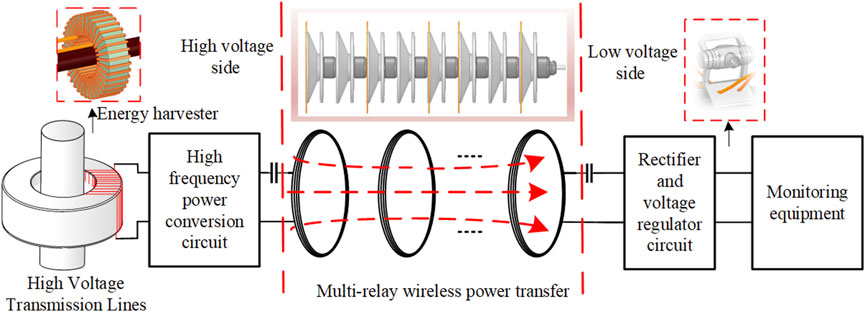
FIGURE 1. WPT system of transmission tower on-line monitoring equipment.
In this paper, a new energy transmission tower WPT system based on insulators is proposed. The insulator is composed of connecting hardware, umbrella skirt, etc. The umbrella skirt is made of integral injection molding process, which is suitable for embedding the relay coil. The new insulator structure can use ceramic insulators, glass insulators, etc., as the carrier. In order to facilitate the system analysis, this paper adopts the standard XWP2-70C suspension insulator, considering the voltage level insulation requirements of 110 kV transmission towers, and 8 standard insulators are connected in series. The size and structure are depicted in Figure 2. Considering the unity of the resonant coil, this paper embeds the resonant coil in a large-diameter insulating disk, which is easy to process and install. On the diameter insulating disk, several relay coils are embedded on the large-diameter insulating disk in the middle part. ②, ③, …, ⑦ marked in Figure 2 are the positions where the relay coils can be embedded.
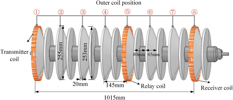
FIGURE 2. 110 kV composite insulator embedded coil location diagram.
3 Theoretical principle analysis of WPT system
The equivalent circuit model of the multi-relay coil WPT system is shown in Figure 3. Here, Us refers to the equivalent high frequency mains RMS for energy harvester and power converters. RL denotes the equivalent load of receiver rectifier and monitoring equipment. Where Ls, Cs, Rs represent the self-inductance, compensation capacitance and equivalent internal resistance of the transmitting coil. Where Lr, Cr, Rr represent the self-inductance, compensation capacitance and equivalent internal resistance of the receiving coil,Li, Ci, Ri(i∈1,2, … ,n) refers to the self-inductance, compensation capacitance and equivalent internal resistance of relay coil I,
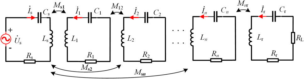
FIGURE 3. Equivalent circuit of multi-relay coil WPT system.
ω refers to the operating angular frequency of the system, and the resonant frequency of each coil loop should be consistent, which can be defined as
The size of the transmitter coil, the relay coil and the receiver coil are the same. To simplify the analysis, the internal resistance and self-inductance of each coil can be regarded as equal. That is, Ls = Li = Lr = L, Cs = Ci = Cr = C, Rs = Ri = Rr = R(1 ≤ i ≤ n), according to Kirchhoff’s law and mutual inductance coupling theory, the loop equations of each coil of the system are listed, which can be expressed as follows
The transmission efficiency η and transmission power PL of the multi-relay coil WPT system can be expressed as
Is, I1, I2, Ii (i = 1,2, … ,n), Ir denotes the effective value of current flowing through each coil. Ignoring the influence of mutual inductance between non-adjacent coils on system performance, the current ratios Is/Ir and In/Ir can be obtained as
Relevant studies have shown that when the transmission distance exceeds 1 m, if the coil size and system frequency are limited, the transmission power and efficiency of a single-relay coil or dual-relay coil WPT system may not be able to meet the power supply requirements of online monitoring equipment at the same time. Furthermore, as shown in Figure 2, on the 110 kV insulator string, the maximum number of relay coils that can be embedded is 6. Hence, this paper studies the parameters of the WPT system with three-relay, four-relay, five-relay and six-relay coils. First, the current ratios of the three-relay coil WPT system are obtained by solving
Eq. 6 shows that the expressions of each current ratio are complicated, so we need to simplify it. In this paper, the system parameters are designed:
In the same way, the current ratios of other multi-relay coil WPT systems can be obtained, and then substituting into Eq. 3, the transmission efficiency expressions of three-relay, four-relay, five-relay and six-relay coil WPT systems can be obtained as shown in Eq. 8, the system transmission power can be obtained from Eq. 4
When the coil size is the same, the mutual inductance between two coaxial circular helical coils can be expressed by Eq. 9
The equivalent internal resistance of the coil can be approximated by the following equation.
Where, N, r represent the number of coil turns and the coil radius, θ and ϕ represent the integral molecules, dij denotes the spacing between coil i and coil j, μ0, a, σ denote the vacuum coefficient, the diameter of the hollow wire and the electrical conductivity. Where, μ0 = 4π×10−7 H/m, and the electrical conductivity of copper is σ = 5.8 S/m × 107 S/m. According to the above equation, it can be seen that the transmission power and transmission efficiency of the system are directly affected by the mutual inductance between the coils and the internal resistance of the coils. The mutual inductance between each coil is affected by the number of coil turns N and the distance between each coil dij, and the number of coil turns N also affects the internal resistance of the coil, which in turn directly affects the transmission power and efficiency of the system.
In this paper, the multi-relay coil WPT system based on the insulator string shown in Figure 2 is studied (By introducing multi-relay coils in the insulator string, the optimal coil arrangement position and the number of coil turns of the system are analyzed, so as to meet the power requirements of the monitoring equipment, while the transmission efficiency is maximum). When multi-relay coils are introduced into the insulator string, the optimal coil arrangement position and the number of coil turns under the maximum transmission efficiency of the system are analyzed, and the system power meets the requirements of monitoring equipment. In this paper, 0.1*80 mm Litz wire is used. Taking the firmness of the embedded coil and the thickness of the insulator disk into consideration, the number of turns of the coil should not exceed 16. Meanwhile, considering the firmness of the externally embedded coil, the diameter of the externally embedded coil is slightly larger than the diameter of the insulating disc, which is 258 mm. At the same time, due to the limitation of the actual length of the insulator string, there are certain restrictions on the number and arrangement of the embedded coils, which cannot be placed at will. This point needs to be considered when arranging the coil positions. The system parameters have the following constraints
Where, dsr denotes the total transmission distance, PL0 represents the minimum transmission power required by the online monitoring equipment, and η0 represents the minimum transmission efficiency that the system meets. The monitoring equipment on the transmission tower mainly includes temperature monitoring, tower tilt monitoring, etc. The power supply of monitoring sensor is small. Therefore, this paper takes the minimum transmission power PL0 = 1.5 W and the minimum transmission efficiency η0 = 40% as the goal, and seeks the system optimization parameters when the system transmission efficiency is maximum.
Substitute Eqs 9, 10 into Eqs 4, 8. Under the restriction condition as Eq. 11 described, With the help of MTALAB simulation software, the influence of changes of coil turns and arrangement position on transmission power and efficiency of WPT system with each trunk coil is discussed. Table 1 lists the key system parameters.
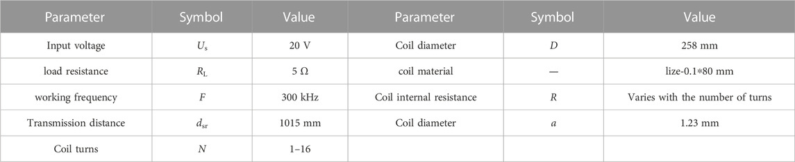
TABLE 1. System parameters.
4 Parameter optimization simulation analysis of WPT system
4.1 Three-relay and four-relay coil WPT system parameter optimization
As shown in Figure 2, considering the actual position of the coil on the insulator string, fix the transmitting coil and the receiving coil on the head and end of the insulating disk, and embed 3 relay coils on the 6 insulating disks in the middle. There are various arrangements for the nesting of repeater coils. Figure 4 shows the performance of the three-relay coil WPT system changes with the number of coil turns or position, where {①②④⑥⑧} indicates the coil positions are: {ds1 = 145 mm, d12 = 290 mm, d23 = 290 mm, d3r = 290 m}. The distances indicate that the coils are embedded on the first, second, fourth, sixth and eighth insulator disks as shown in Figure 2. As shown in Figure 4, when the coil position is {①②④⑥⑧}, the transmission power of the system increases first and then decreases with the increase of the number of coil turns N, indicating that the larger N is, the better the system performance is. At the same time, the corresponding transmission performance varies greatly when the positions are arranged. As shown in Figure 4, there are various coil arrangements that satisfy the optimization conditions. On this basis, in order to meet the power demand and transmission efficiency, it can be obtained that when the coil arrangement position is {①②④⑥⑧}, when N = 15, the efficiency can reach 59.78% and the power is 1.56 W, which is the optimal system parameter configuration for the three-relay WPT system.
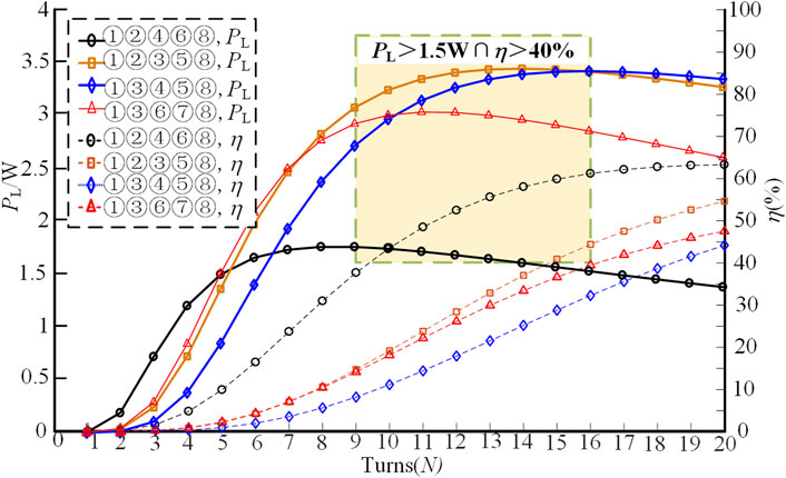
FIGURE 4. The performance of the three-relay coil WPT system varies with N or position.
The following continues to study the system power and efficiency of different arrangements of four-relay coils. In the four-coil WPT system, when the arrangement is {①②③④⑤⑧, ①②④⑤⑦⑧}, the transmission power and efficiency of the system are very low. Therefore, this paper will no longer explain these arrangements, and only analyze in detail the arrangements with better system transmission power and efficiency performance. As shown in Figure 5, the performance of the four-relay coil WPT system varies with the number of turns N under some different coil arrangement positions. When N < 9 or N > 16 the condition of the system optimization objective cannot be satisfied under any arrangement. When arranging the positions {①②③④⑥⑧} and {①②④⑥⑦⑧}, the transmission power and efficiency curves of the two are almost the same. When the arrangement position is {①②③④⑥⑧} and N = 15, PL = 1.52W, η = 59.19%; When the arrangement position is {①②④⑥⑦⑧} and N = 14, PL = 1.84W, η = 58.28%, both schemes satisfy the system optimization objective.
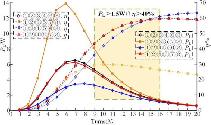
FIGURE 5. The performance of the four-relay coil WPT system varies with N or position.
4.2 Five-relay and six-relay coil WPT system parameter optimization
When the number of relay coils is 5, there are 6 possible arrangements. The parameters of the system when the coils are arranged in different positions are listed in Table 2.
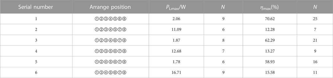
TABLE 2. Parameters of the system when the coils are arranged in different position.
As shown in Table 2, when the arrangement mode is number 1, the optimal power value is PLmax = 2.06 W, and the corresponding number of turns is 9. The optimal value of efficiency is ηmax = 70.62%, and the corresponding number of turns is N = 25. In the arrangement mode 2, 4 and 6, the maximum transmission power can reach more than 10 W, but the maximum transmission efficiency is less than 20%, which is not an ideal arrangement. However, in the arrangement of 1, 3 and 5, the maximum transmission power can reach more than 1.5 W, and the maximum transmission efficiency can also reach more than 55%, but the corresponding turns are not the same value. Therefore, we continue to discuss the optimization scheme of system parameter configuration that simultaneously meets the load power demand and transmission efficiency. As shown in Figure 6, the simulation obtains the variation curve of the performance of the five-relay WPT system with the number of turns under the arrangement 1, 3, and 5. There are various configuration schemes such that both transmission power and efficiency meet the minimum requirements. In summary, when the coil arrangement position of the system is {①②③④⑤⑥⑧} and the number of turns N = 15, the system transmission performance is optimal. At this time, the transmission power is 1.93 W and the transmission efficiency is 61.27%.
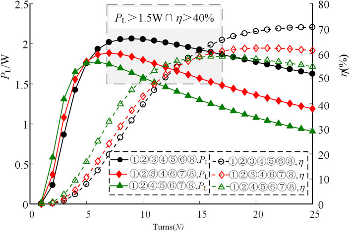
FIGURE 6. The performance of the five-relay coil WPT system varies with N or position.
When the number of relay coils is 6, there is only one arrangement of coil positions. Figure 7 shows the variation of the performance of the six-relay coil WPT system with the number of turns. The domino structure WPT system studied in the literature (Zhang et al., 2017; Zhou et al., 2019) considers that the more the number of relay coils and the number of turns, the higher the transmission efficiency. Figure 7 shows that in the application scenario of the 110 kV insulator string structure in this paper, when the number of relay coils takes the maximum value of n = 6 and the number of turns takes the maximum value of N = 16, the transmission power is 1.64 W and the transmission efficiency is 52.5%. After optimization in this paper, the number of turns is N = 12. At this time, the maximum transmission efficiency of the system is 56.09%, and the corresponding power is 3.86 W, which is better than the coil parameter configuration method in the literature (Zhang et al., 2017; Zhou et al., 2019). At the same time, the experimental result indicates that the transmission power of the system reached more than 10 W when N = 4–8. Therefore, if you want to supply power to the load with power greater than 10 W, the number of turns that can be used is N = 8. As shown in Figure 7, the system transmission power and The efficiency is B1 point and B2 point respectively. At this time, the transmission power is 11.65 W, and the efficiency also reaches 48.41%, which not only meets the power supply demand of the load, but also ensures the energy transmission efficiency.
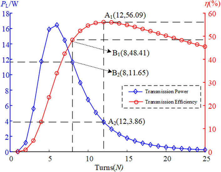
FIGURE 7. The performance of the six-relay coil WPT system varies with N or position.
4.3 Parameter configuration scheme of WPT system for transmission tower online monitoring equipment
In the above, the parameter optimization of the WPT system with different numbers of relay coils is discussed in detail, and the optimal coil parameter configuration scheme is obtained, as shown in Table 3, and the system transmission performance corresponding to each configuration scheme is shown in Figure 8. As shown in Table 3 and Figure 8, by optimizing the coil arrangement position and the number of turns N, using different numbers of relay coils, the transmission power of the system can reach 1.5 W, and the transmission efficiency can reach more than 55%. At the same time, the number of relay coils, the number of turns and the system performance are not simply proportional. When optimizing system parameters, the corresponding parameter optimization scheme can be selected according to the specific needs of the load. If the power supply requirement of the monitoring equipment is about 1 W, and the transmission efficiency is considered to be as large as possible, option 4 can be selected; if the power supply requirement of the monitoring equipment is more than 10W, option 6 can be selected.
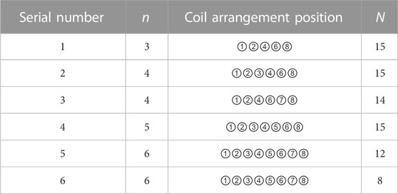
TABLE 3. Optimal parameter configurations under different numbers of relay coils.
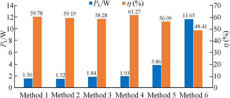
FIGURE 8. System performance under different methods.
5 Test verification
In order to verify the rationality and correctness of the theoretical and simulation analysis, as shown in Figure 9, a test platform was built. The test device includes a DC power supply DH1798-10, a high-frequency inverter (the driving signal is generated by DSP), an oscilloscope Tektronix MSO54, and several cement load (20W/5 Ω). The parameters of the wound resonant coil are shown in Table 1. The error of the measured parameter value of the coil is small, and the average value is taken. The circuit parameters of the system are shown in Table 4.
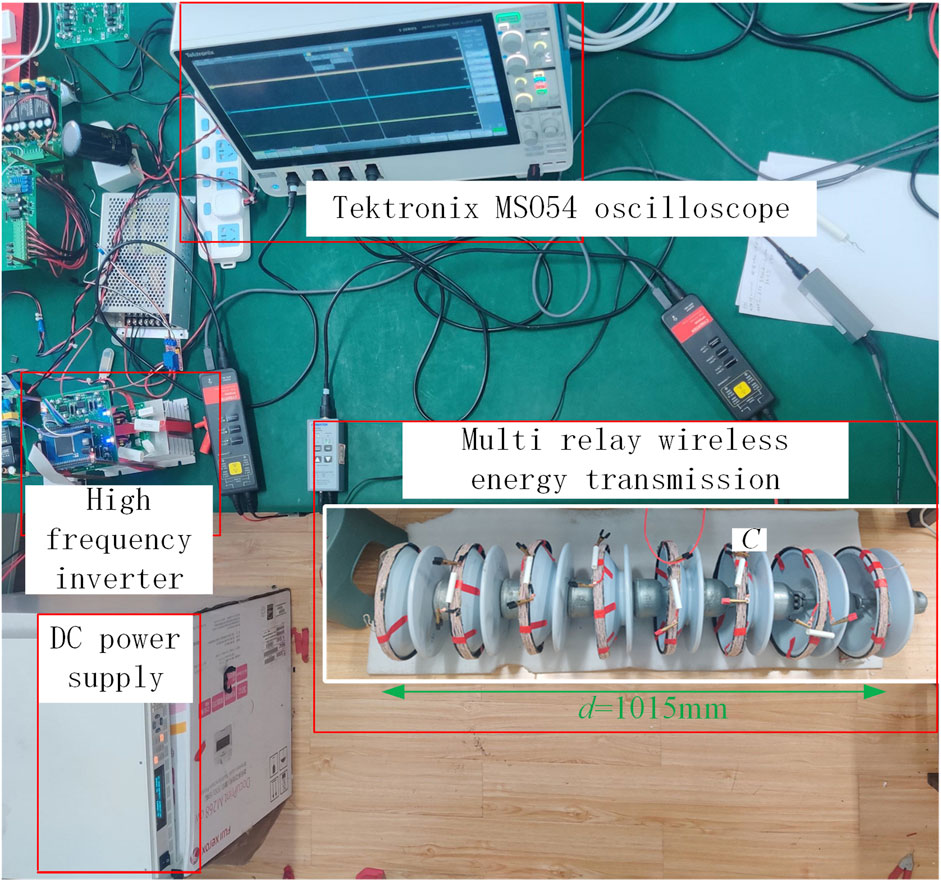
FIGURE 9. WPT experimental platform.
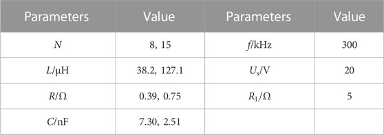
TABLE 4. Actual circuit parameters.
When the system parameter configuration adopts scheme 4, the test waveform is shown in Figure 10, the transmission power is 1.81 W, and the transmission efficiency is 60.11%; when the system parameter configuration adopts scheme 6, the test waveform is shown in Figure 11, and the transmission power is at this time. It is 11.35 W, and the transmission efficiency is 47.19%. By comparing the test results and the simulation data, the transmission performance of the corresponding systems in the test is slightly lower than the simulation results, because the coil internal resistance loss in the test is greater than the theoretical analysis, but the overall results are basically the same, proving the validity of the theory and simulation.
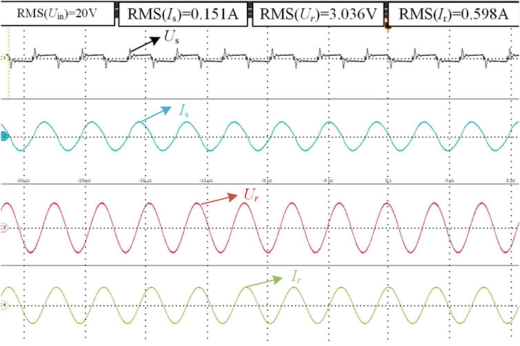
FIGURE 10. Experimental waveform corresponding to Scheme 4
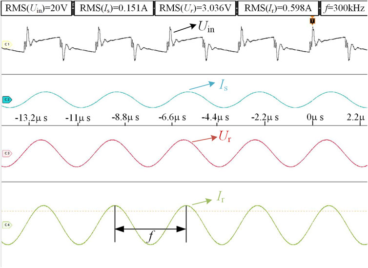
FIGURE 11. Experimental waveforms corresponding to Scheme 6
6 Conclusion
In this paper, the coil is embedded in the insulator string to wirelessly supply power to the online monitoring equipment of the 110 kV transmission tower. By exploring the relationship between the transmission power and efficiency of the system and the number of relay coils, the arrangement position, and the number of turns, it is obtained that the number of relay coils, the number of turns and the system performance are not simply positive correlations when other parameters of the system are fixed. Compared with traditional multi-relay coils, by optimizing the number, position and number of turns of the relay coils, the transmission performance of the system is significantly improved. At the same time, there are a variety of parameter optimization schemes to make the system transmission performance meet the design indicators. Meanwhile, according to the power supply demand of the monitoring equipment, the corresponding parameter optimization scheme is designed. In summary, the above conclusions provide precedent for the optimal design and application of transmission tower WPT system.
Data availability statement
The original contributions presented in the study are included in the article/supplementary material, further inquiries can be directed to the corresponding author.
Author contributions
All authors listed have made a substantial, direct, and intellectual contribution to the work and approved it for publication.
Funding
This project has been supported by the National Natural Science Foundation of China for Youth (51807095) and the Key Research and Development Program of Zhenjiang (ZD2020005).
Acknowledgments
The authors would like to thank the National Natural Science Foundation of China for Youth (51807095) and the Key Research and Development Program of Zhenjiang (ZD2020005) for funding this research. The authors also acknowledge lively discussions that have shaped the work with: Chenjin Xu(NNU), Jingyu Yang(NNU), Hanli Ren(NNU), Wenbo Su(NNU), Kairui Li(NNU), SiyuanSheng(NNU).
Conflict of interest
The authors declare that the research was conducted in the absence of any commercial or financial relationships that could be construed as a potential conflict of interest.
Publisher’s note
All claims expressed in this article are solely those of the authors and do not necessarily represent those of their affiliated organizations, or those of the publisher, the editors and the reviewers. Any product that may be evaluated in this article, or claim that may be made by its manufacturer, is not guaranteed or endorsed by the publisher.
References
Cai, C., Wang, J., Liu, R., Fang, Z., Zhang, P., Long, M., et al. (2018). Resonant wireless charging system design for 110-kV high-voltage transmission line monitoring equipment. IEEE Trans. Ind. Electron. 66 (5), 4118–4129. doi:10.1109/TIE.2018.2808904
Hou, X., Su, Y., Liu, Z., and Deng, Z. (2021). “Wireless power transfer system of on-line monitoring equipment for high voltage transmission line based on double-sided LCC resonant network,” in Proceedings of the 2021 IEEE PELS Workshop on Emerging Technologies: Wireless Power Transfer (Wow 2021), San Diego, CA, USA, 01-04 June 2021, 1–5. doi:10.1109/WOW51332.2021.9462882
Huang, J., Zhou, Y., Ning, Z., and Gharavi, H. (2019). Wireless power transfer and energy harvesting: Current status and future prospects. IEEE Wirel. Commun. 26 (4), 163–169. doi:10.1109/MWC.2019.1800378
Jiang, Y., Yang, Y., Tan, S. C., and Hui, S. Y. R. (2021). Distribution power loss mitigation of parallel-connected distributed energy resources in low-voltage DC microgrids using A Lagrange multiplier-based adaptive droop control. IEEE Trans. Power Electron 36 (8), 9105–9118. doi:10.1109/TPEL.2021.3050506
Liu, S., and Tan, J. (2018). Study on the vibration mechanism of the relay coil in a three-coil WPT system. Prog. Electromagn. Res. M. 70, 117–126. doi:10.2528/pierm18042603
Sun, X., Lui, K., Wong, K., Lee, W., Hou, Y., Huang, Q., et al. (2011). Novel application of magnetoresistive sensors for high-voltage transmission-line monitoring. IEEE Trans. Magn. 47 (10), 2608–2611. doi:10.1109/TMAG.2011.2158085
Wang, W., Xu, C., Zhang, C., and Chen, C. (2019). Start-up and saturation optimization of high-power energy harvester with compound topologies overhead AC transmission line. IEEE Trans. Emerg. Sel. Top. Power Electron. 8 (4), 3609–3617. doi:10.1109/JESTPE.2019.2941970
Wang, W., Xu, C., Zhang, C., and Yang, J. (2021). Optimization of transmitting coils based on uniform magnetic field for unmanned aerial vehicle wireless charging system. IEEE Trans. Magn. 57 (6), 1–5. doi:10.1109/TMAG.2021.3063796
Wang, W., Yang, S., Yang, J., Wang, Q., and Hu, M. (2018). Optimization analysis of wireless charging system for monitoring sensors overhead the HVPLs based on impedance matching. IEEE Trans. Electromagn. Compat. 61 (4), 1207–1216. doi:10.1109/TEMC.2018.2855201
Yan, Z., Xie, H., Li, Y., He, Z., Yang, H., Zhou, W., et al. (2022). A monitoring equipment charging system for HVTL based on domino-resonator WPT with constant current or constant voltage output. IEEE Trans. Power Electron. 37 (3), 3668–3680. doi:10.1109/TPEL.2021.3123506
Zeng, X., Yang, Z., Wu, P., Cao, L., and Luo, Y. (2021). Power source based on electric field energy harvesting for monitoring devices of high-voltage transmission line. IEEE Trans. Ind. Electron. 68 (8), 7083–7092. doi:10.1109/TIE.2020.3003551
Zhang, C., Lin, D., Tang, N., and Hui, S. R. (2017). A novel electric insulation string structure with high-voltage insulation and wireless power transfer capabilities. IEEE Trans. Power Electron. 33 (1), 87–96. doi:10.1109/TPEL.2017.2706221
Zhao, D., Dai, D., and Li, L. (2015). Electric field energy harvesting for on-line condition-monitoring device installed on high-voltage transmission tower. Electron. Lett. 51 (21), 1692–1693. doi:10.1049/EL.2015.1975
Zhao, X., Keutel, T., Baldauf, M., and Kanoun, O. (2013). Energy harvesting for A wireless monitoring system of overhead high voltage power lines. IET Gener. Transm. Distrib. 7 (2), 101–107. doi:10.1049/IET-GTD.2012.0152
Zhou, J., Zhang, P., Han, J., Li, L., and Huang, Y. (2022). Metamaterials and metasurfaces for wireless power transfer and energy harvesting. Inst. Electr. Electron Eng. 110 (1), 31–55. doi:10.1109/JPROC.2021.3127493
Keywords: wireless power transfer, insulator string, relay coil, position arrangement, parameter optimization
Citation: Wang W, Duan M, Zeng Z, Liu H and Ji Z (2023) Research on optimal coil configuration scheme of insulator relay WPT system. Front. Electron. 4:1034082. doi: 10.3389/felec.2023.1034082
Received: 01 September 2022; Accepted: 12 January 2023;
Published: 26 January 2023.
Edited by:
Robert Cox, University of North Carolina at Charlotte, United StatesReviewed by:
Yong Li, Southwest Jiaotong University, ChinaYanjie Guo, Hebei University of Technology, China
Copyright © 2023 Wang, Duan, Zeng, Liu and Ji. This is an open-access article distributed under the terms of the Creative Commons Attribution License (CC BY). The use, distribution or reproduction in other forums is permitted, provided the original author(s) and the copyright owner(s) are credited and that the original publication in this journal is cited, in accordance with accepted academic practice. No use, distribution or reproduction is permitted which does not comply with these terms.
*Correspondence: Wei Wang, NjEyMDdAbmpudS5lZHUuY24=