 Donato Rubinetti
 Kamran Iranshahi1,3
 Daniel Onwude
 Bart Nicolaï
 Thijs Defraeye
- 1Empa, Swiss Federal Laboratories for Materials Science and Technology, Laboratory for Biomimetic Membranes and Textiles, Dübendorf, Switzerland
- 2BIOSYST-MeBioS, KU Leuven, Heverlee, Belgium
- 3Swiss Federal Institute of Technology, ETH-Zurich, Zurich, Switzerland
- 4Belimed AG, Zug, Switzerland
With electrohydrodynamics (EHD), we can propel air in a low-energy fashion. EHD airflow, or ionic wind, arises when a high voltage gradient is applied to a set of electrodes. The air ionizes between electrodes via corona discharge and accelerates in an electric field, exchanging momentum with the surrounding air. While the ionization process is energy-efficient, reaching competitive flow rates remains challenging from a high-voltage engineering perspective. To increase EHD-generated flow rates, this study experimentally investigates a novel concept called EHD air amplification. The concept uses ionic wind as bleed flow to induce a more significant bulk flow by the air-amplifying Coanda effect. Due to the complex interactions between EHD and dielectric structures for air amplification, the conceptual EHD air amplifier device is designed stage-wise, starting with a simple emitter-collector electrode configuration. First, regular EHD flow was studied in a 150 × 150 × 500 mm3 channel. Then, a dielectric material was added to determine its influence on the electric field. The impact of a converging nozzle on the EHD-generated airflow was subsequently studied. Lastly, the converged nozzle airflow was used to create a bleed flow on a plate to facilitate air amplification of the surrounding air. We show the proof-of-concept for an EHD air amplification system. After a voltage threshold of 14 kV, amplified airstreams up to an amplification factor of 3 were measured. Maximum airflow rates of about 15 m3 h−1 were obtained shortly before electric breakdown at 22 kV. Compared to regular EHD, we achieved a higher aerodynamic performance for the same electric energy invested. The flow rate to electric power ratio increased to 66% in EHD air amplification compared to regular EHD. The proposed EHD air amplifier operates at atmospheric pressure. It lays the groundwork for further optimization studies to position EHD air amplification as a low-energy, low-maintenance, motor- and noiseless airflow generation technology.
Highlights
• Experimental proof-of-concept of EHD air amplification.
• Energy efficiency increase of 66% compared to regular EHD.
• EHD air amplification yields up to 3x the airflow rate as regular EHD.
1 Introduction
Airflow generation is everywhere, with applications ranging from large-scale jet propulsion engines to domestic hand-held hairdryers. In the current state of the art, forced airflow is predominantly generated by mechanical devices with spinning blades. However, such devices often constitute extensive systems that consume considerable energy. HVAC systems, for instance, can account for up to 20% of a country’s total energy consumption (Chua et al., 2013). One possibility to reduce energy consumption and increase efficiency is to customize airflow patterns (Ambaw et al., 2014; Lai, 2020; Zeng et al., 2023). Conventional air-moving devices require airflow guides to distribute the airflow toward a target area. Such airflow guides are typically larger than the fan diameter and pose a flow resistance (Ambaw et al., 2014). While incremental optimizations with current technologies could make ventilation more sustainable, more significant advances require deploying new technologies.
Electrohydrodynamics (EHD), also called ionic wind, is a promising technology that can advance energy-efficient airflow generation (Lai, 2020). EHD allows for the creation of compact air blowers (Zeng et al., 2023), enhanced heat transfer characteristics (Wang et al., 2023; Wang et al., 2013) and improved drying of sensitive biological material while increasing the overall energy efficiency (Onwude et al., 2021). Through precise airflow manipulation, EHD enables the creation of decentralized airflow and the enhancement of existing technologies, leading to reduced energy consumption. For instance, EHD can produce a localized airflow in drying applications, eliminating the need for energy-intensive heating elements and significantly reducing greenhouse gas emissions (Iranshahi et al., 2020). While EHD is a promising technology for generating energy-efficient airflow, it has limitations, such as a limited pressure rise (Jewell-Larsen et al., 2011). However, EHD technology is well-suited for applications requiring vibration-free and silent airflow without moving parts. In addition, this technology requires only a few components to generate airflow, making it a cost-effective solution for various applications.
EHD generates airflow by applying a high voltage gradient between a sharply curved electrode (emitter) and a ground electrode (collector). When a high voltage is applied, the emitter induces an ionized region of air around itself, which moves toward the collector. This is the principle of corona discharge. This discharge forms an atmospheric plasma between the electrodes, leading to airflow known as ionic wind (Defraeye and Martynenko, 2018). Although the air ionization process is energy-efficient (Iranshahi et al., 2020), reaching high EHD flow rates can be challenging due to the high-voltage requirements. The flow rate can be increased by increasing the voltage; however, there is a maximum voltage limit due to arc discharge, causing a sudden electrical breakdown. Nevertheless, it is crucial to increase the flow rate to profit from decentralized EHD-based airflow generation.
Many attempts have been made to increase EHD airspeed and flow rate, including (1) modifications to the electric field with non-ionizing electrodes (Colas et al., 2010; Tirumala and Go, 2011), (2) optimization of electrode shapes (Jewell-Larsen et al., 2006), (3) grouping ionic wind devices into arrays (Kanazawa et al., 2021) and (4) multi-stage EHD pump designs (Rickard et al., 2006). These studies aim to increase the velocity of the airspeed in the desired flow direction. However, success depends on the specific setup and electrode arrangement, as the ions follow the electrical field lines between the emitter and collector electrodes. This cloud of ions can distort the electric field, causing inefficiencies in momentum transfer, especially at high voltages of around 30 kV. In addition, dielectric materials near the electrodes can further disturb the electric field. Despite these challenges, research on EHD airflow improvements has mainly focused on the electrostatic side.
Our experimental study tackles the low flow rate problem from the aerodynamic side by exploring a novel concept called EHD air amplifier. The principle combines EHD with the Coanda effect, which is the tendency of a fluid stream to remain attached to a nearby solid wall (Panitz and Wasan, 1972; Dumitrache et al., 2012). We use EHD to generate a bleed airstream that is multiplied by the air-amplifying Coanda mechanism to raise the overall aerodynamic performance. The Coanda effect induces a secondary fluid stream that enables the primary stream to create a much larger bulk flow due to the amplification of the former. Industrial solid-state air amplifiers typically use pressurized air sources, which require energy-intensive air supply equipment. Our approach is novel in combining air amplifiers driven by EHD technology, which provides a low-energy method for generating airflow.
This study aims to experimentally investigate the benefits of combining low-energy, low-pressure EHD flow technology with air amplification technology using a customizable rig. The goal is to create a simple and effective EHD air amplifier design. To achieve this, we first study free-flow EHD in a 150 × 150 × 500 mm3 channel with needles and wires as ionizing electrodes, then introduce dielectrics and nozzles to evaluate discharge stability. Our findings lead to a design capable of EHD air amplification. We assess key performance metrics, such as electric power consumption, the flow rate per power invested, and the amplification factor. These metrics are compared with traditional EHD designs using needles and wires as emitting electrodes and commercially available air amplifiers and conventional fans. The resulting channel design demonstrates the experimental proof-of-concept for EHD air amplification using the Coanda effect for confined flow.
2 Air amplification technology
2.1 Conventional air amplification
Air amplification is an established technology to enhance airflow without moving parts. Various shapes exist, such as circular air amplifiers of air knives. Figure 1 shows the working principle of a typical air amplifier powered by pressurized air. These solid-state devices convert an airstream of pressurized air into a larger bulk flow, i.e., the amplified airflow, by exploiting aerodynamic phenomena, such as air induction via the Coanda effect and air entrainment. These phenomena arise due to the Bernoulli principle, which states that as the velocity of a fluid increases, its pressure decreases. When a primary airstream, such as pressurized air, flows along a surface, it creates a region of low pressure due to the increased air velocity. This low-pressure area induces a secondary airstream that increases the overall flow rate.
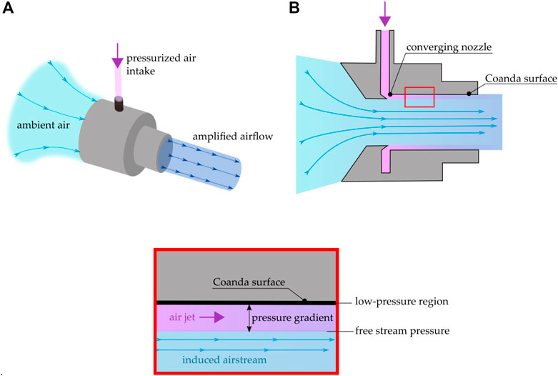
FIGURE 1. Example of an air amplifier fed by pressurized air with (A) showing the working principle and (B) the cross-section view. The detailed view shows the principle of the Coanda effect. As the primary airstream is accelerated through the converging nozzle, it forms an air jet that experiences a pressure gradient. Due to this local pressure effect, it remains attached to the Coanda surface and accelerates an induced airstream leading to an amplified airflow.
Air amplifiers are not typically considered an energy-efficient technology. However, they are popular in industrial or domestic applications because they provide airflow without moving parts, which is desirable for specific tasks like fume extraction or simply for design appeal. Commercially available industrial air amplifiers, such as the Meech (Meech International, 2 Network Point, Range Road, Witney, OX29 0YN, United Kingdom) Air Amplifier (A15xxx series) and High Thrust Jet (A38xxx series), need a supply pressure of 1.4–7 bar for successful operation. They yield an amplification factor of 4–25 depending on the device’s inner diameter (18–100 mm for the Air Amplifier and 9–34 mm for the High Thrust Jet). Dyson (DYSON HOME TECHNOLOGIES PTE. LTD., 2 Science Park Drive, Singapore) offers several products with air amplification technology for domestic applications. These products range from hand-held hair dryers (Dyson Supersonic™, 46.8 m3/h, 1600 W) to domestic ventilators (Dyson Purifier Cool™, 1,044 m3/h, 40 W). In contrast to pressurized air-based amplifiers, the Dyson products are powered by an enclosed impeller.
2.2 Electrohydrodynamic air amplification
Electrohydrodynamic (EHD) air amplification technology is an innovative solution that operates differently than conventional air amplifiers that require pressurized air. EHD air amplification uses corona discharge which ionizes the surrounding air, creating a small EHD-generated airstream. This stream of air is directed towards a Coanda surface. When the EHD-generated airstream, or ionic wind jet, reaches the Coanda surface, it induces a larger airflow due to the Coanda effect by increasing the momentum of the surrounding air. This, in turn, results in a greater airflow rate with no additional energy input. The pressure gradient created by the Coanda effect and air induction creates a self-sustaining amplification effect. EHD air amplification’s energy efficiency comes from using electrohydrodynamic principles. Rather than relying on compressed air, which requires a significant amount of energy, EHD air amplification uses only a small amount of energy to generate corona discharge, the air-driving mechanism.
Figure 2 illustrates the working principle of EHD air amplification, which consists of two interconnected parts. The first part is the fluid flow principle, similar to conventional air amplification, as shown in Figure 2A. This channel geometry contains the necessary elements for air amplification, including a converging nozzle and a Coanda surface. The second principle of operation is the electrostatic principle, as seen in Figure 2B. Instead of using pressurized air, the primary airstream is created locally through corona discharge. The corona discharge is a region of self-sustaining non-thermal plasma between two electrodes. In this example, we use a needle-to-mesh configuration to create EHD airflow. A high voltage is applied to the needle while the mesh is grounded, creating an asymmetric electric field that forms a volume of ionized air around the tip of the needle. This ionized air moves as an ion cloud to the collector electrode, generating macroscopic EHD airflow by exchanging momentum with the surrounding air molecules (Wang et al., 2013). It is important to note that the acceleration region only occurs between the electrodes. The charged molecules experience acceleration via Coulomb force, a product of space charge and electric field. This method of air amplification is highly efficient compared to conventional pressurized air-based amplifiers, as little to no additional energy input is required to achieve competitive flow rates. However, EHD air amplification is a complex phenomenon that is best investigated in a step-wise manner to quantify its benefit. In the next section, we provide details on the experimental study on EHD air amplification.
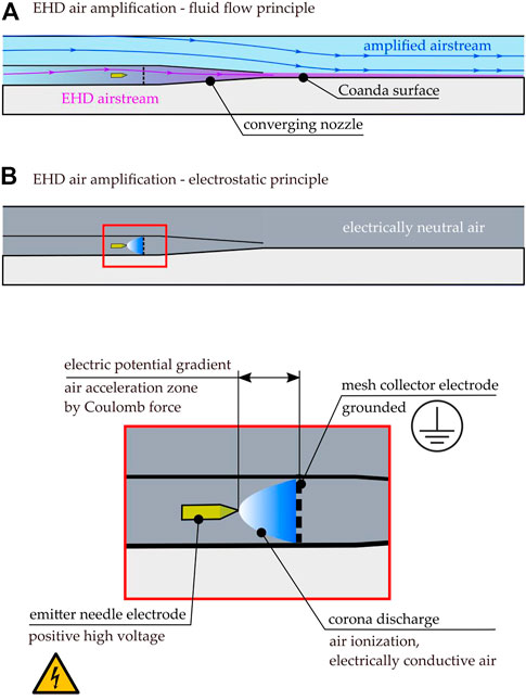
FIGURE 2. The working principle of EHD air amplification consists of (A) the fluid flow part and (B) the electrostatic part. We observe and exploit the same aerodynamic effects in the fluid flow part in regular air amplification. The difference in enhancing energy efficiency comes from the generation of the primary airstream. In EHD air amplification, we use a corona discharge, according to (B), to drive the airflow. Between the emitter and collector electrode, a region of electrically conductive air forms that accelerates and exchanges momentum with the surroundings leading to a macroscopic airflow known as ionic wind. This airstream is directed towards a contracting nozzle and Coanda surface, where it remains attached and amplifies a larger airflow without additional electrical cost.
3 Materials and methods
3.1 Lab setups for EHD air amplification
We constructed several experimental setups. The base setup with peripheral components and measurement devices is described in section 3.1.1. In section 3.1.2, different test rigs are evaluated, which split up the physical phenomena affecting EHD air amplification. We start with an EHD airflow generation device with an emitter electrode and a large mesh collector. The first step is evaluating the size impact of the collector. Second, we evaluate the impact of a dielectric’s presence since the air amplifier’s housing can affect the EHD-generated airflow. Third, we quantify how the airflow contraction, which is present in the air amplifier, affects the EHD-generated flow. Finally, we combine the reduced mesh collector, the dielectric, and the airflow contraction with an external wall, on which the Coanda effect establishes. With this setup, we can quantify the air entrainment of the surrounding air induced by the EHD airflow generation. The idea behind this step-wise approach is that we can analyze and troubleshoot every phenomenon and associated part of the new device.
3.1.1 EHD airflow base setup
Figure 3 shows the base setup of our rig that is customizable to accommodate changes in geometry. The main components are a 150 × 150 × 500 mm3 square cross-section channel made of 5 mm acrylic glass plates. Inside there are the electrical components such as the emitter and collector. The four emitter electrodes have a tip radius of 40 microns and are equally spaced from each other. The emitter electrode has a sufficiently small curvature to ionize air and generate airflow (Bashkir and Martynenko, 2021). The collector consists of soldered 1 mm diameter steel wires with 10 mm spacing between them. This mesh collector lets the accelerated airflow pass, acting like a straight wall for the ions. The electrodes are connected to a high voltage DC power supply (Spellmann SL30PN10) of positive polarity. The hot-wire anemometer (Testo 405i) is placed downstream at the end of the channel to measure a point-wise velocity. For safety reasons, the rig is placed within a customized (1 × 1 × 2 m3) Faraday cage-like environment to meet high voltage precautions.
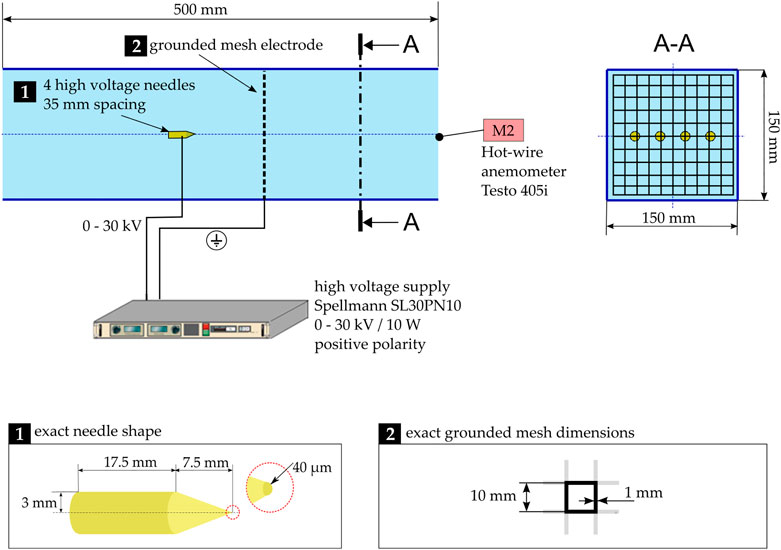
FIGURE 3. Base setup of the test rig with peripheral components. The electrical components (4 emitter needles and a large mesh collector) are accommodated in a 150 × 150 × 500 mm3 channel made of transparent acrylic plates. This base configuration produces EHD airflow without amplification and serves as a starting point for EHD air amplification step-wise exploration. M2 is the point probe measurement location at the outlet for airspeed.
3.1.2 Experimental setup to identify the different phenomena in EHD air amplification
To establish a self-sustaining and continuous Corona discharge that would yield a measurable airstream in a compact area, we investigate the influence of several interconnected factors in EHD air amplification. Step-wise, this was done to approach EHD air amplification conditions as straightforwardly as in Figure 4.
(a) EHD base configuration. This configuration is the basis for EHD operating in free-flow mode. As seen in Figure 4A, the arrangement is the most basic EHD air propulsion technique intended to define the range of operation voltage-wise.
(b) Reduced mesh size and distance to test downsizing possibilities. Here, the large mesh collector is replaced by a same-type mesh strip of 10 × 150 mm2 size, see Figure 4B. The first experimental runs are carried out at an inter-electrode distance of
(c) Introduction of dielectric to assess the stability of the discharge. According to Figure 4C, this step intends to study the influence of an approaching dielectric on the operation range. Introducing a dielectric has implications for the distribution of electric field lines, which may cause instabilities in the self-sustaining discharge. Based on configuration (B), this step introduces two horizontal acrylic glass plates of 5 mm thickness with variable distance in between. The distance is
(d) Introduction of the converging nozzle to concentrate the airflow. In this step, the aerodynamic performance of EHD is checked when a converging nozzle is present, as per Figure 4D. Flow concentration is essential to create a bleed stream of airflow, which amplifies a secondary channel’s airflow rates. The nozzle gap is
(e) Channel extension and introduction of Coanda effect for EHD air amplification. Ultimately, steps (a)-(d) guide the design of an EHD air amplifier, which results in an extended channel, as in Figure 4E. The extension features a flat plate attached to the nozzle where the EHD-generated air jet can flow. The extended channel’s bottom part is closed to establish a clear separation of air domains. EHD air amplification is successful when airspeed is measured at location M3. This means ambient air is accelerated by flow induction from the Coanda effect. The Coanda effect happens when the flow escaping the nozzle remains attached to the solid wall due to pressure asymmetries and thus leads to a greater overall bulk flow. Location M1 measures the EHD-related inflow only, and M2 measures the total outflow. In general, and also in points (a) to (d), M1 and M2 record the airflow at the in- and outlet, respectively. We assume a partially developed channel flow. A more representative measurement could be determining the velocity profile at both M2 and M3. For the proof-of-concept, point measurements are sufficient.
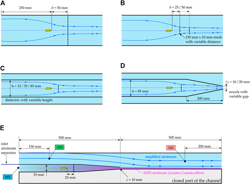
FIGURE 4. Five configurations step-wise approaching EHD air amplification. (A) Is the base configuration, (B) introduces a reduced mesh and closer inter-electrode ga (C) features two acrylic-glass plates with variable distances to study the influence of a nearby dielectric. (D) Includes a converging nozzle to examine the effect of flow contraction. (E) Is the final version of the EHD air amplifier, where the channel extension allows for creating the Coanda effect.
With this step-wise approach, it is possible to clearly distinguish the influence of the various parameters on the complex multiphysical nature of EHD air amplification. Setups (a) to (c) focus on the electrostatic part of the problem while (d) deals with the fluid dynamics. All the runs are repeated with a wire instead of needles for comparison purposes. The performance analysis revealed that a wire emitter is unpractical for an EHD air amplifier, so only the needles are considered emitter for (e), i.e., the final EHD air amplifier proof-of-concept.
The final EHD air amplifier is based on the previous results from (a) to (d). It consists of an extended channel where the emitter and collector are embedded in the first half of the channel, 500 mm in length. The needles are placed in a 35 mm space, which ends in a converging nozzle, thus creating a primary stream of higher velocity as air is pushed through the ga Adjacent to the gap is the extension of the channel with another acrylic glass plate to carry the EHD airstream. The entire configuration can be separated into three air volumes, (i) the free stream domain, i.e., the intended amplified airstream region in the upper half of the channel; (ii) the EHD airflow space and (iii) the closed part of the channel. In the closed part, airflow is inhibited from establishing air amplification via a Coanda effect on the upper half. At the channel’s beginning, an inlet airstream separator is mounted to distinguish between EHD-induced inflow and amplified inflow.
3.2 Measurements and experimental procedure
Measurements were carried out for airspeed (M1-M3), electric current, air temperature, and humidity. The airflow point probes are located as shown in Figures 3, 4E, while voltage and current are directly read from the high-voltage power supply. Before the experiments, the validity of the displayed current and voltage were verified with multimeter measurements to verify the validity of the current displayed on the power supply. Note that voltage is also the regulating variable while the current setting is maxed out. Temperature and humidity measurements are done via a Sensirion SHT31 sensor (SENSIRION AG, Laubisruetistrasse 50, 8712 Staefa, Switzerland. Accuracy on humidity +/− 1.5% and +/− 0.1°C on temperature).
The voltage increases from 0 kV until breakdown voltage (i.e., when the electric field strength is too high to sustain a Corona discharge and produces arc discharge instead) to determine the operating range. The operation starting point was determined only when an electric current and an airstream were measured at a non-zero value. The airflow is measured with a Testo 405i hot wire anemometer (Testo SE & Co. KgaA, Celsiusstrasse 2, 79822 Titisee-Neustadt. Accuracy +/− 0.1 m/s, Resolution 0.01 m/s, Measuring time interval 2 s) From there on, each measurement point was run for several minutes to establish stationary conditions. In particular, with dielectric studies, stationary conditions were necessary as charges accumulate on the enclosing walls, thus reducing the electric current.
In near-breakdown voltage experimental runs, the variation of airspeed over time is considerable; hence a minimum, maximum and time-averaged value for the airspeed is reported in Table 1.
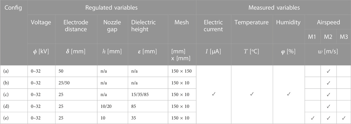
TABLE 1. Measurements overview.
3.3 Performance evaluation metrics
The operation range of the EHD air amplifier is primarily defined by its voltage-current characteristics. These characteristics show how much electric current is flowing at a specific voltage. By definition, the EHD air amplifier operation range starts when both an electric current and an airstream are measured. A Corona discharge may be measurable well before EHD air amplification occurs.
With the current-voltage (
Another measured value is velocity. At different locations, the value is taken from point probes anemometers. For the amplification mechanisms, we are interested in the volumetric flow rates [m3/s], which are estimated as
where
For this proof of concept study, the amplification factor is estimated here based on the air velocity measured at one point in the channel. For future optimization of the EHD air amplifier, measuring the air velocity profile via multiple point measurements or laser diagnostics (e.g., particle image velocimetry) would be beneficial. Furthermore, we assess the performance of EHD air amplification benchmarked to regular EHD and other airflow propulsion devices by the performance number γ, which has the units (m3/h)/W:
Commonly, the efficiency of fans is described by a fan pressure and flow rate curve (Onma and Chantrasmi, 2018). However, since the design of EHD focuses on creating thrust rather than pressure rise, we assess efficiency improvements in Eq. 4, also known as transduction efficiency. Comparing the transduction efficiency of EHD devices to conventional airflow generation devices is helpful, especially in application areas that require localized airflow generation, such as in drying (Onwude et al., 2021; Defraeye and Martynenko, 2018).
3.4 Statistical data evaluation
Three replications of the measurements are done, and the results are expressed as average ±standard deviation for electrical parameters. For flow-related measurements, the data is measured over 1 min. The results of flow speed are reported as min/max range. The results for flow rate are derived from the average of the velocity measurements. To obtain flow rate and flow rate to power characteristics, the results for flow rate are assisted by Local Polynomial Regression Fitting (LOESS) for display with a 0.95 confidence interval ribbon. The statistical analysis has been performed in (RStudio, 2022).
4 Results
4.1 EHD free field power demand for wire and needle
Figure 5 compares the electric power demand of both needle and wire for the EHD free field case, i.e., the base configuration with the large mesh at 50 mm spacing. The most apparent difference between needle and wire in power consumption is the EHD onset voltage. The needle can produce a measurable current and airflow at 9 kV. With the wire, the onsets at 15 kV. Both are similar in terms of power consumption, especially at higher voltages. Note that the EHD onset voltage differs from the Corona discharge onset voltage. The EHD onset voltage requires an airstream and an electric current to be non-zero. The Corona onset starts at 15 kV for the wire at lower voltages, and the power demand is about 70% lower than for needles. With a relatively sizeable inter-electrode gap of 50 mm, even a finer mesh would produce similar results. For engineering purposes, one would want to create a discharge at the lowest possible voltage to leave more room for finetuning the airflow.
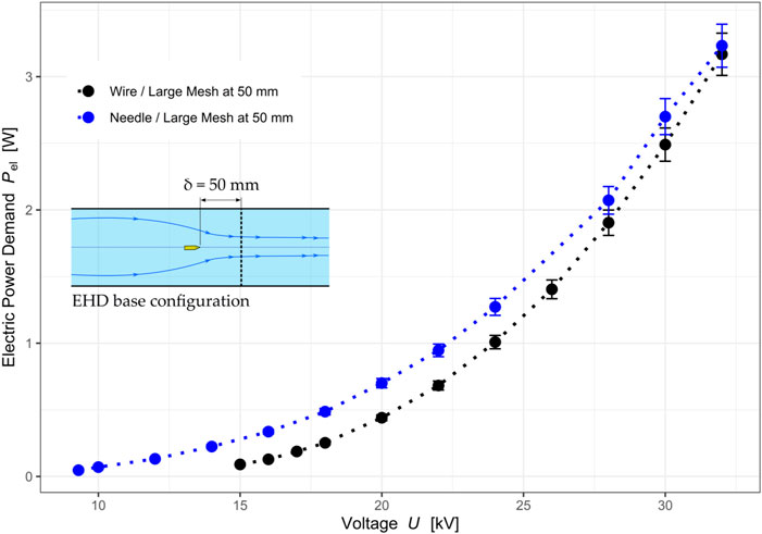
FIGURE 5. Power demand curves for the base configuration, i.e., free flow EHD. The wire consumes less power, but the EHD onset happens only after 15 kV, which decreases operational range.
4.2 Impact of reducing the collector electrode size on power demand
Figure 6 compares the results of configuration (b), where the influence of the electrode configuration is studied. Direct comparison between needle and wire emitter electrodes shows that needles consume more power, i.e., produce a more intense electric current. Similar behavior was also observed in the free field EHD configuration. Regarding the Corona onset voltage, the large mesh at a 50 mm distance behaves similarly to a small mesh at a 25 mm distance for both needles and wires. However, with increasing voltage, the differences in power consumption become more pronounced, i.e., small meshes at closer distances demand considerably more current. The wire/small mesh at 25 mm case reaches the spark-over voltage at 22 kV while its onset is at 15 kV. This case has the narrowest operation range and poses a handicap for successful EHD air amplification.
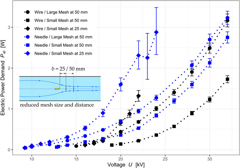
FIGURE 6. Power demand curves for configuration (b) with reduced mesh collector and distance. A more extensive voltage operation range for needles can be observed, especially at larger distances. Needles trigger EHD airflow below 10 kV at short distances, whereas the wire produces airflow at 15 kV. However, with the short distance, the Corona discharge tends to become unstable (as per error bars) at voltages above 21 kV. This phenomenon is more pronounced with the needle and small mesh at 25 mm. The instability at higher voltages emerges due to intensity variations in the electric field. The mesh collector consists of sufficiently thin wires that increasingly distort the potential distribution at such elevated voltages.
Another direct comparison between needle and wire cases for both small and large mesh at the same distance (50 mm) shows that the smaller mesh tends to reduce power demand, which agrees with general expectations as the number of conducting ground surfaces is reduced (Iranshahi et al., 2020). Here we can also observe that the power demand reduction from large to small mesh ground is considerably more significant for wire emitters than for needles. Needles react less sensitively to the size as they can transmit more power even in downsized electrode configurations. This observation is vital in the design of future downsized configurations. In summary, we can successfully reduce the collector size and should prefer, at this point, to use a needle emitter. The needle performs best for downsizing, yielding the most extensive operation range.
The role of the downstream mesh is significant and can affect both the electrostatic and airflow parts of EHD air amplification. We generally want the mesh to be as small as possible to reduce energy consumption and minimize flow resistance (Iranshahi et al., 2020). EHD air amplification is interesting because it minimizes flow disruptions while reducing energy consumption and increasing the flow rate.
4.3 Impact of dielectric material on discharge stability and operation range
The presence of a nearby dielectric, i.e., two acrylic glass plates as in case (C) in Figure 4, leads to a distortion of the electric field due to the different relative electric permeability (
The operation range is shown in Figure 7 through the current-voltage characteristics for the small mesh case. The most apparent difference between needle and wire is the shift in Corona onset voltage which starts at 9 kV for needles and 17 kV for the wire electrodes. Moreover, the discharge on the wire seems to suffer from the presence of the dielectric. The current magnitude decreases rapidly. This indicates that the electric field is distorted unfavorably for the wire setup. In principle, the electric field lines bend under the dielectric’s influence, so the ions’ propagation becomes more symmetric around the emitter. This causes the ions to accelerate toward the side walls, weakening the discharge stability due to the local accumulation of charges.
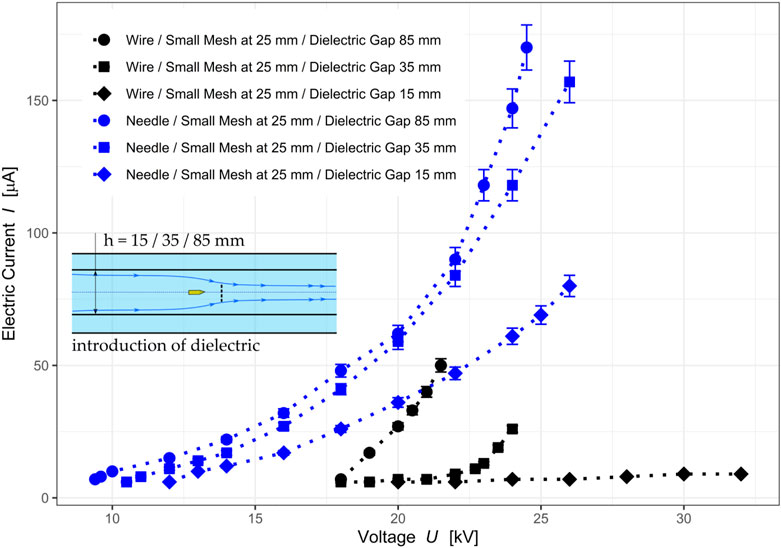
FIGURE 7. Voltage-current characteristics for configuration (C), including two acrylic glass plates at a variable gap distance. We note here that the dielectric has both a stabilizing and attenuation effect on the discharge. The attenuation is more pronounced on the wire electrode. The operation range is strongly reduced, and the discharge is impeded for the smallest dielectric ga On the other hand, the needle electrodes profit from the dielectric-dependent distortions in the electric field by emitting less charge and in a more stable way over the entire operating range.
On the other hand, needles are less affected by the presence of acrylic glass plates. The electric current reduces with an approaching dielectric, but it remains active. Also, the spark over voltage is at 24–26 kV, which leaves a spectrum of about 15 kV for the operation range (about three times larger than for wires).
Maintaining an extensive operation range regarding voltage and continuous production of ions is desirable. This is given for needles as they retain the best discharge stability. Hence, only needles are considered for the final EHD air amplification configuration, although wires initially seemed to provide lower electric power demand when sizing down the electrodes.
4.4 Impact of airflow contraction on the outlet velocity fluctuations
We must accelerate the airflow to create a Coanda effect and entrain airflow in the amplifier. The converging nozzle increases the outflow speed by contraction, poses a flow resistance, and decreases static pressure.
In Figure 8, the center speed at the outlet is reported for the 85 mm dielectric gap case with the nozzle at different sizes and without the nozzle. The measured velocity is a spread between the maximum and minimum observed velocity. The fields for needle and wire barely overla Both wire and needle have in common that the variation is considerable without a nozzle. Here, the needle emitter also proves more useful to generate faster speeds, which ultimately benefits air propulsion on a flat plate to produce EHD air amplification.
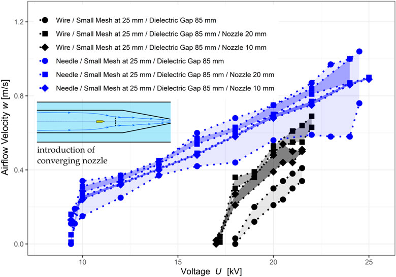
FIGURE 8. Airflow velocity at the outlet center of the channel. Without a nozzle, the air velocity varies over a more extensive range. A nozzle helps in reducing air velocity variations.
4.5 Proof of concept of EHD air amplification
This section will show that the Coanda effect triggers air amplification with EHD. Figure 9A reports the time-averaged air flow rates at measurement locations according to the sketch in Figure 4E. M3 is the point probe that tracks the amplified flow rates, i.e., the airflow generated due to the Coanda effect. M1 tracks the velocity within the EHD channel alone, while M2 is the total flow rate. The shaded areas represent the 0.95 confidence interval. For the EHD channel, the fluctuations are small in time, i.e., a constant inflow can be obtained.
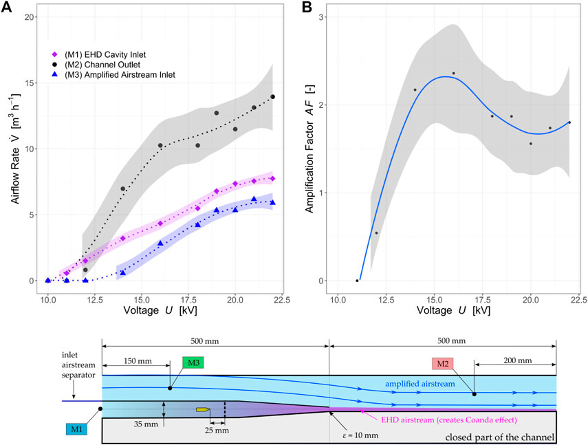
FIGURE 9. (A) Time-averaged airflow rates at three different EHD air amplifier configuration locations and (B) the resulting amplification factor.
The corona discharge onset voltage to measure the minimum airstream is 10 kV. Until 12 kV, the airflow at the inlet is dominant, and shortly after, M2 experiences a jump in flow rates. This is the point where EHD air amplification starts to develo At 16 kV, an airflow can also be measured at M3, thus proving the proof-of-concept that EHD air amplification is feasible. With the current setup, amplification factors of up to almost 3 are achieved, as seen in Figure 9B.
To benchmark EHD air amplification to regular EHD, the amplified airstream inlet is blocked, and the measurements are repeated. At location M3, for the benchmark case, zero airflows are measured. At outlet M2, the flow rate is compared to previously determined data. Figure 10 shows that EHDAA yields up to 75% efficiency gain compared to the regular EHD benchmark case. Also, we observe that the increasing current does not provide more substantial flow with increasing voltage. Instead, that stream dissipates electrical power without bringing additional momentum transfer. The reason is that EHD-generated flow scales with sufficient precision linearly with voltage while the power consumption exhibits a strong non-linearity with increasing voltage. Air amplification increases the flow rate after the Coanda effect establishes and thus significantly shifts the flow per power ratio. Hence, an efficiency maximum is achieved shortly after the Corona onset voltage. In summary, we can produce EHD air amplification with amplification factors of up to three. This is lower than current air amplifiers but is a start for further optimization.
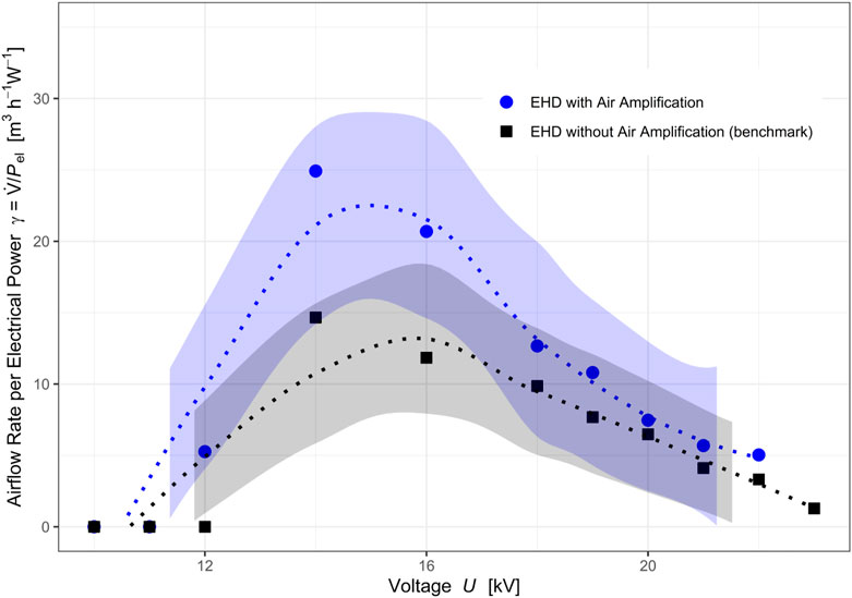
FIGURE 10. EHD air amplification benchmark against regular EHD without air amplification. The air amplification configuration yields up to a 66% efficiency increase.
5 Discussion
We analyzed in a step-wise manner the feasibility of EHD air amplification. To achieve EHD air amplification in this study, we used five rig configurations, two emitting electrode types, and two mesh electrode sizes. The arrangement and type of electrodes themselves offer vast optimization potential. We thus only explored a small set of the parametric space. This was sufficient for the study’s aim to show the proof of concept. The airflow speed and power consumption trends qualitatively match similar EHD-driven air blowers (Kanazawa et al., 2021).
In our study, the needle outperformed the wire as it allowed for a more extensive operation range due to its increased discharge stability. This superior stability is because needles have a more inhomogeneous electric field at the ti We could show that a nearby dielectric may impede the discharge. However, the needle maintains its inhomogeneity non-etheless. Therefore, we conclude that the needle is the most suitable emitter type for EHD air amplification. In free-flow EHD, the wire may be more efficient in generating flow rates. However, in EHD air amplification, we need to put the electrodes within a non-conducting enclosure which introduces homogeneities in the electric field. However, our study is limited to the proposed needle shape, and other shapes, tip curvatures, and distances may be more suitable. A comprehensive study featuring the needle geometry will be carried out.
On the airflow side, we showed a concept that achieves amplification factors up to 3. Other settings and arrangements, such as the number of needles or nozzle shapes, could potentially benefit from exploiting the Coanda effect. EHD air amplification operates at low pressures compared to conventional, pressurized-air amplifiers. However, this new way of combining EHD and the Coanda effect at low pressure also benefits energy-wise. For example, the peak energy efficiency is reached somewhere after the onset of Corona discharge and maintains a higher energy efficiency even with increasing flow rates.
To compare the benefits of EHD air amplification to state-of-art technologies, Table 2 gives an overview of the operation range of industrial and consumer air amplifiers and an axial fan (Type 5318/2 TDHHP, 66 W, 490 m3/h, ebm-papst St. Georgen GmbH, Hermann-Papst-Str. 1, D-78112 St. Georgen). The power demand Pd [W] of the Meech product is calculated assuming the compression of air as an ideal gas
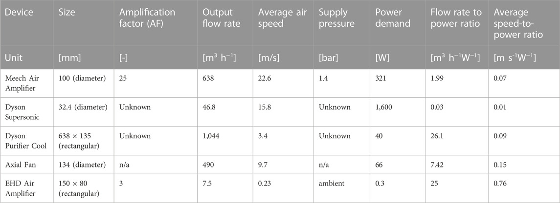
TABLE 2. Air amplification devices overview and axial fan for comparison.
Which estimates the power needed to raise the supplied airflow
Nevertheless, that is mainly due to its size. We obtain the average speed-to-power ratio when considering the device’s surface area. This metric makes comparison possible across all devices. The Dyson Purifier Cool does not perform significantly better than a pressurized air-fed air amplifier. It also underperforms compared to an axial fan. The EHD air amplifier in this study produces flow rates at a significantly lower energy cost.
For further comparison, EHD can also deliver a certain supply pressure, but this supply pressure is considerably lower than what we see for commercially established devices. An estimation of EHD pressure is possible via the following expression (Moreau et al., 2013)
with
By combining EHD with low-pressure air amplification technology, we aim to create a concept that increases the currently low energy conversion efficiency of EHD-driven devices. EHD air amplification outperforms even an axial fan in this example. Moreover, EHD air amplification retains the benefits of corona discharge, e.g., ozone production, which can interest decontamination applications.
6 Conclusion
We experimentally investigated a novel concept called Electrohydrodynamic (EHD) air amplification, intending to increase EHD-generated airflow rates to make EHD-based devices more attractive, low-energy, and customizable airflow sources. So far, improvements in EHD airflow generation have focused on electrode arrangements. Our study is the first to combine EHD with air amplification to ramp up flow rates and increase overall aerodynamic performance. Unlike conventional air amplifiers fed by pressurized air, EHD air amplification operates at atmospheric pressure. Our key findings from this experimental study demonstrate the feasibility and potential to generate higher EHD-based flow rates with little energy input.
• We experimentally proved the EHD air amplification concept. Our 150 × 150 × 1,000 mm3 channel test rig produces up to 15 m3/h of silent and vibrationless airflow, up to three times more than regular EHD generates for the same electrical cost of less than 3 W.
• Needle electrodes outperform wire electrodes in terms of discharge stability. The EHD operation range for wires is 16–24 kV, and for needles, it is 9–25 kV (+100%).
• Dielectrics near the discharge electrodes drastically reduce the power demand by lowering the electric current flow. Wire electrodes may even cease operation as their discharge onset shifts towards higher voltages (17 kV), while needle electrodes keep producing current from 9 kV on (−52%).
• The peak energy performance in flow rate per electrical power invested substantially increases from 15 to 25 (m3/h)/W (+66%) compared to a non-amplifying EHD benchmark.
This experimental study demonstrates the feasibility and potential to generate higher EHD-based flow rates with little energy input. Our approach reduces the collector size, which poses a flow resistance and also increases power consumption. Instead, we utilize the EHD-airstream that we generate as a bleed stream, which can be used to induce a larger flow via the Coanda effect. This allows us to increase flow rates without incurring any additional electrical costs. Upcoming studies focus on optimizing EHD air amplifiers to increase flow rates further while reducing energy consumption. In this regard, we will also consider EHD air amplifiers for external flows, further improving our solution by exploiting the Coanda effect. EHD air amplification is a constructively simple and scalable technology to customize airflow patterns at a low energy cost, thus, enabling the improvement of ventilation systems.
Data availability statement
The raw data supporting the conclusions of this article will be made available by the authors, without undue reservation.
Author contributions
DR: Conceptuatlization, Methodology, Investigation, Project Management, Writing—review and editing. KI: Methodology, Writing—review and editing. DO: Writing—review and editing. LX: Methodology, Writing—review and editing. BN: Writing—review and editing. TD: Conceptualization, Methodology, Supervision, Funding procurement, Project Management, Writing—review and editing.
Funding
Swiss Innovation Agency (Innosuisse 34549.1 IP-LS) Belimed AG. Open access funding by Swiss Federal Laboratories for Materials Science and Technology (Empa).
Acknowledgments
The authors are grateful to the Swiss Innovation Agency (Innosuisse 34549.1 IP-LS) and Belimed AG for the financial support provided during project conceptualization and execution.
Conflict of interest
LX was employed by Belimed AG.
The remaining authors declare that the research was conducted in the absence of any commercial or financial relationships that could be construed as a potential conflict of interest.
Publisher’s note
All claims expressed in this article are solely those of the authors and do not necessarily represent those of their affiliated organizations, or those of the publisher, the editors and the reviewers. Any product that may be evaluated in this article, or claim that may be made by its manufacturer, is not guaranteed or endorsed by the publisher.
References
Ambaw, A., Verboven, P., Delele, M. A., Defraeye, T., Tijskens, E., Schenk, A., et al. (2014). CFD-based analysis of 1-MCP distribution in commercial Cool store rooms: Porous medium model application. Food Bioprocess Technol. 7 (7), 1903–1916. doi:10.1007/s11947-013-1190-9
Bashkir, I., and Martynenko, A. (2021). Optimization of multiple-emitter discharge electrode for electrohydrodynamic (EHD) drying. J. Food Eng. 305, 110611. doi:10.1016/J.JFOODENG.2021.110611
Chua, K. J., Chou, S. K., Yang, W. M., and Yan, J. (2013). Achieving better energy-efficient air conditioning – a review of technologies and strategies. Appl. Energy 104, 87–104. doi:10.1016/J.APENERGY.2012.10.037
Colas, D. F., Ferret, A., Pai, D. Z., Lacoste, D. A., and Laux, C. O. (2010). Ionic wind generation by a wire-cylinder-plate corona discharge in air at atmospheric pressure. J. Appl. Phys. 108 (10), 103306. doi:10.1063/1.3514131
Defraeye, T., and Martynenko, A. (2018). Electrohydrodynamic drying of food: New insights from conjugate modeling. J. Clean. Prod. 198, 269–284. doi:10.1016/j.jclepro.2018.06.250
Dumitrache, A., Frunzulica, F., and Ionescu, T. C. (2012). “Mathematical modelling and numerical investigations on the Coanda effect,” in Nonlinearity, bifurcation and chaos - theory and applications (London: InTech).
Iranshahi, K., Martynenko, A., and Defraeye, T. (2020). Cutting-down the energy consumption of electrohydrodynamic drying by optimizing mesh collector electrode. Energy 208, 118168. doi:10.1016/j.energy.2020.118168
Jewell-Larsen, N. E., Joseph, G. G., and Honer, K. A. (2011). “Scaling laws for electrohydrodynamic air movers,” in ASME/JSME 2011 8th Thermal Engineering Joint Conference, USA, March 13–17, 2011.
Jewell-Larsen, N. E., Tran, E., Krichtafovitch, I. A., and Mamishev, A. V. (2006). Design and optimization of electrostatic fluid accelerators. IEEE Trans. Dielectr. Electr. Insulation 13 (1), 191–203. doi:10.1109/TDEI.2006.1593417
Johnson, M. J., Tirumala, R., and Go, D. B. (2015). Analysis of geometric scaling of miniature, multi-electrode assisted corona discharges for ionic wind generation. J. Electrost. 74, 8–14. doi:10.1016/J.ELSTAT.2014.12.001
Kanazawa, S., Imagawa, W., Matsunari, S., Akamine, S., Ichiki, R., and Kanazawa, K. (2021). Ionic wind devices prepared by a 3D printer. Available at: https://ijpest.securesite.jp/Contents/11/1/PDF/11-01-038.pdf.
Lai, F. C. (2020). EHD gas pumping – a concise review of recent development. J. Electrost. 106, 103469. doi:10.1016/J.ELSTAT.2020.103469
Moreau, E., Benard, N., Lan-Sun-Luk, J. D., and Chabriat, J. (2013). Electrohydrodynamic force produced by a wire-to-cylinder dc corona discharge in air at atmospheric pressure. J. Phys. D. Appl. Phys. 46 (47), 475204. doi:10.1088/0022-3727/46/47/475204
Onma, P., and Chantrasmi, T. (2018). Comparison of two methods to determine fan performance curves using computational fluid dynamics. IOP Conf. Ser. Mater. Sci. Eng. 297 (1), 012026. doi:10.1088/1757-899X/297/1/012026
Onwude, D. I., Iranshahi, K., Rubinetti, D., Martynenko, A., and Defraeye, T. (2021). Scaling-up electrohydrodynamic drying for energy-efficient food drying via physics-based simulations. J. Clean. Prod. 329, 129690. doi:10.1016/J.JCLEPRO.2021.129690
Panitz, T., and Wasan, D. T. (1972). Flow attachment to solid surfaces: The Coanda effect. AIChE J. 18 (1), 51–57. doi:10.1002/aic.690180111
Rickard, M., Dunn-Rankin, D., Weinberg, F., and Carleton, F. (2006). Maximizing ion-driven gas flows. J. Electrost. 64 (6), 368–376. doi:10.1016/j.elstat.2005.09.005
Rstudio (2022). RStudio | Open source & professional software for data science teams - RStudio. Available at: https://www.rstudio.com/ (Accessed March 03, 2022).
Tirumala, R., and Go, D. B. (2011). Multi-electrode assisted corona discharge for electrohydrodynamic flow generation in narrow channels. IEEE Trans. Dielectr. Electr. Insulation 18 (6), 1854–1863. doi:10.1109/TDEI.2011.6118623
Wang, H. C., Jewell-Larsen, N. E., and Mamishev, A. V. (2013). Thermal management of microelectronics with electrostatic fluid accelerators. Appl. Therm. Eng. 51 (1–2), 190–211. doi:10.1016/j.applthermaleng.2012.08.068
Wang, T. H., Shen, B., Zhao, H., Wang, L., and You, M. Y. (2023). Local hotspot thermal management improved by ionic wind generator coupled with porous materials. Int. J. Therm. Sci. 184, 107878. doi:10.1016/J.IJTHERMALSCI.2022.107878
Keywords: air amplification, alternative air propulsion, ionic wind, corona discharge, low power ventilation
Citation: Rubinetti D, Iranshahi K, Onwude D, Nicolaï B, Xie L and Defraeye T (2023) Electrohydrodynamic air amplifier for low-energy airflow generation—An experimental proof-of-concept. Front. Energy Effic. 1:1140586. doi: 10.3389/fenef.2023.1140586
Received: 09 January 2023; Accepted: 10 March 2023;
Published: 31 March 2023.
Edited by:
Sarat Kumar Sahoo, Parala Maharaja Engineering College (M.E.C), IndiaReviewed by:
Selcuk Selimli, Karabük University, TürkiyeVictorita Radulescu, Polytechnic University of Bucharest, Romania
Copyright © 2023 Rubinetti, Iranshahi, Onwude, Nicolaï, Xie and Defraeye. This is an open-access article distributed under the terms of the Creative Commons Attribution License (CC BY). The use, distribution or reproduction in other forums is permitted, provided the original author(s) and the copyright owner(s) are credited and that the original publication in this journal is cited, in accordance with accepted academic practice. No use, distribution or reproduction is permitted which does not comply with these terms.
*Correspondence: Thijs Defraeye, dGhpanMuZGVmcmFleWVAZW1wYS5jaA==