 Osama Mazhar
 Ahmad Zawawi Jamaluddin
 Cansen Jiang
 David Fofi
 Ralph Seulin
 Olivier Morel
- Le2i FRE2005, CNRS, ENSAM, Université de Bourgogne Franche-Comté, Le Creusot, France
It has been observed in the nature that all creatures have evolved highly exclusive sensory organs depending on their habitat and the form of resources availability for their survival. In this project, a novel omnidirectional camera rig, inspired from natural vision sensors, is proposed. It is exclusively designed to operate for highly specified tasks in the field of mobile robotics. Navigation problems on uneven terrains and detection of the moving objects while the robot is itself in motion are the core problems that omnidirectional systems tackle. The proposed omnidirectional system is a compact and a rigid vision system with dioptric cameras that provide a 360° field of view in horizontal and vertical, with no blind spot in their site combined with a high-resolution stereo camera to monitor anterior field of view for a more accurate perception with depth information of the scene. Structure from motion algorithm is adapted and implemented to prove the design validity of the proposed camera rig, and a technique is developed to calibrate similar systems.
1. Introduction
The rapid development in computing systems, and their availability to the consumer market, soon made researchers realize that computational inability may not necessarily be the only handicap in all scientific problems. If observed in nature, all creatures have evolved very unique and highly specified anatomical and physiological traits that depend on the habitat they live and the availability of the resources their survival is dependent on. Moreover, in the field of computer vision, sensors with larger field of view are always appreciated. These are specialized systems that enable to acquire more information with less equipment/image-data used. Omnidirectional or panoramic cameras have become an affordable and popular photographic tool that allows to capture 360° panoramic images (Knill and Ramirez-Herran, 2007).
The applications of the omnidirectional cameras are, but not limited to, robot localization and mapping (Hart, 2014; Kim et al., 2014; Liu and Siegwart, 2014; Lukierski et al., 2015), robot navigation (Zhang et al., 2012; Watanabe et al., 2013; Delgado-Galvan et al., 2015; Hart et al., 2015), object tracking (Cogal et al., 2014; Depraz et al., 2015; Sablak, 2015), visual servoing (Caron et al., 2013; Liu et al., 2013; Marković et al., 2014; Pasteau et al., 2016), structure from motion (Chang and Hebert, 2000; Micusik and Pajdla, 2006; Kawanishi et al., 2008; Kim and Oh, 2008), and virtual reality/visual telepresence (Li et al., 2013; Kawauchi and Rekimoto, 2014; Kasahara and Rekimoto, 2015).
1.1. Proposed System
An omnivision camera rig has been developed (see Figure 1) using two fisheye cameras with field of view of approximately 185° each, which are fixed opposite to each other facing laterally, so as to cover 360° in horizontal and vertical (Jamaluddin et al., 2016). A depth camera, namely “ZED Camera,” is also mounted in front of the rig that covers the anterior view providing high-resolution RGB + depth image (StereoLabs, 2016).
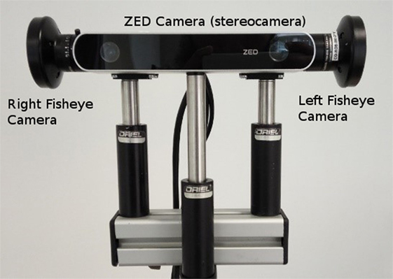
Figure 1. The proposed Polydioptric Camera Rig.
1.2. Concept and Motivation
It is observed that creatures in nature are divided into two categories: preys and predators (Paine, 1966). The first category, i.e., preys, usually have eyes on lateral sides of their heads covering a larger field of view as to detect any danger easily. They need not to have a higher resolution or larger field with depth information, as their main purpose is to detect and mostly running away to a safer place. However, predators have eyes mostly on their anterior portion of their heads, though with a limited field of view, but have a larger depth information in contrast to earlier. In this reference, a vision system is designed, with capabilities of that of both. This system may be used for several tasks as stated before, including the tasks related to navigating on an uneven terrain or detecting the movements of other objects while the robot with this camera rig is moving itself.
1.3. Paper Outline
A brief background of omnivision systems is discussed in Section 2, camera model and the epiploar geometry adapted for omnidirectional cameras are explained in Section 3, calibration of the camera rig and scene reconstruction are presented in Section 4, and Section 5 concludes the article.
2. Background
2.1. Omnidirectional Cameras
Omnidirectional cameras can be mainly designed as either dioptric systems [assisting vision by refracting and focusing (Neumann et al., 2003)] or catadioptric systems (dioptric imaging that incorporates reflecting surfaces (Gluckman and Nayar, 1998) or mirrors; see Figure 2). However, polydioptric cameras may also be considered as another category of the vision systems which will be discussed in a section to come. The camera systems can be classified into two categories determined by whether they do have a unique effective viewpoint or not (Geyer and Daniilidis, 2000).
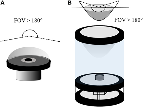
Figure 2. Illustration of (A) dioptric (fisheye) camera and (B) catadioptric camera.
For any vision system, it is highly anticipated that there exists a single effective viewpoint. It allows to extract pure perspective images from the image taken by such a camera system (see Figure 3). The images taken from these camera systems preserve the linear perspective geometry. The uniqueness of the viewpoint is equivalent to a purely rotating planar camera all of whose viewpoints coincides (Geyer and Daniilidis, 2000). Hence for omnidirectional cameras having a single viewpoint allows to extract not only perspective but also panoramic images without the knowledge of depth of the scene (Nayar, 1997). Also the single viewpoint allows to map the images produced by the vision system onto a sphere (Gluckman and Nayar, 1998).
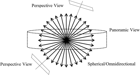
Figure 3. Illustration of a sphere of view for a true omnidirectional image; figure inspired by Nayar (1997).
Conical, spherical and most fisheye cameras do not have a unique effective viewpoint. Nayar and Baker have investigated the cases of catadioptric cameras by Nayar (1997), which led to a conclusion that only two practical solutions exist for the reflecting surfaces, the hyperbolic and elliptical systems. However by Nayar (1997), it is shown that the parabolic mirrors with orthographic projections (paracatadioptric system) can also be used to achieve a single viewpoint. Meanwhile elliptical mirrors in fact only reduce the field of view, so they are not used in practice. Hyperbolic and parabolic catadioptric cameras are able to capture at least a hemisphere of the scene from a unique viewpoint.
2.2. Polydioptric Cameras
In order to enhance the capability of the vision system, designs with multiple cameras were proposed by Neumann et al. (2003), thus a term evolved namely a polydioptric camera. The authors describe polydioptric camera as “a generalized camera that captures a multiperspective subset of the space of light rays.” There are several examples for such modalities emerged especially with the development of portable and computational devices such as mobile phones and wireless communication systems.
2.3. Spherical Approximation of Multiple Cameras
Although polydioptric/multiple cameras are used either to have a stereo-vision capability or to enhance the vision system field of view, it is impossible for such a camera rig to have a single effective viewpoint because of physical real-life constraints, e.g., sensor size and bulky camera mounting. In this case, any motion estimation or structure from motion algorithm might simply fail. In the study by Kim et al. (2010), authors not only proposed a solution for this problem by spherical approximation of multiple cameras but also demonstrated that this approximation outperforms the generalized camera model when the features of interest are sufficiently farther when compared with the baseline of the cameras.
3. Methodology
3.1. Camera Model
The efforts to design a vision system with larger field of view arose several different modalities as discussed in Section 2.1, whose geometry cannot be described using the conventional pinhole model. A unified projection model for the entire class of central catadioptric systems (catadioptric vision system with single effective viewpoint) has been proposed. It explains that all central catadioptric systems can be modeled by a central projection of a point in the space onto the unit sphere followed by another central projection from a point lying between the sphere center and its north pole onto the image plane (Geyer and Daniilidis, 2000). The fisheye cameras, as said earlier, do not have a single effective viewpoint (see Figure 4) instead have a locus of projection centers (diacaustic). Nevertheless in Barreto (2006a,b), it is demonstrated that the small locus of dioptric systems can be approximated by a single viewpoint and thus these systems also underlie a common central projection model.
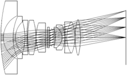
Figure 4. A full-frame fisheye lens layout; invented by T. Ogura, Assignee: Minolta, US Patent 3589798, Date: June 29, 1971 (layout released by Coastal Optical Systems, Inc.) (Kumler and Bauer, 2000).
Mei and Rives (2007) proposed a model for all single viewpoint omnidirectional cameras and developed a toolbox for camera calibration using planar grids as for conventional cameras. This model is an extension of the model proposed by Barreto and Geyer (Geyer and Daniilidis, 2000; Barreto, 2006b) and differs only with respect to some minor differences in conventions regarding the direction of the camera, addition of tangential distortion parameters, and projecting the three-dimensional points in space onto a sphere instead of a paraboloid. This model anticipates the distortions in the fisheye image and describes a parameter E that determines the amount of radial distortion. This also considers the projection of the scene onto a unit sphere, thus allows to exploit the spherical approximation for a polydioptric camera rig, as in our case. We opt for this model to be followed in this project.
3.2. Omnidirectional Epipolar Geometry
The epipolar geometry for panoramic cameras is studied by Svoboda et al. (1998) for hyperbolic mirror. In this case, a simpler mathematical formulation proposed by Chang and Hebert (2000), originally for catadioptric cameras, is adapted for dioptric systems. The epipolar constraints for fisheye cameras are shown in Figure 5. P is a point in the scene, P1 and P2 are its projections onto the unit spheres, and (u1, v1) and (u2, v2) are its corresponding image coordinates on the two fisheye images. The projections onto the unit sphere are computed as by Mei and Rives (2007). From the figure, it can be observed that P, P1, P2, O1, and O2 are coplanar, hence we get,
where and are the coordinates of O1 and P1 in coordinate system X2, Y2, and Z2. The rigid motion between X1, Y1, and Z1 and X2, Y2, and Z2 can be described by rotation R and translation t. The transformation equations can be written as,
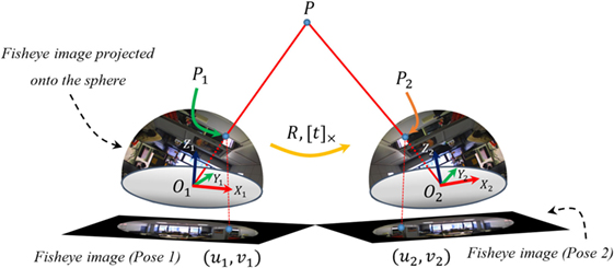
Figure 5. Epipolar geometry of the fisheye cameras.
Substituting (2) in (1) we get,
where E = [t]× R is the essential matrix which may be decomposed into the motion parameters. If a set of point correspondence is given such that i = 1, …, n, where n ≥ 7 and mi = [ui, vi] are the image coordinates of fisheye camera, essential matrix can be computed by minimizing the epipolar errors. In order to estimate the essential matrix, the point correspondence pairs are stacked into one linear system, thus the overall epipolar constraint becomes,
where
and ui and f are vectors constructed by stacking columns of matrices Pi and E, respectively.
The essential matrix can be estimated with linear least square by solving Equations (4) and (5), where is the projected point, which corresponds to P2 of the Figure 5, U is a n × 9 matrix and f is 9 × 1 vector containing the 9 elements of E. The initial estimate of essential matrix is then exploited for the robust estimation of essential matrix. A modified iteratively reweighted least square method for omnivision cameras, originally explained by Torr and Murray (1997), is then proposed. This assigns minimal weights to the outliers and noisy correspondences. The weight assignment is performed by finding the residual ri for each point.
where wsi is the weight (known as Sampson’s weighting) that will be assigned to each set of corresponding point and ∇ri is the gradient; rxi and so on are the partial derivatives found from Equation (6) as .
Once all the weights are computed, U matrix is updated as follow,
where W is a diagonal matrix of the weights computed using Equation (8). The essential matrix is estimated at each step and forced to be of rank 2 in each iteration. The procrustean approach is adopted here, and singular value decomposition is used for this purpose.
4. Results
4.1. Intrinsic Camera Calibration
The estimation of the intrinsic parameters of the fisheye cameras is performed using the study by Mei and Rives (2007), and the images are projected onto the unit sphere using the equations provided by the aforementioned camera model. The value of ξ (eccentricity) plays an important role to determine the extent of enfolding the image onto the unit sphere. It leads to the need to develop a set-up for robust estimation of ξ up to the required accuracy.
4.1.1. Re-estimation of ξ
The baseline of the camera rig (distance between the centers of the left and right fisheye lens) is measured, and two parallel lines with the same distance to each other as well as a center line are drawn on a pattern. The rig is faced and aligned in front of the pattern such that the center line touches the edges of both circular fisheye camera images (see Figures 6 and 7). The parallel line corresponding to the edge of fisheye lens of each camera is then forced to the zero plane when the fisheye image is projected onto the unit sphere. This is done by developing a cost function to estimate ξ that minimizes the z-component of pixels on the selected line using internal point optimization algorithm.
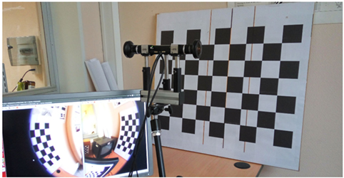
Figure 6. Setup for re-estimating ξ.
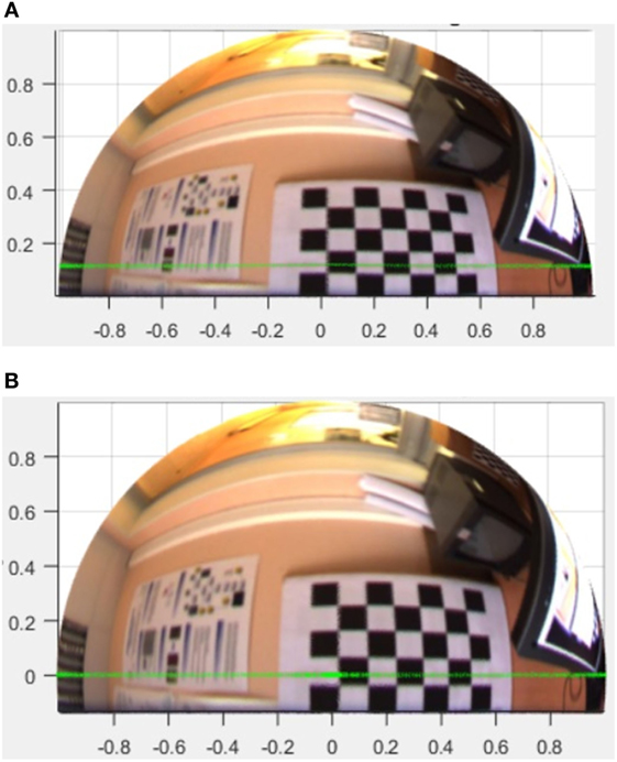
Figure 7. (A,B) illustrate the iterative estimation of ξ for optimum enfolding of the fisheye images. (A) Fisheye image projected onto unit sphere with initial ξ estimate. (B) The 180° line now lie on the zero plane after iterative estimation of ξ.
4.2. Estimation of Extrinsic Parameters of the Rig
4.2.1. Rigid Transformation Estimation
The estimation of rigid transformation of non-overlapping cameras has been discussed by Lébraly et al. (2010). However, since our camera system has an approximately 5° of overlap along the periphery of two hemispheres, we decided to use the overlapping features to estimate the transformation between two cameras. The matching points in two fisheye camera images are selected manually. The selected points are then projected onto the unit sphere with the calibration results obtained earlier. Interior point optimization algorithm from Kim et al. (2007) is used to iteratively estimate pure rotation between the set of projected points; thus a transformation with pure rotation is obtained.
The same procedure is repeated to find pure rotation between the sphere from fisheye cameras and the stereo camera. The transformation result is shown in Equation (12).
4.2.2. Estimation of Overlap between Fisheye and Stereo Camera
To perform tasks such as object detection and object tracking, estimating the portion of omnidirectional unit sphere which is mutually covered by high-resolution RGB-D information from the ZED camera, is highly substantial. The boundary pixels of the ZED camera image are first projected onto the unit sphere and then k-Nearest-Neighbor (kNN) algorithm is used to find the overlapping pixels of the fisheye sphere with them. The overlapping pixels from the unit sphere projection of the fisheye images are then projected back onto the image plane using the camera model as in Mei and Rives (2007). Figure 8 shows the approximate overlapping field of view of fisheye cameras and ZED camera.
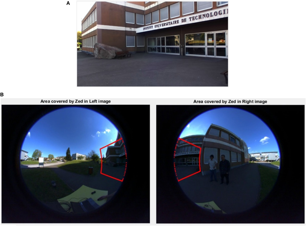
Figure 8. Finding the overlapping image pixels (field of view) in fisheye images and in high-resolution image of stereo camera. (A) High-resolution image from the stereo camera. (B) Overlapping field of view is defined by the area inside the red boundaries (informed and written consent has been obtained from the subjects for the publication of this image).
4.2.3. Fusion of Images (Spherical Approximation)
The transformation matrices (actually rotation matrices) obtained as in Equations (11) and (12) are used to fuse the two hemispheres from the fisheye camera and the projection of the high-resolution RGB + D image from stereo camera onto the unit sphere (see Figure 9).
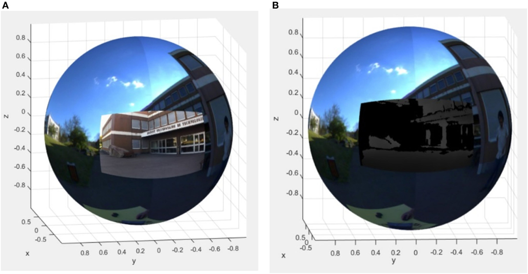
Figure 9. The omnivision sphere after the fusion of fisheye image hemispheres with high-resolution RGB and depth image unit sphere projections from the stereo camera. (A) Fused high-resolution RGB image and the sphere. (B) Fused depth image and the sphere.
4.3. Scene Reconstruction Using Omnidirectional Cameras
The scene can be reconstructed and point P can be triangulated using the parameters P1, P2, R, and t as discussed by Ma et al. (2015). Observing Figure 5, the line passing through O1 and P1 can be defined as aP1 and the line passing through O2 and P2 can be defined as bRP2 + t in the reference frame O1; where a, b ∈ R. The goal of triangulation is to minimize the distance between two lines, thus the problem can be expressed as a least square problem.
The three-dimensional point P is reconstructed by finding the middle point of the minimal distance between the lines aP1 and bRP2 + t as follows:
This triangulation method is applicable for all possible solutions. The conventional criteria to select the optimal solution which gives the positive depth of the reconstructed points is unsuitable in this case because of special geometrical properties of this method. A novel method is proposed to solve the problem of ambiguity of the results which is described as follows.
The scene is reconstructed using each of the four possible solutions and we get four sets of reconstructed points ; where i = 1, 2, 3, 4. As already mentioned, the first step for reconstruction of the scene is to capture at least two real images, select the matching points in two-dimensional images and “project the selected points onto the unit sphere” using the equations proposed in the spherical camera model. So for scene reconstruction, we already have at least two set of points projected onto the unit sphere. The projection of points onto the unit sphere at the first pose Ps will be used in the later steps.
All four reconstructed sets are considered one at a time and each point in each set is divided by its norm. As a result we get more unit sphere projections, one for each reconstructed set. Ideally, the distance between the normalized true reconstructed points and the points projected onto the unit sphere of the first pose of camera Ps should be zero, denoted as:
This distance is evaluated for each solution and the one that gives the least distance is considered the optimal solution. This technique is implemented on synthetic as well as real data, and the result is optimum in all cases.
4.4. Error Analysis
The quantification of error is done by creating synthetic data and comparing the reconstructed points with the synthetic input. Gaussian noise is introduced with multiples of standard deviation which is equal to the largest pixel to pixel distance over the spherical projection. Several patterns of input data were generated and two of them with there reconstructed points are shown in Figure 10.
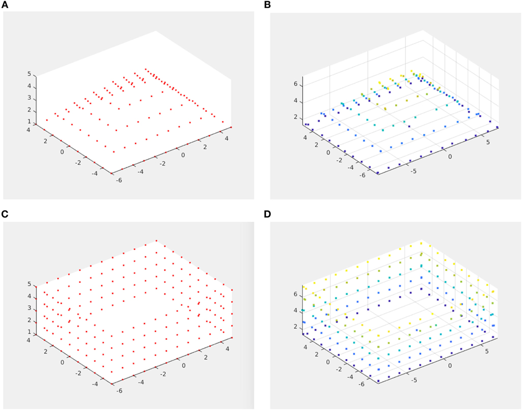
Figure 10. Three-dimensional scene reconstruction using synthetic data. (A) Synthetic data (pyramid) with noise 0.002 standard deviations. (B) Reconstructed pyramid. (C) Synthetic data (wall) with noise 0.001 standard deviations. (D) Reconstructed wall.
The error plot is shown in Figure 11, where average Euclidean distance of 50 trials is plotted for each value of standard deviation (0.005) with 50 multiples of 0.05 for pyramid reconstruction. This error pattern is consistent with other synthetic three-dimensional patterns also.
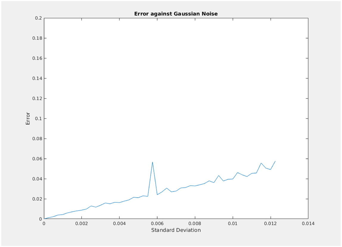
Figure 11. Euclidean distance plot between synthetic ground truth and reconstruction for multiple standard deviations.
5. Conclusion
A technique is developed for the extrinsic calibration of the proposed camera rig and similar vision systems with overlapping field of view. The spherical model of camera is exploited because several image processing algorithms have already been developed based on this model for catadioptric cameras, which can be implemented on the results obtained by our camera rig. The images from all the cameras are projected onto the unit sphere and fused to follow spherical approximation for polydioptric cameras. The estimation of essential matrix and scene reconstruction by the proposed adaptation of epipolar geometry and triangulation method is performed on synthetic data with Gaussian noise and standard deviation equal to a multiple of the largest pixel to pixel distance over the spherical projection. The results are compared with the ground-truth that is computed from known rotation and translation, and the adaptation of epipolar geometry to the spherical model is found promising. The results are also computed for real images with automatic feature extraction as described by Harris and Stephens (1988), Lowe (2004), Bay et al. (2006), and Donoser and Bischof (2006) and with manual point selection also (see Figures 12 and 13).
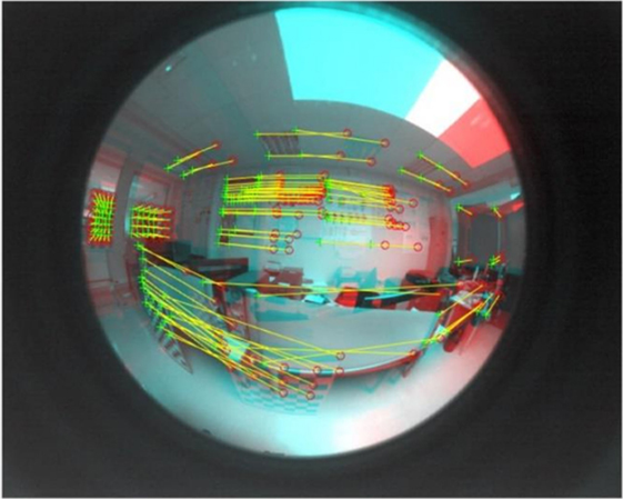
Figure 12. Feature matching between two poses of the fisheye camera.
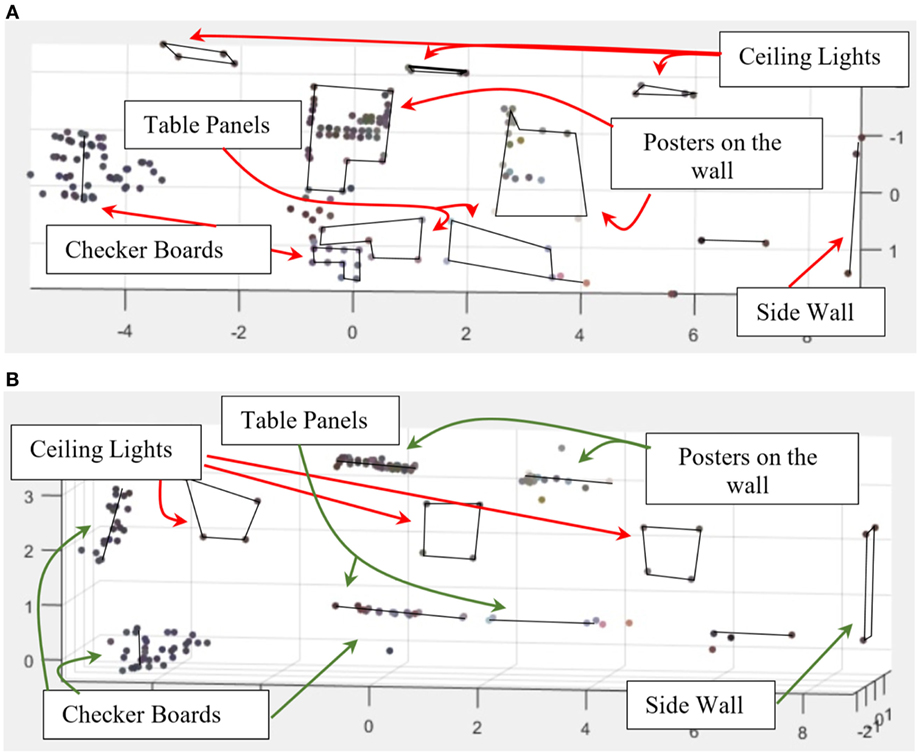
Figure 13. (A,B) show the result of scene reconstruction algorithm developed following the spherical model of the camera. (A) Front view of the reconstructed scene. (B) Top view of the reconstructed scene.
Author Contributions
DF, RS, and OM jointly conceived and supervised the proposed design. AZJ collected the data. OM performed necessary experiments, developed the code, and wrote the article. CJ helped in developing several parts of the code and in realization of Section 4.1.1. All authors discussed the results and observations and commented on the manuscript at all stages.
Conflict of Interest Statement
The authors declare that the research was conducted in the absence of any commercial or financial relationships that could be construed as a potential conflict of interest.
Funding
This work is part from a project entitled VIPeR (Polarimetric Vision Applied to Robotics Navigation) funded by the French National Research Agency ANR-15-CE22-0009-VIPeR.
References
Barreto, J. P. (2006a). A unifying geometric representation for central projection systems. Comput. Vis. Image Underst. 103, 208–217. doi: 10.1016/j.cviu.2006.06.003
Barreto, J. P. (2006b). “Unifying image plane liftings for central catadioptric and dioptric cameras,” in Imaging Beyond the Pinhole Camera (Netherlands: Springer), 21–38.
Bay, H., Tuytelaars, T., and Van Gool, L. (2006). “Surf: speeded up robust features,” in European Conference on Computer Vision (Berlin: Springer), 404–417.
Caron, G., Marchand, E., and Mouaddib, E. M. (2013). Photometric visual servoing for omnidirectional cameras. Auton. Robots 35, 177–193. doi:10.1007/s10514-013-9342-3
Chang, P., and Hebert, M. (2000). “Omni-directional structure from motion,” in Proceedings of the IEEE Workshop on Omnidirectional Vision, 2000 (Hilton Head Island: IEEE), 127–133.
Cogal, O., Akin, A., Seyid, K., Popovic, V., Schmid, A., Ott, B., et al. (2014). “A new omni-directional multi-camera system for high resolution surveillance.” in Proc. SPIE. 91200N, San Diego, CA, USA.
Delgado-Galvan, J., Navarro-Ramirez, A., Nunez-Varela, J., Puente-Montejano, C., and Martinez-Perez, F. (2015). “Vision-based humanoid robot navigation in a featureless environment,” in Mexican Conference on Pattern Recognition (Mexico City: Springer), 169–178.
Depraz, F., Popovic, V., Ott, B., Wellig, P., and Leblebici, Y. (2015). “Real-time object detection and tracking in omni-directional surveillance using gpu,” in SPIE Security+ Defence, eds K. U. Stein and R. H. M. A. Schleijpen (Toulouse: International Society for Optics and Photonics), 96530N.
Donoser, M., and Bischof, H. (2006). “Efficient maximally stable extremal region (mser) tracking,” in IEEE Computer Society Conference on Computer Vision and Pattern Recognition, 2006, Vol. 1 (Netherlands: IEEE), 553–560.
Geyer, C., and Daniilidis, K. (2000). “A unifying theory for central panoramic systems and practical implications,” in European Conference on Computer Vision (Berlin, Heidelberg: Springer), 445–461.
Gluckman, J., and Nayar, S. K. (1998). “Ego-motion and omnidirectional cameras,” in Sixth International Conference on Computer Vision, 1998 (Bombay: IEEE), 999–1005.
Harris, C., and Stephens, M. (1988). “A combined corner and edge detector,” in Alvey Vision Conference, Vol. 15 (Manchester, UK: Citeseer), 10–5244.
Hart, C. (2014). A Low-Cost Omni-Directional Visual Bearing Only Localization System. PhD thesis, Case Western Reserve University.
Hart, C., Kreinar, E., Chrzanowski, D., Daltorio, K. A., and Quinn, R. D. (2015). “A low-cost robot using omni-directional vision enables insect-like behaviors,” in 2015 IEEE International Conference on Robotics and Automation (ICRA) (Seattle, WA: IEEE), 5871–5878.
Jamaluddin, A. Z., Mazhar, O., Morel, O., Seulin, R., and Fofi, D. (2016). “Design and calibration of an omni-rgb+ d camera,” in 13th International Conference on Ubiquitous Robots and Ambient Intelligence (URAI), 2016 (Xi’an: IEEE), 386–387.
Kasahara, S., and Rekimoto, J. (2015). “Jackin head: immersive visual telepresence system with omnidirectional wearable camera for remote collaboration,” in Proceedings of the 21st ACM Symposium on Virtual Reality Software and Technology (Beijing: ACM), 217–225.
Kawanishi, R., Yamashita, A., and Kaneko, T. (2008). “Construction of 3d environment model from an omni-directional image sequence,” in Proceedings of the 3rd Asia International Symposium on Mechatronics, TP1-3 (2) (Sapporo), 1–6.
Kawauchi, K., and Rekimoto, J. (2014). “Quantized reality: automatic fine-grained spherical images acquisition for space re-construction,” in Proceedings of the 13th ACM SIGGRAPH International Conference on Virtual-Reality Continuum and its Applications in Industry (Shenzhen: ACM), 235–238.
Kim, J.-S., Hwangbo, M., and Kanade, T. (2010). Spherical approximation for multiple cameras in motion estimation: its applicability and advantages. Comput. Vis. Image Underst. 114, 1068–1083. doi:10.1016/j.cviu.2010.07.005
Kim, S., and Oh, S.-Y. (2008). Slam in indoor environments using omni-directional vertical and horizontal line features. J. Intell. Robot. Syst. 51, 31–43. doi:10.1007/s10846-007-9179-0
Kim, S.-H., Park, J.-H., and Jung, I.-K. (2014). “Global localization of mobile robot using an omni-directional camera,” in Proceedings of the International Conference on Image Processing, Computer Vision, and Pattern Recognition (IPCV) (Berlin, Heidelberg: The Steering Committee of the World Congress in Computer Science, Computer Engineering and Applied Computing (WorldComp)), 1.
Kim, S.-J., Koh, K., Lustig, M., Boyd, S., and Gorinevsky, D. (2007). An interior-point method for large-scale ell1-regularized least squares. IEEE J. Sel. Top. Signal Process. 1, 606–617. doi:10.1109/JSTSP.2007.910971
Knill, O., and Ramirez-Herran, J. (2007). Space and Camera Path Reconstruction for Omni-Directional Vision. Ithaca, NY: Cornell University Library, arXiv preprint arXiv:0708.2442.
Kumler, J. J., and Bauer, M. L. (2000). “Fish-eye lens designs and their relative performance,” in International Symposium on Optical Science and Technology (San Diego, CA: International Society for Optics and Photonics), 360–369.
Lébraly, P., Ait-Aider, O., Royer, E., and Dhome, M. (2010). Calibration of Non-Overlapping Cameras-Application to Vision-Based Robotics. Aberystwyth: BMVA Press.
Li, D., Weng, D., Zhou, H., and Xie, J. (2013). “Motion interactive system with omni-directional display,” in 2013 International Conference on Virtual Reality and Visualization (ICVRV) (Xi’an: IEEE), 237–240.
Liu, M., Pradalier, C., and Siegwart, R. (2013). Visual homing from scale with an uncalibrated omnidirectional camera. IEEE Trans. Robot. 29, 1353–1365. doi:10.1109/TRO.2013.2272251
Liu, M., and Siegwart, R. (2014). Topological mapping and scene recognition with lightweight color descriptors for an omnidirectional camera. IEEE Trans. Robot. 30, 310–324. doi:10.1109/TRO.2013.2272250
Lowe, D. G. (2004). Distinctive image features from scale-invariant keypoints. Int. J. Comput. Vis. 60, 91–110. doi:10.1023/B:VISI.0000029664.99615.94
Lukierski, R., Leutenegger, S., and Davison, A. J. (2015). “Rapid free-space mapping from a single omnidirectional camera,” in 2015 European Conference on Mobile Robots (ECMR) (Lincoln, UK: IEEE), 1–8.
Ma, C., Shi, L., Huang, H., and Yan, M. (2015). 3d Reconstruction from Full-View Fisheye Camera. Ithaca, NY: Cornell University Library, arXiv preprint arXiv:1506.06273.
Marković, I., Chaumette, F., and Petrović, I. (2014). “Moving object detection, tracking and following using an omnidirectional camera on a mobile robot,” in 2014 IEEE International Conference on Robotics and Automation (ICRA) (Hong Kong: IEEE), 5630–5635.
Mei, C., and Rives, P. (2007). “Single view point omnidirectional camera calibration from planar grids,” in 2007 IEEE International Conference on Robotics and Automation (Roma: IEEE), 3945–3950.
Micusik, B., and Pajdla, T. (2006). Structure from motion with wide circular field of view cameras. IEEE Trans. Pattern Anal. Mach. Intell. 28, 1135–1149. doi:10.1109/TPAMI.2006.151
Nayar, S. K. (1997). “Catadioptric omnidirectional camera,” in Proceedings of the IEEE Computer Society Conference on Computer Vision and Pattern Recognition, 1997 (San Juan: IEEE), 482–488.
Neumann, J., Fermuller, C., and Aloimonos, Y. (2003). “Polydioptric camera design and 3d motion estimation,” in Proceedings of the IEEE Computer Society Conference on Computer Vision and Pattern Recognition, 2003, Vol. 2 (Madison, WI: IEEE), II–294.
Paine, R. T. (1966). Food web complexity and species diversity. Am. Nat. 100, 65–75. doi:10.1086/282400
Pasteau, F., Narayanan, V. K., Babel, M., and Chaumette, F. (2016). A visual servoing approach for autonomous corridor following and doorway passing in a wheelchair. Rob. Auton. Syst. 75, 28–40. doi:10.1016/j.robot.2014.10.017
Sablak, S. (2015). Omni-Directional Intelligent Autotour and Situational Aware Dome Surveillance Camera System and Method. US Patent 9,215,358.
StereoLabs. (2016). ZED Camera Specs. Available from: https://www.stereolabs.com/zed/specs/
Svoboda, T., Pajdla, T., and Hlaváč, V. (1998). “Epipolar geometry for panoramic cameras,” in European Conference on Computer Vision (Berlin: Springer), 218–231.
Torr, P. H., and Murray, D. W. (1997). The development and comparison of robust methods for estimating the fundamental matrix. Int. J. Comput. Vis. 24, 271–300. doi:10.1023/A:1007927408552
Watanabe, K., Kawanishi, R., Kaneko, T., Yamashita, A., and Asama, H. (2013). “Obstacle avoidance based on plane estimation from 3d edge points by mobile robot equipped with omni-directional camera,” in Intelligent Autonomous Systems, eds S. Lee, H. Cho, K.-J. Yoon, and J. Lee, Vol. 12 (Berlin: Springer), 15–24.
Keywords: omnidirectional, polydioptric, calibration, structure from motion, stereo-vision, depth, RGB-D
Citation: Mazhar O, Jamaluddin AZ, Jiang C, Fofi D, Seulin R and Morel O (2017) Design and Calibration of a Specialized Polydioptric Camera Rig. Front. ICT 4:19. doi: 10.3389/fict.2017.00019
Received: 17 March 2017; Accepted: 04 July 2017;
Published: 31 July 2017
Edited by:
Youcef Mezouar, Institut Pascal – Sigma’Clermont, FranceReviewed by:
Helder Araujo, University of Coimbra, PortugalOmar Tahri, INSA Centre Val-deLOire, France
Copyright: © 2017 Mazhar, Jamaluddin, Jiang, Fofi, Seulin and Morel. This is an open-access article distributed under the terms of the Creative Commons Attribution License (CC BY). The use, distribution or reproduction in other forums is permitted, provided the original author(s) or licensor are credited and that the original publication in this journal is cited, in accordance with accepted academic practice. No use, distribution or reproduction is permitted which does not comply with these terms.
*Correspondence: Osama Mazhar, b3NhbWEubWF6aGFyQGxpcm1tLmZy;
Ahmad Zawawi Jamaluddin, YWhtYWQuamFtYWx1ZGRpbkB1LWJvdXJnb2duZS5mcg==