 Takeshi Yamaguchi
 Hiroshi Yoshikawa
- Department of Computer Engineering, College of Science and Technology, Nihon University, Chiba, Japan
The development of computational devices can provide computer-generated holograms (CGH) of over 100 Giga-pixel easily. The performance improvement of the graphical processing unit makes calculations faster with a normal personal computer. In contrast, the output device of CGH is not reported much. Since CGH is a fringe pattern, high resolution and fine pixel pitch are required for the output device. We have been developing a direct fringe printer, which consists of a laser, an X-Y stage, an SLM, and optical parts available on the market. Our previous report presented a liquid crystal panel, which was used for SLM that had full HD resolution and 7 μm pixel pitch. Since the Pixel pitch of the liquid crystal panel is not small enough for CGH, the optical setup works to demagnify the pixel pitch of the printed fringe pattern. To record high resolution CGH, the calculated fringe pattern is split and exposed in tiles by the X–Y stage. The results showed a 0.44 μm pixel pitch and over 100 Gpixel CGHs. However, to output more high-quality CGH, the development of pixel pitch and resolution is very important. In this paper, we review the optical system of a fringe printer that achieved an output of 0.35 μm pixel pitch CGH. We also investigate the performance of the new fringe printer.
Introduction
A holographic display can reconstruct true 3-D images that have the binocular parallax, convergence, accommodation, and so on. The hologram records the wavefront of the object beam as the interference fringe pattern with the reference beam. The fringe pattern can be calculated by the computer and is called a computer-generated hologram (CGH). As the recording wavefront, CGH is usually calculated from the virtual object. Calculated CGH is displayed on a spatial light modulator (SLM) and reconstructs the 3D image. However, there are two problems in the reconstruction with the conventional SLM. One is low pixel resolution, and the other is large pixel pitch. Both parameters are related to the viewing angle and size of the reconstructed 3D image. Therefore, commercially available SLM could not reconstruct a practical 3D image.
Some reports outline that the output high resolution CGH can be achieved with special devices. Reference (Hamano and Yoshikawa, 1998) uses an electron beam writer, which provides an excellent quality CGH. CGHs output using a laser lithography system has also been reported (Nishi and Matsushima, 2017). The quality of both CGHs is good, but both the equipment and running costs of the electron beam writer are very expensive. On the other hand, Sakamoto et al. have proposed a CGH printer with a CD-R writer (Sakamoto et al., 2004). The running cost of this system is very low, but the size of this CGH is limited by the size of the CD-R.
We have been developing a CGH output device named a fringe printer since 2004 (Yoshikawa et al., 2004). The fringe printer consists of a laser, an SLM, X-Y moving stage, and optical components available on the market. Since output CGH is recorded to the holographic plate or film, the running cost of the fringe printer is not expensive. Our previous paper, discusses a printed CGH of 129 Gpixels (412,800 × 307,200) with a pixel resolution of 0.44 μm and 8 bits gray-scale level (Nakaguchi et al., 2010; Yoshikawa et al., 2013). In the present paper, we achieved and developed fringe printer outputs of 0.35 μ m pixel pitch CGH by changing the lens pair of the optical reduction system. Additionally, we confirmed the specification of the developed fringe printer.
Computer-Generated Hologram
CGH is usually defined as the numerical simulation of the interference fringe pattern or its output. The interference fringe pattern is formed by the wavefront of the object beam and the wavefront of the reference beam. Since no material can record optical phase information directly, it is necessary to introduce the reference beam to encode the phase information as an interference fringe pattern that is represented as the intensity distribution. The pixel pitch d of the interference fringe pattern is described as
where λ is the free space wavelength of the light, θobj and θref are the incident angles of the object beam and the reference beam, respectively.
Geometrical 3D models are usually employed to record the object of CGH. To calculate the wavefront of the object beam, a 3D model was supposed to be a collection of the self-illuminated points. Each point has 3D coordinates, real-valued amplitudes of three primary colors of light, and relative phase. The fringe pattern is calculated by the collection of spherical waves from each object point. It is, therefore, necessary to set several parameters, such as object size and position, pixel pitch, resolution, reference beam, and so on, to be determined. Each parameter is also suitable for Eq. 1. In the CGH, fine pixel pitch and high resolution provide a wide viewing angle and a large image size of reconstructed image.
CGH can be categorized into two types: one is the plane type on which the fringe pattern is constructed into the surface direction; the other is volume type which the fringe pattern is constructed into thickness direction. The fringe printer can output the plane type CGH. We have also developed a volume type CGH printer (Yamaguchi et al., 2017). Due to the difference in shape or position of the reconstructed image, there are many plane type CGHs. Our group has published several plane type CGH such as Fresnel type, image type (Yamaguchi and Yoshikawa, 2011), rainbow type (Yoshikawa and Taniguchi, 1999), cylindrical type (Yamaguchi et al., 2008) and alcove type (Yamaguchia et al., 2011). Image type and rainbow type CGHs reconstruct a 3D image that is placed on or close to the hologram, and these holograms are collectively referred to as image type CGH. The pixel pitch of image type CGH affects the viewing angle of the reconstructed image, and the size of image type CGH affects the size of the reconstructed image. On the other hand, the pixel pitch of Fresnel type CGH affects the size of the reconstructed image, and the size of the Fresnel type CGH affects the viewing angle of the reconstructed image. Therefore, the output device of plane type CGH requires fine pixel pitch and high resolution.
Optical System of Fringe Printer
The optical system of the fringe printer is shown in Figure 1 The fringe printer has a laser (473 nm), an LCOS (a liquid crystal on silicon) as an SLM, an X-Y translation stage, an acousto-optic modulator (AOM) shutter with Raspberry Pi, optics, and a control computer. The AOM is used together with the iris. It can be used as a shutter by transmitting the first-order diffracted light that is generated when the modulation signal is turned on. The LCOS used in this study is a disassembled projector. Therefore, when displaying a calculated fringe pattern on the LCOS, it can be displayed through the hardware of the projector.
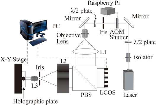
FIGURE 1. Schematic of the fringe printing system. L1 is a collimator lens. Lenses L2 and L3 work as the telecentric imaging system to demagnify the image of LCOS. PBS is a polarizing beam splitter.
Important parameters of output CGH are pixel pitch and resolution. A lens pair of L2 and L3 are used for fine pixel pitch. Since the pixel pitch of LCOS is not small enough for practical CGH for 3D display, the reflected beam from LCOS is reduced by a lens pair of L2 and L3. Demagnification ratio M is described as,
where f2 and f3 are focal length of L2 and L3, respectively. In our system, a part of the computed fringe pattern is displayed on the LCOS that gives the intensity modulation to the illuminated light, and a plane hologram can be output by reducing and exposing it with this optical system.
In our previous report, the demagnification ratio was 1/16 and the pixel pitch of output CGH was 0.44 μm (Yamaguchi et al., 2009b). Table 1 shows the specifications of the printer components. In this paper, we changed lenses L2 and L3 whose focal length is 200 and 10 mm, respectively. The new demagnification ratio is 1/20 and the pixel pitch of output CGH is 0.35 μm. An iris, which is located between L2 and L3, filtered the high order diffraction and the diffraction due to the LCOS structure. Many lens pairs show a better demagnification ratio. However, each lens must pass not only the non-diffracted beam but also the diffracted beam, large ±1-st order diffraction image occurs around L3. Therefore, L3 requires a small F-number. In the previous fringe printer, a Fresnel lens was employed to fulfill the small F-number. Figure 2 shows the output patterns by the previous and proposed fringe printer. Since the previous system employs the Fresnel lens, the output pattern by the previous system was not printed sharply by the lens distortion. On the other hand, the output pattern by the proposed system is printed sharply.
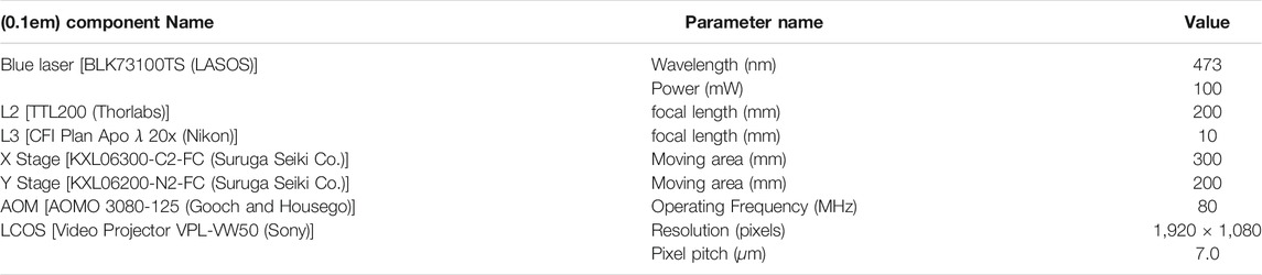
TABLE 1. Components of the fringe printer.
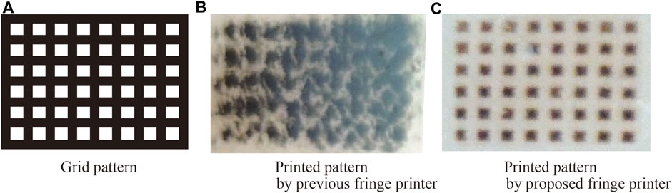
FIGURE 2. Comparison of the printed patterns according to the lens distortion(White areas are printed block as negative image.)
The X-Y stage is used for tiling of fringe pattern which is displayed on LCOS. Since the resolution of LCOS is not suitable for CGH, the fringe printer repeats exposure. The AOM with Raspberry Pi are used as a shutter. The Raspberry Pi sends a signal to control an open/close operation. Since the number of shutter operations necessary to output one CGH exceed 10,000, for example, 300,000 × 150,000 pixels CGH requires 10,981 times shutter operations, the fringe printer does not employ a mechanical shutter. In our previous fringe printer, a mechanical shutter is used. However, since the durable number of the mechanical shutter is around one million, around 100 times the output exceeds the shutter’s durable number. On the other hand, the AOM shutter is an electronic shutter, so it is suitable for a fringe printer.
Computational Operation
Three software packages control the fringe printer. The first software, named BMP Loader, displays part of the fringe pattern on the LCOS panel. The second software, named the Stage Controller, controls the X-Y stage and the AOM shutter. The third software, named the Main Software, manages and connects each software. Figure 3 shows a simple block diagram of the proposed fringe printing system. These software perform serial communication, and each software runs independently.
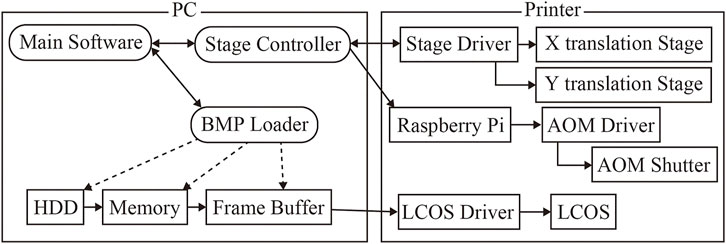
FIGURE 3. Block diagram of the fringe printer system.
Tiling exposure sequence requires a computational operation. Figure 4 shows the exposure order of divided fringe pattern on the X-Y stage. Figure 5 shows the exposure and translation timing for the tiling exposure cycle. Since the image capacity of the fringe pattern sometimes exceeds 100 GB, the whole fringe pattern cannot be stored in the main memory. Therefore, the fringe printer stores a single fringe line, for example, a single fringe line of 300,000 × 150,000 pixels CGH is 300,000 × 1,080, which is determined by the vertical resolution of LCOS. Each fringe pattern is displayed on LCOS and is stored in the frame buffer before exposure. There is also a settling time after stage translation to suppress the stage vibration. As an example, when the exposure time was 15 msec and the settling time was 900 msec, the duration of one cycle was 1.49 msec, although it depended on the exposure conditions.
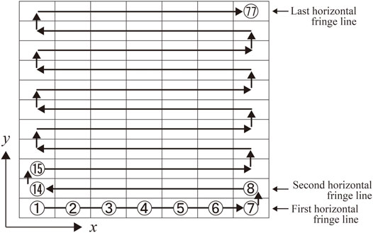
FIGURE 4. Exposure order on the X-Y stage.
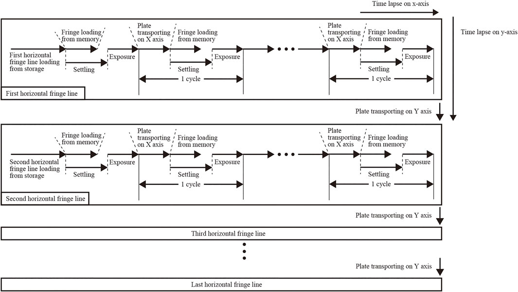
FIGURE 5. Recording process timechart for the fringe printer.
Performance of Fringe Printer
To verify the specification of proposed fringe printer, several experiments were performed. The first parameter is the diffraction angle. The demagnification ratio of the proposed fringe printer has been improved from 1/16 to 1/20. Therefore, diffracted light by the output CGH is measured. The second parameter is the diffraction efficiency. The fringe printer uses the recording material that is VRP–M manufactured by Slavich. The VRP-M is silver halide photomaterial and green–blue sensitive. In the usual holographic recording, the proper exposure energy of VRP-M is 75–100 μJ/cm2. However, single exposure of the fringe printer is a small area, and exposure time is very short compared with usual holographic recordings. Therefore, the diffraction grating is used for the measurement of the diffraction efficiency. Enough settling time is also revealed by the experimental result. In each measurement, the output pattern of the fringe printer is bleached and turns into the phase hologram from the amplitude hologram.
Diffraction Angle
To measure the diffraction angle, the diffraction gratings of the different cycles are prepared. These diffraction gratings have 9,600 × 6,480 pixels and are output by the fringe printer. Figure 6 shows the experimental result of the diffraction angle against the cycle of the diffraction grating. A schematic of the measurement system is shown in Figure 7. The theoretical value in Figure 6 is defined as follows,
The graph shows the experimental result is almost the same as the theoretical value. Therefore, the proposed system can output finer pixel pitch CGH than the previous system. The larger diffraction angle makes it possible to reproduce a larger image in general Fresnel holograms when the incident angle of the reference beam is the same. On the other hand, image-type holograms can provide a wider viewing area when the incident angle of the reference beam is the same.
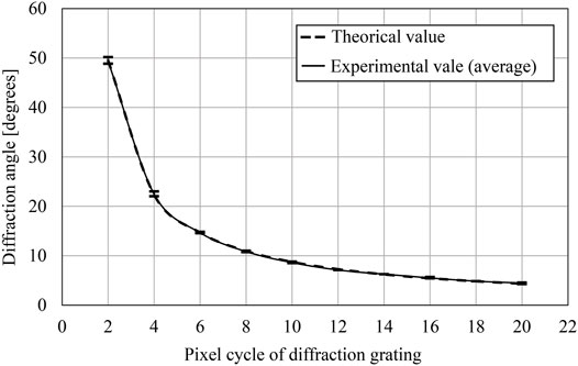
FIGURE 6. A variation of the diffraction angle according to the pixel pitch of the diffraction grating.
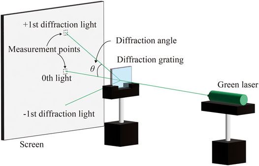
FIGURE 7. Schematic of the measurement system.
Diffraction Efficiency
To obtain the optimum exposure parameter of the fringe printer, the exposure energy and the settling time are measured. Figure 8 shows the variation of the relative diffraction efficiency (International Organization for Standardization, 2015) according to the single exposure energy of the fringe printer. The diffraction grating had enough settling time when it was output. Figure 9 shows the variation of diffraction efficiency according to the settling time. The X-Y stage is used to change the exposure position during the output. If there is any vibration left after the movement, the fringe pattern cannot be recorded correctly, so sufficient settling time is required. Both measurements used Figure 7, and the diffraction efficiency is obtained from the ratio of the transmitted laser power and the +first order diffraction light power. Figure 8 shows the proper exposure energy is about 750 μJ/cm2. Figure 9 shows the stable settling time is over 700 ms.
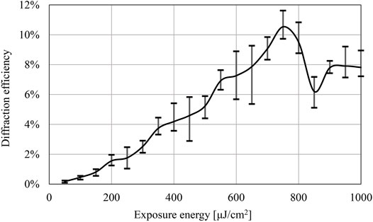
FIGURE 8. A variation of the diffraction efficiency according to exposure energy (Settling time: 1,500 msec)
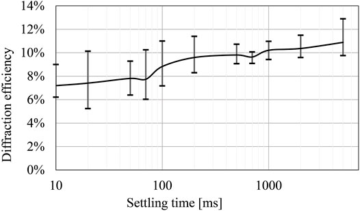
FIGURE 9. A variation of the diffraction efficiency according to the settling time (Sutter time: 1.3 msec)
Reconstructed Image
Figure 10 shows the reconstructed image of the computer-generated rainbow hologram (CGRH) by the proposed fringe printer. The computational method of CGRH is described in detail in Ref. (Yamaguchi and Yoshikawa, 2018).
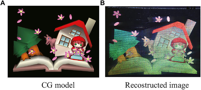
FIGURE 10. Reconstructed image of computer-generated rainbow hologram.288,080 × 194,560 pixels. A: Perspective image of the object. B: Photo of the optically reconstructed image.
Conclusion
This paper has proposed an improved fringe printer with new lens pair to reduce pixel pitch. The new fringe printer can output CGH with a pixel pitch of 0.35 μm. We measured the diffraction angle of the output diffraction grating and confirmed the accuracy of the optical system. We also measured the suitable condition of the exposure. The new fringe printer can provide a large 3D image or a wide viewing area compared with the previous fringe printer. The authors have output various other holograms, such as a computer-generated disk hologram (Yamaguchi et al., 2009a), a holographic stereogram, a computer-generated image hologram (Yamaguchi and Yoshikawa, 2011), and a computer-generated alcove hologram (Yamaguchia et al., 2011), and plan to output them with the new fringe printer in the future.
Data Availability Statement
The original contributions presented in the study are included in the article/Supplementary Material, further inquiries can be directed to the corresponding author.
Author Contributions
Conceptualization, TY and HY; methodology, TY and HY; software, TY; validation, TY and HY; formal analysis, TY and HY; investigation, TY; resources, TY and HY; data curation, TY; writing—original draft preparation, TY; writing—review and editing, TY and HY; visualization, TY; supervision, TY; All authors contributed to manuscript revision, read, and approved the submitted version.
Conflict of Interest
The authors declare that the research was conducted in the absence of any commercial or financial relationships that could be construed as a potential conflict of interest.
Publisher’s Note
All claims expressed in this article are solely those of the authors and do not necessarily represent those of their affiliated organizations, or those of the publisher, the editors and the reviewers. Any product that may be evaluated in this article, or claim that may be made by its manufacturer, is not guaranteed or endorsed by the publisher.
Acknowledgments
The authors would like to thank T. Iwamoto and M. Miyazawa for technical assistance with the experiments. The authors also thank Team–Opt Corp. for technical advice with the optical design.
References
Hamano, T., and Yoshikawa, H. (1998). Image-type CGH by Means of E-Beam Printing. Proc. SPIE 3293, 2–14.doi:10.1117/12.303638
International Organization for Standardization (2015). Optics and Photonics – Holography – Part 1: Methods of Measuring Diffraction Efficiency and Associated Optical Characteristics of Holograms. Geneva. ISO 17901-1:2015.
Nakaguchi, Y., Yamaguchi, T., and Yoshikawa, H. (2010). Computer-generated Rainbow Hologram over 100 Giga-Pixel. Int. Conf. 3D Syst. Appl., 107–110.
Nishi, H., and Matsushima, K. (2017). Rendering of Specular Curved Objects in Polygon-Based Computer Holography. Appl. Opt. 56, F37–F44. doi:10.1364/ao.56.000f37
Sakamoto, Y., Morishima, M., and Usui, A. (2004). Computer-generated Holograms on a CD-R Disk. SPIE Proc. Pract. Holography XVIII 5290, 28–34. doi:10.1117/12.526504
Yamaguchi, T., Fujii, T., and Yoshikawa, H. (2009a). Disk Hologram Made from a Computer-Generated Hologram. Appl. Opt. 48, H16–H22. doi:10.1364/ao.48.000h16
Yamaguchi, T., Matuoka, M., Fujii, T., and Yoshikawa, H. (2009b). “Development of Fringe Printer and its Practical Applications,” in Proceedings of the 8th International Symposium on Display Holography.
Yamaguchi, T., Fujii, T., and Yoshikawa, H. (2008). Fast Calculation Method for Computer-Generated Cylindrical Holograms. Appl. Opt. 47, D63–D70. doi:10.1364/ao.47.000d63
Yamaguchi, T., Miyamoto, O., and Yoshikawa, H. (2012). Volume Hologram Printer to Record the Wavefront of Three-Dimensional Objects. Opt. Eng. 51 (1–7), 075802.doi:10.1117/1.OE.51.7.075802
Yamaguchi, T., and Yoshikawa, H. (2011). Computer-generated Image Hologram. Chin. Opt. Lett. 9 (1–4), 120006. doi:10.3788/COL201109.120006
Yamaguchi, T., and Yoshikawa, H. (2018). High Resolution Computer-Generated Rainbow Hologram. Appl. Sci. 8, 1955. doi:10.3390/app8101955
Yamaguchia, T., Ozawa, H., and Yoshikawaa, H. (2011). Computer-generated Alcove Hologram to Display Foating Image with Wide Viewing Angle. Proc. SPIE 7959 (1–10), 795719.
Yoshikawa, H., and Takei, K. (2004). Development of a compact direct fringe printer for computer-generated holograms,. Proc. SPIE 5290, 114–121.doi:10.1117/12.526516
Yoshikawa, H., and Taniguchi, H. (1999). Computer Generated Rainbow Hologram. Opt. Rev. 6, 118–123. doi:10.1007/s10043-999-0118-0
Keywords: Holography, computer-generated hologram, fringe pattern, high resolution, pixel pitch
Citation: Yamaguchi T and Yoshikawa H (2022) Development of a Fringe Printer With 0.35 μm Pixel Pitch. Front. Photonics 3:843860. doi: 10.3389/fphot.2022.843860
Received: 27 December 2021; Accepted: 02 March 2022;
Published: 28 March 2022.
Edited by:
Peter Wai Ming Tsang, City University of Hong Kong, Hong Kong SAR, ChinaReviewed by:
Tomasz Kozacki, Warsaw University of Technology, PolandHongbo Zhang, Virginia Military Institute, United States
Copyright © 2022 Yamaguchi and Yoshikawa. This is an open-access article distributed under the terms of the Creative Commons Attribution License (CC BY). The use, distribution or reproduction in other forums is permitted, provided the original author(s) and the copyright owner(s) are credited and that the original publication in this journal is cited, in accordance with accepted academic practice. No use, distribution or reproduction is permitted which does not comply with these terms.
*Correspondence: Takeshi Yamaguchi, eWFtYWd1Y2hpLnRha2VzaGk4OUBuaWhvbi11LmFjLmpw