 Joan Palacios
 Nuria González-Prelcic
 Carlos Mosquera
 Takayuki Shimizu
 Chang-Heng Wang
- 1Electrical and Computing Engineering Department, North Carolina State University, Raleigh, NC, United States
- 2atlanTTic Research Center, Universidade de Vigo, Vigo, Spain
- 3Toyota Motor North America, Mountain View, CA, United States
5G and future cellular networks intend to incorporate low earth orbit (LEO) satellite communication systems (SatCom) to solve the coverage and availability problems that cannot be addressed by satellite-based or ground-based infrastructure alone. This integration of terrestrial and non terrestrial networks poses many technical challenges which need to be identified and addressed. To this aim, we design and simulate the downlink of a LEO SatCom compatible with 5G NR, with a special focus on the design of the beamforming codebook at the satellite side. The performance of this approach is evaluated for the link between a LEO satellite and a mobile terminal in the Ku band, assuming a realistic channel model and commercial antenna array designs, both at the satellite and the terminal. Simulation results provide insights on open research challenges related to analog codebook design and hybrid beamforming strategies, requirements of the antenna terminals to provide a given SNR, or required beam reconfiguration capabilities among others.
1 Introduction
Integrated satellite-terrestrial cellular networks are currently being pursued for long awaited commercial applications. The main expected benefit is an uninterrupted coverage, even in unserved/underserved areas. LEO constellations seem to be the most promising platforms for satellite-based non-terrestrial networks (NTNs), due to their relatively shorter propagation delay (Kodheli et al., 2017). Although this propagation delay between ground terminals and LEO satellites (3 ms at 1,000 km above the Earth surface) is non-negligible, LEO constellations can support continuity and ubiquity of the radio services, and also latency critical applications with requirements within tens of ms.
Beam configuration and reconfiguration in a link between a LEO satellite and a ground mobile terminal is challenging due to the long round trip delay, fast movement of the satellite and limited on board processing capabilities. Current LEO constellations (del Portillo et al., 2019) make use of fixed analog beams that illuminate a given area of the Earth’s surface, without any capability to steer narrow beams in the user directions. Digital precoding stages are designed independently of the analog beam with the purpose of reducing inter-beam interference among the beams illuminating adjacent regions of interest (ROI) (Devillers and Pérez-Neira, 2011). Moreover, these solutions assume that a single satellite is illuminating a large specific ROI, and handover procedures are put in place to enable satellite switching at the user side before the satellite movement causes loss of coverage.
Designing the LEO satellite footprint and the specific beam codebook at the satellite side in an integrated satellite-terrestrial network is challenging. The potential beampatterns need to be designed to guarantee coverage of the Earth’s surface, limit the inter-beam interference, maximize system throughput, and, at the same time, exhibit some degree of compatibility with conventional codebooks defined in cellular standards. Commercial efforts on deploying LEO constellations, not necessarily for integration with the terrestrial network, are described in (del Portillo et al., 2019; Xia et al., 2019). Sizes of the beam footprints for the different deployments are provided, but the details of the beam codebook are not available. The massive MIMO LEO satellite communication system designed in (You et al., 2020) considers the set of all feasible beams generated by a uniform planar array at the satellite rather than a codebook, without trying to reduce the inter-beam interference or the amount of on-board processing.
In this paper, we propose and evaluate a massive MIMO LEO satellite communication system operating in the Ku band, based on a hybrid beamforming architecture. In particular, we design first the footprint associated to a given LEO satellite. Then, we design the beam codebook for the hybrid beamforming stage such that the derived footprint is covered by the beams in the codebook. We build our design using a 2-D DFT-based grid of beams as in Type I and Type II 5G New Radio CSI codebooks (Miao et al., 2018; Ericsson, 2017a; Ericsson, 2017b; Samsung, 2017; Technical Specification Group Radio Access Network, 2017a; b), considering an oversampling factor to shape the available beampatterns to the size of the satellite footprint. Assuming this codebook at the satellite and commercially available SatCom antennas for the mobile terminals, we evaluate the coverage and throughput of this LEO massive MIMO system operating in the Ku band. Additional performance metrics such as SNR degradation over time or inter-beam interference are also evaluated. Numerical results provide the baseline performance of a state-of-the art massive MIMO LEO satellite communication system and allow the identification of open research challenges.
2 System Model
We consider the downlink of a massive MIMO LEO satellite communication system operating in the Ku band, as in current commercial deployments (del Portillo et al., 2019), and also compliant with the 3GPP proposal for 5G broadband satellite services (Angeletti and De Gaudenzi, 2020). We denote as
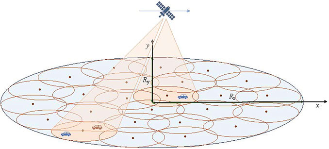
FIGURE 1. System model for a LEO satellite communication system covering an elliptical area using a predefined beam codebook.
2.1 MIMO Architecture and Antenna Models
We assume that the satellite is equipped with a large uniform planar array (UPA) with dimension
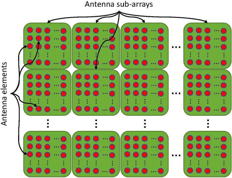
FIGURE 2. Partially connected sub-array structure at the satellite antenna. Each subarray is controlled by a single RF-chain.
Assuming a hybrid architecture, the precoding matrix consisting on
For the antenna arrays at the mobile terminal, we consider three possible solutions that enable beamforming in the satellite direction. The first one is a uniform planar array (UPA) of moderate size, with dimensions
We define
For a leaky wave antenna with leakage factor α, a feasible beam-patterns
Finally, the metasurface antenna designed by Kymeta has a peak gain of 33 dB and a 1.2 cosine roll-off factor. This translates into a gain of
2.2 Channel Model
We consider the channel between a single LEO satellite located at position
where
2.2.1 Link Budget Model
The link power loss includes the free space path loss, denoted as
where
The free space path loss in dB is given by
with
Defining
The integral is performed over the efficient limits of the atmosphere, that is between the user’s height
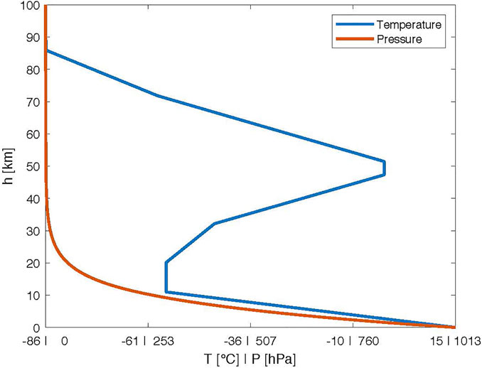
FIGURE 3. 1976 Standard Atmospheric model showing temperature and pressure vertical profiles.
2.2.2 Satellite Angular Speed and Doppler Effects
The satellite movement at a speed
Note that the angular speed is computed in absolute terms and it is not directly related to a parametrization of choice, like for example polar coordinates from the UT point of view. Therefore, it does not translate to variational speed of azimuth and elevation angles. We discourage the use of satellite tracking strategies using a polar parametrization to avoid sharp changes in the azimuth direction. For example, considering a unitary sphere centered in the origin in an arbitrary Cartesian coordinate system and its corresponding polar parametrization, a small change of direction from
The Doppler effect caused by the satellite’s movement is increasing and anti-symmetric in the movement’s direction, thus its maximum is located at the elliptical footprint boundary. By creating orbits with many satellites, we can reduce the maximum absolute Doppler effect, since the distance between satellites decreases, thus reducing the size of the covered area in the direction of movement. As for the relative angular speed, the effect is symmetric concave with a maximum in the satellite’s shadow. Therefore, the maximum is not affected by the satellite’s density. Using basic geometry, these maximum values are given by the following formulas
The maximum Doppler caused by the satellite’s movement can be simplified when
The Doppler effect caused by the UT moving with the speed vector
2.2.3 Channel Matrix
Due to the large distance and lack of medium interaction, a Rician geometric channel model with power β and Rician factor
where
3 System Design
3.1 Design of the Coverage Area
We consider a LEO constellation where satellites are distributed around
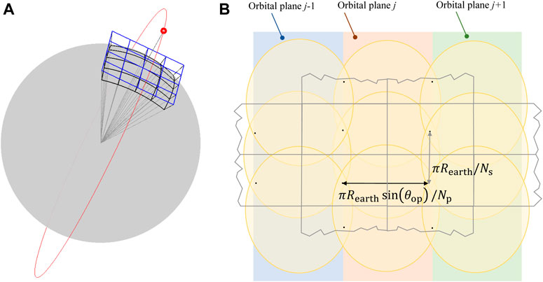
FIGURE 4. Design of the satellite elliptical footprint. (A) Stereographic parametrization of the area covered by the satellite. (B) Illustration of the design process.
To design the sizes of the semiradiuses of the elliptical ROI, we will force the LEO constellation to cover the entire Earth. Thus, the equivalent flat problem we want to solve is to cover the entire Earth surface with ellipses centered in the vertices of a rectangular grid with spacing
An example of a semiradius pair that fulfills this condition is
3.2 Beam Codebook Design
Our goal is to design a set of analog beampatterns or beam codebook, such that the set of beam footprints covers an ellipsoidal ROI as that described in the previous section. Depending on the location of the active users, some active beams will be selected from the set available in the codebook. We will consider a DFT-based analog precoder codebook structure, a popular solution when operating with planar arrays. In this case, the array response vectors in each dimension have a linearly increasing phase, like the columns in the DFT matrix. Therefore, the MIMO channel can be written in terms of array response vectors with this structure. DFT-based precoders match in this case the channel structure providing a good beamforming gain. Note that the column vectors in a DFT codebook generate a grid of beams (GoB) that can be used to span all angular directions, as illustrated in Figure 5 for a planar array with 16 panels (subarrays), and
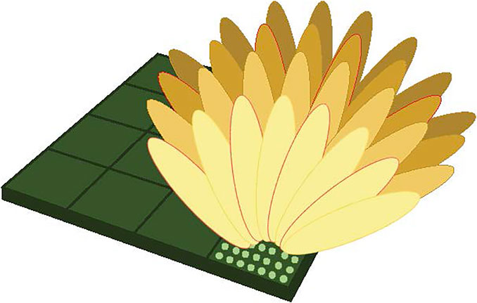
FIGURE 5. Illustration of the GoB generated with a 2D DFT codebook with an oversampling factor of 2. Orthogonal beams are marked in red.
In particular, 5G New Radio defines what is called a Type II DFT codebook, where an oversampling factor is introduced in the definition of array steering vectors for azimuth and elevation (Miao et al., 2018; Ericsson, 2017a, b; Samsung, 2017; Technical Specification Group Radio Access Network, 2017a, b). The goal of the oversampling factor, which is fixed and equal to 4 in 5G NR, is to mitigate the loss of beamforming gain in directions between orthogonal beams (straddling loss). This way, beam orthogonality is lost in general, and only beams spaced the oversampling factor are orthogonal. Figure 5 shows the set of orthogonal beams marked in red when an oversampling factor equal to 2 has been used in each dimension.
In our design, we will also consider a 2D oversampled DFT codebook for each subarray, although the oversampling factor O is not fixed, allowing the adjustment of the number of beams that illuminate footprints of different sizes for some given RF resources. The elements of the block diagonal RF precoding matrix
for
Once the codebook is created, the cells are defined as the areas inside the elliptical ROI where a given beam provides a higher gain than any other beam in the available codebooks for all the subarrays. Note that the DFT nature of the designed codebook creates a rectangular tiling of the ROI. Section 5 includes examples of the beam footprints when this type of codebook is assumed on board.
4 Coverage and Spectral Efficiency Calculation
4.1 Coverage
When operating with a transmitting beam-pattern
Note that this expression depends on the user and satellite positions in
To compute the combining gain at the UT side, we will consider the LoS direction to be known (in the system model we have assumed that the satellite position is known) and the Rician component of the channel to be unknown. Thus, the combiner
Now, if we make use of the definition of
Since the LEO satellite is transmitting simultaneously through multiple beams with a gain
with
4.2 Throughput and Spectral Efficiency
We consider the throughput expression given by the capacity
5 Simulation Results
Unless otherwise specified, we consider a LEO satellite orbiting at a 1,300 km height, covering an ellipsoidal ROI with semiradius 534.1 and 170.5 km. This area has been designed following the procedure described in 3.1 for a LEO constellation with 83 orbits with an inclination of
To understand the role of the oversampling factor O in the beam codebook presented in Section 3.2, we show in Figure 6 different mesh designs covering the elliptical ROI for a
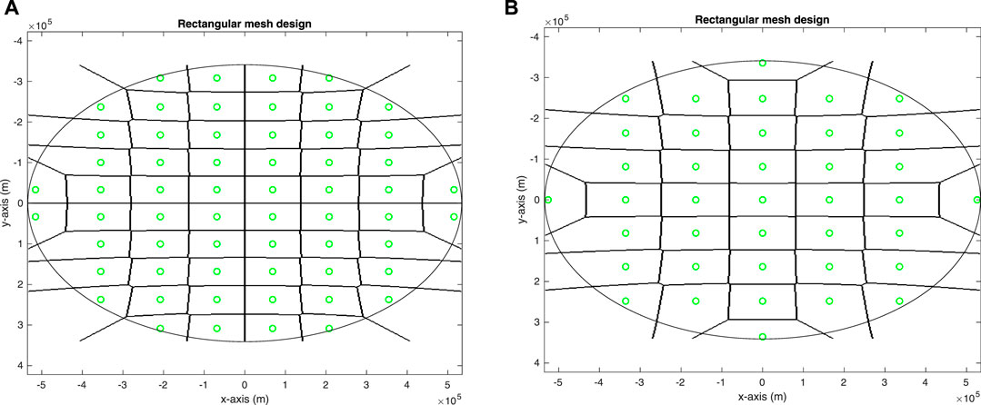
FIGURE 6. Examples of rectangular mesh covering an elliptical ROI when using the oversampled DFT beam codebook: (A) with
For the next simulations we will assume that the satellite phased arrays consist of
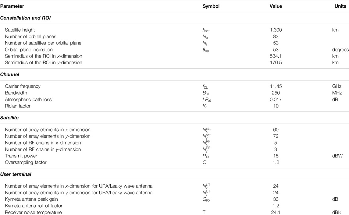
TABLE 1. System parameters for the simulation of the downlink of a LEO SatCom system operating in the Ku band.
To understand the impact of different antennas at the user terminal, we will consider both the UPA and the leaky wave antenna (denoted as CRLH-LW) to have a number of elements equal to
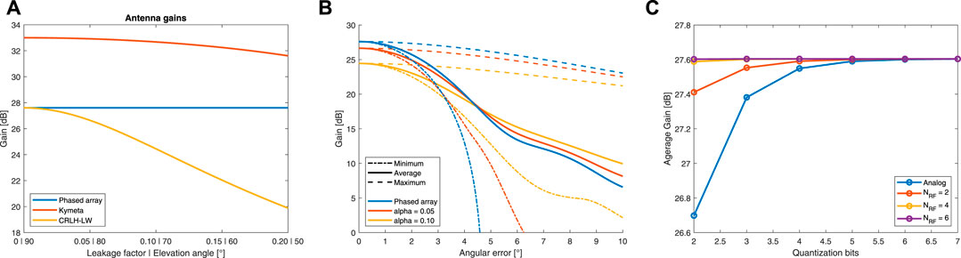
FIGURE 7. Gain provided by the different antenna terminals: (A) Gain with perfect beam alignment. (B) Gain under misalignment. (C) Gain under phase quantization.
We consider now the effect of beam misalignment on the gain through Monte Carlo simulation for the phased antenna array and the leaky wave antenna. Figure 7B shows that, on average, the gains stay within reasonable levels, but the minimum values become critical under an error greater than
Next, we analyze the coverage of the elliptical ROI provided by the beam codebook at the satellite when the UPA is considered as antenna terminal. As shown in Section 4.1,
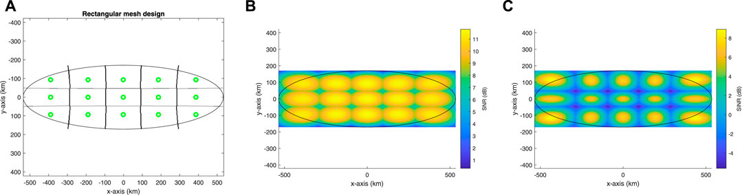
FIGURE 8. (A) Cells associated to the different beampatterns; point marked in green show the location where the beampattern gain is maximum. (B) SNR when using the best beam for each cell. (C) SINR when using the best beam for each cell.
This SNR and SINR translate into the spectral efficiency shown in Figure 9. Note that there is a significant inter-beam interference when operating with DFT-type codebooks as proposed in LTE and 5G NR. Future work needs to be developed to design alternative analog codebooks and hybrid beamforming strategies at the satellite side to reduce inter-beam interference.
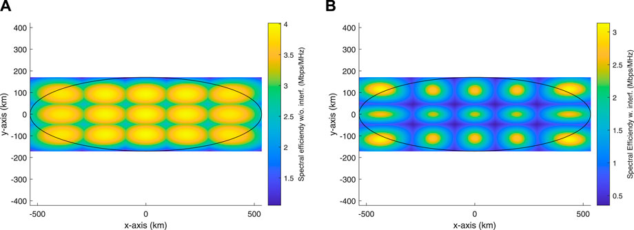
FIGURE 9. (A) Spectral efficiency when ignoring interference. (B) Spectral efficiency when considering interference.
To further extend the coverage analysis, in Figure 10 we see how the SNR, SINR and their corresponding spectral efficiencies are distributed over the ROI as CDF curves. It is easy to appreciate the huge impact of inter-beam interference, hinting how important the design of good interference mitigation techniques is for satellite communications.
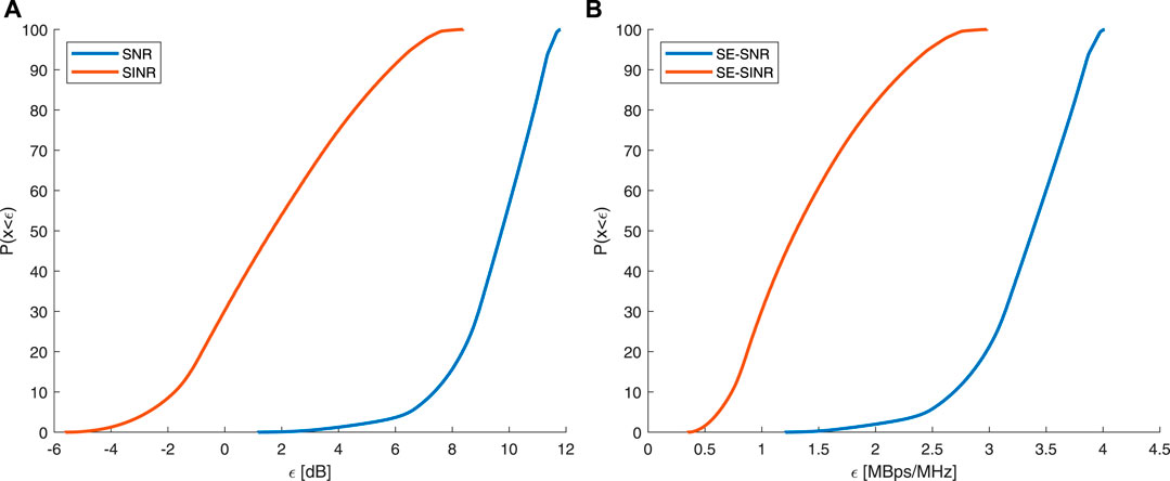
FIGURE 10. Cumulative distribution function inside the ROI of: (A) SNR and SINR. (B) Spectral efficiency computed for the SNR and SINR.
Figure 11 shows the satellite’s angular speed relative to the user and the Doppler effect due to the satellite’s movement as a function of the user’s relative location. The relative angular speed shows significantly small values. This means that the beampattern switching requirements of a given antenna design that enable tracking of the satellite’s position for beamforming are not particularly challenging. Note that this holds when tracking the satellite direction, not its corresponding azimuth and elevation angles. If the angular relative speed is translated into a maximum azimuth and elevation angular variation with time, the azimuth angle can present sharp changes, as illustrated in Section. 2.2.2.
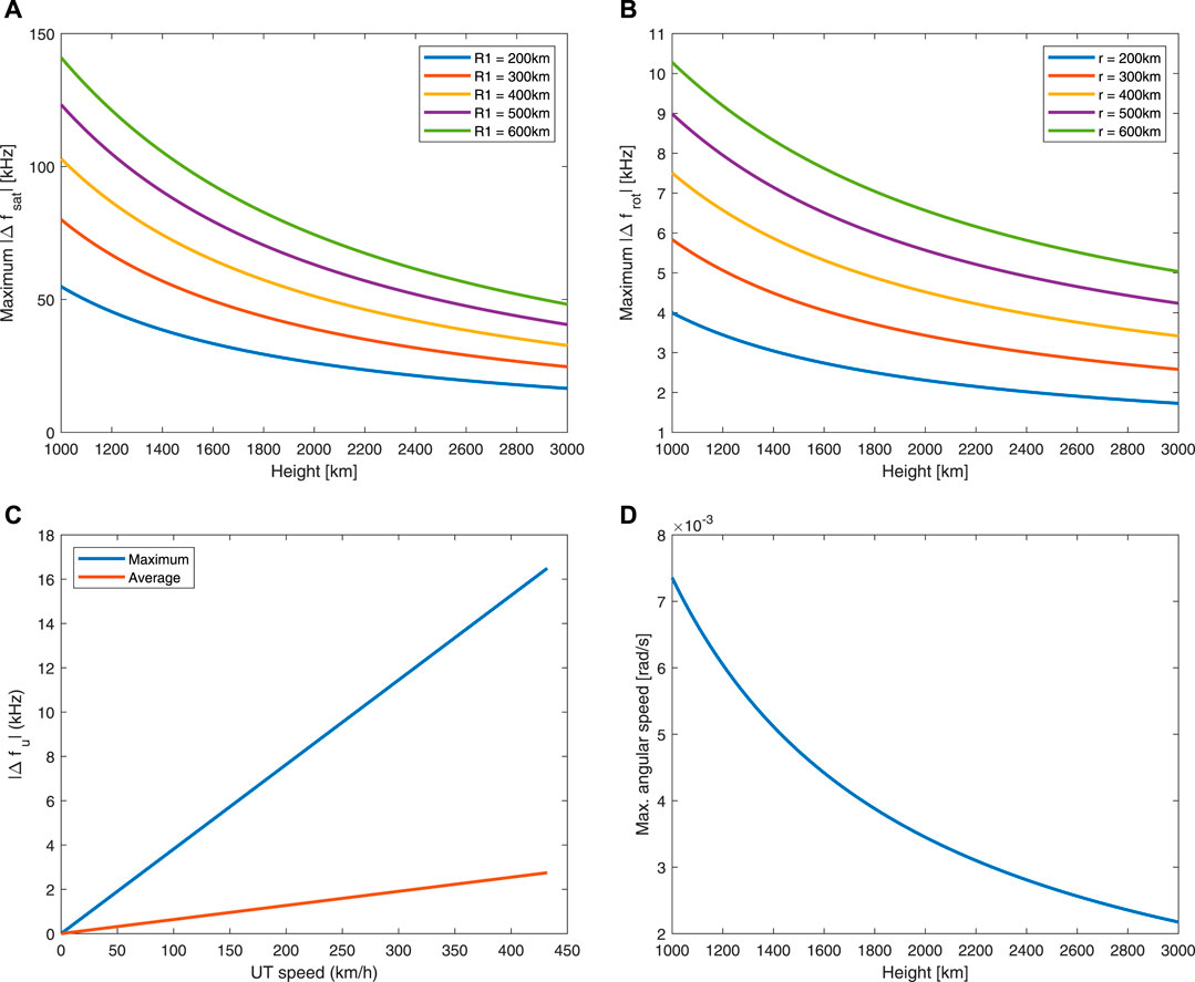
FIGURE 11. (A–C) Doppler effect for the central frequency caused by the satellite’s movement, Earth rotation and UT movement respectively. (D) Satellite’s angular relative speed with respect to the user terminal.
Finally, we analyze the SNR degradation over time due to the satellite’s movement for a user initially located at the center of the elliptical ROI. We have considered a beam selection strategy based on maximizing SNR. Figure 12A shows an example of different satellite positions and associated selected beams. Figure 12B shows the SNR corresponding to the different satellite positions illustrated in (a). It can be concluded that, for this codebook design and system parameters, the user is illuminated by the same beam for a period of around 30 s. After that, another beam has to be selected to keep a proper gain. Note that even after updating the best beam, there is a non-negligible gain loss due to the satellite movement, as also illustrated in Figure 12B.
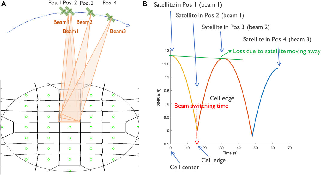
FIGURE 12. (A) Example of different satellite positions and associated beams. (B) SNR degradation over time due to the satellite’s movement.
6 Conclusion
Research on integrating LEO-based satellite networks with terrestrial networks is still in its infancy. We implemented a complete simulator of the downlink of a massive MIMO LEO SatCom system to understand the physical layer challenges and evaluate a hybrid beamforming strategy based on an analog codebook. We designed the satellite footprint as an elliptical ROI given the number of orbital planes and number of satellites per orbit. We also designed a static DFT-type codebook, as commonly used in current cellular standards, to adjust the beamwidth and RF resources to the size of the satellite footprint by means of an interpolation factor. Simulation results show the relevance of the antenna terminal design to achieve an acceptable SNR. Our numerical experiments also show that DFT codebooks introduce a high inter-beam interference which reduces the ability of the system to provide a high spectral efficiency at all locations inside the ROI. Designing fully or partially connected hybrid beamforming architectures with per antenna power constraints and a digital precoder that mitigates inter-beam interference is an open research challenge that needs to be addressed to overcome the SINR performance of current approaches. The design of low complexity dynamic codebooks that better adapt the resources to the specific location of the users and reduce the SNR loss due to the satellite movement is a critical challenge. Our simulator also shows that the variation of the relative angular speed between the satellite and the UT is smooth when working with spherical coordinates. This leads to the need of designing beam tracking methods for the UT that track the satellite position rather than its variation in elevation and azimuth. Our numerical experiments also show the effectiveness of exploiting satellite position information at the UT side to avoid the need of channel estimation and tracking, which will provide old estimates due to the long transmission delay. Finally, an accurate model for the error in the satellite’s position and trajectory is also necessary to better understand its impact in the performance of the satellite beam tracking strategies.
Data Availability Statement
The original contributions presented in the study are included in the article/supplementary material, further inquiries can be directed to the corresponding author.
Author Contributions
JP and NG-P contributed to the design and development of the investigation, including mathematical derivations and code for the simulations. NG-P and CM provided technical direction. JP and NG-P wrote the draft of the manuscript. CM, TS and C-HW participated in technical discussions of the results and provided comments of the manuscript.
Funding
This work has been partially funded by Toyota Motor North America.
Conflict of Interest
Authors TS and C-HW were employed by the company Toyota Motor North America.
The remaining authors declare that the research was conducted in the absence of any commercial or financial relationships that could be construed as a potential conflict of interest.
Publisher’s Note
All claims expressed in this article are solely those of the authors and do not necessarily represent those of their affiliated organizations, or those of the publisher, the editors and the reviewers. Any product that may be evaluated in this article, or claim that may be made by its manufacturer, is not guaranteed or endorsed by the publisher.
References
Angeletti, P., and De Gaudenzi, R. (2020). A Pragmatic Approach to Massive MIMO for Broadband Communication Satellites. IEEE Access 8, 132212–132236. doi:10.1109/access.2020.3009850
De Gaudenzi, R., Angeletti, P., Petrolati, D., and Re, E. (2020). Future Technologies for Very High Throughput Satellite Systems. Int. J. Satell Commun. Netw. 38, 141–161. doi:10.1002/sat.1327
del Portillo, I., Cameron, B. G., and Crawley, E. F. (2019). A Technical Comparison of Three Low Earth Orbit Satellite Constellation Systems to Provide Global Broadband. Acta Astronautica 159, 123–135. doi:10.1016/j.actaastro.2019.03.040
Devillers, B., and Pérez-Neira, A. (2011). “Advanced Interference Mitigation Techniques for the Forward Link of Multi-Beam Broadband Satellite Systems,” in 2011 Conference Record of the Forty Fifth Asilomar Conference on Signals, Systems and Computers (ASILOMAR), 1810–1814. doi:10.1109/ACSSC.2011.6190334
Ericsson, (2017b). Type II CSI for Beamformed CSI-RS and Hybrid Operation. Tech. Rep. R1-1708699. Hangzhou, China. Meeting RAN1#89, 3GPP.
Kim, J., Yun, M. Y., You, D., and Lee, M. (2020). “Beam Management for 5G Satellite Systems Based on NR,” in 2020 International Conference on Information Networking (ICOIN), 32–34. doi:10.1109/icoin48656.2020.9016571
Kodheli, O., Guidotti, A., and Vanelli-Coralli, A. (2017). “Integration of Satellites in 5G through LEO Constellations,” in GLOBECOM 2017 - 2017 IEEE Global Communications Conference, 1–6. doi:10.1109/glocom.2017.8255103
[Dataset] Kymeta (2019). Link Budget Calculations for A Satellite Link with an Electronically Steerable Antenna Terminal.
Mehdipour, A., and Eleftheriades, G. V. (2014). Leaky-Wave Antennas Using Negative-Refractive-Index Transmission-Line Metamaterial Supercells. IEEE Trans. Antennas Propagat. 62, 3929–3942. doi:10.1109/TAP.2014.2322882
Mehdipour, A., Sazegar, M., and Stevenson, R. (2019). “Broadband WAIM Metasurface Structure for Electronically Beam Scanning Holographic Antenna for Ku-Band Satellite Communications,” in 2019 IEEE International Symposium on Antennas and Propagation and USNC-URSI Radio Science Meeting, 429–430. doi:10.1109/APUSNCURSINRSM.2019.8888376
Miao, H., Mueck, M. D., and Faerber, M. (2018). “Amplitude Quantization for Type-2 Codebook Based CSI Feedback in New Radio System,” in 2018 European Conference on Networks and Communications (EuCNC). 1–9. doi:10.1109/EuCNC.2018.8442609
Palacios, J., De Donno, D., Giustiniano, D., and Widmer, J. (2016). “Speeding up mmWave Beam Training through Low-Complexity Hybrid Transceivers,” in 2016 IEEE 27th Annual International Symposium on Personal, Indoor, and Mobile Radio Communications (PIMRC), 1–7. doi:10.1109/PIMRC.2016.7794709
Samsung (2017). WF on Type I and II CSI Codebooks. Tech. Rep. R1-1709232. Hangzhou, China. Meeting RAN1#89, 3GPP.
Sikri, D., and Jayasuriya, R. M. (2019). Multi-Beam Phased Array with Full Digital Beamforming for SATCOM and 5G. Microwave J. 60 (4), 64–79.
[Dataset] Technical Specification Group Radio Access Network (2017a). TR38.211. NR; Physical Channels and Modulation (Release 15).
[Dataset] Technical Specification Group Radio Access Network (2017b). TR38.214. NRPhysical Layer Procedure for Data (Release 15).
[Dataset] Technical Specification Group Radio Access Network (2019). TR38.821. Solutions for NR to Support Non-terrestrial Networks (NTN) (Release 16).
Xia, S., Jiang, Q., Zou, C., and Li, G. (2019). Beam Coverage Comparison of LEO Satellite Systems Based on User Diversification. IEEE Access 7, 181656–181667. doi:10.1109/access.2019.2959824
Keywords: beam codebook, massive MIMO, LEO satellite communications, non-terrestrial networks, hybrid beamforming
Citation: Palacios J, González-Prelcic N, Mosquera C, Shimizu T and Wang C-H (2021) A Hybrid Beamforming Design for Massive MIMO LEO Satellite Communications. Front. Space Technol. 2:696464. doi: 10.3389/frspt.2021.696464
Received: 16 April 2021; Accepted: 08 July 2021;
Published: 27 September 2021.
Edited by:
Tomaso De Cola, Helmholtz Association of German Research Centers (HZ), GermanyReviewed by:
Jue Wang, Nantong University, ChinaNicolò Mazzali, European Space Research and Technology Centre (ESTEC), Netherlands
Copyright © 2021 Palacios, González-Prelcic, Mosquera, Shimizu and Wang. This is an open-access article distributed under the terms of the Creative Commons Attribution License (CC BY). The use, distribution or reproduction in other forums is permitted, provided the original author(s) and the copyright owner(s) are credited and that the original publication in this journal is cited, in accordance with accepted academic practice. No use, distribution or reproduction is permitted which does not comply with these terms.
*Correspondence: Nuria González-Prelcic, bmdwcmVsY2ljQG5jc3UuZWR1